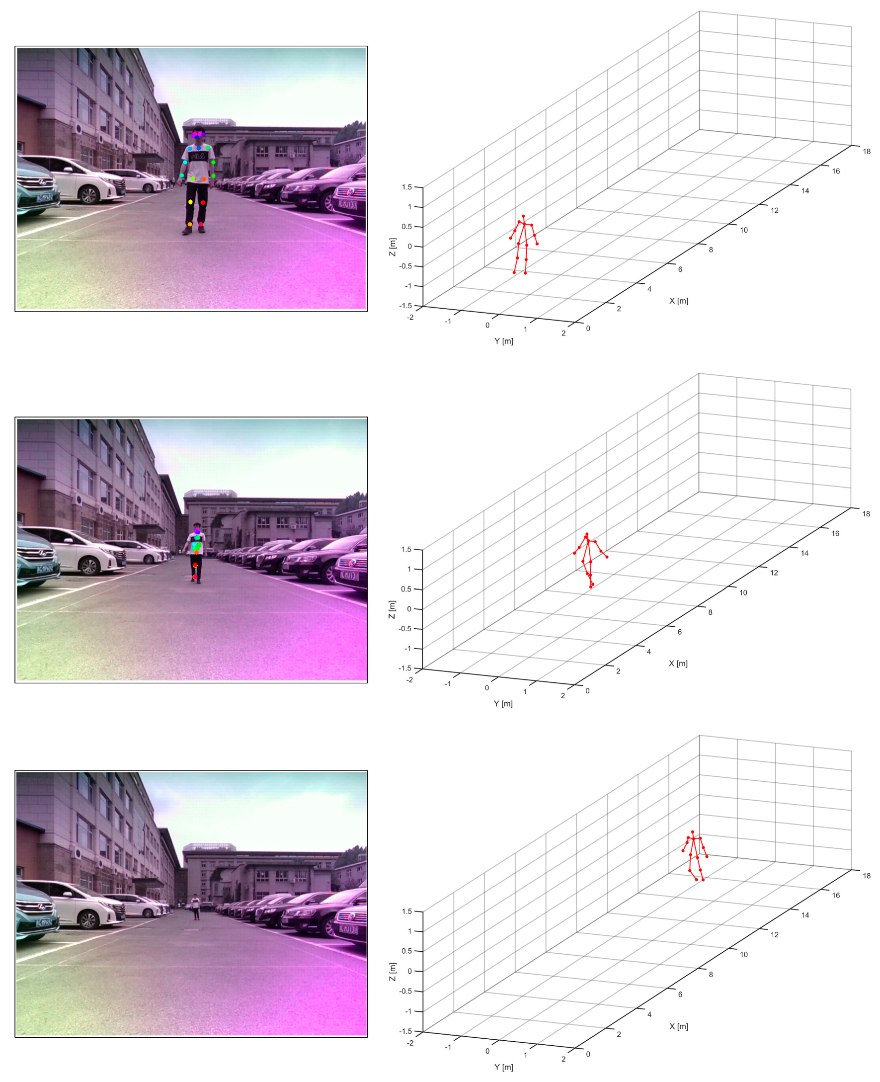
1. Introduction
Skeletal pose estimation, especially for pedestrians and cyclists, is important for autonomous driving, road monitoring, and other applications. Estimating the current posture of vulnerable road users, such as walking, running, jumping, waving, cycling, etc., can aid in preventative decision making [
1]. In addition to the transportation domain, skeletal pose estimation has attracted much attention in home behavior monitoring, medical patient monitoring, human–computer interaction, and other applications.
Skeletal pose estimation was first studied in computer vision and artificial intelligence. Recently, a large number of solutions have been proposed for 2D and 3D human pose estimation [
2,
3,
4]. In existing studies on human pose estimation, the sensors used include vision sensors, radar, RFID [
5,
6], tactile sensors [
7], etc. The tactile sensor-based skeletal pose recognition uses the force exerted by the target to obtain data from the tactile sensor. This is a scheme suitable for small indoor applications. RFID-based skeletal pose recognition requires the installation of multiple radio tags on the surface of the test target, and the system is complex and not scalable. Skeletal pose recognition with vision sensors is the prevailing scheme, but existing vision schemes do not work effectively in dark environments, line-of-sight occlusion, and distant targets, which makes it difficult to directly apply vision sensor-based skeletal pose recognition to automatic driving and other road scenarios. Radar is robust to illumination and weather compared to vision sensors, and millimeter-Wave (mmWave) Multiple-Input Multiple-Output (MIMO) radar has a higher resolution than conventional radar, which has been widely used in the autonomous driving of vehicles [
8]. Therefore, the radar sensor can be used as a high-quality complementary solution to the visual sensor for the estimation of the user’s skeletal pose in the real road environment.
The direct recovery of fine skeletal poses from radar images is difficult due to the low resolution of radar imaging. By applying deep learning techniques, the automatic estimation of skeletal poses can be achieved without hand-crafted features. However, training deep learning models is data greedy and requires a large amount of manually labeled data to guarantee performance [
9,
10,
11]. On the scattering mechanism of an electromagnetic wave, optical scattering mainly occurs when visible and infrared wavelengths (350–1000 nm) perceived by visual sensors interact with targets. However, the interaction between the microwave frequency band (1 mm–1 m) perceived by the radar sensor and targets mainly takes place with Rayleigh scattering and Mie scattering. The difference in scattering mechanisms makes radar images more abstract than optical images, so it is not possible to manually label radar image datasets as it is for optical images. RF-Pose [
12] solves the radar data-labeling problem by introducing cross-modal supervised learning techniques for the first time, synchronously collecting visual and radar data, and using optical data as supervision.
By applying cross-modal supervised learning techniques, the radar-based skeletal pose estimation schemes can be divided into two categories based on the radar system, namely, the planar array radar-based skeletal pose estimation scheme and the linear array radar-based skeletal pose estimation scheme. The planar array radar-based skeletal pose estimation scheme can obtain a 3D point cloud of the target in range–azimuth–pitch space and estimate the skeletal pose based on it. Under certain requirements of estimation accuracy and robustness, the signal processing complexity of this scheme is low, but the radar system is highly complex. Skeletal pose estimation based on a single linear array radar can only obtain 2D spatial information of the target due to the observation dimension limitation. Under certain estimation accuracy and robustness requirements, this scheme has low radar system complexity but high signal processing complexity. In road applications such as automatic driving, automotive radar sensors have stringent requirements on volume, power consumption and cost. Therefore, it is difficult for the scheme based on planar array radar to meet the application requirements. For the scheme based on a single linear array radar, although it meets the requirements at the system level, the absence of the system observation dimension may lead to errors in some cases, which is unacceptable in terms of road traffic safety.
To balance the performance and complexity of radar systems, a distributed non-coherent radar system is proposed in this paper. It consists of two linear radars placed horizontally and vertically. By combining the range–azimuth and range–pitch dimension of the non-coherent signal, the lack of observation dimension of a single linear radar can be overcome, and the system cost and complexity can be greatly reduced compared to a planar array radar. We study the quantitative relationship between the resolution of a radar system and the accuracy of pose estimation based on a distributed non-coherent radar system. Meanwhile, we propose a deep learning model training method based on multi-resolution radar images to achieve remote object pose estimation that cannot be detected by visual sensors. Moreover, the object of pose estimation is extended from pedestrians to cyclists, which makes the results of pose estimation more consistent with the real world. Finally, skeletal pose estimation for vulnerable road users such as pedestrians and cyclists is implemented in this paper. The proposed method is also applicable to long-distance and multi-target environments.
The main contributions of the paper are briefly summarized as follows.
In terms of radar system, a non-coherent radar system is proposed for the detection of vulnerable road users, and the relationship between the radar resolution and the estimation accuracy of skeletal posture is analyzed.
In terms of modeling, a deep learning network, called RVRU-Pose, which is applicable to non-coherent radar for skeletal posture estimation, is proposed to achieve an accurate estimation of human posture. Furthermore, based on this model, the estimation of the skeletal pose of the cyclist is also implemented.
In terms of model generalization, a multi-resolution data augmentation and training method is proposed for radar to achieve pose estimation for long-range and multi-target application scenarios.
The rest of the paper is structured as follows.
Section 2 gives a brief overview of related works on fine-grained human sensing tasks.
Section 3 discusses the signal collection and preprocessing process with some analysis.
Section 4 introduces the proposed RVRU-Pose deep learning architecture and the multi-resolution data augmentation method.
Section 5 describes the experimental results. Finally,
Section 6 concludes this article.
2. Related Work
This section will intrude the methods for human skeletal posture estimation; they can be divided into two categories, depending on whether their radar system is linear or planar. The planar array radar can obtain azimuthal pitch two-dimensional images similar to optical images, providing a favorable understanding of the human eye and easier extraction of bone pose information. However, the complexity of the system limits its practical application. Linear array radar has low volume and weight cost but few radar observation dimensions and poor reliability in object recognition and bone pose estimation. In order to find a compromise between the performance and complexity of these two radar systems, the fusion of multiple linear array radar systems provides an opportunity.
2.1. Human Skeletal Posture Estimation with Planar Array Radar
The planar array radar antenna elements are arranged in the planar array mode. It can provide 3D spatial information about the distance, azimuth, and pitch of the target, which can then be used to obtain information about the body structure and behavioral attitude of the target, which is similar to optical images.
Existing studies on human skeletal pose estimation based on planar array radar are based on the application of Through-the-Wall Radar Imaging (TWRI), which uses a relatively low electromagnetic frequency band. Ahmad et al. [
13] were the first to investigate the 3D ultra-wideband radar imaging technology and implemented near-field 3D imaging of the human body using a beamforming method. Fadel et al. [
14] proposed the RF-capture method based on planar array radar. This approach studied the technique of scattering point alignment based on a human motion model and obtained a clear image of the human profile, but only a few types of motion could be distinguished. Song et al. [
15] proposed a 3D convolutional network and implemented it to estimate the 3D skeletal pose of a wall-penetrating human body with a 10Tx × 10Rx array radar in the 1.2 to 2.2 GHz band. However, manual annotation of the radar data is required, and a dataset of 10 human poses for classification is formed based on this [
16]. Zheng et al. [
17] used a 4Tx × 8Rx array radar at 0.5 to 1.5 GHz to achieve 2D estimation of a human skeletal pose based on acquired azimuthal 2D radar images by cross-modal supervised learning. Furthermore, Zhang et al. [
18] implemented human pose and shape recovery from azimuth–pitch radar images based on multi-task learning.
However, planar array-based methods for human skeletal pose estimation are limited by the large volume and high cost of radar systems, which cannot meet the needs of vehicle applications such as autonomous driving and road monitoring.
2.2. Human Skeletal Posture Estimation with Linear Array Radar
The transceiver antenna elements of the linear array radar are arranged in linear array mode and provide two-dimensional information about the distance and angle of the target. Ding et al. [
19] utilized the range–Doppler maps acquired by mmWave radar, combined with kinematic constraints on human joints, to achieve skeletal pose estimation for a single human in indoor scenes. Cao et al. [
20] provided a joint global–local human pose estimation network using a mmWave radar Range–Doppler Matrix (RDM) sequence, which achieves high estimation accuracy compared to using global RDM only. Xue et al. [
21] proposed to use the range–azimuth point cloud obtained from mmWave radar and a combination of convolutional neural network (CNN) and Long Short-Term Memory (LSTM) networks to achieve 3D human mesh model reconstruction. Zhong et al. [
22] provided a skeletal pose estimation method that combines point convolution to extract the local information and density from the point cloud, and they found that the accuracy of the pose estimation increased.
Zhao et al. [
12] proposed RF-Pose for the first time. By integrating the horizontal and vertical radar heatmaps and using cross-modal learning, Zhao obtained 2D results for human skeletal pose estimation. The results are also compared with OpenPose. Based on RF-Pose, Sengupta et al. [
23] proposed mm-Pose, which uses regression instead of heatmap-based methods to achieve 3D human skeletal pose estimation. Li et al. [
24] applied the RF-Pose method to mmWave radars to achieve an estimation of individual human skeletal poses in open environments. To estimate the skeletal pose of the human body at a short range, radar images from multiple perspectives also need to be fused at this time due to the limited field-of-view angle of radar. Sengupta et al. [
25,
26] proposed to use two mmWave radars aligned along the height to obtain data, thus obtaining complete echo data of the human body in the height direction. The layout of two radars along the height also appears in ref. [
27]. After obtaining the deep learning results, the position of the skeletal joints were adjusted and optimized through the spatial constraints of the joints so that the estimation result of human skeletal pose is closer to the actual situation.
So far, the scenario of skeletal pose estimation with mmWave radar is limited to close-range and wide-open scenarios, and there are no related studies on long-distance road scenes. At the same time, only human subjects have been studied, and there is a lack of research on other road targets. To achieve this goal, we take a step forward in this article.
3. Signal Model and Data Analysis
In this section, the signal collection system is first introduced. Then, the signal processing chain is discussed. Finally, the vulnerable road user detection and extraction method is described before the skeletal posture estimation.
3.1. Signal Collection System
To balance the performance and complexity of the radar system, a distributed non-coherent radar system, consisting of two linear arrays of mmWave radars placed horizontally and vertically, is adopted in this paper. In addition, a depth camera is installed in the signal collection system, as the deep learning training process for skeletal pose estimation relies on cross-modal supervision by cameras. To ensure synchronization of the signal collection in the time domain, the trigger signals of the two radars and the depth camera are synchronized within a negligible error by designed synchronization module. To ensure synchronization of the signal collection in the spatial domain, the geometrical centers of two radars and depth camera are precisely measured, and the viewing angles of each sensor are set to ensure maximum overlap.
To ensure that the two radars can operate simultaneously without interference, a frequency division multiplexing mode is used with one radar operating at 77 to 79 GHz and the other at 79 to 81 GHz. The scanning rate of the radar is set to 10 frames per second. The Intel RealSense D455 depth camera is used to capture color images and depth images for the targets in the environment. The depth camera captures color frames and depth frames at 30 frame per second (FPS) and downsamples the result three times to obtain the RGB-D images consistent with the radar images.
3.2. Signal Processing Chain
The radar signal process pipeline of the raw radar echo signals is shown in
Figure 1. The signal processing procedure used by both radars is the same.
The echo data from each channel of the Frequency-Modulated Continuous Wave (FMCW) mmWave radar first dechirp to perform range pulse compression for the echo complex signal [
28].
where
is fast time,
is slow time,
is the Radar Cross-Section (RCS) of the target,
is the distance from the radar to the target at the slow-time
,
is the frequency slope,
is wavelength, and
is noise. The range pulse compression can be completed by FFT of the complex echo signal along the range direction.
After the range pulse compression in each channel is completed, the amplitude and phase errors in each channel should be corrected to reduce the bias in the target angle estimation due to the amplitude and phase errors between channels. Some strong reflection targets, such as corner reflectors, can be arranged in the scene before the experiment. The radar system collects the echo signal from the corner reflector and performs pulse compression. After that, the complex information, including the amplitude and phase of the range bin corresponding to the target of the corner reflector in each radar channel is extracted, and a certain radar channel is selected as the reference channel to solve the complex calibration of the other channels.
where
is a complex value of the reference channel,
is the complex value of the
channel to be calibrated,
is the calculated calibration complex value, including amplitude and phase,
.
is multiplied by the compressed pulse data of each channel to achieve amplitude and phase error correction between channels.
For skeletal pose estimation applications, where we focus on moving targets, clutter suppression is required to remove the effect of static clutter. Moving Target Indication (MTI) is a common clutter cancellation technique, which uses the structure of a delay canceller to construct a high-pass filter to filter out low-frequency clutter.
Range–azimuth 2D radar images can be obtained by combining multi-channel data to estimate the target angle. For a multi-channel radar system, after each channel is compressed in the range direction pulse, a data matrix of size can be obtained, where each row of the matrix represents a range bin and each column represents a radar channel. For signals within a range bin, the target angle is determined using the Direction of Arrival (DoA) estimation technique. For an array with N elements, the space can be partitioned into
K parts [
29].
For each channel data vector
, of some range bin, the mathematical model for DoA estimation in one shot can be formulated as follows.
where
is the rang bin signal after range pulse compress,
is an array manifold matrix,
is the azimuth signal for a range bin, and
is noise. Digital Beam Forming (DBF) is one of the most common and effective algorithms to solve the DoA estimation problem with the minimum L2 norm [
30].
where
is the Moore–Penrose pseudoinverse of matrix
.
3.3. Vulnerable Road User Detection and Extraction
In existing work on skeletal pose estimation in mmWave radar, the most common approach is to directly use the entire radar image of the monitoring area as input to the deep learning network. This strategy is simple to operate and performs well in small areas of the monitoring area where only a single target exists. However, when the monitoring area is large, the amount of data for the neural network is greatly increased. When there are multiple targets in the monitoring area, directly feeding the entire radar image to the neural network for single target detection will cause serious errors.
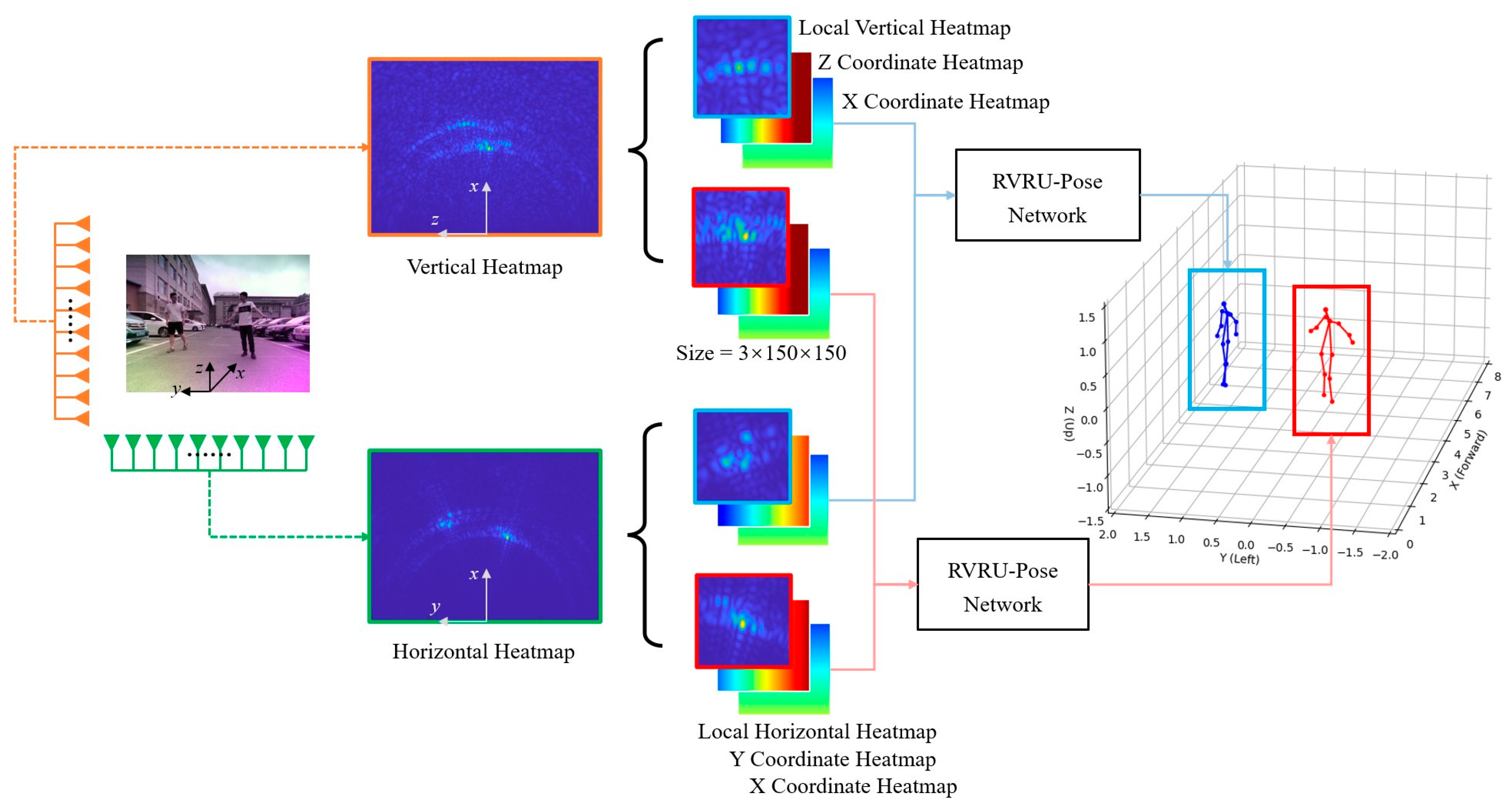
To achieve multi-target detection in distant and wide surveillance areas, this paper proposes a method that first detects the interested targets from radar heatmaps using a radar target detection algorithm. Then, skeleton pose estimation is performed individually on each target. The schematic diagram is shown in
Figure 2. There are two main approaches for radar target detection. The first approach is based on radar signal detection theory, which selects several target points from the radar heatmaps based on their intensity and performs clustering to distinguish multiple targets. However, this approach fails to differentiate between target types, whereas we are interested only in pedestrian targets. The second approach is based on deep learning, where models like YOLO [
31] are trained on radar heatmaps to achieve accurate detection and recognition of pedestrian targets. However, this method has higher computational complexity. In this paper, a combination of these two approaches is adopted. When there are only moving pedestrian targets in the scene, the first approach is used for target detection. When there are multiple types of moving targets in the scene, the second approach is employed.
After target detection, the centroid position of each target is selected, and a region of interest with dimensions of 2 m × 2 m × 2 m is extracted around the centroid. The spatial size of pedestrians is generally not larger than 2 m, so a size of 2 m is chosen as the dimension for the region of interest. The skeleton pose estimation is then performed on the radar sub-image of the region of interest instead of directly detecting the entire radar heatmap. However, the cropped radar sub-image loses the global localization information of the target. Taking inspiration from range–Doppler (RD) positioning in Synthetic Aperture Radar (SAR) imaging [
32], this paper also preserves the pixel position of the radar sub-image in the radar heatmap when cropping. Therefore, the input to the skeleton pose estimation network includes not only the cropped intensity heatmap but also the encoded heatmap of the cropping region coordinates.
4. Methodology
In this section, the pipeline of the proposed method is first given. Then, the cross-modal supervised network RVRU-Pose is illustrated. Finally, a multi-resolution data enhancement and training method for radar is proposed.
4.1. Method Pipeline
The complete process of the proposed method is shown in
Figure 3. It mainly includes four parts: Radar Signal Process, Targets Detection and Extraction, Teacher Network (OpenPose), and Student Network (RVRU-Pose).
In the training stage, the method of cross-modal supervised learning is used. In the open scenario, vulnerable road users such as humans are assigned as subjects. Then, the distributed radar and depth camera synchronously collect experimental data to obtain paired 3D optical image set
, horizontal radar image set
, and vertical radar image set
. For the 3D optical image dataset, the computer vision-based deep learning network OpenPose [
4] is first trained using 2D color images as the teacher network
to obtain heatmaps of the target skeletal joints. Then, the pixel coordinates of the skeletal joints in the color image are projected onto the depth image to obtain the 3D spatial coordinates
of the skeletal joints. By training the teacher network on the massive dataset,
has sufficient accuracy and robustness to automatically generate supervised labels for the student network. The student network
has a two-headed input, which is used to input the H radar image and coordinating heatmap sequence and V radar image and coordinating heatmap sequence, respectively, to obtain the 3D spatial coordinate
of the skeletal pose joints via regression. Then, the difference between the outputs of the teacher network and the student network is computed using the loss function
, and the model parameters of the student network are updated by stochastic optimization using the adaptive momentum method. During training, limited by the performance of the depth camera, the distance of the collected data generally does not exceed 5 m in order to ensure the accuracy of the results of the teacher network. However, practical road applications often require long-distance skeletal pose estimation. Therefore, we propose a multi-resolution radar image training method. Based on the relation between the radar angular resolution and the radar array aperture, the radar image of an equivalent distant target is intercepted by the aperture of the radar data, and then the coordinate heatmap is adjusted accordingly to achieve dataset augmentation. After training, accurate 3D skeletal pose estimation results can only be obtained by feeding the H and V radar image sequences into the student network.
4.2. Cross-Modal Supervised Network
In this section, a cross-modal supervised network named RVRU-Pose (Radar Vulnerable Road User Pose) is proposed for skeletal pose estimation. RVRU-Pose uses the radar heat map sequence from the horizontal and vertical radars as input through forked CNN architecture, and it uses data-driven regression to return the three-dimensional spatial coordinates of the skeletal postural joints.
The horizontal and vertical radar heatmaps obtained from the radar are three-channel images, where the three channels are the radar heatmaps of target, the radar forward coordinate heatmaps, and the radar transverse coordinate heatmaps. The size of radar heatmap is set to
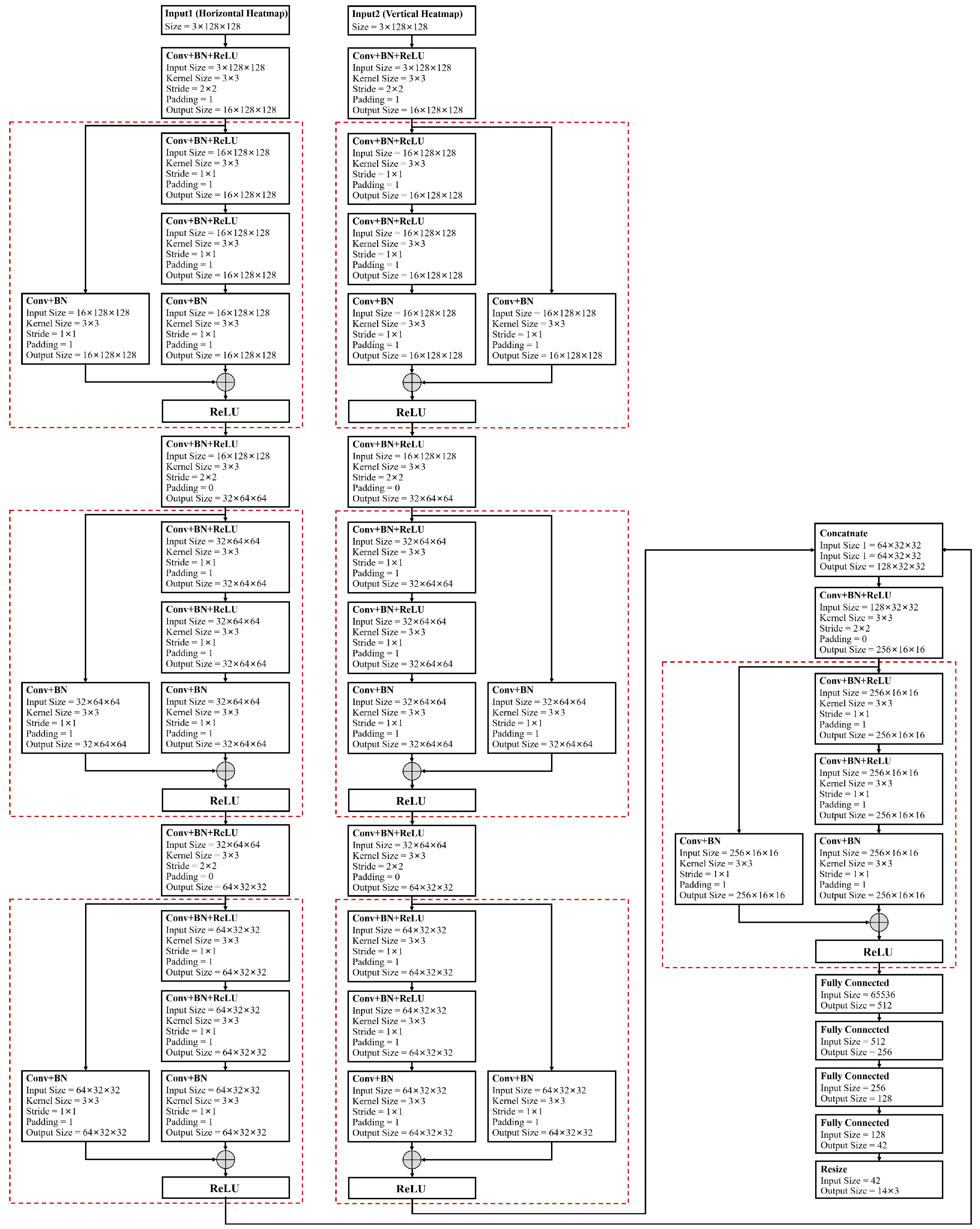
. The horizontal and vertical radar heatmap sequences are, respectively, fed into a multi-layer CNN channel with the same structure. The tensors after feature extraction are fused in the channel dimension, and then the combined features of the fused tensors are extracted by the multi-layer CNN channel. Finally, the tensor is expanded into vectors by a fully connected layer to form a mapping relation between the radar heatmap sequence and the 3D coordinates of the skeletal pose. The basic structure of the proposed RVRU-Pose network is illustrated in
Figure 4, while
Figure 5 exhibits the specific parameters of the RVRU-Pose network.
In the deep learning task of optical images, the deep features of an image can be extracted by multi-layer convolution. However, mmWave radar images suffer from issues such as poor angular resolution, sidelobes, and noise interference, which makes the design of mmWave radar deep learning networks different from traditional optical deep learning networks. For the design of deep learning networks, this paper analyzes and designs the convolutional receptive field and the number of convolutional layers by fully considering the characteristics of radar images.
The receptive field in a convolutional neural network represents the region of the input map corresponding to a pixel in the output feature map [
18]. If denotes the size of the convolution kernel in the i-th layer, is the step size, and is the receptive field size, then
For mmWave radar images, the relationship between sensitivity field and radar resolution must be balanced so that the extracted feature maps contain multiple radar resolution units and fully exploit the resolution information of the radar images. For the range or azimuthal dimension of the radar image, let the physical size corresponding to the receptive field of the radar image be L, and let the radar resolution be ; then, should be satisfied. Specifically, for the azimuthal resolution , where R is the range, is the wavelength, and D is the azimuthal aperture of the radar antenna. When the convolution kernel size is 3 and the step size is 1, the sensitivity field size of the n-th convolution layer is , and can be obtained according to the constraint , where is the radar azimuth resolution and is the actual length corresponding to an azimuth pixel in the radar image. It follows that the minimum depth n of the convolutional layer should satisfy . Based on the above principles and the adopted mmWave radar system, the convolutional layer number of RVRU-Pose is reasonably designed in this paper.
According to the above analysis, the low resolution of radar images prevents the number of convolutional layers from being too small. However, multi-layer convolution has two problems: namely, the gradient vanishing often faced by deep convolutional networks and the loss of raw information in radar images in deep feature extraction. Raw information such as the intensity contained in a radar image has a reference meaning for distinguishing sidelobes from noise interference. To combine deep and shallow features of radar images, the ResBlock module [
33] is introduced in this paper, as shown in
Figure 4.
4.3. Multi-Resolution Radar Imaging Training
The training of deep learning networks cannot be separated from large-scale datasets. The strategy of mmWave radar deep learning by using visual cross-modal supervised learning has been widely used in existing works. However, since visual sensors are mainly used for angular resolution, human skeletal pose detection based on visual sensors is generally used for relatively short distances. When the target is far away, the number of pixel units occupied by the target in the image decreases, making skeletal pose detection difficult. As a result, visual sensors can only automatically label datasets of close-range targets, and existing related works mainly focus on indoor close-range application scenarios, which do not leverage the advantages of mmWave radar for long-range detection.
In this paper, a dataset enhancement method based on multi-resolution radar images is proposed for deep learning training. Radar images of targets at different distances are generated by adjusting the radar angular resolution, and the optical detection of the human skeletal pose is shifted synchronously to the target distance for data augmentation.
Based on radar azimuthal resolution
where
is the azimuth resolution,
R is the radar detection range,
k is the constant 0.886,
is the wavelength,
D is the radar aperture of the array, and
n is the array element number of the uniform array with interval
d. It can be seen that increasing the distance
R and decreasing the number of elements
n can achieve an equivalent effect on reducing the azimuth angle resolution.
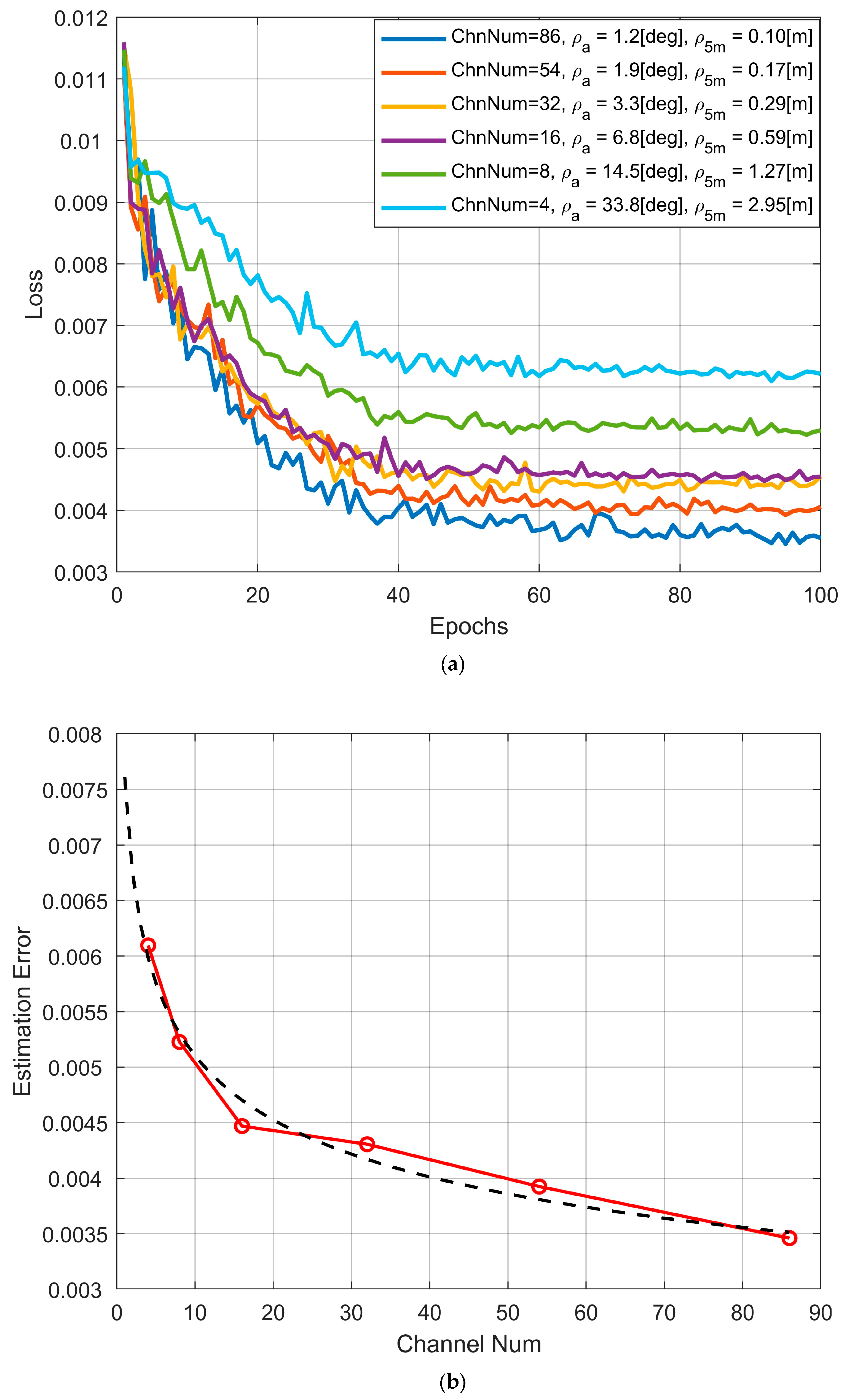
In the data acquisition step, the complete radar array is used to collect data within a certain close range, e.g., 3–8 m, where the optical sensor can work normally, and the optical image is automatically labeled. In the data processing step, different target distances can be simulated by selecting different radar apertures for multi-resolution imaging based on the equivalence between the m-fold reduction in array elements and the m-fold increase in range, as shown in
Figure 6. Human skeletal pose detection data suitable for remote targets can be constructed by jointly training on multiple resolution radar images.

