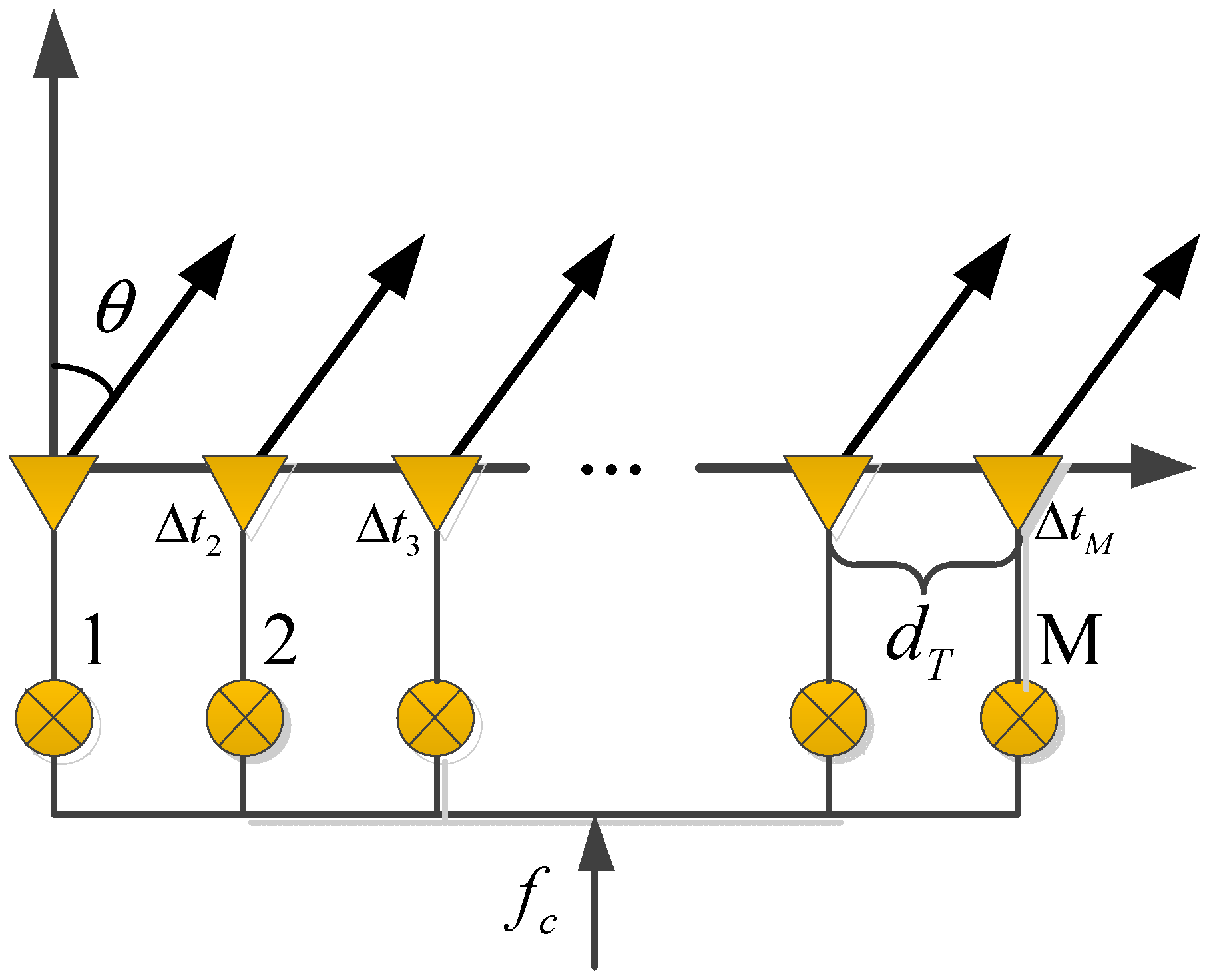
1. Introduction
Radar systems have been widely applied due to their all-weather and all-day detection ability. However, with the rapid development of scientific and technological levels, many new kinds of targets have emerged. The trend of new aerial targets is becoming more diversified, miniaturized, high-speed and covert, which will bring higher challenges to radar early-warning and detection technology. This requires the new radar system to have the continuous observation ability of forming multiple beams and various waveforms in different key areas at the same time, and should realize the flexible allocation of transmitting resources in airspace. With the development of digital beamforming technology and semiconductor device technology, digital array radar (DAR) comes into being [
1], which could fully realize digitalization at both the transmitting end and the receiving end. DAR has high application potential due to its advantages of multi-tasking, multi-mode model, and high degree of freedom [
2]. It will significantly promote the performance improvement of new radar systems.
Although the digital array radar has proved that it can realize full digitalization at both the transmitting end and the receiving end, the current research is basically focusing on the digital beamforming (DBF) at the receiving end, such as the commonly used mode with wide-beam transmitting and narrow-beam receiving (SIMO, Single-Input and Multi-Output), which only uses receiving DBF to realize multi-beam reception; and the MIMO (Multi-Input and Multi-Output) mode, with the orthogonality of the transmitting waveforms, which can be used to obtain effective transmitting DBF after signal processing at the receiver end, but it is not directly transmitting DBF [
3,
4]. The MIMO technique is widely applied in SAR (Synthetic Aperture Radar) especially, because it can break the constraint between azimuth resolution and range swath width [
5,
6,
7]. Both of the two modes mentioned above are omnidirectionally transmitting, but without the focus of transmitting resources to some directions that require key attention. It will lead to a waste of energy resources, and the signal-to-noise ratio, signal-to-clutter ratio, or other performance is not ideal. Therefore, the development of DBF at the transmitting end is far from mature, and the high degree of freedom at the transmitting end is waiting to be explored and utilized. The research of transmitting and receiving a fully digital array radar is greatly significant.
Multi-dimensional waveform coding array is a new concept developed on the basis of the MIMO radar, which can fully explore the degree of freedom at the transmitting end [
8]. Its connotation includes but is not limited to the generalized coding optimization design of the transmitting signal in terms of time domain, frequency domain, and array domain [
8,
9,
10]. Compared with the MIMO radar system, it has more advantages in gain consistency, low range sidelobe, engineering ease of implementation, and so on [
10]. In 2008, G. Krieger of DLR gave the following expression for the mathematical definition of multi-dimensional waveform coding array [
9]:
where
represents the transmitting original waveform,
and
represent the spatial gain coefficients of the transmitting and receiving arrays, respectively. The synthetic transmitting waveform
of multi-dimensional waveform coding array is space–time coupled and cannot be simply represented as the product of
with
and
. At present, the two most typical kinds of array sensors conforming to the concept of multi-dimensional waveform coding array are space–time coding array (STCA) and Frequency Diverse Array (FDA) [
11,
12,
13]. Their space–time/frequency coupling transmitting mechanism and flexible beam-scanning capability could provide a feasible solution for the multi-degree-of-freedom joint optimization design, which has great application potential in target detection, target tracking, and observation imaging.
Space–time coding (STC) for MIMO waveform design was introduced in References [
14,
15,
16,
17] to introduce a further degree of freedom at the transmitting end. The Chevalier team first proposed the concept of STCA [
18], which uses single waveforms and introduces a small time delay between array elements, and then the whole space coverage of transmitting can be realized [
19]. It was also called colored transmission in [
18]; the principle of colored transmission consists of simultaneously transmitting different waveforms in different directions. The directivity and high degree of freedom on transmit is then recovered by signal processing on the receiving end. The transmitting DBF capability is utilized to make up the deficiency of receiving DBF. Reference [
20] demonstrated that STCA has the characteristics of good energy consistence of the pattern, simple system structure, controllable Doppler tolerance, and so on.
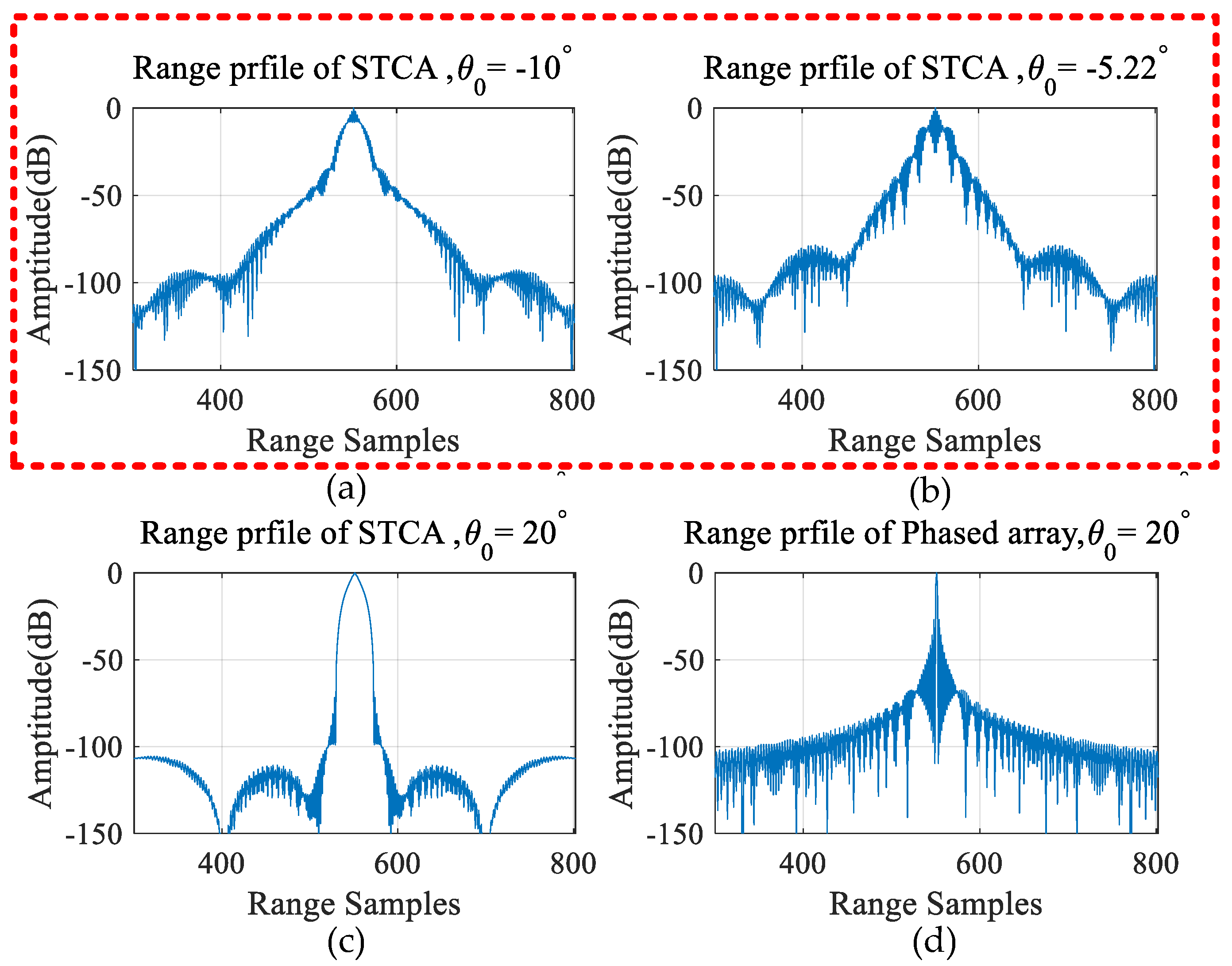
However, the adoption of STCA will bring some problems. Firstly, it will cause the loss of range resolution because it sacrifices part of the resolution to obtain the spatial scanning coverage capability and ultra-low sidelobe [
18,
21,
22,
23]. In order to solve it, Reference [
24] proposed a hybrid coding combining STAC and spatial coding. Reference [
25] proposed a hybrid coding combining STAC and slow-time coding. Reference [
26] optimized the range sidelobe of STCA by subarray partitioning. However, there is a contradiction between the width of the mainlobe and the level of the sidelobe; the resolution recovery will bring the increase in the sidelobe level [
24,
25,
27]. So, we need to further optimize the sidelobe performance after resolution recovery.
Secondly, Reference [
28] pointed out the inherent resonance problem of STCA, which is caused by the spectrum discontinuity at the beginning and end during beam scanning, resulting in a mismatch at some specific angles, and then the phase correction method was proposed to solve this problem [
28]. But it will be inapplicable if the whole space observation is required.
So, the motivation of our work is to solve the two sidelobe problems of STCA: deterioration of the sidelobe due to the resolution recovery, and the inherent resonance problem. In this paper, array element spatial coding is applied at the transmitting end to recover the resolution and solve the resonance problem. The mismatched filter (MSF) design at the receiving end is applied to further optimize sidelobe performance. MSF is a popular method to optimize the sidelobe [
29,
30,
31,
32]. Cilliers designed MSF based on p-norm, minimizing the integrated sidelobe level or peak sidelobe level [
33]. De Maio used QCQP (quadratic constrained quadratic programming) and other convex optimization methods to design MSF, and the influence of filter length or other factors on the sidelobe suppression effect was studied [
34,
35,
36]. Jiu realized the great improvement of SNR by carrying out the joint design of emission waveform and MSF [
37]. Zhou realized sidelobe reduction and SAR anti-ISRJ (Interrupted-Sampling Repeater Jamming) through the joint optimization of transmitting waveform and MSF design on receive [
38,
39,
40]. Yu proposed the low peak sidelobe level (PSL) MSF designed for an FDA radar, which can be further modified to improve the clutter suppression performance and Doppler tolerance performance [
41]. However, for the STCA, the normal MSF design method is not applicable since the waveform is space–time coupled. Therefore, an improved space–time MSF optimization model is established in this paper to design an MSF that is applicable to STCA.
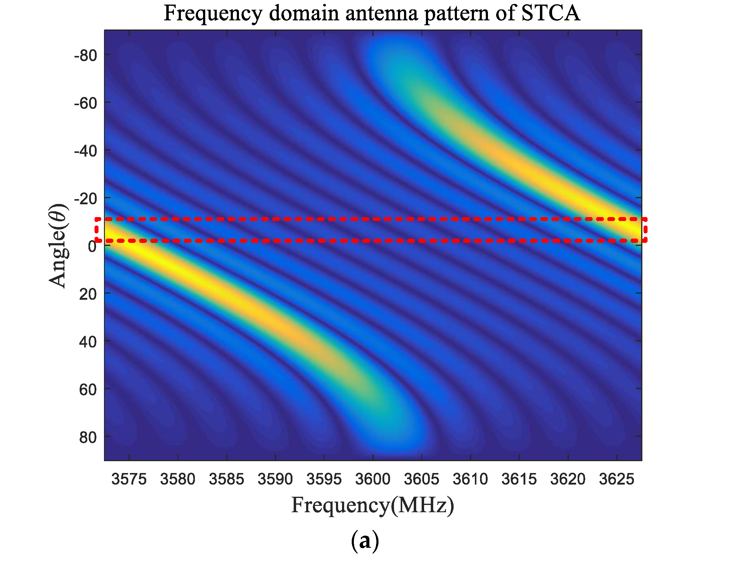
Above all, in this manuscript, firstly, the brief signal model and array characteristics of STCA are analyzed, and then we point out that there are two key problems in the sidelobe of STCA. One is the inherent resonance effect in STCA, which is caused by the spectrum discontinuity at the beginning and end of the pulse, resulting in sidelobe deterioration at some specific angles [
28]. This phenomenon has negative effects in practical engineering applications. The second problem is deterioration of the sidelobe due to the resolution recovery, because STCA sacrifices part of the range resolution to obtain the spatial scanning coverage capability and ultra-low sidelobe, so the issue of how to restore the resolution under the premise of maintaining the whole spatial coverage capability and low sidelobe is also a key research point. Then, the multi-dimensional ambiguity function is proposed as the performance evaluation tool. In order to solve these two problems, this manuscript proposes an optimization method with the combination of array element spatial coding at the transmitting end and an MSF optimization design at the receiving end, which can solve the inherent resonance problem and improve the rang resolution while the spatial scanning capability and low sidelobe level of STAC can still be maintained.
Section 1 is the research background and introduction of our research content.
Section 2 is the basic introduction of the signal model and characteristics of STCA, and then it introduces the two key problems of sidelobe of the STCA that we want to solve, which is the motivation of our work.
Section 3 proposes the multi-dimensional ambiguity function that is the evaluation tool for STAC.
Section 4 proposes the joint optimization method and introduces it in detail.
Section 5 is the simulation verification, performed through software simulation and comparative quantitative analysis, to verify the effectiveness and optimization effect of the proposed method.
Section 6 is a discussion of the simulation results and proposes the further research direction.
Section 7 is a summary of the main work in this manuscript, which then points out the problems that exist and explains the ideas for our further research.
3. Evaluation Tool
As a powerful tool to evaluate the range and Doppler resolution of a transmitting waveform, an ambiguity function reveals the inherent ambiguous characteristics. However, the conventional ambiguity function only focuses on the range and Doppler characteristics of the transmitting waveform, and does not consider the multi-dimensional coupling characteristic of STCA. Therefore, based on the traditional ambiguity function, we introduce the steering vector to obtain the multi-dimensional ambiguity function, which not only expands the resolution ability of the conventional ambiguity function in the angle dimension, but also can represent the spatial focusing ability of the STCA. The multi-dimensional ambiguity function is more suitable for evaluating the transmitted waveform of the STCA, which is specifically defined in Equation (14) below.
where
and
are transmitting signals of the
m-th and
n-th array element,
is the angle of the target,
is the angle of the equivalent transmitting DBF, which is the angle during STCA scanning.
is the time delay in range domain;
is the Doppler frequency in Doppler domain;
is the distance between the adjacent array elements. Term 1 evaluates the spatial focusing performance of the array radar; term 2 is similar to the conventional ambiguity function that can evaluate the autocorrelation performance and Doppler tolerance of the transmitting waveform.
Due to the high dimension of multi-dimensional ambiguity function, it is not easy to analyze directly, so different dimensional reduced expressions are usually used to evaluate the performance. Several commonly used dimensional reduced expressions are as follows:
1). Range–angle ambiguity function represents the resolution of the waveform to target at a different angle under the condition of zero Doppler and the fixed transmitting DBF angle ;
2). Angle–angle ambiguity function represents the spatial coverage capability of the transmitting waveform under the condition of ;
3). Range–Doppler ambiguity function can evaluate the autocorrelation performance and Doppler tolerance of the transmitting waveform.
The following
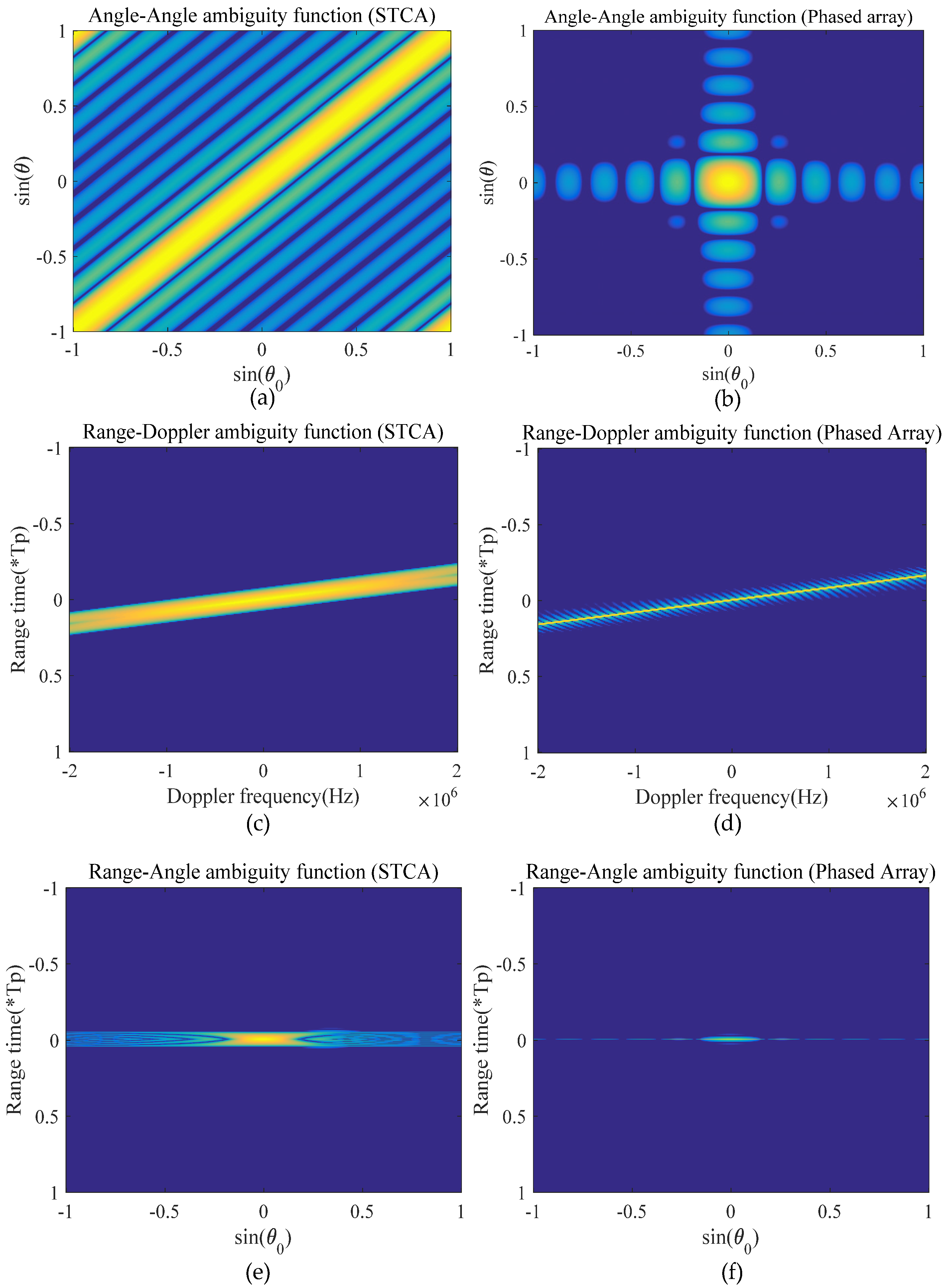
Figure 4 is a comparison diagram of multi-dimensional ambiguity function evaluation between STCA and the traditional phased array.
In
Figure 4a,b, the fluctuation along the main diagonal physically stands for the difference in transmitting gain. The energy is uniformly distributed on the main diagonal for STCA, which reflects the spatial scanning capability and gain consistency of STCA. However, for the phased array, we can see that the energy is mainly concentrated near the beam center, and it has no spatial scanning coverage capability. In
Figure 4c,d, we can see that the Doppler tolerance performance of STCA and the phased array are both satisfactory when transmitting the LFM signal. Simultaneously, the vertical profile can also reflect the autocorrelation performance in conditions of different Doppler frequencies, and we can find that STCA will bring significant mainlobe widening. In
Figure 4e,f, the vertical profile can reflect the imaging performance in different angular directions, and we can find that STCA has a lower sidelobe but a wider mainlobe compared with the phased array. These figures could verify our theoretical analysis. STCA has spatial scanning capability and ultra-low sidelobe, but it will bring an obvious mainlobe broadening; the resolution deteriorates significantly, which will be solved in the following sections.
4. Proposed Method
In order to solve the problems outlined in
Section 2, an improved optimization method is proposed here.
When transmitting, we can change the pattern of the transmitting array by introducing the array element spatial code between transmitting array elements. The signal with spatial code is given by the following:
where
is the array element spatial code. The scanning capability of STCA can still be maintained since it is a time-invariant code. The Barker code is a typical kind of array element spatial coding, which is an aperiodic binary code with a special law. Each element can only take the value +1 or −1 [
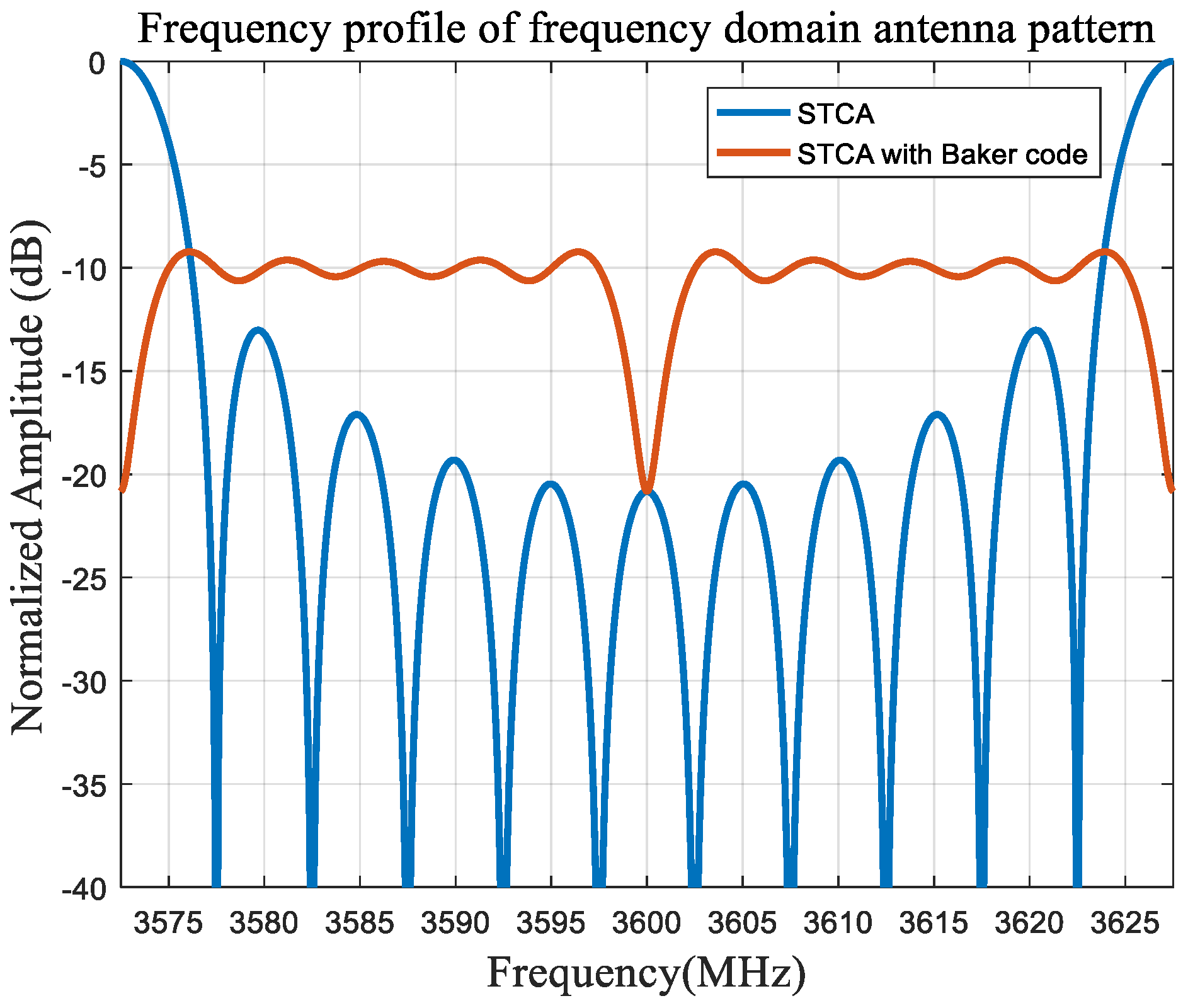
24]. Similarly, the frequency profile of antenna pattern of STCA with the Barker code is shown below in
Figure 5.
We can clearly see that the mainlobe of the frequency window can be compressed. It makes the frequency window more flat and uniform, so the frequency covered in each direction is almost recovered to whole bandwidth, and the spectrum discontinuity and mismatch caused by the “sliding window” effect can be greatly alleviated. Therefore, the resolution problem and resonance problem can be solved.
However, because the mainlobe is compressed, it will bring the decrease in the mainlobe and the increase in the sidelobe level. Therefore, at the receiving end, the MSF is designed to optimize the sidelobe level further.
Matched filter (MF) is widely used in the field of radar. According to the detection theory, it has been verified that the performance of MF for detecting a single target in the case of Gaussian white noise is optimal, and the maximum processing gain can be obtained. But it also brings a higher sidelobe, so in the case of multiple targets, the weak targets are likely to be submerged by the sidelobe of the strong targets, so many scholars have studied the mismatched filter (MSF) [
27,
28,
29,
30,
31,
32,
33,
34,
35,
36,
37,
38,
39,
40,
41,
42]. However, for the STCA, the normal MSF design method is not applicable since the waveform is space–time coupled.
Therefore, in the STCA system, the MSF design needs to consider the space factor. The improved convolution matrix is as follows:
where
is the
n-th element of the signal vector, which is the discrete form of
in Equation (15). Then the output of MSF is as follows:
where
is the filter vector of length
, so the output is a vector of length
, for convenience assuming
, so that
is guaranteed to be an odd number, the peak value of the convolution output will appear at the position of
.
So, the PSLR (Peak to Sidelobe Ratio) constraint is set as follows:
where
is the
-th row of matrix
. Simultaneously, because the matched filter maximizes the SNR (signal-to-noise ratio) at the peak, the MSF will bring the LPG (loss-in-processing gain) at the peak [
35,
36], which is defined as the ratio of the MSF’s SNR to the MF’s SNR, so we need to add the LPG constraint:
The threshold
is a real constant between 0 and 1, and it is used to limit the LPG. At the same time, we need to ensure the energy unity of the MF and the MSF:
Here, we assume that the energy of MF is
N, so the optimization model established is as follows:
This optimization model mainly restricts LPG and PSLR. However, it can be found that this QCQP (quadratically constrained quadratic programming) problem is not a convex optimization problem, so it requires a large amount of computation to solve. In order to reduce the computation, we consider transforming it to a SOCP (second-order cone programming) problem through relaxing these constraints to a certain extent under the real number condition and controlling the loss of optimization performance at an ideal level simultaneously [
42].
To transform the QCQP problem to the SOCP problem, we first need to convert the parameters into the real number:
At the same time, the constraints also need to be relaxed. The energy constraint is adjusted to the following:
The LPG constraint is adjusted to the following:
The PSLR constraint is adjusted to the following:
So, the SOCP optimization model is as follows:
After the real parts and imaginary parts of the optimal filter sequence are obtained, the complex filter sequence
can be obtained by a recombination of two parts, and this is the MSF actually used. But because of the relaxation in the energy constraint, a step of energy normalization is also needed here:
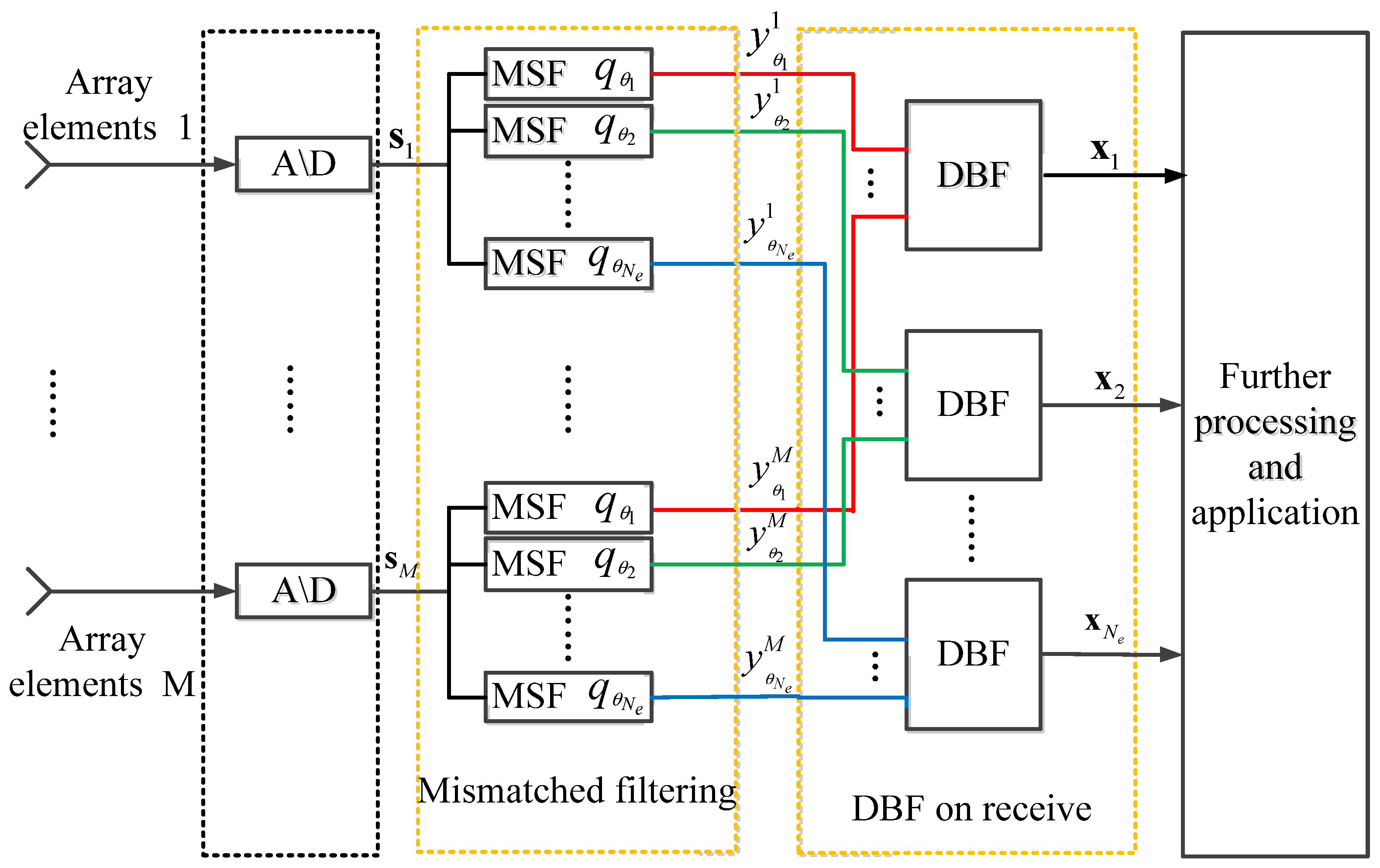
So, the improved signal processing structure of the receiving end for STCA is shown in following
Figure 6:
Each receiving channel is the superposition of echoes from different directions, so for each receiving channel, Ne space–time MSFs are required, where Ne is the number of directions of interest in our observation. Then, Ne*M groups of output signals will be used for the receiving DBF processing, and then Ne groups of output signals will be used for further application.
5. Simulation
In this part, the multi-dimensional ambiguity function mentioned in
Section 3 is applied as the evaluation tool. The Matlab R2016a is used to carry software simulation to verify the effectiveness and feasibility of the proposed optimization method. We mainly focus on the range–angle ambiguity function and the range profile of it.
The main simulation parameters are set as
Table 1 below:
According to the analysis in
Section 2, under this parameter setting, the resonance effect will occur at
and its adjacent angle region. So firstly, we observe the range–angle ambiguity function at
of normal STCA and STCA using the proposed optimization method. The simulation results are shown in
Figure 7 below:
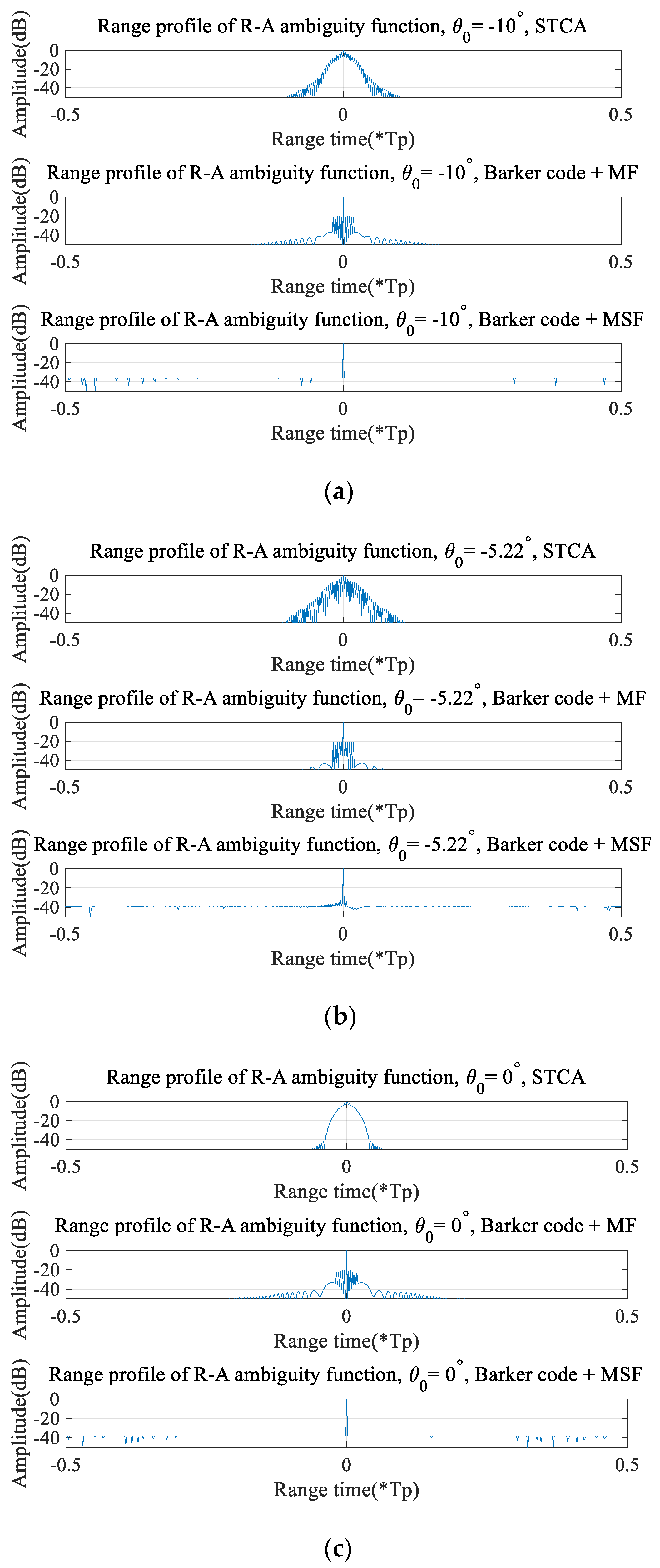
Figure 7 show the range–angle ambiguity function of normal STCA and STCA applying the proposed method; it can show that the resolution loss problem and resonance problem of STCA can be completely solved, and the sidelobe performance at the expected direction is greatly improved through using the proposed method. In order to be more intuitive, we observe the range profile of the expected direction, as shown in
Figure 8 below:
Figure 8 is the range profile of three modes: the ordinary STCA system, the STCA system with the Barker code and MF, and the STCA system with the Barker code and MSF. It can be seen that after adding the Barker code, the resolution is recovered and the resonance problem is solved. But it will bring a significant increase in the sidelobe level, so the MSF optimization method is further processed at the receiving end. It can be seen that after MSF processing, the sidelobe level has been significantly optimized and can be maintained at an ideal level on the basis of maintaining the resolution.
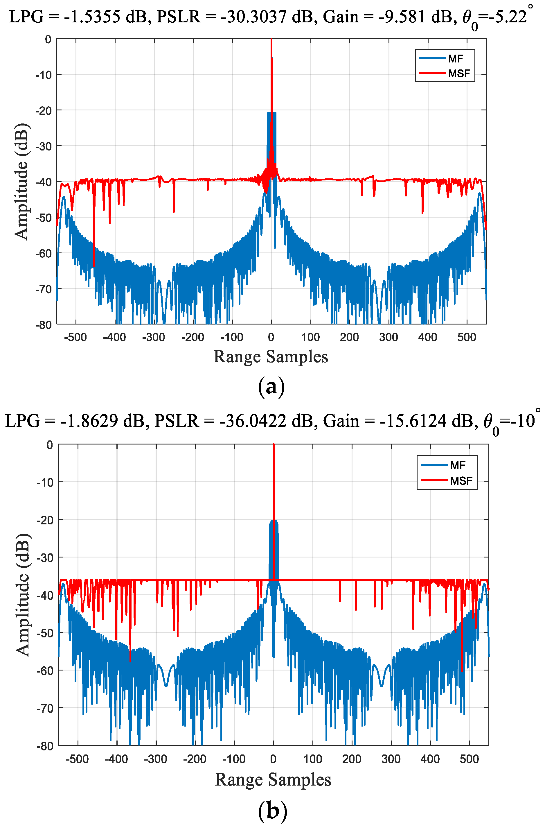
Then, we further compare the results of the MSF and MF to show the optimization effect of MSF, and the results are shown in
Figure 9 below.
It can be seen in
Figure 9 that through solving the SOCP problem that containing LPG and PSLR constraints can optimize the PSLR under the premise of accepting a certain degree of LPG at the peak. In order to get more accurate conclusions, we select multiple directions for quantitative analysis to verify the optimization effect of MSF.. The results are shown in
Table 2 below:
It can be seen that through the proposed MSF optimization method, the PSLR can be reduced by at least 10 dB, and even close to 20 dB at some angles, while the LPG can be controlled no more than 2 dB. Through image comparison and quantitative analysis, the optimization of the MSF at the receiving end is further verified.
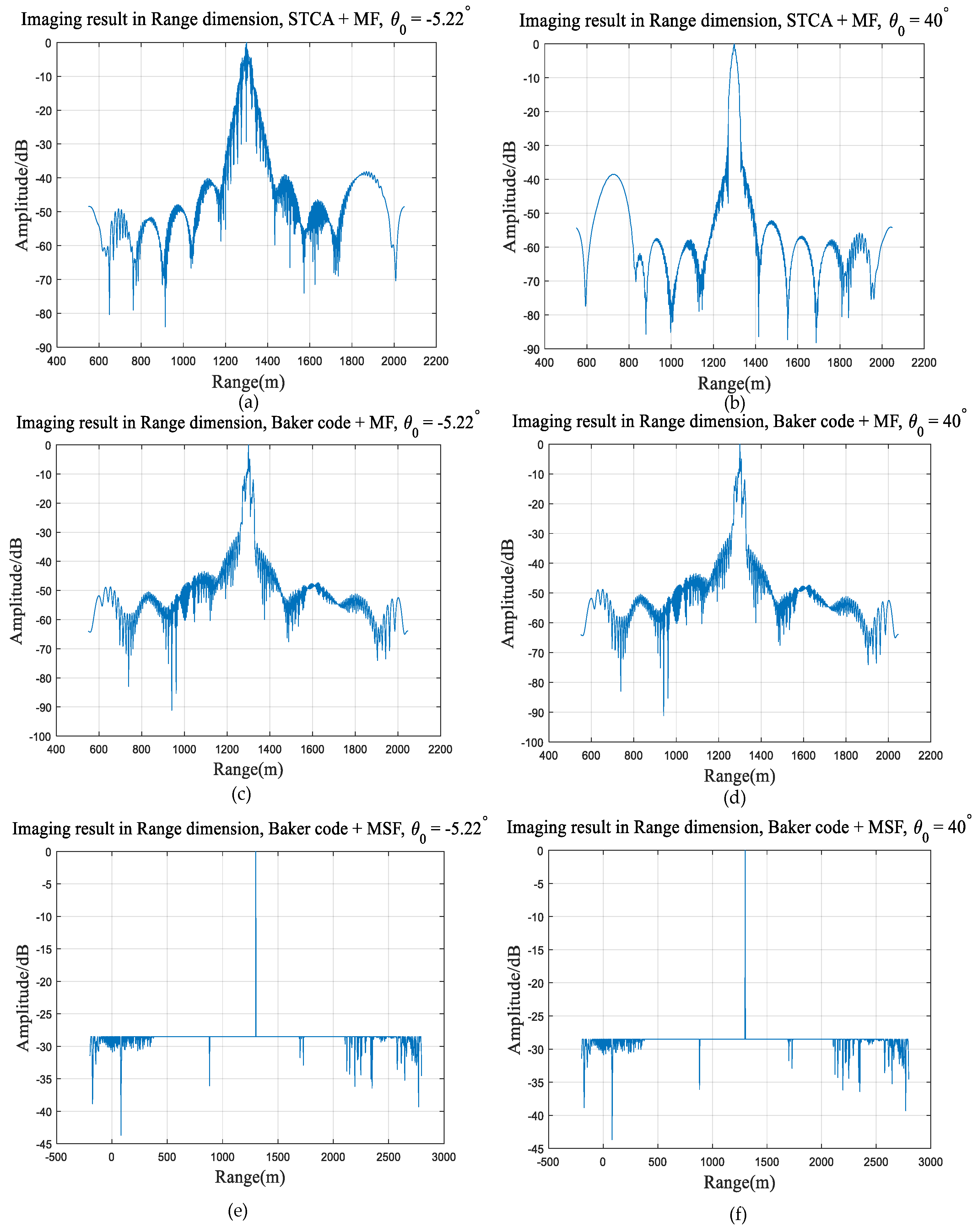
All of the above are model-level simulation experiments. In order to verify the practical feasibility, we also carry out a simple point target simulation experiment. The system parameters are set as the same as
Table 1. Two point targets are set as A1 (1300,
), A2 (1300,
); in parentheses, the former is the range value of the target, and the latter is the angle of the direction of the target. According to our previous analysis, target A1 is within the resonance angle region and target A2 is not. The point target simulation results are shown in
Figure 10 below:
First, echo simulation and imaging processing were carried out for the normal STCA, as shown in
Figure 10a,b. In accordance with our theoretical analysis, there is an obvious resonance phenomenon at the resonance angle
; however, the ideal imaging result is obtained in the direction far away from the resonance angle.
Figure 10c,d show the imaging result of STCA with the Barker code and MF; it can be seen that through adding the Barker code, we can eliminate the resonance phenomenon and recover the resolution. But the sidelobe will increase at the same time, so the MSF optimization method is applied at the receiving end.
Figure 10e,f show the imaging result of STCA with the Barker code and MSF. The performance of the range sidelobe can be optimized by combining the Barker code at transmitting and MSF at receiving, so the sidelobe is reduced and maintained at an ideal level. This simple point target experiment is completely consistent with our analysis and simulation conclusions, which can prove the effectiveness of the proposed optimization method. Our team is also currently developing an actual prototype of the STCA, which will be used for more rigorous and complex practical experiments.
Above all, the effectiveness of the proposed sidelobe optimization method is proved. The resonance problem of STCA can be eliminated, the lost resolution is recovered, and the sidelobe is optimized and maintained at an ideal level while the spatial scanning capability is maintained.
6. Discussion
The main work of this paper is performed to optimize the sidelobe problems of STCA: the resonance phenomenon and the resolution loss problem. An optimization method combining array element spatial coding at the transmitter and mismatched filtering at the receiver is proposed. In the simulation, the multi-dimensional ambiguity function is applied as the evaluation tool.
Firstly, the range–angle ambiguity function is drawn in
Figure 7. We can see that in our expected angle, the range mainlobe width is obviously compressed and the resolution is recovered. The resonance phenomenon shown in
Figure 7a is also eliminated. This simulation can prove the optimization effect of the proposed method. Then, in order to see the results more clearly, we mainly focus on the range profile in different directions, as shown in
Figure 8. We compare the following three modes: normal STCA, STCA with the Barker code and MF, and STCA with the Barker code and MSF. It can be concluded that after using the Barker code, the resolution can be recovered and the resonance problem can be solved. However, it will bring an increase in the sidelobe. The MSF processing at the receiver can further optimize the sidelobe level while the resolution is maintained.
Figure 8 can prove the effectiveness of the proposed method, especially the array element spatial code. Then, we further use the statistical method to quantitatively analyze the optimization effect of MSF at the receiving end.
Figure 9 shows that the sidelobe level is significantly reduced and maintained at the ideal level, with the application of MSF compared with MF.
Table 2 shows the PSLR and LPG of different directions after MSF processing. At
, LPG is −1.89 dB and PSLR is −37.48 dB, which is 17.26 dB lower than MF; at
, LPG is −1.86 dB and PSLR is −36.04 dB, which is 15.64 dB lower than MF; at
, LPG is −1.54 dB and PSLR is −30.30 dB, which is 9.58 dB lower than MF; at
, LPG is −1.95 dB and PSLR is −38.30 dB, which is 17.78 dB lower than MF; at
, LPG is −1.97 dB and PSLR is −38.27 dB, which is 18.69 dB lower than MF; at
, LPG is −1.96 dB and PSLR is −38.44 dB, which is 18.57 dB lower than MF. Through the proposed MSF optimization, the PSLR can be reduced by at least 10 dB while the LPG can be controlled below 2 dB. Finally, a simple point target simulation is carried out to verify the proposed method experimentally, and the imaging results shown in
Figure 10 are consistent with our theoretical expectation. This can prove the effectiveness of the proposed MSF processing.
In summary, through a simulation image comparison and quantitative analysis, we fully verify the optimization effect of the proposed method for STCA. The two sidelobe problems can be solved while the spatial scanning ability of STCA can be maintained. Of course, our work can still be improved. Because of the space–time coupling characteristic of STCA, it has not only the time sidelobe that we optimize in this paper, but also the space sidelobe.
Figure 7 shows that the proposed method can only optimize the range sidelobe of a specific direction; once the angle is slightly off, the optimization effect will be obviously worse. This also can be called the “Angular sensitivity” of STCA. We hope that an MSF can achieve a good optimization effect in an angular mainlobe, which is our next research direction.
7. Conclusions
The main goal of this paper is to study the optimization method of STCA, aiming at the two key problems of the resonance phenomenon and the resolution loss problem of STCA. A joint optimization method is proposed. At the transmitting end, the array spatial coding is used to adjust the array pattern to achieve resolution recovery and eliminate the inherent resonance problem in some specific angle regions. But it will bring obvious deterioration of the range sidelobe performance, so the method of mismatched filter design is used at the receiving end to further optimize the sidelobe performance. By setting suitable LPG and PSLR constraints, the optimal sidelobe level can be achieved by sacrificing part of the gain at the peak. The experimental analysis and quantitative comparison also show that the sidelobe performance of STCA is significantly optimized through the proposed joint optimization method. The resonance problem and the resolution loss problem are eliminated, while the PSLR is reduced to the ideal level, which reflects the effectiveness of the proposed method. This proposed method has certain significance for the performance optimization of the STCA radar system, which has application potential in Earth imaging and target detection or tracking.
Of course, the research in this paper can be further studied. Firstly, the optimization of the mismatched filter is not only limited to PSLR, but also can optimize other performances by adding other appropriate constraints. For example, adding integral sidelobe ratio constraint can control the ISLR; adding angle constraint can suppress the clutter signal from the known direction; and adding Doppler constraint can improve the Doppler tolerance of the radar system. The radar performance can be further improved by the mismatched filter design. Secondly, the main work in this paper is performed to optimize the range sidelobe performance of STCA. At the same time, the STCA also has the angular sidelobe in space domain due to its space–time coupling characteristics. The next step is to conduct in-depth research on the space–time coupling sidelobe, optimize the spatial angle sensitivity of the STCA, and further improve the radar system.
