Article

The Loran-C Pseudorange Positioning and Timing Algorithm Based on the Vincenty Formula

by
Jingling Li
1,2 and
Huabing Wu
1,3,*
1
National Time Service Center, Chinese Academy of Sciences, Xi’an 710600, China
2
University of Chinese Academy of Sciences, Beijing 100049, China
3
Key Laboratory of Time Reference and Applications, Chinese Academy of Sciences, Xi’an 710600, China
*
Author to whom correspondence should be addressed.
Remote Sens. 2024, 16(17), 3227; https://doi.org/10.3390/rs16173227
Submission received: 3 August 2024 / Revised: 29 August 2024 / Accepted: 29 August 2024 / Published: 31 August 2024

Abstract

:
To improve the positioning accuracy of the Loran system and meet the requirements of Loran/BDS integrated positioning and timing, it is necessary to enhance the traditional Loran hyperbolic positioning method, making its pseudorange calculation consistent with the BDS positioning and timing solution. The existing pseudorange algorithm based on the Andoyer-Lambert formula has issues such as strict initial value selection range and susceptibility to singularities during calculations. This study proposes a new Loran pseudorange calculation method based on the Vincenty distance formula and conducts a simulation analysis of it. The results show that, in the absence of noise interference, the positioning and timing errors of this pseudorange algorithm are close to zero, demonstrating high accuracy. When subjected to random noise with a standard deviation of less than 100 ns, the latitude and longitude errors are both less than 10 m, and the timing error is less than 10−4 ns, meeting the requirements of Loran positioning and timing. Compared to the pseudorange algorithm based on the Andoyer-Lambert formula, the one based on the Vincenty formula has comparable positioning longitude accuracy but superior timing accuracy. Moreover, the latter offers a wider range of initial value selection and can avoid more singularity issues during calculations.

1. Introduction

Since the BeiDou Navigation Satellite System (BDS) officially began operating in July 2020, it has met the performance requirements for positioning, navigation, timing, satellite-based augmentation, precise point positioning, regional short-message communication, global short-message communication, and international search-and-rescue services [1,2]. However, like other Global Navigation Satellite Systems (GNSSs), the BDS is subject to various degrees of interference, which can render its services unreliable or unavailable. According to statistical data [3], the GPS system experiences interference on average 9 days per year, affecting 980 ships, 2144 aircraft, and 2121 mobile communication base stations.
To address the vulnerability of individual satellite systems to interference, various countries have proposed resilient PNT (Positioning, Navigation, and Timing) models. Academician Yang highlighted that the basic concept of resilient PNT is based on comprehensive PNT, which optimizes the integration of multi-source PNT sensors [4]. It utilizes the elastic adjustment of functional models and elastic optimization of stochastic models to generate PNT information that adapts to various complex environments, ensuring high availability, continuity, and reliability. A new report on the “Resilient PNT Reference Architecture” in the United States indicates that the resilient nature of PNT implies the ability to adapt to changing conditions, with the capability to respond to and quickly recover from disruptions [5]. Integrating GNSS with Loran-C for positioning and timing is a means of achieving resilient PNT.
Therefore, establishing a backup system for GNSS is crucial [6]. The 33rd Digital Avionics Systems Conference (DASC) highlighted the necessity of developing a long-wave system as a backup to address GNSS signal anomalies [7].
Loran is a terrestrial navigation system developed to provide precise location and timing information for maritime and aviation use [8]. Its construction history dates back to World War II, when it was initially developed by the United States for military purposes. The first operational Loran system, known as Loran-A, was deployed in 1942. Subsequently, the more advanced Loran-C system was introduced in the late 1950s and became widely used for civilian navigation [9].
The Loran system operates by transmitting low-frequency radio signals from a network of ground-based stations [10]. These signals are synchronized and pulsed at precise intervals. A Loran receiver on a vessel or aircraft measures the time difference between the reception of signals from multiple stations to determine its position. This is achieved through a technique known as hyperbolic navigation, where the intersection of hyperbolic lines of position, derived from time difference measurements, pinpoints the receiver’s location.
The Loran signal propagation relies on ground waves, which follow the curvature of the Earth, and sky waves, which reflect off the ionosphere [11]. Ground wave propagation ensures relatively stable and consistent signals over long distances, especially over water, while sky wave propagation can extend the range but introduces greater variability due to atmospheric conditions.
The accuracy of the Loran system is influenced by various types of errors, including Primary Factor (PF), Secondary Factor (SF), and Additional Secondary Factor (ASF) errors. These errors are caused by factors, such as signal propagation variability, multipath interference, geometric dilution of precision, and timing errors. These errors affect the precision of the time difference measurements, which are crucial for determining the receiver’s position [12].
Internationally, the Loran system is widely regarded as the most suitable backup for satellite-based navigation and timing systems for three main reasons [13,14,15]:
  • Independence: The Loran system is a land-based navigation and timing system, entirely different and independent from satellite-based systems. This independence reduces the likelihood of simultaneous failures since they are not susceptible to the same types of interference or failures;
  • Low-frequency signals: Loran’s navigation positioning signals operate at a lower frequency, around 100 kHz. Compared to satellite-based systems, these low-frequency signals have stronger diffraction capabilities, allowing for better penetration through obstacles and harsh environments, thus providing more reliable navigation and timing;
  • High power: The Loran system transmits signals at very high power levels, reaching up to megawatts. In contrast, satellite-based systems use lower-power signals. High-power signals have superior anti-interference capabilities, enhancing system reliability.
However, the traditional Loran system’s positioning and timing accuracy is relatively low and insufficient for current needs [16,17].
The hyperbolic positioning method of the Loran system is its core positioning technology. It determines the receiver’s position by measuring the Time Difference of Arrival (TDOA) of signals from multiple transmitting stations. The Loran system consists of a master station and several secondary stations. The master station transmits a reference signal, and each secondary station transmits signals sequentially after predetermined time delays. All signals use the same frequency and pulse format. The receiver captures signals from both the master and secondary stations and measures the TDOA of these signals. Since the propagation paths of the signals differ, the times at which the signals are received also differ. By using a precise clock, the receiver can record these time differences. Each time difference corresponds to a hyperbolic line of position, where every point on the line represents a constant distance difference between two transmitting stations. The receiver’s location is at the intersection of multiple hyperbolic lines. By solving these hyperbolic equations, the receiver’s exact position can be determined.
Since the traditional Loran-C positioning method uses hyperbolic positioning [17,18,19,20], which differs from the pseudorange calculation algorithm used in satellite positioning, it is necessary to research the Loran-C pseudorange positioning calculation method to achieve integrated positioning with BDS and Loran-C. To address these issues, Yan et al. [18,19] proposed a Loran-C positioning and timing method based on the Andoyer-Lambert pseudorange formula. This method analyzes the impact of random noise, secondary time delay, and other factors on positioning and timing results using basic pseudorange observations. It overcomes the limitations of station chains and provides relatively accurate results in the absence of observation errors. Although this method delivers precise positioning, it has limitations such as a strict initial value selection range and susceptibility to singular values in calculations. This may cause the iteration to not converge or converge to an erroneous value, resulting in the user being unable to obtain the correct position.
Therefore, in order to improve the availability of the positioning algorithm and reduce the impact of solving singular values or non-convergence of the solution, this study proposes a new pseudorange calculation method based on the Andoyer-Lambert formula. This method uses the Vincenty formula [20], which offers higher ranging accuracy, avoids singular values in the results, and provides precise positioning and timing. This approach unifies the calculation frameworks of BDS and Loran-C, supporting integrated positioning calculations.

2. Principle of Distance Measurement

The positioning principle of satellite systems [21] involves obtaining the positional information of each satellite (xi, yi, zi) and the distance ρi from each satellite to the receiver. With each satellite’s position as the center and the distance as the radius, circles are drawn, and the intersection of all circles represents the receiver’s position [22]. The pseudorange equation can be expressed as
ρ i = ( x i x r ) 2 + ( y i y r ) 2 + ( z i z r ) 2 + c Δ t + ε i
where ρi is the pseudorange from the receiver to the i-th satellite, (xi, yi, zi) are the coordinates of the i-th satellite at a known time, (xr, yr, zr) are the coordinates of the receiver’s position (unknown), c is the speed of light (approximately 299,792,458 m/s), Δt is the receiver’s clock bias, and ϵ represents other errors, including multipath effects and atmospheric delays.
Figure 1 illustrates the principle of positioning using four GNSS satellites. Since there are four unknowns in the GNSS pseudorange equations—x, y, z, and t—at least four equations are needed to form the equation set. This means that at least four satellites are required. Each satellite serves as the center of a sphere, with the distance from the satellite to the receiver as the radius. The intersection point of the surfaces of the four spheres represents the position of the receiver.
Since there are four unknowns in the equation, at least four satellites are required for simultaneous calculation [2]:
ρ 1 = ( x 1 x r ) 2 + ( y 1 y r ) 2 + ( z 1 z r ) 2 + c Δ t + ε 1 ρ 2 = ( x 2 x r ) 2 + ( y 2 y r ) 2 + ( z 2 z r ) 2 + c Δ t + ε 2 ρ 3 = ( x 3 x r ) 2 + ( y 3 y r ) 2 + ( z 3 z r ) 2 + c Δ t + ε 3 ρ 4 = ( x 4 x r ) 2 + ( y 4 y r ) 2 + ( z 4 z r ) 2 + c Δ t + ε 4
For each pseudorange equation, perform a first-order Taylor expansion and take its partial derivatives:
ρ i x r = x r 0 x i ρ i 0 ρ i y r = y r 0 y i ρ i 0 ρ i z r = z r 0 z i ρ i 0 ρ i Δ t = c
This converts the equation into a linear form:
Δ ρ 1 Δ ρ 2 Δ ρ 3 Δ ρ 4 = x r 0 x 1 ρ 1 0 y r 0 y 1 ρ 1 0 z r 0 z 1 ρ 1 0 1 x r 0 x 2 ρ 2 0 y r 0 y 2 ρ 2 0 z r 0 z 2 ρ 2 0 1 x r 0 x 3 ρ 3 0 y r 0 y 3 ρ 3 0 z r 0 z 3 ρ 3 0 1 x r 0 x 4 ρ 4 0 y r 0 y 4 ρ 4 0 z r 0 z 4 ρ 4 0 1 Δ x r Δ y r Δ z r Δ ( c t r )
By iterating, the receiver’s x, y, z, and t can be solved.
Similarly, for the Loran positioning system, since the positioning stations are located on the Earth’s surface, the pseudorange measurement equation only involves the latitude φ, longitude λ, and time t on the reference ellipsoid. The pseudorange equation can be expressed as
ρ i = L ( φ i , λ i , φ , λ ) + t u × c + δ i
where ρi is the pseudorange from the receiver to the i-th positioning station, L is the actual distance from the receiver to the i-th positioning station, tu is the transmission time delay, c is the speed of light, and δi represents other errors. The geodetic distance L is calculated using the Vincenty formula. First, convert the Earth’s surface latitude and longitude (lat, lon) to the reference ellipsoid using the conversion formula:
φ = arctan ( ( 1 f ) tan ( l a t ) )
λ = l o n
Define (φi, λi) as the positioning station’s location and (φ, λ) as the receiver’s location. The Vincenty formula is then used to calculate the distance:
sin σ = ( sin φ sin ( λ ' ) ) 2 + ( cos φ i sin φ sin φ i cos φ cos ( λ ' ) ) 2
cos σ = sin φ i sin φ + cos φ i cos φ cos ( λ ' )
σ = arctan sin σ cos σ
sin α = cos φ i cos φ cos ( λ ' ) sin σ
cos 2 α = 1 sin 2 α
cos 2 σ m = cos σ 2 sin φ i sin φ cos 2 α
C = f 16 cos 2 α ( 4 + f ( 4 3 cos 2 α ) )
λ n + 1 = λ ' + ( 1 C ) f sin α σ + C sin σ ( cos 2 σ m + C cos σ ( 1 + 2 cos 2 2 σ m ) )
d = a 2 b 2 b 2 cos 2 α
A = 1 + d 16384 ( 4096 + d ( 768 + d ( 320 175 d ) ) )
  B = d 1024 ( 256 + d ( 128 + d ( 74 47 d ) ) )
Δ σ = B sin σ ( cos 2 σ m + B 4 ( cos σ ( 1 + 2 cos 2 σ m 2 ) B 6 cos 2 σ m ( 3 + 4 sin σ 2 ) ( 3 + 4 cos 2 σ m 2 ) ) )
L = A ( σ Δ σ )
where a is the semi-major axis of the Earth, b is the semi-minor axis, f is the flattening, λ′ is the difference in longitude between (φi, λi) and (φ, λ), where λ′ = λλi, λn+1 is the update function for λ, L is the geodetic distance, and the remaining terms are intermediate values for auxiliary calculations. In addition, C, A, B, α, σ in the above formula are all intermediate quantities for calculating L.
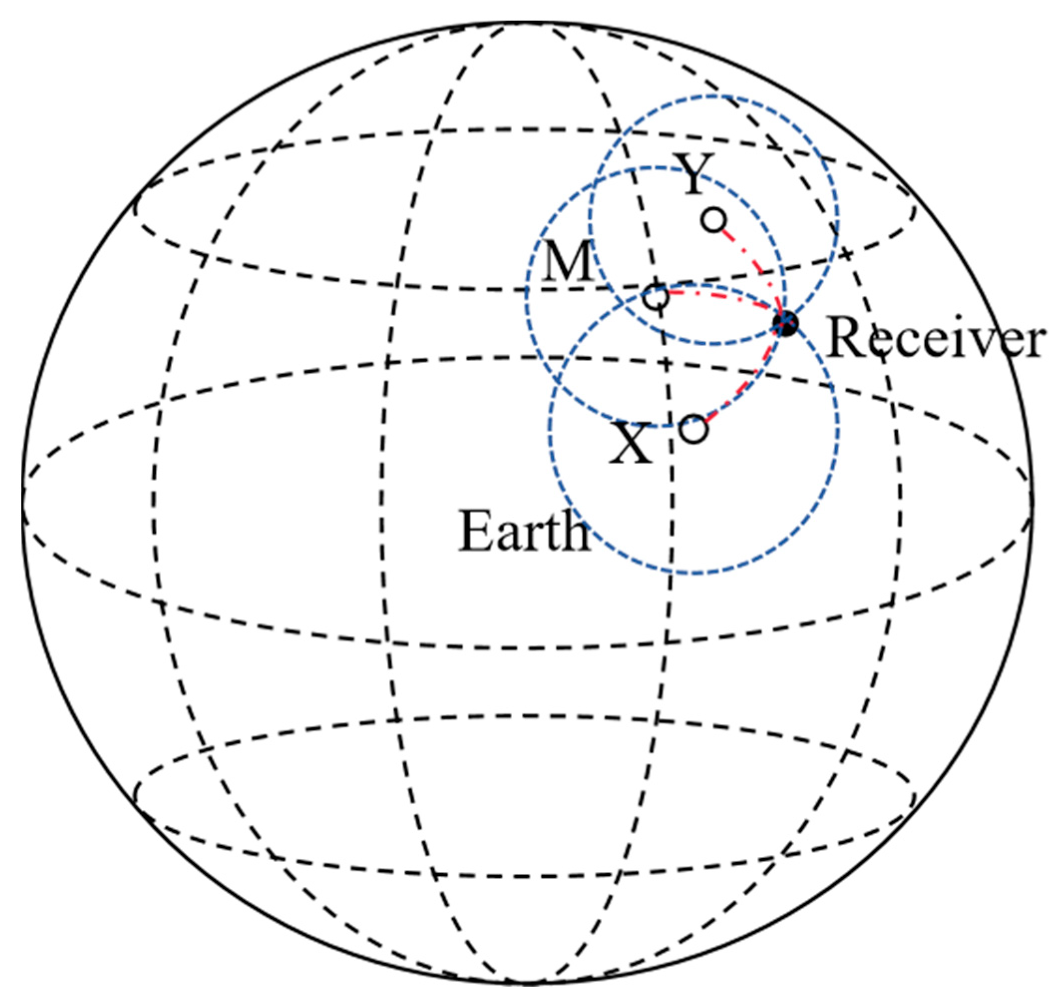
Figure 2 illustrates the principle of positioning using three Loran stations. Since there are three unknowns in the Loran pseudorange equations—φ, λ, and t—at least three equations are needed to form the equation set. This means that at least three stations are required. Unlike the GNSS satellite positioning equations, the long-wave signals transmitted by Loran stations propagate along the Earth’s surface. Therefore, the signal propagation path is not a straight line but an arc, as shown by the red dashed lines in Figure 2. Each Loran station serves as the center of a circle, with the distance from the station to the receiver as the radius, drawing circles on the Earth’s surface. The intersection point of the surfaces of the three circles represents the position of the receiver.
Since the pseudorange equation has three unknowns, φ, λ, and t, at least three equations are required to form a system of equations.
ρ 1 = L ( φ 1 , λ 1 , φ , λ ) + t 1 × c + δ 1 ρ 2 = L ( φ 2 , λ 2 , φ , λ ) + t 2 × c + δ 2 ρ 3 = L ( φ 3 , λ 3 , φ , λ ) + t 3 × c + δ 3

3. Loran-C Pseudorange Partial Differential Equations

Expand the system of equations at the initial values (φ0, λ0) and t0, using a first-order Taylor expansion to obtain the partial differential equations:
D 1 ρ 10 ( φ 0 , λ 0 , t u 0 ) ρ 1 φ | ρ 10 Δ φ + ρ 1 λ | ρ 10 Δ λ + ρ 1 t | ρ 10 Δ t D 2 ρ 20 ( φ 0 , λ 0 , t u 0 ) ρ 2 φ | ρ 20 Δ φ + ρ 2 λ | ρ 20 Δ λ + ρ 2 t | ρ 20 Δ t D 3 ρ 30 ( φ 0 , λ 0 , t u 0 ) ρ 3 φ | ρ 30 Δ φ + ρ 3 λ | ρ 30 Δ λ + ρ 3 t | ρ 30 Δ t
In the equation, Di is the true distance, which is the measured value with the error term removed. Express the system of equations in matrix form:
B = A X
B = D 1 ρ 1 D 2 ρ 2 D 3 ρ 3 , A = ρ 1 φ ρ 1 λ ρ 1 t ρ 2 φ ρ 2 λ ρ 2 t ρ 3 φ ρ 3 λ ρ 3 t , X = Δ φ Δ λ Δ t
ρ φ = A φ ( σ Δ σ ) + A ( σ φ Δ σ φ )
ρ λ = A λ ( σ Δ σ ) + A ( σ λ Δ σ λ )
Next, we will calculate each partial derivative term.
To calculate the partial derivatives of σ with respect to φ and λ, let u = sinσ and v = cosσ.
σ λ = 1 1 + ( u / v ) 2 λ u v
λ u v = v u λ u v λ v 2
u λ = cos 2 φ sin λ ' cos λ ' + cos φ i sin φ sin φ i cos φ sin λ ' sin 2 φ i cos 2 φ cos λ ' sin λ ' u
v λ = cos φ i cos φ sin λ '
u φ = sin 2 λ ' cos φ sin φ + cos 2 φ i sin φ cos φ cos φ i sin φ i cos λ ' ( cos 2 φ sin 2 φ ) sin 2 φ i cos 2 λ ' cos φ sin φ u
v φ = sin φ i cos φ cos φ i sin φ cos λ '
Calculate the partial derivatives of A and B with respect to φ and λ:
A φ = A d d φ
A λ = A d d λ
B φ = B d d φ
B λ = B d d λ
A d = 1 16384 4096 1536 d + 960 d 2 525 d 3
B d = 1 1024 256 256 d + 222 d 2 141 d 3
d φ = a 2 b 2 b 2 cos 2 φ i sin 2 λ ' 2 u sin φ cos φ + 2 cos 2 φ u φ u 3
d λ = a 2 b 2 b 2 cos 2 φ i cos 2 φ 2 u sin λ ' cos λ ' 2 sin 2 λ ' u λ u 3
Calculate the partial derivatives of Δσ with respect to φ and λ:
Let
s = B 4 ( v ( 1 + 2 cos 2 σ m 2 ) B 6 cos 2 σ m ( 3 + 4 u 2 ) ( 3 + 4 cos 2 σ m 2 ) )
Δ σ φ = B φ u ( cos 2 σ m + s ) + B u φ ( cos 2 σ m + s ) + B u ( cos 2 σ m φ + s φ )
Δ σ λ = B λ u ( cos 2 σ m + s ) + u λ B ( cos 2 σ m + s ) + B u ( cos 2 σ m λ + s λ )
cos 2 σ m φ = v φ 1 ( u 2 cos 2 φ i cos 2 φ sin 2 λ ' ) 2 [ 2 sin φ i ( u 2 cos φ + 2 u u φ sin φ ) ( u 2 cos 2 φ i cos 2 φ sin 2 λ ' ) 2 u 2 sin φ i sin φ ( 2 u u φ + 2 cos 2 φ i sin 2 λ ' sin φ cos φ ) ]
cos 2 σ m λ = v λ 1 ( u 2 cos 2 φ i cos 2 φ sin 2 λ ) 2 [ 4 u u λ sin φ i sin φ ( u 2 cos 2 φ i cos 2 φ sin 2 λ ) 2 u 2 sin φ i sin φ ( 2 u u λ 2 cos 2 φ i cos 2 φ sin λ cos λ ) ]
s φ = 1 4 B φ ( v ( 1 + 2 cos 2 σ m 2 ) B 6 cos 2 σ m ( 3 + 4 u 2 ) ( 3 + 4 cos 2 σ m 2 ) ) + B 4 ( v φ ( 1 + 2 cos 2 σ m 2 ) + 4 v cos 2 σ m cos 2 σ m φ 1 6 B φ cos 2 σ m ( 3 + 4 u 2 ) × ( 3 + 4 cos 2 σ m 2 ) B 6 cos 2 σ m φ ( 3 + 4 u 2 ) ( 3 + 4 cos 2 σ m 2 ) B 6 cos 2 σ m ( 8 u u φ ) × ( 3 + 4 cos 2 σ m 2 ) B 6 cos 2 σ m ( 3 + 4 u 2 ) × ( 8 cos 2 σ m cos 2 σ m φ ) )
s λ = 1 4 B λ ( v ( 1 + 2 cos 2 σ m 2 ) B 6 cos 2 σ m ( 3 + 4 u 2 ) ( 3 + 4 cos 2 σ m 2 ) ) + B 4 ( v λ ( 1 + 2 cos 2 σ m 2 ) + 4 v cos 2 σ m cos 2 σ m λ 1 6 B λ cos 2 σ m ( 3 + 4 u 2 ) × ( 3 + 4 cos 2 σ m 2 ) B 6 cos 2 σ m λ ( 3 + 4 u 2 ) ( 3 + 4 cos 2 σ m 2 ) B 6 cos 2 σ m ( 8 u u λ ) × ( 3 + 4 cos 2 σ m 2 ) B 6 cos 2 σ m ( 3 + 4 u 2 ) × ( 8 cos 2 σ m cos 2 σ m λ ) )
Substitute Equations (24)–(47) into Equation (23) and solve for the receiver’s position and time through iterative calculation. It is important to note that in pseudorange positioning and timing solutions, initial values need to be provided, and the choice of initial values is crucial. Inappropriate initial values can lead to non-convergence of the iteration, making the solution unattainable. Suitable ranges for initial value selection will be provided later in the text.
It can be seen that the Vincenty formula and partial differential equations use many trigonometric functions, which makes the pseudorange equations ill conditioned. In contrast, the GNSS positioning equations avoid using trigonometric functions. This is why the initial values for the GNSS pseudorange equations can be selected arbitrarily, while the Loran pseudorange equations have stricter initial value restrictions.
Having obtained the positioning equations and differential equations for both BDS and Loran-C, the BDS/Loran-C integrated positioning equations can be written as follows:
ρ 1 = ( x 1 x r ) 2 + ( y 1 y r ) 2 + ( z 1 z r ) 2 + c Δ t 1 + ε 1 ρ 2 = ( x 2 x r ) 2 + ( y 2 y r ) 2 + ( z 2 z r ) 2 + c Δ t 2 + ε 2 ρ 3 = ( x 3 x r ) 2 + ( y 3 y r ) 2 + ( z 3 z r ) 2 + c Δ t 3 + ε 3 ρ 4 = L ( φ 4 , λ 4 , φ , λ ) + Δ t 4 × c + ε 4
where ρ1, ρ2, ρ3 are the pseudoranges measured by the receiver to the satellites, and ρ4 is the pseudorange for Loran-C. (xi, yi, zi) represents the positions of the BDS satellites and the Loran-C transmission station; Δt represents the clock offset; c is the speed of light; and ϵ represents other errors.
By differentiating the system of equations, the position and timing information of the receiver can be obtained.

4. Results and Discussion

To verify the effectiveness of the pseudorange positioning and timing algorithm, it is essential to analyze the accuracy of positioning and timing, convergence speed, and the usable range of the algorithm. Therefore, this section will present the simulation analyses of the aforementioned metrics, considering two scenarios: with and without observation errors in pseudorange measurements.
In the scenario without observation errors, pseudorange observations directly represent the geodesic distance on the ellipsoidal surface. The errors in positioning and timing then represent the errors of the algorithm itself. In the scenario with observation errors, pseudorange observations typically deviate from the geodesic distance on the ellipsoidal surface, and the errors in positioning and timing reflect the impact of these observation errors.

4.1. No Observation Errors

This study selects a reference station in Eastern China for measurement, consisting of a main station (M) and two auxiliary stations (X, Y). In positioning measurements, the Geometric Dilution of Precision (GDOP) evaluates the impact of the geometric layout on positioning accuracy [23], encompassing Position Dilution of Precision (PDOP), Horizontal Dilution of Precision (HDOP), Vertical Dilution of Precision (VDOP), and Time Dilution of Precision (TDOP) [24].
GDOP is a comprehensive metric reflecting the impact of measurement geometry on position error. For the Loran-C system, good station distribution results in a low GDOP value and higher positioning accuracy, while poor geometry leads to a high GDOP value and greater positioning error. HDOP measures the geometric dilution factor for horizontal position errors (longitude and latitude), with a good horizontal distribution yielding a low HDOP value and higher accuracy. TDOP measures the geometric dilution factor for time measurement errors, where a low TDOP value indicates minimal impact on positioning accuracy, and a high TDOP value signifies a significant impact.
Optimizing the geometric distribution of stations in the Loran-C system can reduce GDOP, HDOP, and TDOP values, thereby improving positioning accuracy. These metrics are crucial indicators of the positioning accuracy of the Loran-C system, closely related to the system’s geometric layout and time synchronization. A lower GDOP value indicates a more ideal geometric distribution of observation points, resulting in more accurate positioning. Conversely, a high GDOP value indicates poor distribution, leading to increased positioning errors. Measuring the GDOP value helps select optimal measurement times and locations, identify and control measurement error sources, and improve positioning accuracy and reliability.
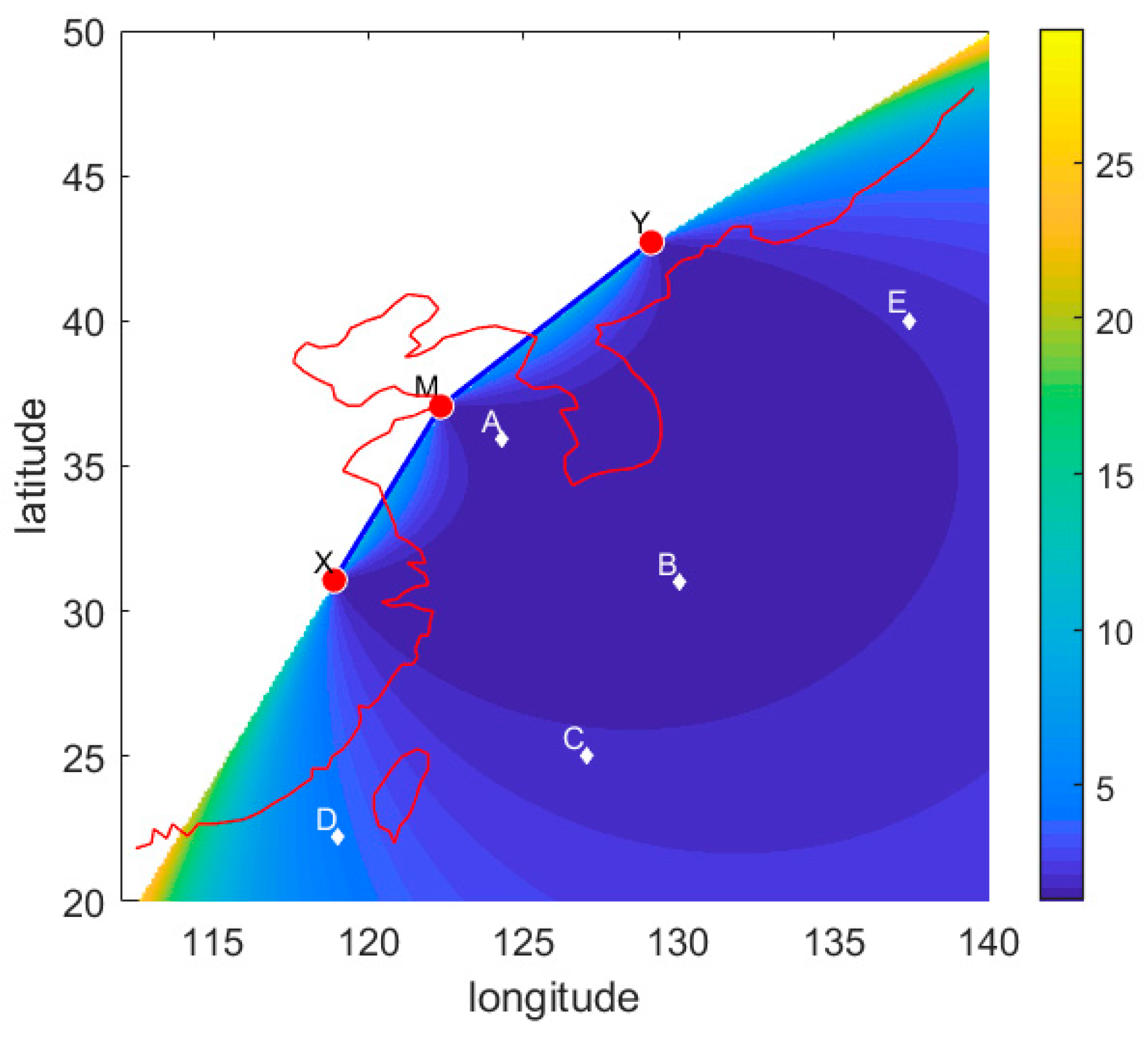
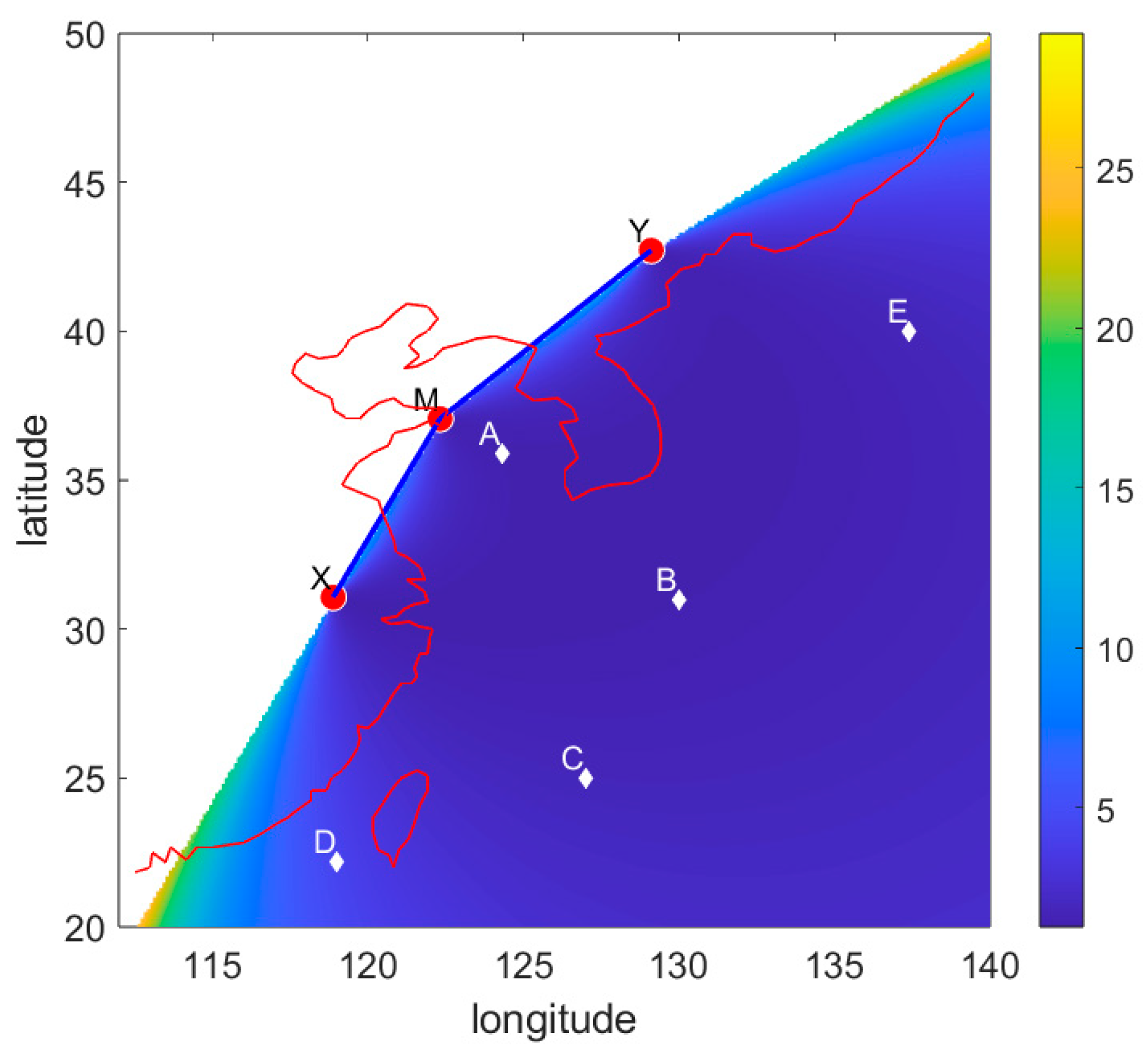
Figure 3 and Figure 4 depict the GDOP and HDOP, respectively, in the eastern waters of China, the distribution of the Loran station chain, and five selected measurement points for experimentation. Among the five points, Point A (35.9°, 124.3°) is the closest to the reference station, Point B (31°, 130°) has the lowest GDOP value, Points C (25°, 127°) and E (40°, 137.4°) have higher GDOP values and are roughly symmetrical, while Point D (22.2°, 119°) has the highest GDOP value. For the pseudorange algorithm, the selection of the initial value is crucial. Therefore, this study first needs to test the available range of initial values for the five test points. We selected the test range as longitude 110°E to 150°E, latitude 20°N to 50°N. With a unit interval of 0.1°, we tested the algorithm’s performance when the initial values are the chosen points. Assuming there are no observational errors means that the arrival time received by the receiver is the exact propagation time of the signal between two points, with no other error terms. The investigation examines the horizontal errors, timing errors, and iteration counts for each test point when selecting different initial pseudoranges.
Figure 5 shows the horizontal errors of five test points in the range of 110°E~150°E, 10°N~50°N. The horizontal error is obtained by calculating the plane distance between the true coordinates (test points) and the coordinates derived from the Vincenty formula algorithm.
It can be seen that when the horizontal error is less than 4 m, the initial value range of point A is the smallest, and it is only available in the range of about 120°E~138°E, 28°N~40°N. The initial value ranges of the remaining four points are relatively large, but they are all located in areas with low GDOP and HDOP values. This shows that in areas with low GDOP and HDOP values (GDOP < 10, HDOP < 5), the closer the test point is to the station chain, the smaller the selectable initial value valid range.
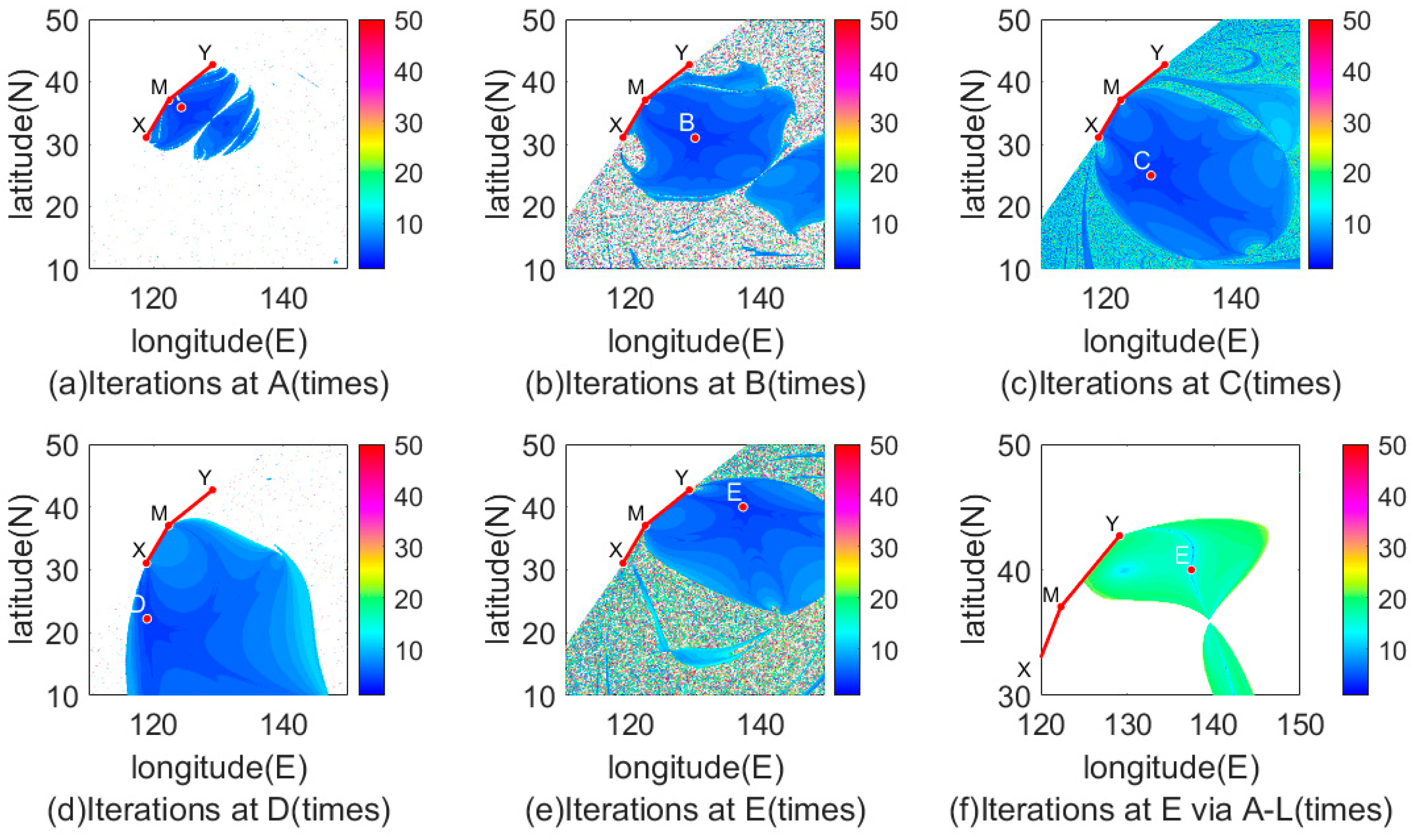
Within the initial value valid range, the horizontal errors of the five test points are all less than 4 m, the timing errors are less than 10−9 ns, and the number of iterations is less than 10 iterations. This is the error introduced by the algorithm itself. Lowering the iteration threshold of the algorithm can further improve the accuracy, but this means that more iterations are required. It can be seen that the algorithm not only has a wide range of initial value selection but also achieves fast and high-precision positioning and timing without pseudorange error.
From Figure 5e,f, it can be seen that when the horizontal error is less than 3 m, the initial value effective range of the Andoyer-Lambert pseudorange algorithm is smaller than that of the Vincenty pseudorange algorithm. The test results at point E show that the initial value range of the Vincenty pseudorange has increased by about four-times.
The Loran-C system’s transmission stations consist of one Master Station and several Secondary Stations. All transmission stations emit signals at strictly regulated time intervals, with the Master Station serving as the time reference. The Secondary Stations transmit their signals with a fixed time delay relative to the Master Station. The clocks of these stations are calibrated using highly precise atomic clocks to ensure accurate signal synchronization. The carrier frequency of the Loran-C signal (100 kHz) is precisely maintained in synchronization with UTC (Coordinated Universal Time). The receiver can use the phase information of the Loran-C signal to compare the received signal with the known UTC time signal, thereby obtaining the current accurate time. As radio waves propagate through the atmosphere, they are affected by various factors that introduce transmission errors. The receiver can correct these errors by receiving signals from multiple transmitters and calculating the timing errors, ensuring that the obtained time information is highly accurate.
Figure 6 shows the timing errors of the five test points. Similarly, within the effective range of the initial values, the timing errors of the five test points are less than 10−9 ns. This error is introduced by the algorithm itself. Timing errors of this order of magnitude can be ignored.
Figure 7 shows the number of iterations for the five test points. Within the effective range of the initial value, the threshold is set to 10−6 m, and the number of iterations for the five test points is less than 10-times.
From Figure 6e, it can also be seen that the number of iterations of the Andoyer-Lambert pseudorange algorithm is less than 30-times. Compared with the Vincenty pseudorange algorithm, the number of iterations has more than doubled.
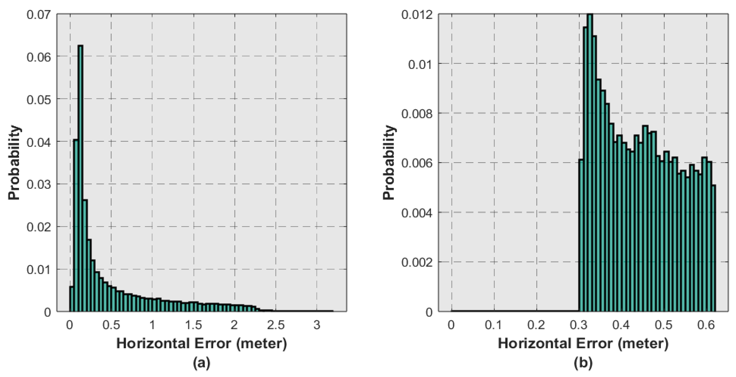
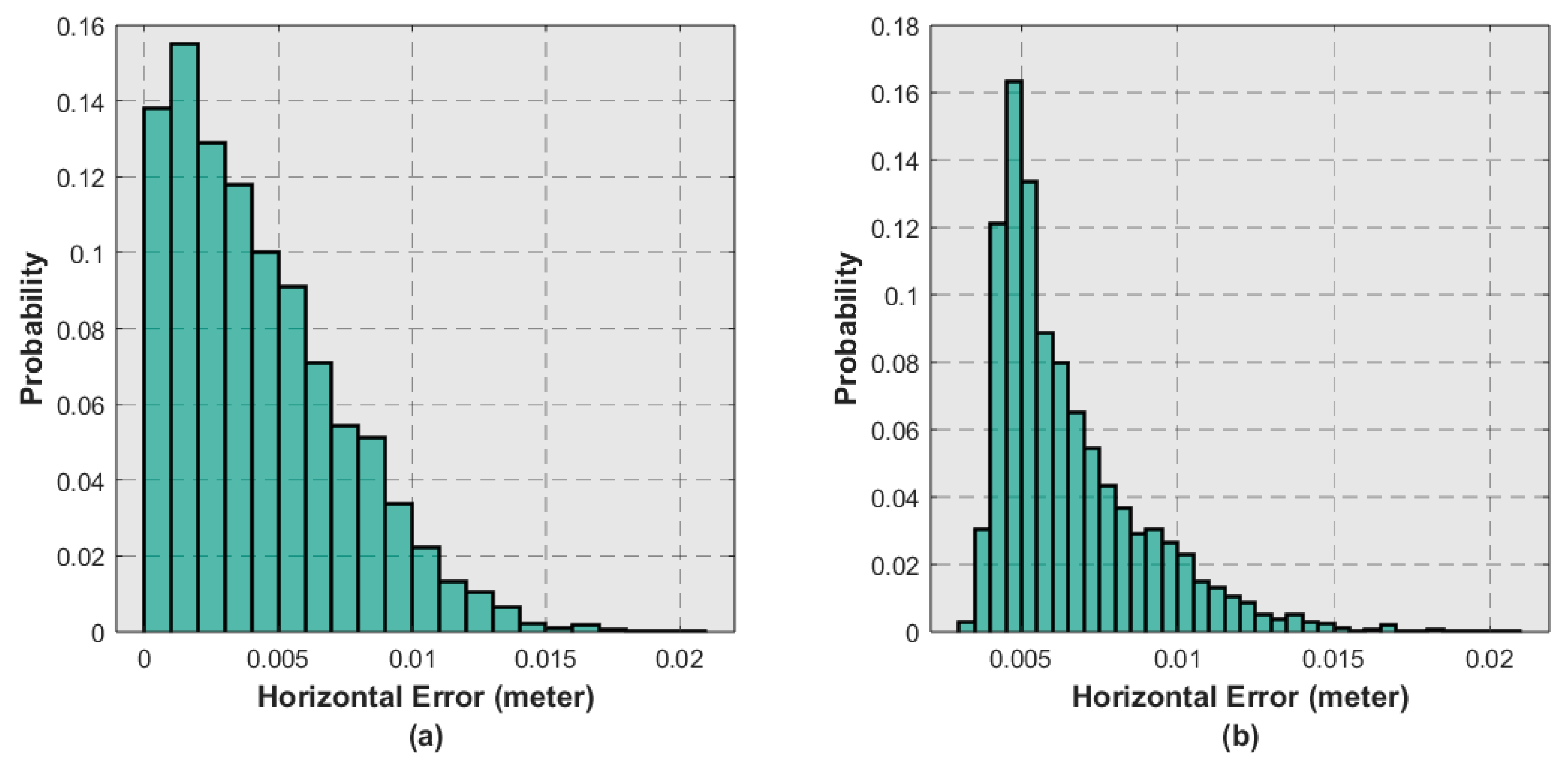
From the probability distribution diagram in Figure 8, it can be seen that the horizontal error values of the positioning results using the Vincenty formula for pseudorange calculation are superior to those using the Andoyer-Lambert formula for pseudorange calculation.

4.2. With Observation Errors

To further validate the positioning effectiveness of this method in real propagation paths, it is necessary to consider the related errors in pseudorange observations. Due to the propagation characteristics of long-wave signals, the signal will be subject to various environmental factors and disturbances during transmission. The main sources of errors include geographical positioning errors, propagation path errors, changes in atmospheric conditions, changes in terrain features, and refraction and reflection effects from the ionosphere and troposphere. These factors lead to uncertainty in signal propagation time, thereby affecting the accuracy of positioning. Additionally, the transmission of long-wave signals between ocean and land introduces differences in propagation speeds, increasing the complexity of errors. In long-wave transmission processes, factors affecting propagation errors are mainly described using PF (Primary Factor), SF (Secondary Factor), and ASF (Additional Secondary Factor) [25,26,27,28,29]. As correction methods for PF, SF, and ASF have been proposed, this study only considers the influence of random errors.
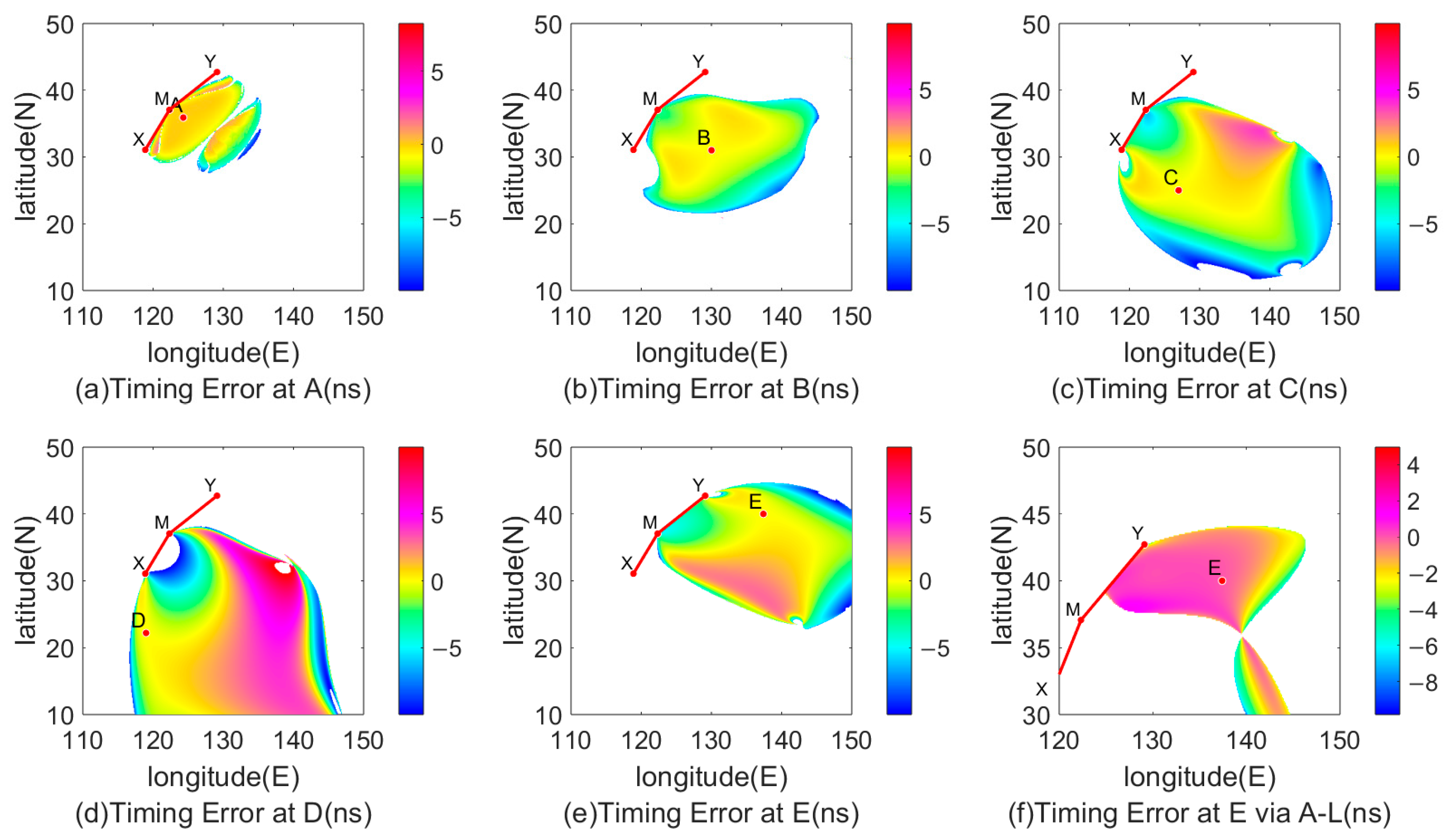
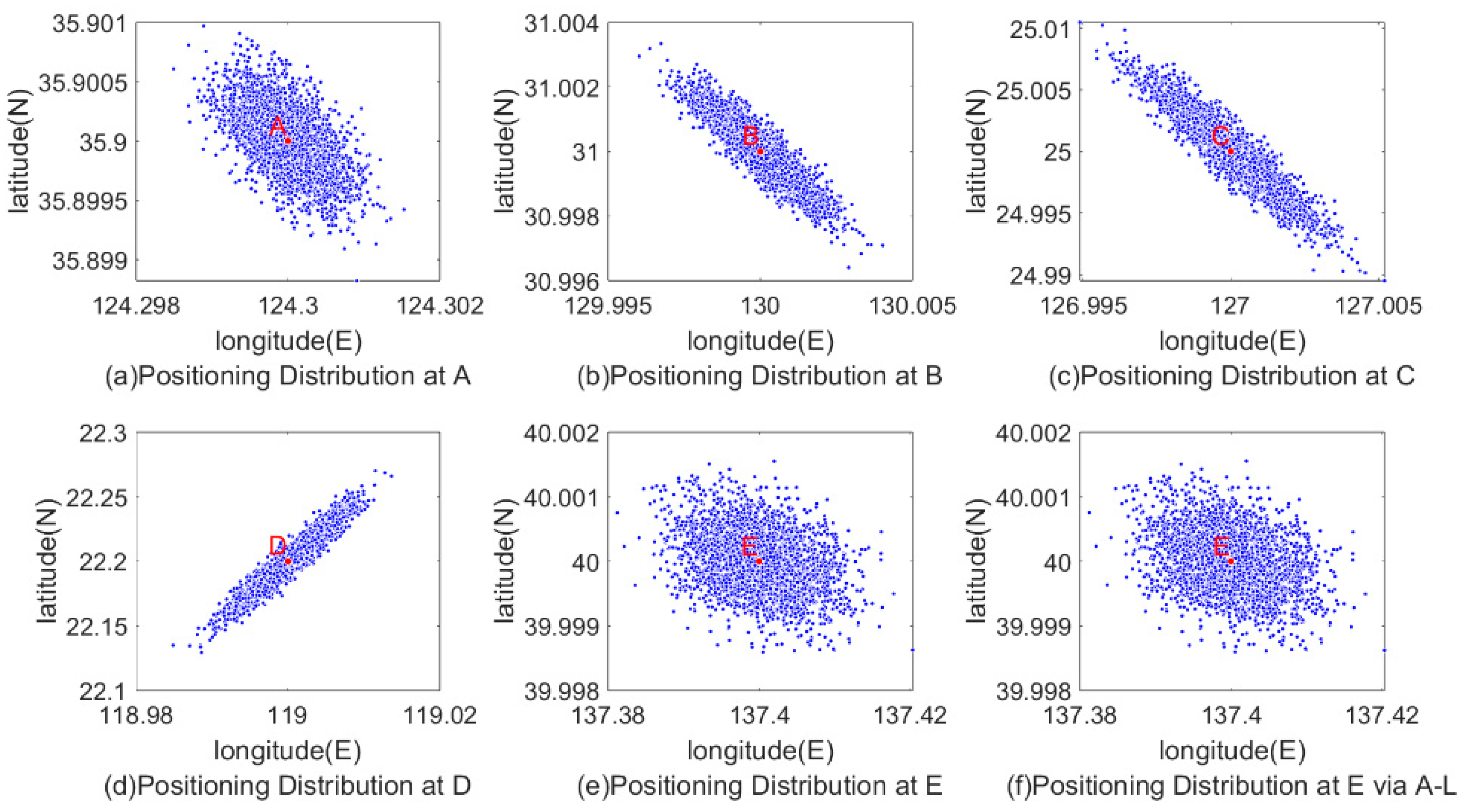
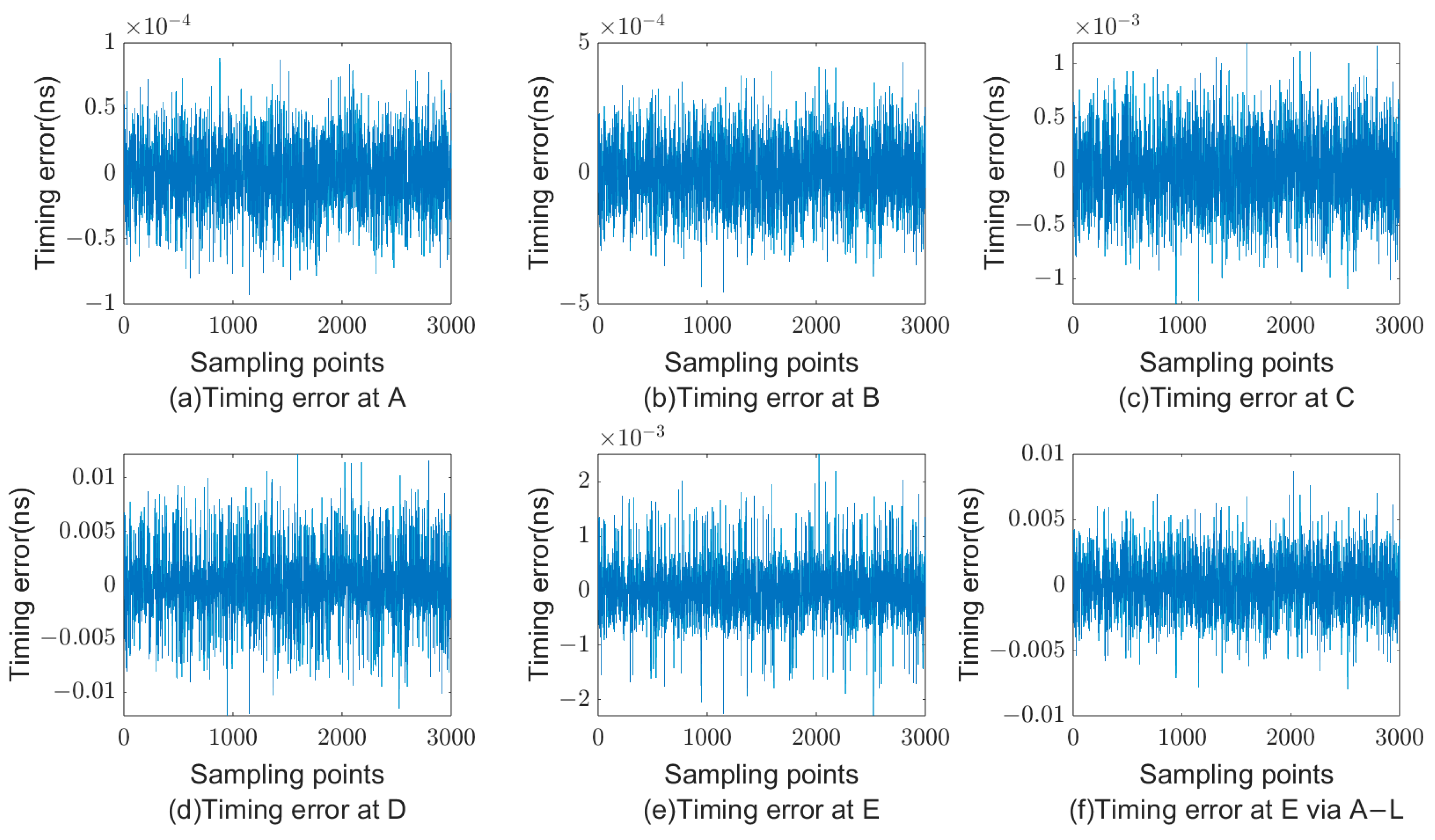
For the five test points, random noise with standard deviations of 10 ns, 50 ns, and 100 ns is, respectively, added, and 3000 samples are selected for analysis at each point. The positioning results, latitude errors, precision errors, and timing errors at point E are shown in Figure 8, Figure 9 and Figure 10. Additionally, the same random noise is added to Points A and B for comparison between the two pseudorange algorithms.
From Figure 9, Figure 10 and Figure 11 and the data in Table 1 and Table 2, it can be observed that the magnitude of random noise and the GDOP value both have an impact on positioning and timing errors. For the same test point, generally speaking, larger random noise leads to larger latitude, longitude, and timing errors. Taking Point A as an example, when adding 10 ns of random noise, the latitude error reaches −0.0145 m, the longitude error averages 0.0461 m, and the timing error averages −4.1967 × 10⁻⁸ ns. When increasing the random noise to 50 ns, these values increase to 0.0728 m, 0.2307 m, and −3.2213 × 10⁻⁷ ns, respectively. When the random noise increases to 100 ns, these values further increase to 0.1458 m, 0.4614 m, and −7.0156 × 10⁻⁷ ns, respectively. Similar situations occur for other test points. Analysis of the standard deviation yields similar conclusions.
Comparing the data of Points B, D, and E, it can be seen that when the GDOP value is large, adding the same noise at the test points leads to larger average errors and standard deviations. Moreover, the larger the GDOP, the larger the average error and standard deviation. Therefore, the positioning and timing errors of the receiver are also related to the GDOP value of the receiver’s position.
Comparison with the Andoyer-Lambert pseudorange method shows that at Points D and E, where normal measurements can be taken, the latitude error, longitude error, and their respective standard deviations of the Vincenty pseudorange method are similar to those of the former, while the timing error is lower than that of the former. This indicates that the positioning performance is comparable to the former, and the timing performance is superior. However, at Points A, B, and C, the Andoyer-Lambert Pseudorange method encounters singular values in measurements, making normal positioning and timing impossible. Thus, it can be seen that the Vincenty pseudorange method has a larger working range compared to the Andoyer-Lambert pseudorange method. From the probability distribution diagram, the horizontal error values of the positioning results using the Vincenty formula for pseudorange calculation are superior to those using the Andoyer-Lambert formula for pseudorange calculation.

4.3. Comparative Analysis

Appendix A presents the Andoyer-Lambert formula and the partial differential equations for pseudorange calculation based on this formula. The Andoyer-Lambert formula is a method for measuring geodesic distance. It is based on the ellipsoidal model, considering the Earth’s flattening and the geometric characteristics of the rotating ellipsoid. This formula achieves a balance between accuracy and computational efficiency. The accuracy of the Andoyer-Lambert formula is not high, mainly because it makes some approximations and simplifications when calculating the geodesic distance between two points on the Earth’s surface. These approximations and simplifications lead to reduced accuracy in certain situations, especially for longer distances or significant latitude differences. The specific reasons include the following:
  • Simplification of the ellipsoidal model: The Andoyer-Lambert formula is based on the rotating ellipsoid model of the Earth, but it uses approximate values such as the mean curvature radius and mean latitude during calculations. This approach ignores the complexity of the ellipsoid surface, resulting in cumulative errors.
  • Neglect of higher-order terms: The formula neglects some higher-order terms, leading to significant computational errors in cases of longer distances or larger geographic variations. These higher-order terms are crucial when considering subtle changes on the Earth’s surface.
Due to these reasons, the Andoyer-Lambert formula has limited accuracy in practical applications. In cases where high-precision geodesic distance calculations are required, more complex and precise formulas, such as the Vincenty formula, are typically used. The Vincenty formula accounts for more geometric characteristics and higher-order terms of the ellipsoid, thus providing higher accuracy in geodesic distance calculations.
The complexity analysis of the algorithm is as follows:
  • The Andoyer-Lambert formula calculates the distance between two points on the Earth’s surface through a series of constant assignments and basic trigonometric and arithmetic operations. Firstly, the algorithm initializes some constant values, which have a time complexity of O(1). Next, it calculates the δ value, involving several trigonometric function calls and basic arithmetic operations, with a time complexity of O(1). Then, the algorithm computes the δs value, which includes multiple trigonometric function calls and arithmetic operations, all of which have a time complexity of O(1). Finally, the algorithm performs a simple addition operation to calculate ρA, with a time complexity of O(1). Therefore, the overall time complexity of the algorithm is O(1), indicating constant time complexity. This means that regardless of the size of the input, the algorithm’s running time remains constant.
  • The pseudorange calculation algorithm based on the Andoyer-Lambert formula solves a series of constant assignments, trigonometric calculations, and basic arithmetic operations. All these operations are completed in constant time; therefore, the overall time complexity of the algorithm is O(1), indicating constant time complexity. This means that regardless of the size of the input, the algorithm’s running time remains constant.
  • The Vincenty formula completes its calculations through constant initialization, a single subtraction operation, and a fixed number of iterations. Each iteration involves multiple operations with constant time complexity. The subsequent calculations also consist of fixed arithmetic operations. Therefore, the overall time complexity of the algorithm is O(1), indicating constant time complexity, as the number of iterations is a constant.
  • The pseudorange calculation algorithm based on the Vincenty formula completes its calculations through constant initialization, trigonometric calculations, and a series of fixed-number basic arithmetic operations. Each step has a time complexity of O(1). Therefore, the overall time complexity of the algorithm is O(1), indicating constant time complexity.
Therefore, the pseudorange calculation method presented in this study has an algorithmic complexity comparable to the pseudorange calculation method based on the Andoyer-Lambert formula. Software verification has shown that the iteration count for the calculation is superior to the latter, as demonstrated in Figure 7.

5. Conclusions

The Loran-C pseudorange algorithm, based on the Vincenty formula proposed in this study, can simultaneously provide positioning and timing results. Through simulation analysis of the impact of random errors on positioning and timing, the effectiveness of this method has been verified. Simulation results show that when there are no observation errors in the pseudorange, positioning errors can reach the millimeter level, and timing errors can reach the order of 10−4 ns. In other words, the pseudorange algorithm can provide accurate positioning and timing results, and the error of the algorithm itself can be ignored. When observation errors are present in the pseudorange, both positioning and timing errors exhibit significant variations, which are also related to the GDOP and HDOP factors of the receiver and the station chain. The positioning and timing errors are not obvious in regions with lower GDOP values but become more pronounced in regions with higher GDOP values. Compared with the Andoyer-Lambert pseudorange algorithm, the Vincenty pseudorange algorithm avoids many singularity issues, achieves comparable positioning accuracy, and improves timing accuracy. The initial value range increased by more than four-times, and the computation speed nearly doubled.
We now have a method that allows for integrated positioning and timing with Loran-C and BDS. In future work, we will further investigate how to specifically implement the integrated positioning and timing of Loran-C and BDS, starting from the theoretical equations of integration mentioned in Section 3.

Author Contributions

Conceptualization, J.L. and H.W.; methodology, J.L. and H.W.; soft-ware, J.L.; validation, J.L. and H.W.; formal analysis, J.L.; investigation, J.L. and H.W.; resources, H.W.; data curation, J.L.; writing—original draft preparation, J.L.; writing—review and editing, J.L. and H.W.; visualization, J.L.; supervision, H.W.; project administration, H.W.; funding acquisition, H.W. All authors have read and agreed to the published version of the manuscript.

Funding

This research was funded by the Youth Innovation Promotion Association CAS, grant number Y2023109.

Data Availability Statement

The supporting data for this study can be obtained upon request from the corresponding author. Due to privacy concerns involving the participants, these data are not publicly available.

Conflicts of Interest

The authors declare no conflicts of interest.

Appendix A. Pseudorange Calculation Formula Based on Andoyer-Lambert Formula

Assume the receiver location is (φ, λ), and the Loran-C positioning station location is (φi, λi). The Andoyer-Lambert formula and its pseudorange settlement method formula are as follows:
ρ A = a ( δ + δ s )
Among them, ρA represents the geodesic distance between two points, a represents the major semi-axis of the earth, δ represents the spherical center angle corresponding to the geodesic distance between the points, and δs represents the correction amount of the spherical center angle.
cos δ = sin φ i sin φ + cos φ i cos φ cos ( λ λ i )
δ s = f 4 [ sin δ δ 1 + cos δ ( sin φ + sin φ i ) 2 sin δ + δ 1 cos δ ( sin φ sin φ i ) 2 ]
f = (ab)/a is the oblateness of the ellipsoid, and a and b refer to semi-major and semi-minor axes, respectively, of the WGS-84 ellipsoid.
ρ A φ = a δ φ + a δ s φ
ρ A λ = a δ λ + a δ s λ
δ φ = cos φ i sin φ cos ( λ λ i ) sin φ i cos φ 1 sin φ i sin φ + cos φ i cos φ cos ( λ λ i ) 2
δ s φ = δ s δ δ φ + δ s φ
δ s δ = f 4 [ [ ( cos δ 1 ) ( 1 + cos δ ) + ( sin δ δ ) sin δ ] ( sin φ + sin φ i ) 2 ( 1 + cos δ ) 2 ] f 4 [ [ ( cos δ + 1 ) ( 1 cos δ ) ( sin δ + δ ) sin δ ] ( sin φ sin φ i ) 2 ( 1 cos δ ) 2 ]
δ s φ = f 4 [ ( sin δ δ ) [ 2 ( sin φ + sin φ i ) ] cos φ 1 + cos δ ] f 4 [ ( sin δ + δ ) [ 2 ( sin φ sin φ i ) ] cos φ 1 cos δ ]
δ λ = cos φ i cos φ sin ( λ λ i ) 1 sin φ i sin φ + cos φ i cos φ cos ( λ λ i ) 2
δ s λ = δ s δ δ λ + δ s λ

References

  1. Cai, H.; Meng, Y.; Geng, C.; Gao, W.; Zhang, T.; Li, G.; Shao, B.; Xin, J.; Lu, H.; Mao, Y.; et al. BDS-3 performance assessment: PNT, SBAS, PPP, SMC and SAR. Acta Geod. Cartogr. Sin. 2021, 50, 427–435. [Google Scholar]
  2. Han, K.; Won, J. GNSS Signal Design Trade-off between Data Bit Duration and Spreading Code Period for High Sensitivity in Signal Detection. J. Position. Navig. Timing 2017, 6, 87–94. [Google Scholar] [CrossRef]
  3. Son, P.W.; Rhee, J.H.; Seo, J. Novel Multichain-Based Loran Positioning Algorithm for Resilient Navigation. IEEE Trans. Aerosp. Electron. Syst. 2018, 54, 666–679. [Google Scholar] [CrossRef]
  4. Ren, X.; Yang, Y. Development of Comprehensive PNT and Resilient PNT. J. Geod. Geoinf. Sci. 2023, 6, 1–8. [Google Scholar]
  5. Grant, A.; Ward, N.; Williams, P.; Hargreaves, C.; Inst, N. Developing Resilient PNT for all mariners. In Proceedings of the 28th International Technical Meeting of the Satellite-Division-of-the-Institute-of-Navigation (ION GNSS+), Tampa, FL, USA, 14–18 September 2015; pp. 932–938. [Google Scholar]
  6. Offermans, G.W.A.; Helwig, A.W.S.; vanWilligen, D. Eurofix: Test results of a cost-effective DGNSS augmentation system. J. Navig. 1997, 50, 209–223. [Google Scholar] [CrossRef]
  7. Helfrick, A. Question: Alternate position, navigation, timing, apnt? Answer: Eloran. In Proceedings of the IEEE/AIAA 33rd Digital Avionics Systems Conference (DASC), Colorado Springs, CO, USA, 5–9 October 2014. [Google Scholar]
  8. Lo, S.C.; Peterson, B.B.; Enge, P.K. Loran data modulation: A primer. IEEE Aerosp. Electron. Syst. Mag. 2007, 22, 31–51. [Google Scholar] [CrossRef]
  9. Kjerstad, N. The role of LORAN-C in present and future navigation: From a Norwegian nautical perspective. J. Navig. 2002, 55, 185–195. [Google Scholar] [CrossRef]
  10. Decai, Z.U.; Yujing, B.; Haitao, W.U.; Jianfeng, S.U.; Yun, L.I. Digital algorithm realized with SOPC for cycle identification of LORAN-C. J. Harbin Inst. Technol. 2005, 37, 1644. [Google Scholar]
  11. Jiangning, X.U.; Kejing, C.A.O.; Guoheng, C.U.I. Wigner-Vill Transformation Analysis for Cycle Identification of Loran-C. J. Proj. Rocket. Missiles Guid. 2010, 30, 211–214. [Google Scholar]
  12. Peng, Z.; Xueping, C.; Yinbing, Z.H.U.; Dongliang, H.U. Error Analysis for Loran-C Direction Based on Magnetic Antenna. J. Proj. Rocket. Missiles Guid. 2009, 29, 203–204. [Google Scholar]
  13. Johnson, G.W.; Swaszek, P.F.; Hartnett, R.J.; Shalaev, R.; Wiggins, M. An evaluation of eLoran as a backup to GPS. In Proceedings of the IEEE Conference on Technologies for Homeland Security—Enhancing Critical Infrastructure Dependability, Woburn, MA, USA, 16–17 May 2007; pp. 95–100. [Google Scholar]
  14. Johnson, G.; Shalaev, R.; Hartnett, R.; Swaszek, P.; Narins, N. Can LORAN meet GPS backup requirements? IEEE Aerosp. Electron. Syst. Mag. 2005, 20, 3–12. [Google Scholar] [CrossRef]
  15. Chuku, P.N.; Olwal, T.O.; Djouani, K. Enhanced RLS in Smart Antennas for Long Range Communication Networks. In Proceedings of the 9th International Conference on Ambient Systems, Networks and Technologies (ANT)/8th International Conference on Sustainable Energy Information Technology (SEIT), Porto, Portugal, 8–11 May 2018; pp. 196–205. [Google Scholar]
  16. Lee, S.J.; Chansik, P. Verification of GPS Aided Error Compensation Method and Navigation Algorithm with Raw eLoran Measurements. J. Inst. Control Robot. Syst. 2011, 17, 941–946. [Google Scholar]
  17. Li, S.; Wang, Y.; Hua, Y.; Xu, Y. Research of Loran-C data demodulation and decoding technology. Chin. J. Sci. Instrum. 2012, 33, 1407–1413. [Google Scholar]
  18. Ding, C.; Chen, J.; Liu, R. A new differential loran navigation system. Gnss World China 2019, 44, 68–76. [Google Scholar]
  19. Min, S.; Wang, J.; Jiang, T.; Tian, Z. The calculation research of hyperbolic navigation position fixing based on double station chains loran c navigator. J. Electron. Inf. Technol. 2003, 25, 700–703. [Google Scholar]
  20. Yan, B.; Li, Y.; Guo, W.; Hua, Y. A solution method of positioning and timing based on pseudo distance assigning for Loran-C. J. Time Freq. 2020, 43, 130–142. [Google Scholar]
  21. Yan, B.R.; Li, Y.; Guo, W.; Hua, Y. High-Accuracy Positioning Based on Pseudo-Ranges: Integrated Difference and Performance Analysis of the Loran System. Sensors 2020, 20, 4436. [Google Scholar] [CrossRef]
  22. Sodano, E.M.; Robinson, T.A. Direct and Inverse Solutions of Geodesics; Army Map Service: Great Falls, VA, USA, 1963.
  23. Kaiser, S.A.; Christianson, A.J.; Narayanan, R.M. Global positioning system processing methods for GPS passive coherent location. IET Radar Sonar Navig. 2017, 11, 1406–1416. [Google Scholar] [CrossRef]
  24. Gilgien, M.; Spörri, J.; Limpach, P.; Geiger, A.; Müller, E. The Effect of Different Global Navigation Satellite System Methods on Positioning Accuracy in Elite Alpine Skiing. Sensors 2014, 14, 18433–18453. [Google Scholar] [CrossRef]
  25. Zhong, E.J.; Huang, T.Z. Geometric dilution of precision in navigation computation. In Proceedings of the 5th International Conference on Machine Learning and Cybernetics, Dalian, China, 13–16 August 2006; pp. 4116–4119. [Google Scholar]
  26. Hu, S.; Jingshu, Y.; Fangling, Z. The Minimum Value of GDOP in Pseudo-range Positioning. Fire Control Command 2009, 34, 22–24. [Google Scholar]
  27. Li, R.; Su, J.; Wang, N. ASF Correction in Long-wave Time Service. J. Astronaut. Metrol. Meas. 2011, 31, 34–36. [Google Scholar]
  28. Luo, N.; Mao, G.; Lachapelle, G.; Cannon, E. ASF Effect Analysis Using an Integrated GPS/eLORAN Positioning System. In Proceedings of the 2006 National Technical Meeting of the Institute-of-Navigation, Monterey, CA, USA, 18–20 January 2006; pp. 967–976. [Google Scholar]
  29. Chen, X.M.; Li, W.K.; Chen, Y.B.; Xu, J.N.; Chen, H.Q. Calculation & Research on ASF Correction of Loran-C. J. Astronaut. Metrol. Meas. 2009, 29, 26–30. [Google Scholar]
Figure 1. Principle of satellite navigation.
Remotesensing 16 03227 g001
Figure 2. Principle of Loran navigation, where M, X, Y is the location of Loran-C stations.
Remotesensing 16 03227 g002
Figure 3. GDOP in the East China Sea. M, X, Y is the location of Loran-C stations.
Remotesensing 16 03227 g003
Figure 4. HDOP in the East China Sea. M, X, Y is the location of Loran-C stations.
Remotesensing 16 03227 g004
Figure 5. Horizontal error for each point when there is no error. (a) Description of the error at A; (b) description of the error at B; (c) description of the error at C; (d) description of the error at D; (e) description of the error at E; (f) description of the error at E via Andoyer-Lambert pseudorange formula.
Remotesensing 16 03227 g005
Figure 6. Timing error for each point when there is no error. (a) Description of the error at A; (b) description of the error at B; (c) description of the error at C; (d) description of the error at D; (e) description of the error at E; (f) description of the error at E via Andoyer-Lambert pseudorange formula.
Remotesensing 16 03227 g006
Figure 7. Iterations for each point when there is no error. (a) Description of the iterations at A; (b) description of the iterations at B; (c) description of the iterations at C; (d) description of the iterations at D; (e) description of the iterations at E; (f) description of the iterations at E via Andoyer-Lambert pseudorange formula.
Remotesensing 16 03227 g007
Figure 8. Probability distribution of horizontal error at point E with no observation error. (a) Using the Vincenty method; (b) using the Andoyer-Lambert method.
Remotesensing 16 03227 g008
Figure 9. Distribution of positioning results when adding random errors with a standard deviation of 100 ns to each test point. (a) Description of the position distribution at A; (b) description of the position distribution at B; (c) description of the position distribution at C; (d) description of the position distribution at D; (e) description of the position distribution at E; (f) description of the position distribution at E via Andoyer-Lambert pseudorange formula.
Remotesensing 16 03227 g009
Figure 10. Timing error test results when adding random errors with a standard deviation of 100 ns to each test point. (a) Description of the timing error at A; (b) description of the timing error at B; (c) description of the timing error at C; (d) description of the timing error at D; (e) description of the timing error at E; (f) description of the timing error at E via Andoyer-Lambert pseudorange formula.
Remotesensing 16 03227 g010
Figure 11. Probability distribution of horizontal error at point E with observation error. (a) Using the Vincenty method; (b) using the Andoyer-Lambert method.
Remotesensing 16 03227 g011
Table 1. Effect of random noise on Vincenty pseudorange algorithm.
Test
Points
Standard Deviation of Random Noise (ns)Latitude Error (m)Longitude Error (m)Timing Error (ns)
Average ValueStandard DeviationAverage ValueStandard DeviationAverage ValueStandard Deviation
A100.01453.10080.04614.6460−4.1967 × 10−81.9600 × 10−6
500.072815.54720.230723.2354−3.2213 × 10−71.2980 × 10−5
1000.145831.09500.461446.4707−7.0156 × 10−72.6284 × 10−5
B10−0.016410.58390.101412.3326−1.1825 × 10−71.2607 × 10−5
50−0.078652.92800.504361.6634−6.0343 × 10−76.3636 × 10−5
100−0.1517105.85611.0034123.3268−1.2173 × 10−61.2729 × 10−4
C10−0.185133.67770.168315.8401−2.7780 × 10−73.5111 × 10−5
50−0.9090168.38900.836579.1997−1.3894 × 10−61.7565 × 10−4
100−1.7786336.77801.6616158.3992−2.7385 × 10−63.5131 × 10−4
D10−1.2042226.1134−0.017143.0685−1.3028 × 10−62.3630 × 10−4
50−5.32691.1306 × 1030.0632215.34531.3573 × 10−60.0012
100−8.91812.2612 × 1030.4982430.69963.4052 × 10−50.0031
E100.07675.15380.075659.4536−1.2754 × 10−74.4168 × 10−5
500.383825.77390.3421297.2689−4.3492 × 10−72.2153 × 10−4
1000.767851.54800.5946594.54471.0323 × 10−55.1741 × 10⁻⁴
Table 2. Effect of random noise on Andoyer-Lambert pseudorange algorithm.
Test
Points
Standard Deviation of Random Noise (ns)Latitude Error (m)Longitude Error (m)Timing Error (ns)
Average ValueStandard DeviationAverage ValueStandard DeviationAverage ValueStandard Deviation
A10Singular Singular Singular Singular Singular Singular
50Singular Singular Singular Singular Singular Singular
100Singular Singular Singular Singular Singular Singular
B10Singular SingularSingular SingularSingular Singular
50Singular SingularSingular SingularSingular Singular
100Singular SingularSingular SingularSingular Singular
C10Singular SingularSingular SingularSingular Singular
50Singular Singular Singular SingularSingular Singular
100Singular Singular Singular SingularSingular Singular
D10−1.2611224.7706−0.022342.9398−2.4705 × 10−64.9488 × 10−4
50−5.35241.1293 × 1030.0605215.22662.0029 × 10−50.0033
100−8.93732.2598 × 1030.4958430.5754−1.5791 × 10−50.0073
E100.08015.17670.089659.3417−3.7059 × 10−71.3543 × 10−4
500.389525.80020.3661297.0585−1.7350 × 10−69.2721 × 10−4
1000.761651.52920.5689594.7925−3.0196 × 10−60.0021
Disclaimer/Publisher’s Note: The statements, opinions and data contained in all publications are solely those of the individual author(s) and contributor(s) and not of MDPI and/or the editor(s). MDPI and/or the editor(s) disclaim responsibility for any injury to people or property resulting from any ideas, methods, instructions or products referred to in the content.