Article

Adaptive Channel Estimation Based on Multidirectional Structure in Delay-Doppler Domain for Underwater Acoustic OTFS System

1
Ocean Institute, Northwestern Polytechnical University, Taicang 215400, China
2
School of Marine Science and Technology, Northwestern Polytechnical University, Xi’an 710072, China
*
Author to whom correspondence should be addressed.
Remote Sens. 2024, 16(17), 3157; https://doi.org/10.3390/rs16173157
Submission received: 16 July 2024 / Revised: 22 August 2024 / Accepted: 25 August 2024 / Published: 27 August 2024

Abstract

:
Time-varying underwater acoustic (UWA) channels are the key challenge of underwater acoustic communication (UAC). Although UAC exhibits time-variance characteristics significantly in time domains, its delay-Doppler (DD) domain representation tends to be time-invariant. Orthogonal time–frequency space (OTFS) modulation has recently been proposed and has acquired widespread interest due to its excellent performance over time-varying channels. In the UWA OTFS system, the novel DD domain channel estimation algorithm that employs a multidirectional adaptive moving average scheme is proposed. Specifically, the proposed scheme is cascaded by a channel estimator and moving average filter. The channel estimator can be employed to estimate the time-invariant channel of the DD domain multidirectionally, improving proportionate normalized least mean squares (IPNLMS). Meanwhile, the moving average filter is used to reduce the output noise of the IPNLMS. The performance of the proposed method is verified by simulation experiments and real-world lake experiments. The results demonstrate that the proposed channel estimation method can outperform those of benchmark algorithms.

Graphical Abstract

1. Introduction

Achieving reliable and efficient communication has always been the core goal in underwater acoustic communications (UACs), which is the best method for medium-to-long-range communication underwater [1]. It is well known to be the most complicated wireless channel, and the characteristics of UWA channels include strong multipath, time variance, large time delays, and Doppler shifts. Despite some high-rate transmission schemes, including single-carrier frequency domain equalization [2,3,4] and orthogonal frequency division multiplexing (OFDM), having been proposed [5,6,7,8] recently, they still are unsuitable for underwater acoustic channels with characteristic of time–frequency double selective fading.
Orthogonal time frequency space (OTFS) modulation, which can convert the time-varying multipath channels into the delay-Doppler (DD) domain, in which the channels tend to be time-invariant, seems to be an optional technique to tackle the above problem [9,10]. Although OTFS shows merits in anti-time-varying channels [11,12,13] compared with that of OFDM, it may suffer severe inter-Doppler interference (IDI) and intersymbol interference (ISI) [11] when OTFS works in doubly dispersive channels. Thus, in this case, equalization definitely needs to be employed in the OTFS system [11,14]. Since prior channel information achieved by channel estimation is needed in most equalizers [15,16], channel estimation highly affects performance and plays a key role in the OTFS system.
There has been some research on channel estimation of OTFS systems. In [12], K. R. Murali et al. estimated the OTFS channel by using a PN pilot sequence, achieving lower channel estimation errors with longer pilot sequences. In [17,18], the impulse pilot was utilized for channel estimation in the DD domain. Its main idea is to insert a big value in the middle of the DD domain, and there are enough zero pilots as the guard pilots. Then, the channel parameters are filtered out at the receiver by setting an appropriate threshold. In [19], the pilot design is improved to reduce pilot overhead during in estimating channel of the MIMO system with the OTFS technique. In [20], a joint channel estimation and equalization method related to the OTFS system is proposed by using expectation propagation (JCEE- EP).
Utilizing the channel sparsity of the DD domain seems to be feasible to lighten the computation burden induced by long pilot [21]. For example, Shen W. proposed a 3D orthogonal matching pursuit algorithm (OMP) to efficiently estimate the downlink channel of the MIMO OTFS system. Since OMP has shown bad performance in bit error rate (BER) [22], and modified subspace pursuit (MSP) suffers from excessive computational burden [23], the two-choice hard thresholding pursuit (TCHTP) algorithm was proposed for the MIMO and MultiUser (MU) OTFS systems [23,24]. In [25], by designing a Dolph–Chebyshev window to enhance the sparsity of the channel, the estimation accuracy of the OTFS system channel was improved effectively. Some methods related to exploiting channel sparsity of the DD domain are discussed too. For example, the authors applied sparse Bayesian learning in channel estimation [26], while a novel scheme also proposed to estimate the channel in the UWA OTFS system for the purpose of avoiding the disadvantage caused by fractional Doppler [27].
Different from the above work focused on exploiting the channel sparsity of the DD domain, some previous work tends to estimate channel OTFS systems in the time domain, which was first proposed in [28]. Das S. S. et al. presented a time-domain equivalent channel matrix estimation method based on energy threshold and spline interpolation [29]. Meanwhile, exploiting the time–frequency (TF) domain sparsity of the channel seems to be feasible too [30]. In [31], Pfadler A. et al. proposed a channel estimation scheme that can effectively restrain the leakage on the OTFS system by exploiting smoothness regularization in TF space.
The compressed sensing (CS) method proposed by Donoho D.L. [32] was also employed to estimate the channel of the OTFS system recently. A CS estimation scheme for OTFS channels with sparse multipath was introduced in [33]. In [34], the author combined Fibonacci search and OMP together to estimate the channel with fractional delay and Doppler characteristics. Along with deep learning developing rapidly in recent years, scholars have also carried out some work to introduce deep learning into OTFS channel estimation field [35,36,37,38,39]. Hu J. et al. combined the time-domain method and deep learning method together in [40], with low complexity and good flexibility.
Nonetheless, it is worth acknowledging that the methods mentioned earlier can mostly be seen as block-wise channel estimation methods. Thus, the performance of these methods may deteriorate severely in low signal–noise ratio scenes. We introduce a symbol-based adaptive method that estimates the channel of the OTFS system in the DD domain by improving proportionate normalized least mean squares (IPNLMS) [41]. Generally speaking, the symbol-based channel estimation method could generate an estimated channel in each adaptation step, which is usually used to estimate and track the time-varying channels [42]. In the DD domain in the OTFS system, the channels could be seen as invariant after phase compensation during one OTFS symbol. Then, these estimation results generated by multiple adaptation steps can be regarded as multiple noisy samples related to the same channel. Noticing this characteristic, we propose a new denoise strategy scheme which is composed of three processes to enhance the accuracy of adaptive channel estimation. The superiority of the proposed method is finally verified by simulation and lake experiment.

2. System Model

2.1. OTFS Modulation

Two-dimensional base functions with properties including nonlocal TF domain and local DD domain are used in OTFS modulation. These functions map the symbol information onto a grid in the DD domain, where the M × N transmitted signals occupy time duration, N T , and bandwidth, B = Δ f M , in which T and Δ f = 1 T describe the OTFS block duration and the subcarrier spacing, respectively. The information symbols x l , k , l = 0 , , M 1 , k = 0 , , N 1 are discretized into a grid in the DD domain, Γ = { ( l M Δ f , k N T ) , for l = 0 , , M 1 , k = 0 , , N 1 } , where 1 M Δ f and 1 N T represent the resolutions of delay and the resolutions of Doppler axes, respectively.
Figure 1 shows the UAC system diagram, mainly including two modules, namely, the transmitter for modulation and the receiver for demodulation. Transmitter maps x l , k into samples X m , n in the TF domain through inverse symplectic finite Fourier transform (ISFFT), as shown in Figure 1.
By employing the Heisenberg transform, one can convert the TF domain signals X m , n to time domain signal S .
S = G t x F M H X
where F is the fast Fourier transform (FFT) matrix, G t x = diag [ g t x ( 0 ) , g t x ( T / M ) , ⋯, g t x ( ( M 1 ) T / M ) ] , g t x ( t ) is the transmit pulse-shaping waveform. In this paper, a rectangular waveform is employed to shape the Heisenberg transform, leading to inverse finite Fourier transform (IFFT), which will greatly reduce the computational complexity. In order to mitigate ISI, we obtain the time-domain signal after adding a cyclic prefix (CP), then
S = A C P S
where A C P C ( M + N CP ) × N represents a CP addition matrix, and N CP represents the length of added CP. To be transmitted by the antenna, vectorization operation changes the paralleled data matrices S to data vector S , which is listed as follows:
s = vec { S }
According to [10], the time-varying channels in the DD domain can be sparsely represented as  
h ( τ , ν ) = i = 1 P h i δ ( τ τ i ) δ ( ν ν i )
where P is the total number of delay taps; h i , τ i and ν i , respectively, represent the propagation gain, delay, and Doppler shift associated with the i-th path, for i = 1 , , P . In the same DD grid as the OTFS signals, τ i and ν i are defined by the following:
τ i = l τ i M Δ f , ν i = k τ i N T ,
As can be seen in Equation (5), given large enough M and N, the delay l τ i and Doppler shifts k τ i may nearly be integers.
At the receiver, we denote the time domain signal of the OTFS system through underwater acoustic channels as r. The received vector form of the time-domain signal is first parallelized into a matrix,
R = invec { r }
Then, by removing the CP, the obtained matrix can be written as
R = R CP R
where R C P C M × ( M + N CP ) represents the CP-removing matrix.
Similarly with transmitting, the received signal Y in the DD domain can be converted in the TF domain by using a Wigner transformer. Since the received pulse is a rectangular pulse waveform, the Wigner transform degenerates into the discrete Fourier transform. Then, applying SFFT, Y tends to be a 2D periodic convolution of X DD . The element of Y is given by
Y l , k = l = 0 M 1 k = 0 N 1 X l , k H [ l l ] M , [ k k ] N e ϕ ( α , β ) + V l , k
where H l , k represents the channel matrix in the DD domain, and V l , k denote the channel and additive white Gaussian noise in the DD domain. [ ( · ) ] M represents ( · ) mod M, and [ ( · ) ] N represents ( · ) mod N. As a compensated phase, ϕ ( α , β ) can be written as follows:
ϕ ( α , β ) = j 2 π β ( ( M 1 ) + α ) ( M + N CP ) N , β N 2 j 2 π ( β N ) ( ( M 1 ) + α ) ( M + N CP ) N , β > N 2
where α = [ l l ] M , β = [ k k ] N .
Channels H l , k in the DD domain can be obtained by using channels h q , l in the time domain, leading to
H l , k = i = 1 N h ( i 1 ) ( M + N CP ) + 1 , [ l ] M e j 2 π ( i 1 ) k N
Denoting the maximum delay as τ m a x and the maximum Doppler as ν m a x , the maximum delay and Doppler of the grid in the DD domain can be written as L = τ m a x M Δ f and K = ν m a x N T , respectively. Therefore, the counts of the nonzero elements in H C M × N can be calculated as L × ( 2 K + 1 ) .

2.2. Adaptive Channel Estimation

For convenience of presentation, we introduce an intermediate quantity  
U l , k = X [ l l ] M , [ k k ] N e φ ( l l , k k )
where φ ( l l , k k ) can be listed as
φ ( l l , k k ) = j 2 π ( k k + N 2 ) ( ( M 1 ) + ( l l ) ) ( M + N CP ) N , ( k k ) N 2 j 2 π ( k k ) ( ( M 1 ) + ( l l ) ) ( M + N CP ) N , ( k k ) < N 2
Thus, the Equation (8) can be rewritten as
Y l , k = l = 0 M 1 k = 0 N 1 H l , k X [ l l ] M , [ k k ] N e φ ( l l , k k ) + V l , k = l = 0 M 1 k = 0 N 1 H l , k U l , k + V l , k
To note this, the training signal X l , k and compensated phase e φ ( l l , k k ) are both known for the receiver.
For convenience, we transform Equation (13) into a one-dimensional vector form, which can be described as follows:
Y l , k = Λ H u + v
where Λ = vec { H * } , u = vec { U } , v = vec { V } .
Let H ^ l , k denote the estimated channel. Then, the error between the received signal and the system output based on the estimated channel can be written as follows:
E l , k = Y l , k l = 0 M 1 k = 0 N 1 H ^ l , k U l , k = Y l , k Λ ^ H u
Since the channels in the DD domain are sparse, the cost function is given by
J l , k = E l , k 2 2 + 2 γ Λ ^ 1
where the operation · 1 and · 2 denote the l 1 norm and l 2 norm, respectively. In Equation (16), an l 1 norm penalty is introduced, which could improve the convergence and accuracy of the adaptive algorithm by exploiting the sparsity of the channel.
We adopt the IPNLMS algorithm to estimate the parameters. The update equation is given by
( Λ ^ ) = Λ ^ + μ ( E l , k ) * G u H G u + δ u
where ( Λ ^ ) is the updated parameters, μ is the step, G denotes a diagonal proportionate matrix with p-th diagonal element
G p , p = 1 α 2 L h + ( 1 + α ) | Λ ^ | 2 | | Λ ^ | | 1 + ϵ
δ and ϵ are small positive numbers, called regularizers. L h is the size of Λ ^ , and | · | is the absolute value operation. 1 α < 1 determines the filter sparsity.
Compared with the normalized least mean square (NLMS) algorithm, the updating Equation (17) of the IPNLMS algorithm has very fast convergence and tracking when the mpulse response path is sparse. By using an average coefficient, the updating Equation (17) even performs better than the proportionate normalized least mean square (PNLMS) algorithm when the impulse response is dispersive. If α = 1 , this algorithm reduces to the NLMS, and if α = 1 , the algorithm performs more like the PNLMS.
If Equation (17) converges, the estimated channel is given by
H ^ = invec { ( Λ ^ ) * }
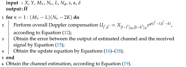
The pseudocode of Adaptive channel estimation based on the IPNLMS algorithm is presented as follows in Algorithm 1:
Algorithm 1: Pseudo codes of Adaptive channel estimation based on IPNLMS
Remotesensing 16 03157 i001

3. The Proposed Channel Estimation Methods

In this section, three denoise methods are proposed to enhance the accuracy of adaptive channel estimation by supposing the channel in the DD domain is nearly constant.

3.1. Denoising Method 1

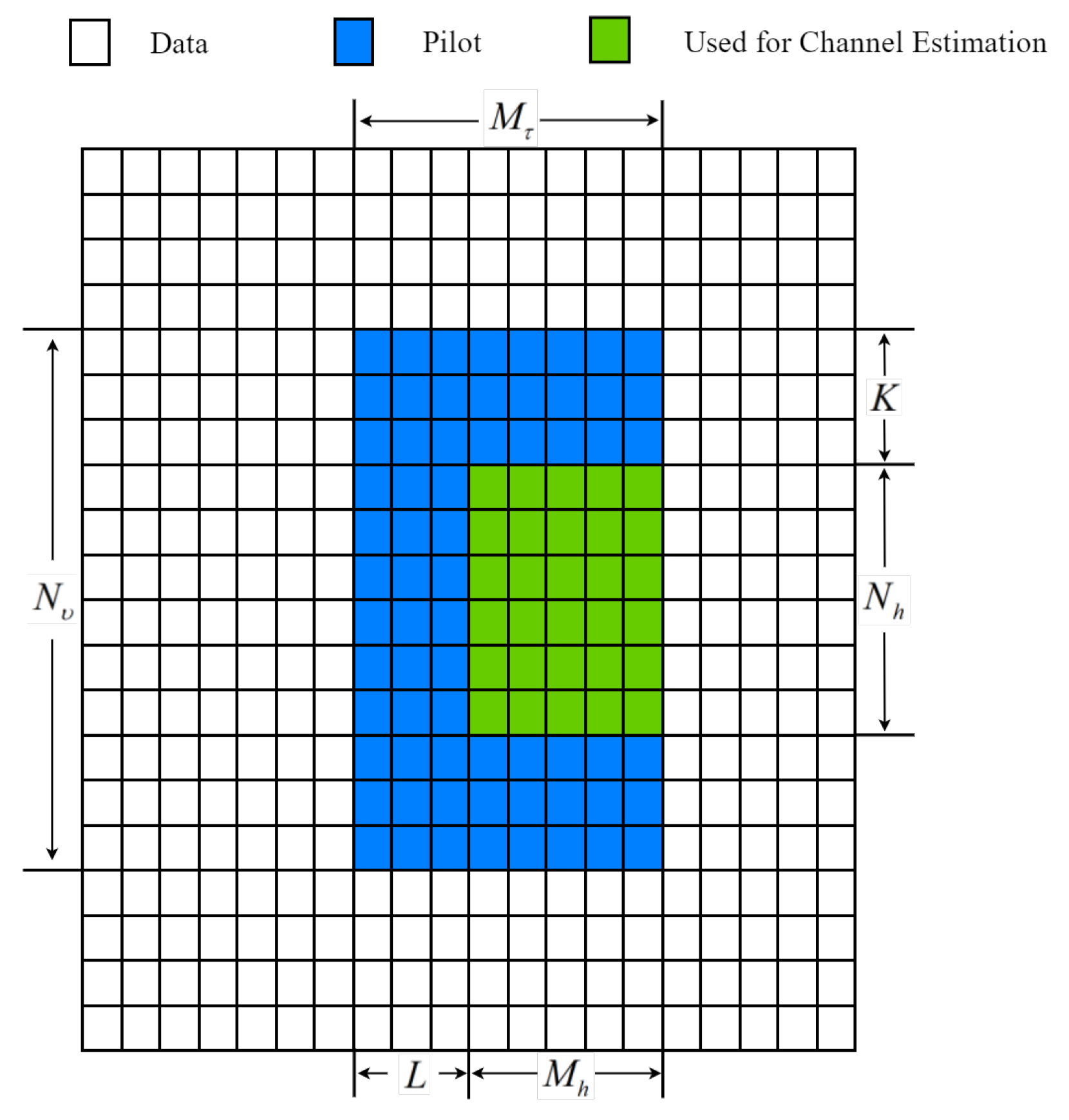
Since a channel estimator outputs one by one once it achieves convergence, the filter could generate multiple estimated samples. Observing the received pilot symbols in the DD domain, which are described in Figure 2, we can find that N total = ( M τ L ) ( N ν 2 K ) symbols can be used for channel estimation. By supposing the estimator is converged after N c steps, it can output N h = N total N c effective samples.
Due to it only choosing one from multiple samples to represent the channel, the traditional adaptive channel estimation method may deteriorate the estimation accuracy due to the impact of estimation noise, while in the proposed method, we define the N h samples as the multiple observations associated with the same channel. Thus, the i-th estimated sample can be described as the sum of the channel’s true value and the estimated error.
H ^ i = H + e i , i = 1 , , N h
Similar to Jing’s work, estimated error e i can be modeled as random noise. Based on the invariant characteristic of random noise, we develop two simple yet efficient denoising strategies to enhance the performance of the proposed method. The first one is to combine the N h samples by the arithmetic average operation. Then, the final estimated channel of the filter is given by
H ˜ = 1 N h i = 1 N h H ^ i
= H + 1 N h i = 1 N h e i
Assume the noise e i is independent, and the variance is σ e 2 . Thus, the variance of the estimated error is reduced to 1 N h σ e 2 . It is noted that the noise variance is proportional to 1 N h . As the value of N h increases, the change in the variance becomes smaller and smaller. When N h is large enough, the effect of increasing the number of N h is very small.

3.2. Denoising Method 2

Moving average (MA) is one of the most commonly used denoising methods in digital signal processing, capable of reducing white noise while maintaining the stability of step response to some extent. The working principle of the moving average filter is to take the average of multiple points in the input sequence as the corresponding point in the output sequence, expressed as
y ( n ) = 1 D i = 0 D 1 x ( n i )
where x ( n ) , y ( n ) are the input and output sequences, respectively, and D represents the moving average step length. Adding an MA filter after the IPNLMS algorithm convergence, the updating Equation (17) can be expressed as
Λ ^ ( n ) = 1 D i = 0 D 1 ( Λ ^ ( n i ) )
Furthermore, to enhance the convergence efficiency of the moving average, we also consider the exponential moving average (EMA) filter when denoising. When computing EMA, the weight in the window tends to exponentially decrease with the length of the filter. The input–output relation of EMA filter is given by
y ( n ) = i = 0 D 1 γ i x ( n i ) i = 0 D 1 γ i
where γ is called the weight factor, usually a value close to 1. It is clear that γ is a parameter to control the real-time performance of the moving average, since it shows a positive relation with past cumulative value and a negative relation with the current sampler. Adding an EMA filter after the IPNLMS algorithm convergence, the updating Equation (17) can be expressed as
Λ ^ ( n ) = i = 0 D 1 γ i ( Λ ^ ( n i ) ) i = 0 D 1 γ i

3.3. Denoising Method 3

For the traditional 1D adaptive channel equalization system, the adaptive algorithm can be operated both in the forward and backward directions along with the received data, which is called bidirectional adaptive equalization. It exploits the time diversity to improve the performance. The basic principle of this technique is that the parameters to be estimated in the two directions are the same.
Inspired by the idea of bi-directional adaptive equalization, we also developed a multidirectional adaptive algorithm for OTFS channel estimation. According to the 2D structure of received data in the DD domain, as shown in Figure 2, there are multiple directions to scan the received data Y . First of all, the data scanning strategy can be preliminarily divided into column scanning or row scanning. Then, for the column-wise strategy, it can scan from the left column to the right column or from the right to the left. For the row-wise strategy, it can scan from the bottom row to the top row or from the top to bottom. Thus, for each symbol in Figure 2, there are 4 directions to complete the scan. If we only consider starting from the corner of the matrix, at least 8 directions can be generated.
The filter can obtain an output for each direction. And the estimated performance of each filter is similar since they are the same except for the flow of the input symbols. Then, we also adopt an arithmetic average operation to combine the multiple estimated results. Let H ˜ ( j ) , j [ 1 , , N d ] denote the estimated channel in the different directions. Thus, the final estimated channel of the proposed method is given by
H ˇ = 1 N d j = 1 N d H ˜ ( j )
The developed multidirectional adaptive algorithm exploits the diversity to improve performance. According to the Equation (27), the multidirectional technology is also a kind of denoising processing.
According to the three denoising methods proposed in this section, the IPNLMS-MA-MuD algorithm is given in Algorithm 2. The key steps of the proposed multidirectional moving average filtering algorithm based on the moving average filter are to calculate the channel matrix estimation values in four directions according to the steps of IPNLMS. In each direction of adaptive channel estimation, a moving average filter is added. Specifically, the estimation value of the IPNLMS algorithm at that step is calculated first, followed by the average of the results from the previous D1 iterations, and then, this average value instead of the output of the current iteration is to be the input of the next iteration. The remaining steps are similar to the previously mentioned multidirectional adaptive channel estimation scheme.
Algorithm 2: Pseudocodes of IPNLMS-MA-MuD
Remotesensing 16 03157 i002

3.4. Computation Complexity Analysis

Since the proposed method is symbol-wise adaptive, the complexity of each iteration is described in Equation (17), which namely shows linear growth with the length of pilot symbols.
Since decision feedback equalization (DFE) based on proposed channel estimations is a symbol level equalizer, we can deduce that its complexity experiences linear growth with the symbols in one OTFS frame. Meanwhile, the equalization computation burden of each symbol is linearly increasing with the size of filters; thus, the computation burden of the proposed DFE can be written as O ( M N ( Q L w + L u ) ) . The computation burden order of the single-channel matching pursuit-based (MP-based) method is described as O ( n iter M N S L Θ ) , in which n iter , S L , and Θ denote the number of iterations, the number of nonzero channel taps, and the alphabet size, respectively. Thus, we can conclude that the computation burden of the MP-based method is mainly determined by the sparsity level of channels. The computation burden induced by channel estimation also should be considered of course. We can deduce that the proposed 2D DFE receiver achieves the lowest complexity with large M and N compared with traditional methods.

4. Simulation and Lake Experiment Results

4.1. Results of Simulations

In this section, the performance of the proposed channel estimation methods in the OTFS system is verified by simulations. It should be noted that all simulations and experiments are run on the MATLAB 2022 platform. Complex-value UWA channels are simulated according to [43]. The system parameters of the UWAc system are set as Table 1.
According to the characteristics of the channel, we consider an OTFS system with the parameters shown in Table 2. The parameters explained in the previous section of the proposed algorithm are set in Table 3.
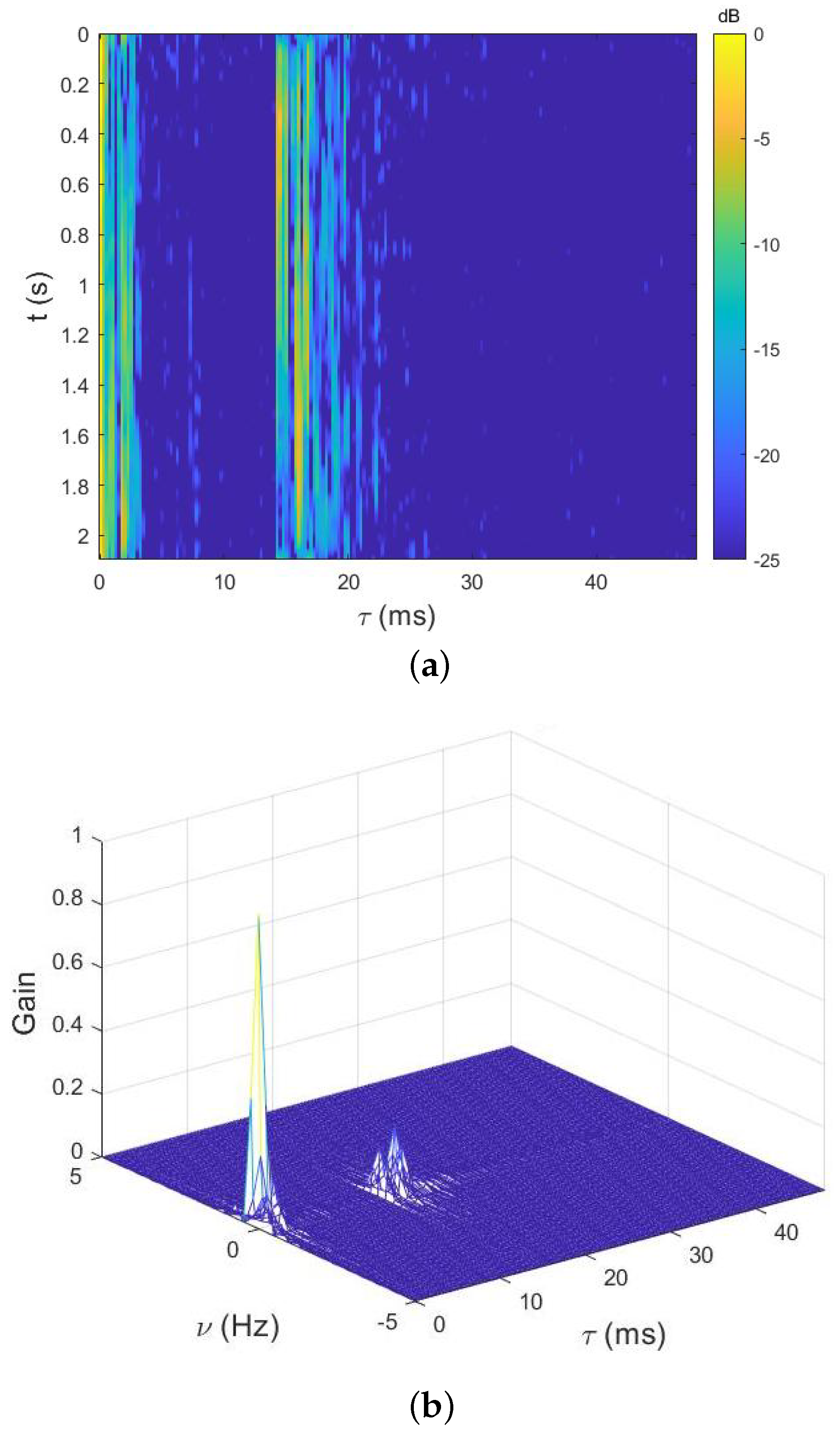
Figure 3 describes the channel structure in the time domain (Figure 3a) and the scattering function of the UWA channel (Figure 3b). It is clear that at least nine clusters of multipath with obvious time variance are shown in Figure 3a. The Doppler offset of each path in the channel in the DD domain is plotted in Figure 3b. We can find that it tends to be different with taps. Moreover, the maximum range of the Doppler spread is near [ 0.7 , 0.7 ] in the first cluster of this channel.
In Figure 4, we give the estimation accuracy comparison of three different single-direction adaptive algorithms. IPNLMS represents that no denoising method is used in the estimate. IPNLMS-TA represents that the estimate of each filter is denoised by averaging the N h estimates. From Figure 4, we find that the effect of the denoising processing is positive, especially in low-noise ratio (SNR) situations. The performance gain is about 0.02 dB for the denoising method 1. Therefore, we adopt denoising method 1 in all of the following simulations.
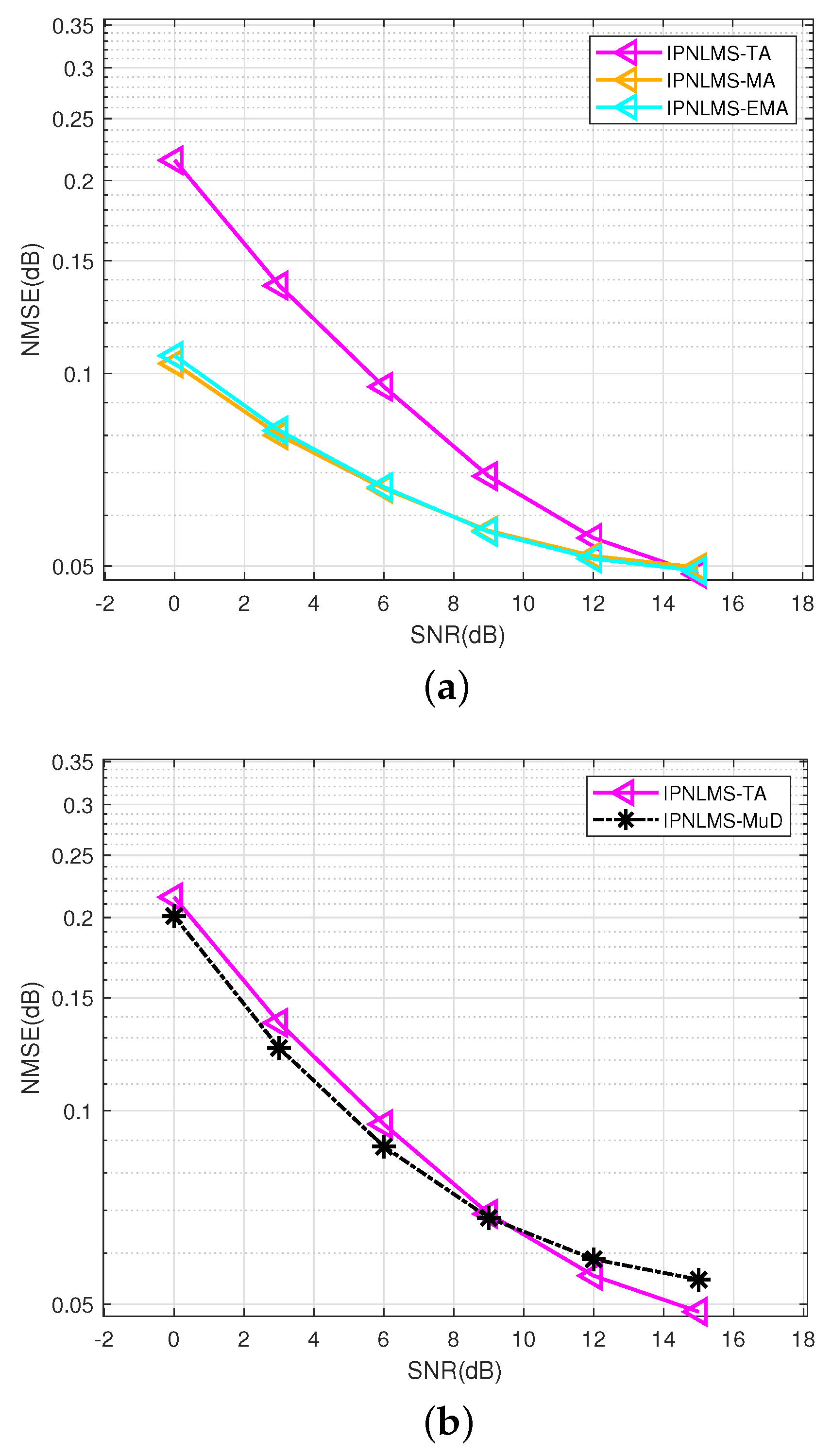
Figure 5 plots an estimation accuracy versus SNR of various adaptive algorithms. To clarify the impact of denoising method 2 on single-directional IPNLMS, we first compare the normalized mean square error (NMSE) among several methods, as shown in Figure 5a. IPNLMS-single represents that the estimate of each filter is denoised by denoising method 1, only averaging the N h estimates. IPNLMS-MA-single and IPNLMS-EMA-single represent the adaptive channel estimation technique that includes an MA or EMA filter with a step size of 5 in the IPNLMS-single basis, respectively. The performance improvement of adding an MA or EMA filter to IPNLMS-single is evident from the graph, both ranging from 0 to 0.1 dB. By comparing IPNLMS-MA-single and IPNLMS-EMA-single, there is little difference in performance between the two MA filters.
After establishing that the MA filter can be employed to enhance the accuracy of the adaptive channel estimation algorithm, we compare the multidirectional moving average IPNLMS-TA method with the adaptive channel estimation technique algorithm, in which the MA filter is unemployed in Figure 5b. IPNLMS-MuD represents the performance of the multidirectional IPNLMS-TA algorithm. The comparison between the IPNLMS-MuD and IPNLMS-TA curves shows a performance improvement in multidirectional over single-direction channel estimation. It should be noted that when the SNRs are higher than 9 dB, denoising method 3 no longer has its advantages. However, considering the characteristic of low SNR in the marine environments, denoising method 2 is still valuable in the UWA field.
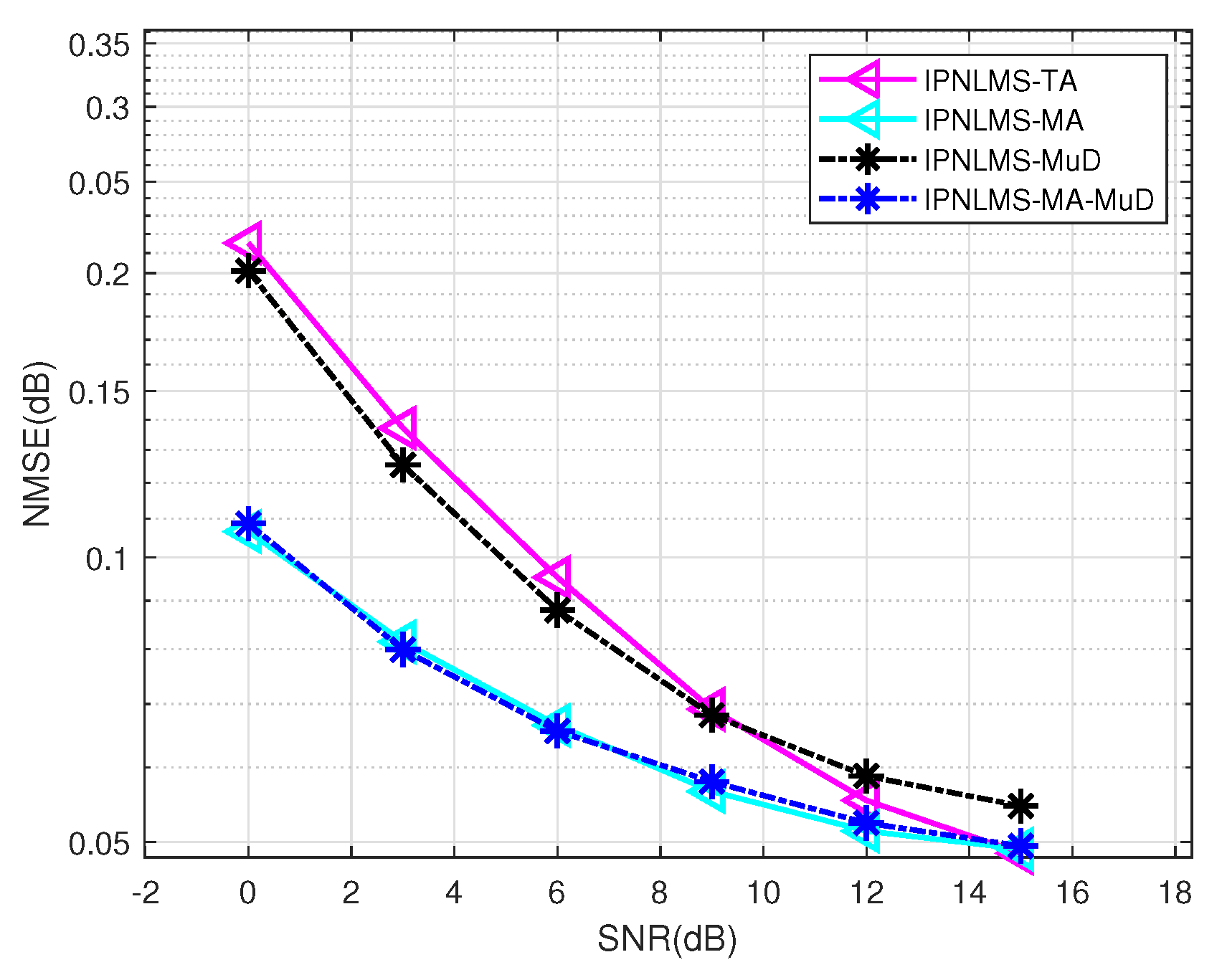
Earlier in this section, we verified that all three denoising methods can be used to enhance the estimation accuracy of adaptive channel estimation algorithms in UWA channels. To choose the method with the best estimation accuracy, we combine three denoising methods and compare their performance with other methods mentioned above, as shown in Figure 6. The IPNLMS-MA-MuD means, on the basis of IPNLMS-MuD, an MA filter is added in each direction of the adaptive channel estimation. Through the comparison, we can find that IPNLMS-MA-MuD performs best in these four adaptive channel estimation algorithms, especially in low SNR conditions, which conform to the characteristics of the marine environment. In conclusion, the simulation experiments we conducted above preliminarily demonstrate the improved estimation accuracy of the proposed method over previous methods.

4.2. Results of Lake Experiment

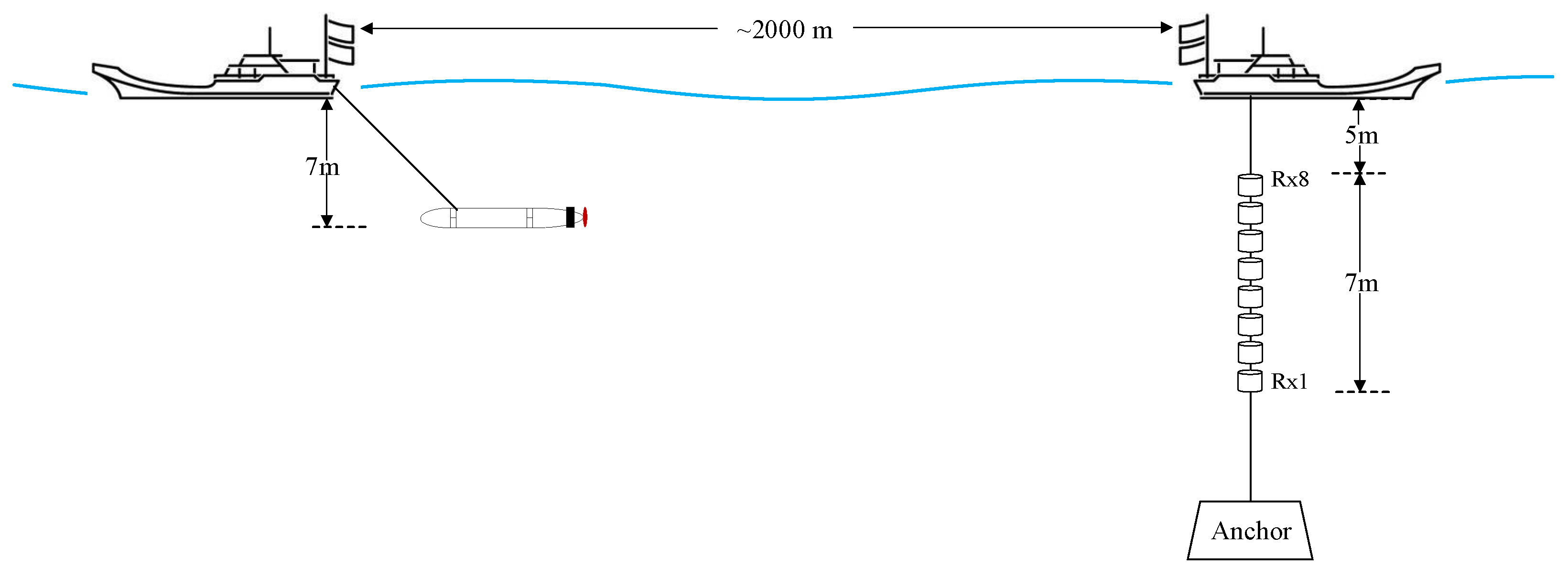
To further verify the effectiveness of the proposed IPNLMS-MA-MuD method, we conducted a single-input single-output (SISO) UAC experiment in real underwater acoustic communication scenarios. This field experiment was part of the main objective to drive the UWA channel equalizer’s channel estimation. The UAC experiment was conducted in July 2022 at the Danjiangkou Reservoir in Hubei Province; the experiment scene is shown in Figure 7. The experimental site had an average depth of 50 m. The transmitter transducer was located at about 23 m underwater in a static state and at a depth of about 3 to 7 m when moving. The receiver used an eight-element array with a 1-meter spacing between elements, and the top hydrophone was 5 m below the surface. The communication distance between the transmitting and receiving boats ranged from 300 to 1500 m, with the receiving boat remaining stationary and the transmitting boat moving at a speed of 2 to 4 knots. The receiving hydrophone had a sampling frequency of 48 kHz. Each set of data obtained from the experiment contained 16 groups of OTFS symbols.
In this section, we used a channel-estimator-based equalizer to recover the transmitted signal. As the physical underwater acoustic channel impulse responses (UWA CIRs) were still unknown in the field experiment, this method allowed for a quantitative assessment of communication quality, i.e., the accuracy of the estimated UWA CIRs was reflected through the quality of communication.
Given experimental field data, Table 4 describes the communication quality of several different adaptive channel estimation methods. In Table 4, the B E R = e / n , namely the ratio of the number of received erroneous bits e to the total number of transmitted bits n, was chosen as the metric for communication quality. It is clear that lower BER indicates better communication performance. It was found that the proposed IPNLMS-MA-MuD method achieves the best performance in all cases. In addition, the average bit error rate of the proposed IPNLMS-MA-MuD method is 0.46%, while the average bit error rate of the IPNLMS method is 1.34%. It is clear that the average bit error rate of the proposed IPNLMS-MA-MuD method reduces by about 0.88% compared with the IPNLMS methods. Using the IPNLMS-MA-MuD algorithm, the time-delay and delay-Doppler underwater acoustic channel estimation obtained by processing field data are in Figure 8.

5. Conclusions

In this paper, we present a symbol-based adaptive channel estimation method in the DD domain for the OTFS system. It incorporates multidirectional scanning and noise reduction techniques by using an MA filter. The simulation results and field experimental data processing together demonstrate that the proposed channel estimation method is superior to the traditional pulse-based channel estimation method and the traditional IPNLMS method in terms of estimation accuracy. Specifically, in the simulation, the MMSE between the estimated channel matrix and the true channel matrix is reduced compared with that of traditional methods. Moreover, the channel data that were sampled in the Danjiangkou Lake experiment are employed to verify the performance of the proposed method. The results show that the BER of the proposed method is lower than that of the traditional method.

Author Contributions

Conceptualization, W.S., M.J., L.J. and C.H.; methodology, W.S., M.J. and L.J.; software, W.S., M.J., L.J. and N.T.; validation, W.S., M.J. and L.J.; investigation, W.S., M.J. and L.J.; material, W.S. and L.J.; data supervision, W.S., M.J. and L.J.; writing—preparation of original draft, M.J. and L.J.; writing—review, editing, and polishing, W.S., M.J. and L.J.; visualization, M.J., L.J. and N.T.; supervision, W.S., L.J. and C.H.; project administration, W.S., L.J. and C.H.; funding acquisition, W.S. and L.J. All authors have read and agreed to the published version of the manuscript.

Funding

This research was funded by the National Natural Science Foundation of China (NSFC) under Grant No. 62371393 and 62471397, the Stable Supporting Fund of Acoustic Science and Technology Laboratory under Grant No. TCKYS2024604SST3010, and the Fundamental Research Funds for the Central Universities (23GH02027).

Data Availability Statement

The original contributions presented in the study are included in the article, further inquiries can be directed to the corresponding author.

Acknowledgments

The authors would like to thank anyone who supported the review of this paper.

Conflicts of Interest

The authors declare no conflicts of interest.

Abbreviations

The following abbreviations are used in this manuscript:
UWAtime-varying underwater acoustic
UACunderwater acoustic communication
DDdelay-Doppler
OTFSorthogonal time frequency space
IPNLMSimproving proportionate normalized least mean squares
OFDMorthogonal frequency division multiplexing
IDIinter-Doppler interference
OMPorthogonal matching pursuit
BERbit error rate
MSPmodified subspace pursuit
TCHTPtwo-choice hard thresholding pursuit
MUMulti-User
TFtime–frequency
CScompressed sensing
ISFFTinverse symplectic finite Fourier transform
FFTfast Fourier transform
IFFTinverse finite Fourier transform
CPcyclic prefix
NLMSnormalized least mean square
PNLMSproportionate normalized least mean square
MAmoving average
EMAexponential moving average
DFEdecision feedback equalization
SNRsignal noise ratios
NMSEnormalized mean square error
SISOsingle-input single-output
UWA CIRsunderwater acoustic channel impulse responses

References

  1. Stojanovic, M.; Preisig, J. Underwater acoustic communication channels: Propagation models and statistical characterization. IEEE Commun. Mag. 2009, 47, 84–89. [Google Scholar] [CrossRef]
  2. Jing, L.; Zheng, T.; He, C.; Long, C.; Liu, X.; Yin, H. Frequency domain direct adaptive turbo equalization based on block least mean square for underwater acoustic communications. Appl. Acoust. 2022, 190, 108631. [Google Scholar] [CrossRef]
  3. Chen, Z.; Wang, J.; Zheng, Y.R. Frequency-domain turbo equalization with iterative channel estimation for mimo underwater acoustic communications. IEEE J. Ocean. Eng. 2017, 42, 711–721. [Google Scholar] [CrossRef]
  4. Qu, F.; Nie, X.; Xu, W. A two-stage approach for the estimation of doubly spread acoustic channels. IEEE J. Ocean. Eng. 2015, 40, 131–143. [Google Scholar] [CrossRef]
  5. Li, B.; Huang, J.; Zhou, S.; Ball, K.; Stojanovic, M.; Freitag, L.; Willett, P. MIMO-OFDM for High-Rate Underwater Acoustic Communications. IEEE J. Ocean. Eng. 2009, 34, 634–644. [Google Scholar]
  6. Zhang, Y.; Li, J.; Zakharov, Y.; Li, X.; Li, J. Deep learning based underwater acoustic OFDM communications. Appl. Acoust. 2019, 154, 53–58. [Google Scholar] [CrossRef]
  7. Qiao, G.; Song, Q.; Ma, L.; Wan, L. A low-complexity orthogonal matching pursuit based channel estimation method for time-varying underwater acoustic OFDM systems. Appl. Acoust. 2019, 148, 246–250. [Google Scholar] [CrossRef]
  8. Ma, L.; Li, T.; Liu, S.; Qiao, G.; Jia, H. Efficient interpolation based omp for sparse channel estimation in underwater acoustic OFDM. Appl. Acoust. 2021, 172, 107606. [Google Scholar] [CrossRef]
  9. Hadani, R.; Rakib, S.; Tsatsanis, M.; Monk, A.; Goldsmith, A.J.; Molisch, A.F.; Calderbank, R. Orthogonal time frequency space modulation. In Proceedings of the 2017 IEEE Wireless Communications and Networking Conference, San Francisco, CA, USA, 19–22 March 2017; pp. 1–6. [Google Scholar]
  10. Farhang, A.; RezazadehReyhani, A.; Doyle, L.E.; Farhang-Boroujeny, B. Low complexity modem structure for OFDM-based orthogonal time frequency space modulation. IEEE Wirel. Commun. Lett. 2018, 7, 344–347. [Google Scholar] [CrossRef]
  11. Raviteja, R.; Phan, K.T.; Hong, Y.; Viterbo, E. Interference cancellation and iterative detection for orthogonal time frequency space modulation. IEEE Trans. Wirel. Commun. 2018, 17, 5605–5615. [Google Scholar] [CrossRef]
  12. Murali, K.R.; Chockalingam, A. On OTFS modulation for high-doppler fading channels. In Proceedings of the 2018 Information Theory and Applications Workshop (ITA), San Diego, CA, USA, 11–16 February 2018; pp. 1–10. [Google Scholar]
  13. Wei, Z.; Yuan, W.; Li, S.; Yuan, J.; Ng, D.W.K. Transmitter and receiver window designs for orthogonal time frequency space modulation. IEEE Trans. Commun. 2021, 69, 2207–2223. [Google Scholar] [CrossRef]
  14. Jing, L.; Wang, H.; He, C.; Zhang, Y.; Yin, H. Two dimensional adaptive multichannel decision feedback equalization for OTFS system. IEEE Commun. Lett. 2021, 25, 840–844. [Google Scholar] [CrossRef]
  15. Tiwari, S.; Das, S.S.; Rangamgari, V. Low complexity LMMSE Receiver for OTFS. IEEE Commun. Lett. 2019, 23, 2205–2209. [Google Scholar] [CrossRef]
  16. Long, F.; Niu, K.; Dong, C.; Lin, J. Low Complexity Iterative LMMSE-PIC Equalizer for OTFS. In Proceedings of the 2019 IEEE International Conference on Communications (ICC), Shanghai, China, 20–24 May 2019; pp. 1–6. [Google Scholar]
  17. Kollengode Ramachandran, M.; Chockalingam, A. Mimo-otfs in high-doppler fading channels: Signal detection and channel estimation. In Proceedings of the 2018 IEEE Global Communications Conference, Abu Dhabi, United Arab Emirates, 9–13 December 2018; pp. 206–212. [Google Scholar]
  18. Raviteja, R.; Phan, K.T.; Hong, Y. Embedded pilot-aided channel estimation for OTFS in delay-doppler channels. IEEE Trans. Veh. Technol. 2019, 68, 4906–4917. [Google Scholar] [CrossRef]
  19. Shi, D.; Wang, W.; You, L.; Song, X.; Hong, Y.; Gao, X.; Fettweis, G. Deterministic Pilot Design and Channel Estimation for Downlink Massive MIMO-OTFS Systems in Presence of the Fractional Doppler. IEEE Trans. Wirel. Commun. 2021, 20, 7151–7165. [Google Scholar] [CrossRef]
  20. Long, F.; Niu, K.; Lin, J. Joint Channel Estimation and Equalization for OTFS Based on EP. In Proceedings of the 2021 IEEE Global Communications Conference (GLOBECOM), Madrid, Spain, 7–11 December 2021; pp. 1–6. [Google Scholar]
  21. Shen, W.; Dai, L.; An, J.; Fan, P.; Heath, R.W. Channel estimation for orthogonal time frequency space (OTFS) massive MIMO. IEEE Trans. Signal Process. 2019, 67, 2402–2417. [Google Scholar] [CrossRef]
  22. Rasheed, O.K.; Surabhi, G.; Chockalingam, A. Sparse delay-Doppler channel estimation in rapidly time-varying channels for mul-tiuser OTFS on the uplink. In Proceedings of the 2020 IEEE 91st Vehicular Technology Conference (VTC2020-Spring), Antwerp, Belgium, 25–28 May 2020; pp. 1–5. [Google Scholar]
  23. Kumari, S.; Dikkala, M.K.; Mukhopadhyay, S.; Mishra, H.B. Two Choice Hard Thresholding Pursuit (TCHTP) for Delay-Doppler Channel Estimation in OTFS. IEEE Wirel. Commun. Lett. 2023, 12, 1032–1036. [Google Scholar] [CrossRef]
  24. Kumari, S.; Mishra, H.B.; Mukhopadhyay, S. Greedy Sparse Channel Estimation Framework for Multi-User OTFS Systems. In Proceedings of the 2024 National Conference on Communications (NCC), Chennai, India, 28 February–2 March 2024; pp. 1–6. [Google Scholar]
  25. Wei, Z.; Yuan, W.; Li, S.; Yuan, J.; Ng, D.W.K. Performance Analysis and Window Design for Channel Estimation of OTFS Modulation. In Proceedings of the ICC 2021—IEEE International Conference on Communications, Montreal, QC, Canada, 14–18 June 2021; pp. 1–7. [Google Scholar]
  26. Zhao, L.; Gao, W.; Guo, W. Sparse bayesian learning of delay-doppler channel for OTFS system. IEEE Commun. Lett. 2020, 24, 2766–2769. [Google Scholar] [CrossRef]
  27. Hang, S.; Li, W. OTFS for Underwater Acoustic Communications: Practical System Design and Channel Estimation. In Proceedings of the OCEANS 2022, Hampton Roads, VA, USA, 17–20 October 2022; pp. 1–7. [Google Scholar]
  28. Hebron, Y.; Rakib, S.S.; Hadani, R.; Tsatsanis, M. Channel Acquisition Using Orthogonal Time Frequency Space Modulated Pilot Signal. U.S. Patent 10 749 651 B2, 18 August 2020. [Google Scholar]
  29. Das, S.S.; Rangamgari, V.; Tiwari, S.; Mondal, S.C. Time Domain Channel Estimation and Equalization of CP-OTFS Under Multiple Fractional Dopplers and Residual Synchronization Errors. IEEE Access 2021, 9, 10561–10576. [Google Scholar] [CrossRef]
  30. Qin, F.; Ji, Y.; Sun, X.; Wei, Z. Research on Frequency Domain Channel Estimation Method Based on OTFS System. In Proceedings of the 2022 IEEE 6th Information Technology and Mechatronics Engineering Conference (ITOEC), Chongqing, China, 4–6 March 2022; pp. 973–978. [Google Scholar]
  31. Pfadler, A.; Szollmann, T.; Jung, P.; Stanczak, S. Leakage Suppression in Pulse-Shaped OTFS Delay-Doppler-Pilot Channel Estimation. IEEE Wirel. Commun. Lett. 2022, 11, 1181–1185. [Google Scholar] [CrossRef]
  32. Donoho, D.L. Compressed sensing. IEEE Trans. Inf. Theory 2006, 52, 1289–1306. [Google Scholar] [CrossRef]
  33. Gómez-Cuba, F. Compressed Sensing Channel Estimation for OTFS Modulation in Non-Integer Delay-Doppler Domain. In Proceedings of the 2021 IEEE Global Communications Conference (GLOBECOM), Madrid, Spain, 7–11 December 2021; pp. 1–6. [Google Scholar]
  34. Luo, K.; Deng, Z.; Guo, X. Compressed Sensing-Based Channel Estimation for OTFS in Continuous Delay-Doppler Domain. In Proceedings of the 2023 IEEE 11th International Conference on Computer Science and Network Technology (ICCSNT), Dalian, China, 21–22 October 2023; pp. 43–47. [Google Scholar]
  35. Yang, C.; Wang, J.; Pan, Z.; Shimamoto, S. Delay-Doppler Frequency Domain-Aided Superimposing Pilot OTFS Channel Estimation Based on Deep Learning. In Proceedings of the 2022 IEEE 96th Vehicular Technology Conference (VTC2022-Fall), London, UK, 26–29 September 2022; pp. 1–6. [Google Scholar]
  36. Zhang, X.; Yuan, W.; Liu, C.; Liu, F.; Wen, M. Deep Learning with a Self-Adaptive Threshold for OTFS Channel Estimation. In Proceedings of the 2022 International Symposium on Wireless Communication Systems (ISWCS), Hangzhou, China, 19–22 October 2022; pp. 1–5. [Google Scholar]
  37. Li, Q.; Gong, Y.; Meng, F.; Han, L.; Xu, Z. A novel Channel Estimation Method based on Deep Neural Network for OTFS system. In Proceedings of the 2022 15th International Congress on Image and Signal Processing, BioMedical Engineering and Informatics (CISP-BMEI), Beijing, China, 5–7 November 2022; pp. 1–6. [Google Scholar]
  38. Suárez, L.M.-M.; Chen-Hu, K.; García, M.J.F.-G.; Armada, A.G. Deep Learning-aided Robust Integrated Sensing and Communications with OTFS and Superimposed Training. In Proceedings of the 2023 IEEE International Mediterranean Conference on Communications and Networking (MeditCom), Dubrovnik, Croatia, 4–7 September 2023; pp. 1–6. [Google Scholar]
  39. Zhang, X.; Huang, H.; Tan, L.; Yuan, W.; Liu, C. Enhanced Channel Estimation for OTFS-Assisted ISAC in Vehicular Networks: A Deep Learning Approach. In Proceedings of the 2023 21st International Symposium on Modeling and Optimization in Mobile, Ad Hoc and Wireless Networks (WiOpt), Singapore, 24–27 August 2023; pp. 703–707. [Google Scholar]
  40. Hu, J.; Bai, Z.; Yang, J.; Cai, Y.; Zhou, D.; Wang, Y.; Kwak, K. DNN and LS Based Channel Estimation in OTFS System. In Proceedings of the 2023 IEEE 23rd International Conference on Communication Technology (ICCT), Wuxi, China, 20–22 October 2023; pp. 106–110. [Google Scholar]
  41. Benesty, J.; Gay, S.L. An improved PNLMS algorithm. In Proceedings of the 2002 IEEE International Conference on Acoustics, Speech, and Signal Processing, Orlando, FL, USA, 13–17 May 2002; pp. II-1881–II-1884. [Google Scholar]
  42. Pelekanakis, K.; Chitre, M. New Sparse Adaptive Algorithms Based on the Natural Gradient and the L0-Norm. IEEE J. Ocean. Eng. 2012, 38, 323–332. [Google Scholar] [CrossRef]
  43. Qarabaqi, P.; Stojanovic, M. Statistical characterization and computationally efficient modeling of a class of underwater acoustic communication channels. IEEE J. Ocean. Eng. 2013, 38, 701–717. [Google Scholar] [CrossRef]
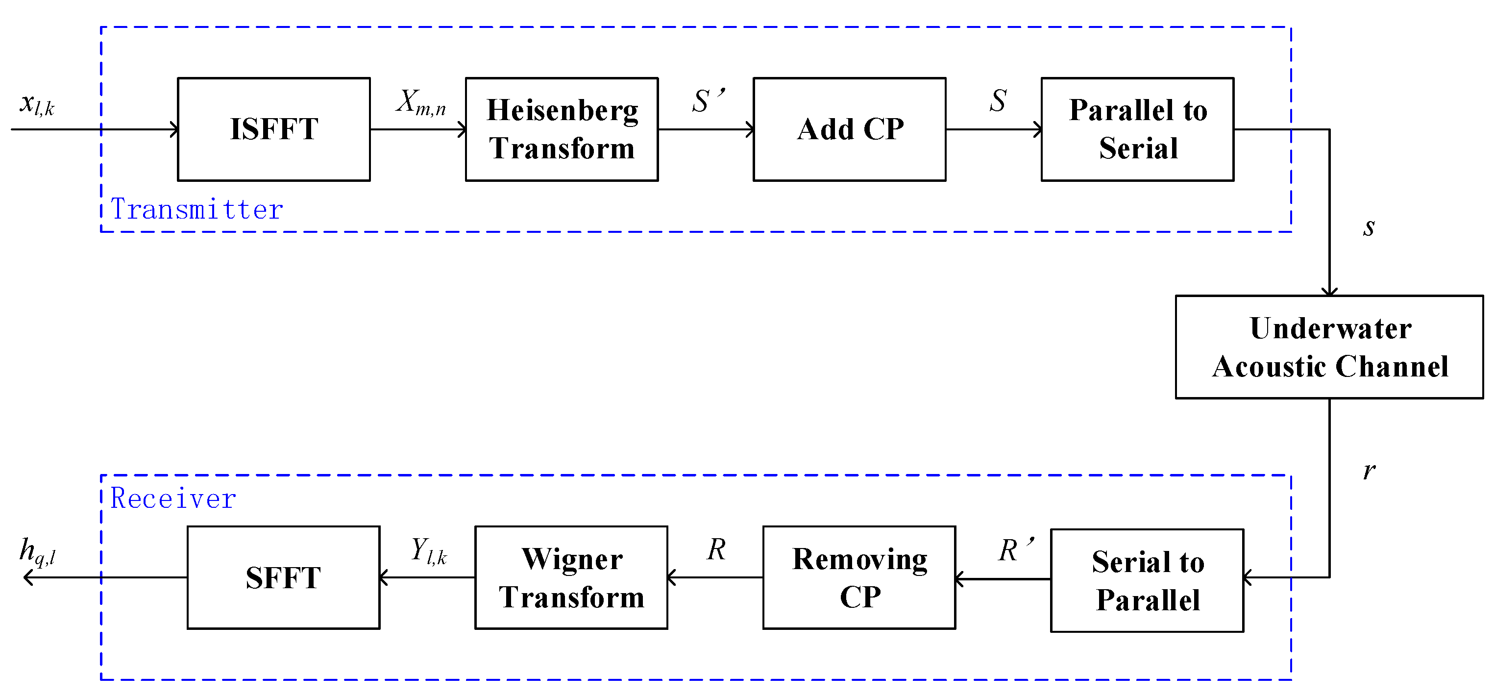
Figure 1. Underwater acoustic communication system based on OTFS.
Remotesensing 16 03157 g001
Figure 2. The received pilot symbols in DD domain.
Remotesensing 16 03157 g002
Figure 3. (a) The UWA channel impulse response; (b) The UWA channel scattering function.
Remotesensing 16 03157 g003
Figure 4. The estimation accuracy versus SNR of different single-direction adaptive algorithms with/without denoising method 1.
Remotesensing 16 03157 g004
Figure 5. (a) The estimation accuracy versus SNR of different single-direction adaptive algorithms. (b) The estimation accuracy versus SNR of single-direction and multidirection adaptive algorithms.
Remotesensing 16 03157 g005
Figure 6. The performance comparison of different single-direction adaptive algorithms with all kinds of denoising methods mentioned above.
Remotesensing 16 03157 g006
Figure 7. The experimental scene in July, Danjiangkou Lake.
Remotesensing 16 03157 g007
Figure 8. (a) The impulse response in the time-delay domain of the UWA channel; (b) The delay-Doppler Channel scattering function.
Remotesensing 16 03157 g008
Table 1. Parameters of the UWAc system.
ParameterValue
Water Depth500 (m)
Height of Transmitter200 (m)
Height of Receiver200 (m)
Distance between Transmitter to Receiver1000 (m)
Underwater Sound Velocity1500 (m/s)
Center Frequency f c 14.5 (kHz)
Bandwidth B5 (kHz)
Vessel Speed0 (m/s)
Spreading Factor1.7
Table 2. Parameters of OTFS.
ParameterValue
M64
N32
Bandwidth B5 (kHz)
Subcarrier Interval Δ f 78.1 (Hz)
Symbol Interval0.2 (ms)
Modulation TypeQPSK
M τ 32
N ν 32
Table 3. Parameters of Proposed Adaptive Channel Estimation Method.
ParameterValue
μ 0.5
α 0.9
β 0.1
γ 6 × 10 7
δ 0.01
ϵ 0.01
N h 500
Table 4. BER of Field Data Processed by Different Adaptive Channel Estimation Algorithms.
Number of FrameIPNLMS-TAIPNLMS-MA-MuD 1
100
200
300
400
500
600
700
86.73%0
900
1000
1100
1200
131.83%0
142.51%0
1510.44%7.29%
1600
Average1.34%0.46%
1 The step length of MA filter is 5.
Disclaimer/Publisher’s Note: The statements, opinions and data contained in all publications are solely those of the individual author(s) and contributor(s) and not of MDPI and/or the editor(s). MDPI and/or the editor(s) disclaim responsibility for any injury to people or property resulting from any ideas, methods, instructions or products referred to in the content.