Technical Note

Drone-Based Ground-Penetrating Radar with Manual Transects for Improved Field Surveys of Buried Ice

by
Adam R. Tjoelker
1,2,*,
Michel Baraër
3,
Eole Valence
4,
Bastien Charonnat
3,
Janie Masse-Dufresne
3,
Bryan G. Mark
1,2 and
Jeffrey M. McKenzie
4
1
Department of Geography, The Ohio State University, Columbus, OH 43210, USA
2
Byrd Polar and Climate Research Center, The Ohio State University, Columbus, OH 43210, USA
3
École de Technologie Supérieure (ÉTS), Montreal, QC H3C 1K3, Canada
4
Department of Earth and Planetary Sciences, McGill University, Montreal, QC H3A 0E8, Canada
*
Author to whom correspondence should be addressed.
Remote Sens. 2024, 16(13), 2461; https://doi.org/10.3390/rs16132461
Submission received: 28 May 2024 / Revised: 22 June 2024 / Accepted: 24 June 2024 / Published: 4 July 2024
(This article belongs to the Special Issue Remote Sensing of Cryosphere and Related Processes)

Abstract

:
The steep and unstable terrain found on debris-covered glaciers, rock glaciers, talus slopes, moraines and other proglacial features often make terrestrial ground-penetrating radar (GPR) surveys unsafe or cost-prohibitive. To address these challenges, this research introduces a novel approach for studying buried ice using multi-low-frequency drone-based GPR. Monostatic antennas of 50, 100, and 200 MHz were flown along a transect spanning a debris-covered glacier and an ice–debris complex at Shár Shaw Tagà (Grizzly Creek) in southwest Yukon, Canada. The drone-based results were compared to manual GPR at two locations along the transect. The two manual segments were conducted using the same radar system in a bi-static mode and included common mid-point (CMP) surveys. Overall, the drone-based radar successfully identified buried ice and enabled estimation of ice body thickness. Notably, CMP results confirmed layer characteristics and enabled depths to be measured across the entire drone-based transect. Discrimination of detail across a range of depths was made possible by comparing the three low frequencies, highlighting the possibility of using this method for future investigations of debris thickness in addition to quantifying buried ice. This study confirms the effectiveness of drone-based GPR combined with manual CMP for surveying ice beneath previously inaccessible terrain.

1. Introduction

1.1. Ground-Penetrating Radar for Surveying Buried Ice

Debris-covered ice is present on an estimated 44% of Earth’s glaciers (excluding Antarctica) and may account for 7.3% of the global mountain glacier area [1]. In addition to debris-covered glaciers, buried glacial ice is commonly found in deglaciating environments where retreating glaciers have left residual ice that is covered by sediments through paraglacial and gravitational processes [2]. Methods have been developed to improve the detection of buried ice, including the application of terrain models and deep learning methods to satellite remote sensing data [3,4]. Despite these advancements, high-quality field data are needed on the ground truth of the extent of buried ice. As warming continues to impact glaciers globally, heavily debris-covered features such as debris-covered glaciers and rock glaciers will become more important to quantify as hydrologic resources [5]. Additionally, the impacts of debris cover feedback on ice mass balance are inherently difficult to study and remain a poorly quantified part of glacier modeling efforts due to difficulties measuring buried ice melt [6,7].
Ground-penetrating radar (GPR) is a standard geophysical approach that has been used extensively over the last two and a half decades to detect and characterize buried massive ice in debris-covered glaciers, rock glaciers and permafrost [6,8,9,10,11]. However, past studies investigating the ice content of steep terrain using ground-based manual GPR surveys often feature a limited number of transects with paths determined by the landscape topography [12,13]. Airborne GPR, whether mounted on helicopters or fixed-wing aircraft, is a potential solution to overcome these challenges. For instance, a helicopter-mounted GPR has been successfully used to create a quasi-three-dimensional map of a rock glacier in the Swiss Alps using multiple hatched passes, a feat only achievable with an airborne system [14]. However, airborne options have most often been limited to mapping the depths of large glaciers and ice sheets due to high costs [15,16,17,18]. These surveys use lower-frequency radars for measuring glacier thickness and have a lower resolution as a result. In addition, most airborne GPR surveys conducted using aircraft or helicopters sacrifice spatial resolution as measurements are made at several tens of meters above the surface.
Altitude separation between airborne GPR and the surface can be reduced with recent advancements in relatively low-cost drone-based GPR [19]. Drone-based GPR systems have been used in recent years for snow hydrology surveys, where GPR enables undisturbed detection of strata within snowpack [20]. Fixed-wing drone-based ice-penetrating radar systems have also been developed for surveys of larger, mostly clean ice glaciers [21,22]. These systems use lower-energy radars which work well for mapping glacier thickness where there is limited debris coverage. More recently, rotary wing drone-based GPR has been developed for 3D and 4D coverage of mostly clean ice glacial tongues [23].
The development of drone-based GPR methods for the detection of buried glacial ice over complex terrain is a logical next step, building on the capability of drone-based radar technology. To the best of our knowledge there are no other publications that document the application of drone-based GPR for studying buried ice. The objective of this study is to provide the first test of the effectiveness of a drone-based radar survey to survey buried ice content in terrain that would be effectively inaccessible to ground-based GPR.

1.2. Shár Shaw Tagà (Grizzly Creek) Field Site

This study was conducted within a deglaciating sub-catchment of Shár Shaw Tagà valley in southwest Yukon, Canada. The study area is located on the Kluane and White River First Nation territory within Kluane National Park and Reserve. In the literature, Shár Shaw Tagà is referred to as Grizzly Creek, its non-indigenous toponym. The sub-catchment exhibits a glacier to debris-covered glacier to rock glacier continuum typical of the St. Elias Mountains greenbelt [24]. Moving down the valley, the clean glacier ice above 2100 m a.s.l. transitions to a debris-covered glacier and an ice–debris complex (as described by Bolch et al. [25]) between 2100 and 1900 m a.s.l, and then to a rock glacier from 1900 to 1700 m a.s.l., where the sub-catchment meets the main valley (Figure 1). This sub-catchment at Shár Shaw Tagà remains unnamed by the Kluane First Nation community to the best of our knowledge. It was identified as the “Ice-cored moraine and rock glacier” in initial fieldwork in the area by Johnson [24] and as the “glacier debris system rock glacier” with a “tributary glacier” by Evin et al. [26].
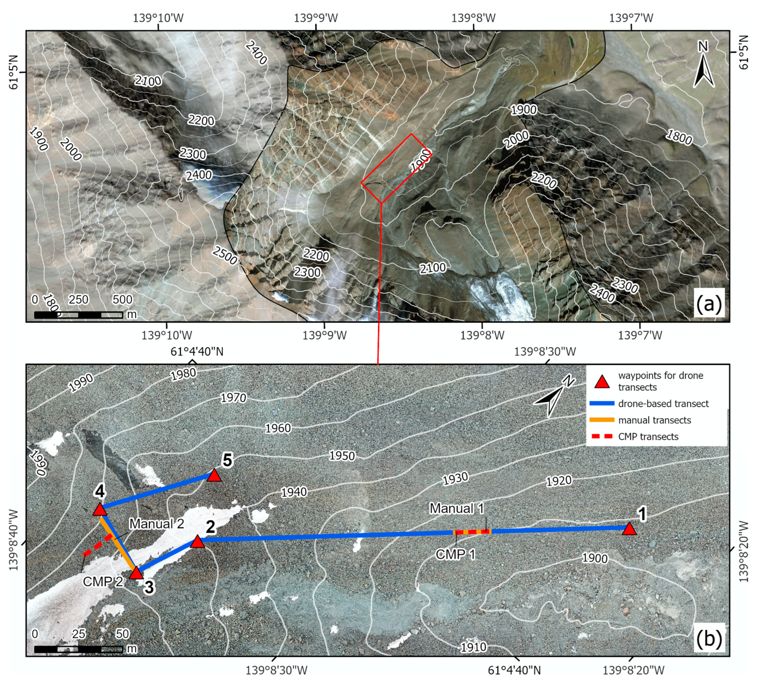
The drone-based GPR transect for this study is located along the transition from the debris-covered glacier to the ice–debris complex (Figure 2). Talus slopes intersect with the debris-covered glacier, and morainic accumulations near the study transect, obscuring clear distinctions between these features. At the upper end of the transect, exposed ice cliffs indicate the presence of buried glacial ice. The transect location was chosen to evaluate the continuity of buried ice between the exposed ice cliffs and the ice beneath the unstable talus, downhill from the end of the debris-covered glacier.

2. Materials and Methods

2.1. Drone-Based GPR

During June 2023, a Radar Systems Zond Aero LF GPR was flown in a monostatic configuration onboard a DJI M600 Pro drone along a 430 m transect (Figure 2). Three complete passes of the transect were flown, each with one of the 50, 100, and 200 MHz unshielded dipole antennas. A laser altimeter was used to set a target altitude of 5 m above the ground, to prevent collision with boulders on the undulating terrain. The Zond Aero LF radar was integrated with the DJI M600 using an SPH Engineering SkyHub 3 onboard computer with firmware version 2.13.1 and UgCS version 4.15 flight planning software. Drone-borne radargrams were georeferenced using the post-processed kinematic (PPK) method, with signals collected by an onboard Emlid Reach M2 RTK module and an Emlid Reach RS2+ base station. The pre-programmed flight paths of the drone followed the path indicated in Figure 2 for the three antennas. The drone transect paths after post-processing were shown to remain within 3 m of each other.

2.2. Manual Ground-Penetrating Radar

The Zond Aero LF system was operated in a bi-static configuration for ground-based manual surveys, serving as a reference for the drone-based configuration. The detachable nature of the antenna and receiver in the bi-static operation allowed for a common mid-point (CMP) survey at each of two manual transects to aid in layer identification and thickness estimation. The first manual and CMP transects, “Manual 1” and “CMP 1,” were conducted along the same 20 m span of the drone-based transect on the ice-cored moraine and talus slope. The second manual and CMP transects, “Manual 2” and “CMP 2,” were conducted on the debris-covered glacier in the upper portion of the transect near the exposed ice cliffs. The antenna configurations for both drone-based CMP and manual GPR transects are shown in the Supplementary Information in Table S1.
The Manual 2 GPR transect was aligned as close as possible with the path of the drone but did not correspond perfectly to the drone-based transect due to the steep slope on the debris-covered glacier (Figure 2b). The Manual 2 GPR transect spanned a 40 m path upslope onto the debris-covered glacier. Unlike the CMP 1 transect, the 20 m CMP 2 transect did not align with the Manual 2 transect. CMP 2 was conducted perpendicular to the manual transect, roughly parallel to the slope of the debris-covered glacier for safety and practical reasons. Conducting the CMP perpendicular to the slope at this location avoided the issue of varying interface depth, allowing for a more consistent substrate beneath the CMP 2 transect.

2.3. Drone Photgrammetry and DEM

Aerial photogrammetry with 620 images of the study area was conducted using a DJI Mavic 2 Pro within two days following the drone-based GPR data collection. Ground control points (n = 9) and the ends of the CMP and manual transects were surveyed using an Emlid Reach M2 RTK module connected to an Emlid Reach RS2+ base station. The orthomosaic and digital elevation model (DEM) used for the survey map and terrain rectification of the radargrams were produced using Pix4D Mapper and are shown in Figure 2b.

2.4. Radar Data Processing

Subsequent processing of drone-based and manual radargrams was conducted in the Radar Systems Prism2 software version 2.70.05. All radargrams underwent the same processing sequence: (i) background removal; (ii) Ormsby bandpass filter targeting the central frequency +/− 50%; and (iii) linear gain adjustment for optimal readability. Reflections at layer interfaces were picked manually. In addition, terrain rectification was applied to both the drone-based transects based on PPK outputs and to the manual transect using elevations from the DEM produced for the study area. Calculation of velocities from the CMP transects and depth correction followed methods used in comparable ice–debris environments [13,28,29]. The layer velocities were applied across the drone-based transect, enabling depths to be compared across the two methods. Interpretation of GPR facies and debris thickness followed standard interpretation methods for debris-covered glaciers (e.g., [6,30]). Processed radargrams without annotations can be found in the Supplementary Materials of this article.

2.5. Measuring Buried Ice Heights and Depths

Velocities determined through the CMP analysis enabled buried ice heights and depths of the ice base reflector to be compared between the drone-based and Manual 1 transects. These heights and depths were calculated from the GPR traces by multiplying one-half the two-way travel time between the top and bottom of ice and debris layers by the respective velocities derived from the CMP analysis. The calculation of velocities allowed the depths to the base reflector and the height of the buried ice to be calculated. The interfaces between each layer for calculating the two-way travel time were manually picked from the data. Depth measurements were taken at points 0 m, 10 m and 20 m along the CMP 1 transect and compared to the same locations in the drone-based radargrams. These locations were chosen to compare the results at three (3) points evenly spaced along the CMP transect.

3. Results

3.1. Drone-Based Radargrams

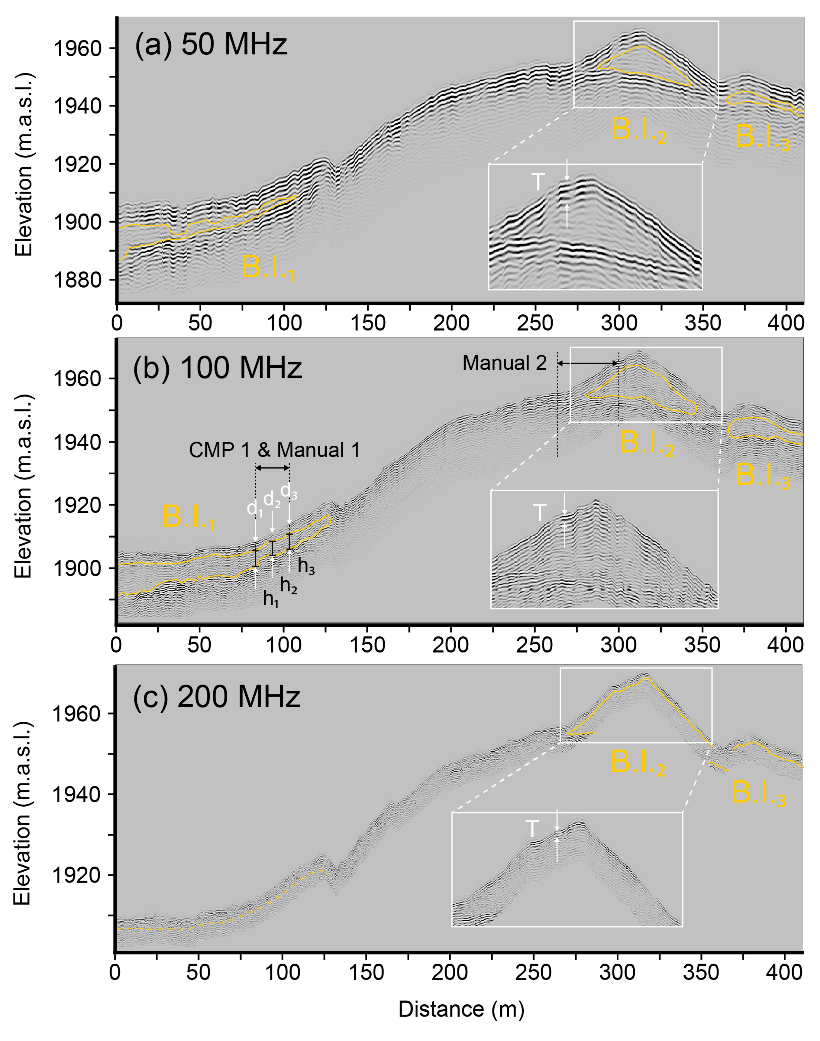
The processed and annotated drone-based radargrams for all three frequencies are shown in Figure 3. Three major areas of buried ice, B.I.1, B.I.2 and B.I.3, are identified along the drone-based transects as voids of low reflection observed with all three antennas. The detection of a base reflector beneath the ice bodies was possible using only the 50 MHz and 100 MHz antennas. The delineated shape of the ice bodies varies slightly from antenna to antenna, with the 50 MHz antenna yielding the thickest debris estimates due to its inherent low resolution. Surface multiples can be seen in the 100 MHz and 50 MHz radargrams caused by repeated reflections from the near surface. This noise in the 100 MHz and 50 MHz radargrams makes determination of the debris layer thickness, T, difficult to discern. On the top of the debris-covered glacier, at B.I.2, the apparent thickness shown in the radargram can be compared across the results from the three frequencies. In the 200 MHz radargram, the debris layer appears thinner than that shown in the two lower frequencies, showing a thickness closer to the field observation of approximately 30 cm depth at the top of the debris-covered glacier.

3.2. Manual Radargrams

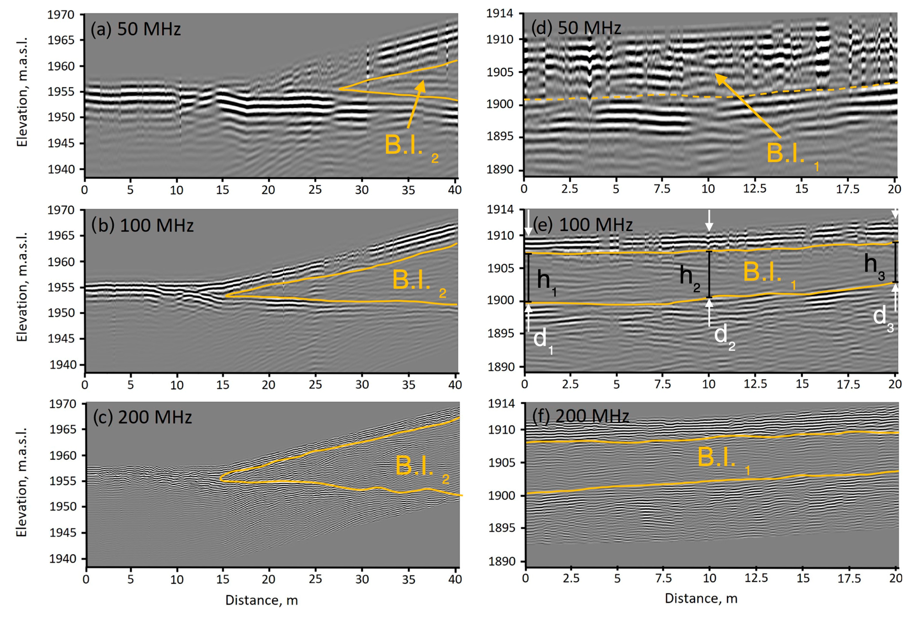
Each of the manual GPR transects surveyed show similar locations and thicknesses of the ice masses (Figure 4). Comparing the results from the drone-based radargrams in Figure 3, the manual GPR radargrams from the Manual 2 transect (Figure 4a–c), agree with the shape and location of B.I.2. The improved quality of the manual transect radargrams is likely due to the coupling between the antenna and the surface, reducing the signal loss and enabling the 200 MHz antenna to penetrate deeper into the debris-covered glacier. Radargrams from the Manual 1 transect along the ice-cored moraine also capture the same shape and location of the B.I.1 feature identified in the drone-based transects. The B.I.1 at this location is covered by a thicker debris layer than what was found on the debris-covered glacier. Overall, the 200 MHz and 100 MHz radargrams show a 5–7 m thick layer of ice, while the 50 MHz radargram is particularly noisy, confounding the identification of a clear ice layer.
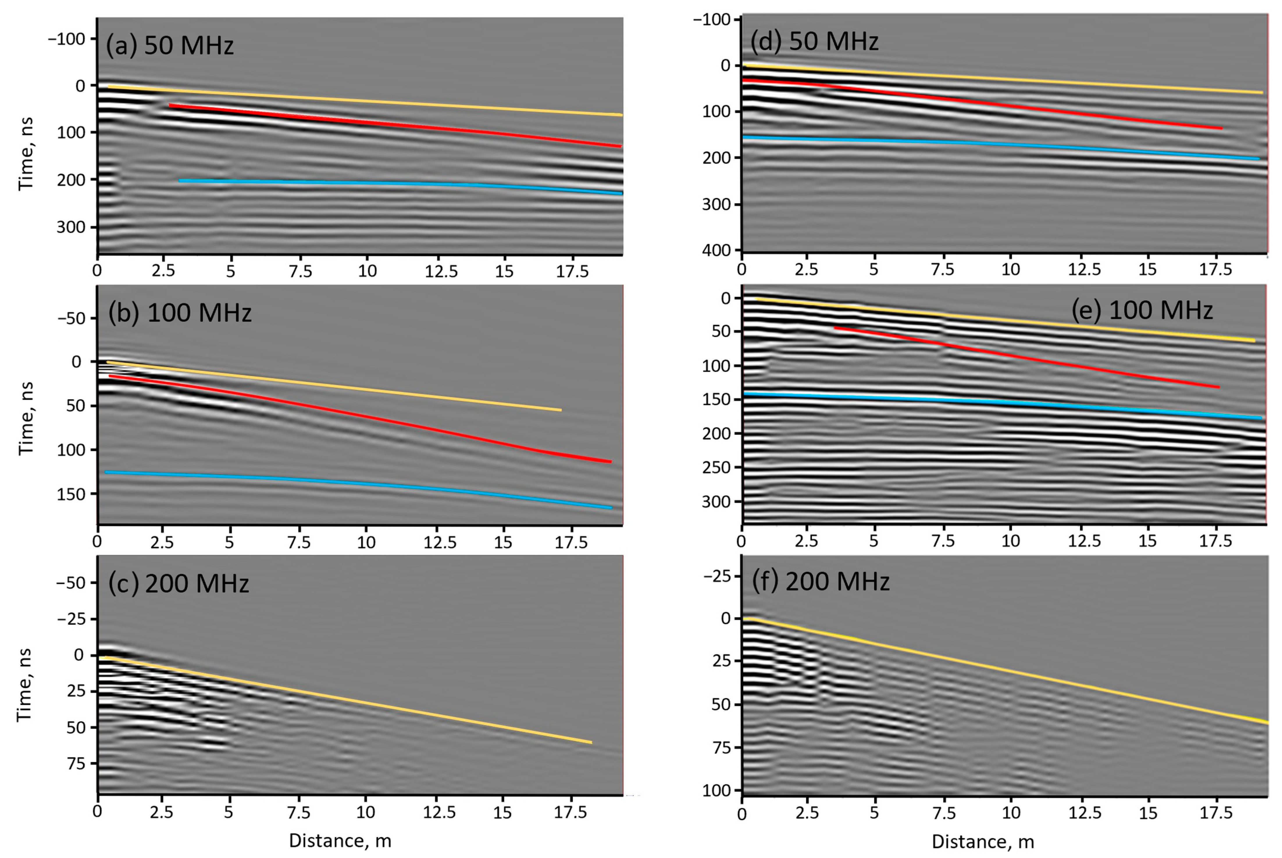
The radargrams collected at the two CMP transects were used to compute the relative permittivity and the wave velocities and estimate the thickness of both debris and ice layers (Figure 5). The 50 and 100 MHz CMP transects showed clear signal trajectories. The 200 MHz CMP transects did not provide clear separations between the different layers, preventing the estimation of layer characteristics with this antenna. The values for the thickness, velocity, and relative permittivity of the ice and debris layers at each CMP transect are presented in Table 1. The values of permittivity for ice range from 2.9 to 4.1 and debris primitivities range from 3.3 to 4.7.

3.3. Height and Depth Measurements

At the 0 m, 10 m and 20 m distances along the 100 MHz Manual 1 transect, ice body heights of h1 = 8.5 m, h2 = 7 m and h3 = 6.8 m were estimated. The 100 MHz frequency was chosen for making comparisons between the airborne and ground observations since it was the best compromise between depth and resolution. The 200 MHz radar did not have sufficient penetration in the drone-based configuration and the 50 MHz radar sacrificed resolution.
The corresponding 100 MHz drone-based GPR heights sampled resulted in h1 = 10.3 m, h2 = 9.7 m and h3 = 7.7 m. Comparing the ice layer height measurements at each location, the mean absolute difference between the measurements is 1.8 m. Measurements of the depth of the ice base reflector at the same locations were calculated by adding the thickness of the surficial debris layer to the buried ice layer height. Total depths from the Manual 1 transect were found to be d1 = 12.9 m, d2 = 10 m and d3 = 9.8 m. Drone-based depths were calculated as d1 = 12.1 m, d2 = 11.8 m and d3 = 10.5 m. The mean absolute difference between the depth measurements was found to be 1.1 m. Differences between heights and depths measured with the drone and manual GPR are discussed further in the discussion in Section 4.2.

4. Discussion

4.1. CMP Results

The relative permittivity values for ice across both transects range between 2.9 and 4.1, aligning with commonly reported values in the literature. For example, Thomson et al. [31] place relative permittivity for ice under debris between three and five, while Wu and Liu [29] report values between three and four. The results indicate that CMP1 (4.7 to 4.5) and CMP2 (3.7 to 3.3) exhibit different relative permittivity for the debris layers, highlighting the variability reported in the literature for such media [32]. Overall, the addition of CMP to the aerial GPR acquired in this study enable high confidence in the layers of ice and debris identified in the radargrams across the drone-based transect and allow ice thickness measurements.

4.2. Differences between Drone and Manual GPR Measurements

Discrepancies between the depths and heights measured in the drone and manual radargrams can be linked to (i) limitations inherent to the airborne radar method used and (ii) the uncertainty introduced by the surface and debris media which impact both GPR methods. The mean absolute error is 1.8 m between the ice heights measured and 1.1 m between the base reflector depths. It is important to note that there is still uncertainty associated with the manual observations, so the manual measurements cannot be considered ground truth. The uncertainty in georeferencing uncovered after post-processing the exact position of the drone indicate that the measurements were not always taken at exactly the same spot between the manual and drone-based surveys. Future work could be carried out to improve transect positioning through RTK. Digging debris pits for ground truthing would also allow for accurate validation of debris thickness measurements.
The sources of uncertainty associated with the drone-based operation alone limit the performance of the drone radar compared to manual surveys, but these considerations must be acknowledged when deploying drone-based radar beyond where manual surveys would be possible. Drone-based GPR also enables much larger areas to be covered at the same time, improving the efficiency of field surveys. In this case, it is important to consider the tradeoffs in the data quality associated with an aerial GPR survey. The following two sections address the possible uncertainties associated with the airborne method and the field conditions.

4.2.1. Uncertainty Related to Aerial GPR Operation

The first noted source of uncertainty in the drone-based radargrams is the user identification of the air/ground interface. When the antenna is decoupled from the surface during an aerial GPR survey, the exact position of the ground is more difficult to determine due to the separation of the antenna from the surface [33]. This error impacts the measurements used in our study to locate the surface of the debris layer, which was used for calculating the debris thickness and total depth of the ice base reflector.
The height of the drone above the surface also presents a challenge for the quality of the results. Increasing the separation of the GPR antenna from the surface is known to result in a lower signal to noise ratio (SNR) because of the increase in the effective antenna beam pattern footprint [34]. This altitude effect reduces the precision that can be used to identify small targets and causes subsurface features to have locational error since reflections will not always come from directly beneath the antenna. The altitude of the drone varied due to the altimeter compensation lag over the rough debris surface, which contained large boulders. This effect complicates the interpretation of the GPR through a variable layer of error.
Additionally, aerial GPR antennas that are decoupled from the surface present the additional challenge of high power loss caused during the first reflection at the air/ground interface [35]. The change in permittivity between the air and ground combined with the debris surface roughness both contribute to power loss, which limits the penetration of the radar. This factor contributes to the issue seen with the 200 MHz antenna used in the drone-based configuration in the present study, where penetration depth is dramatically limited when compared to the corresponding manual surface GPR transect. For example, in the drone-based GPR in Figure 3, the location of the debris/ice interface is not clear and indicated by a dotted line, but it is clearly visible along the Manual 1 transect in Figure 4.
Reflections from outside the survey plane are an additional consideration for airborne radar surveys over steep terrain, such as the terrain at the study site at Shár Shaw Tagà. The pitch and roll of the drone also contribute to additional reflections originating outside the mapped path of the drone. Migration techniques have been described in the literature to address these concerns [36], but these methods were not applied to the standard GPR processing conducted to produce the radargrams used for this study. Migration was not applicable for our study since it would involve the development of new techniques to account for the chaotic surface media comprising various sized rocks and boulders in addition to the surface topography. Future research could address these concerns to improve radargrams obtained from an airborne GPR over steep and rough terrain.
The effect of the target altitude above the surface was not investigated in this study due to the limited flight time permitted by field conditions and battery life. Additionally, the high risk of collision with large boulders scattered on the steep slopes prevented testing the GPR at lower altitudes. It can be concluded that the target altitude separation of 5 m used for the drone-based transects contributed to these described errors of lower SNR and diminished capacity to identify the ice–debris interface.

4.2.2. Other Sources of Uncertainty

Beyond the error originating from airborne GPR operation, conditions in the field contributed to potential uncertainties. The first of these sources originates from the potential misinterpretation of interfaces [30]. This misinterpretation could be caused by a potential integration of small debris into the top layer of the ice, limiting the dielectric contrast between the ice and debris in the radargrams and causing a weaker reflection. This effect would be present with the data acquired using both methods but would have an increased effect with the drone-based GPR which already experiences higher energy loss due to antenna decoupling from the surface.
The manual GPR measurements presented additional potential uncertainty due to difficulty maintaining a consistent antenna position over the surface [37]. Changes in angle and height varied as the antenna was moved over the irregular rocky surface. The noisy data from the 50 MHz radargram in Figure 4 can be explained by the technical challenge of maintaining a consistent antenna position over the ground when handling larger antennas exceeding 2 m in length over steep, unstable terrain. Accidental collisions of the antenna with the surface were difficult to avoid when conducting the 50 MHz survey and, as a result, caused the drone-based GPR to outperform the manual radar in this case.
The thickness of the surficial debris layer varied from 30 cm to a few meters across the study area. Depending on the antenna frequency used, the minimum depth of investigation varies based on the wavelength of the radar. The thinner areas of debris, especially at the top of the debris-covered glacier where debris is as thin as 30 cm, would prevent the two lower-frequency antennas from being able to resolve the debris–ice interface. Wave theory indicates that the best vertical resolution that can be achieved is one-quarter of the dominant wavelength, which would be around 0.75 m for the 100 MHz antenna [38]. This detection limit impacts the measurements of the debris thickness estimations and the calculations of total ice body height reported in the results.
If the 200 MHz radar had been able to identify the ice–debris interface, it could be able to be used to measure debris thickness more accurately than the 100 MHz antenna. However, the 200 MHz radar did not have sufficient penetration in the drone-based transect to facilitate a direct comparison between the drone and ground-based radar transects.

4.3. Methodological Recommendations

The results of this study demonstrate that the detection of large continuous buried ice bodies is particularly effective using drone-based GPR. The dielectric contrast of the ice and the surrounding media at this site permits effective detection of the ice base reflector. Improvements in processing and field collection could likely further improve the measurement of the debris layer thickness given the difficulties seen with surface multiples and complex reflections from the air/ground interface.
For geophysical investigations using drone-based GPR, ice detection is most effective when operating the drone as close to the surface as possible, at slow speeds, with flat terrain that has a high dielectric contrast between the media and ice. Thinner debris layers permit easier detection of ice compared to thicker debris layers.
For thinner debris layers, higher-frequency radars should have sufficient penetration to resolve the base reflector. For example, in this study, the 200 MHz drone-based radar was able to detect the base reflector below the thinner debris near the Manual 2 transect and was not able to detect the base reflector to the deeper debris along Manual 1 transect. Specific frequencies for drone-based GPR investigations should be chosen specifically for the field conditions present at a study site.
As discussed in the methods and results, the thickness of the debris layer was not directly measured in this study and was not the focus of the investigation. However, given the results seen with the surface multiples and difficulty discerning the debris layer thickness using the drone-based GPR, it could be suggested that finer debris would likely improve the determination of the surface reflector and could contribute to more effective determination of debris layer thickness when compared to manual GPR.

5. Conclusions

This study demonstrates the effectiveness of drone-based GPR for detecting and measuring buried ice where traditional manual GPR methods would not be possible. The inclusion of the two manual transects with a CMP survey using the same radar system provide a valuable comparison of the performance of the radar in airborne and ground-based operations. Comparing the two methods, the drone-based radargrams agree with the location and shape of buried ice detected in the manual GPR performed at the same frequencies and locations. The addition of CMP along the two manual transects enabled depths to be calculated accurately using the drone-based radar.
Across three measurements of the total height and depth of B.I.1, the drone-based GPR is within 1.8 m of the height and 1.1 m of the depths determined using the manual GPR on average. Despite these discrepancies, which can likely be improved upon with additional processing and methodological improvements, the ability to detect buried ice over complex and dangerous terrain provides significant opportunities for future investigations of processes and changes in debris-covered glacier systems.
Acknowledging the inherent limitations in data resolution when performing GPR with an elevated antenna that is decoupled from the surface, the drone-based methods matched the detection ability of the manual radar. Notably, the 50 MHz drone-based radar outperformed the manual antenna of the same frequency, a testament to the difficulty of performing GPR surveys in challenging terrain. However, noise and signal loss caused by the lack of antenna coupling with the surface when using the drone-based radar complicated efforts to determine debris layer thickness in the radargrams. Future research directions building upon this work point towards the application of more advanced algorithms for processing radargrams to improve the near-surface signal quality, enabling more precise measurements of debris layer thickness.

Supplementary Materials

The following supporting information can be downloaded at https://www.mdpi.com/article/10.3390/rs16132461/s1: Table S1: Configuration parameters for the Zond Aero LF GPR system; Figure S1: The 50 MHz raw processed radargram; Figure S2: The 100 MHz raw processed radargram; Figure S3: The 200 MHz raw processed radargram. Figure S4: Manual Transect 1 50 MHz Raw. Figure S5: Manual Transect 1 100 MHz Raw. Figure S6: Manual Transect 1 200 MHz Raw. Figure S7: Manual Transect 2 50 MHz Raw. Figure S8: Manual Transect 2 100 MHz Raw. Figure S9: Manual Transect 2 200 MHz Raw.

Author Contributions

Conceptualization, A.R.T., M.B., E.V. and B.C.; data curation, E.V.; formal analysis, A.R.T., M.B. and E.V.; funding acquisition, M.B., J.M.M. and B.G.M.; investigation, A.R.T., M.B., E.V. and B.C; methodology, A.R.T., M.B., E.V. and B.C; project administration, M.B. and J.M.-D.; supervision, M.B., B.G.M., J.M.M. and J.M.-D.; visualization, A.R.T., M.B., E.V. and B.C; writing—original draft, A.R.T.; writing—review and editing, A.R.T., M.B., E.V., B.C., J.M.-D., B.G.M. and J.M.M. All authors have read and agreed to the published version of the manuscript.

Funding

This research was funded by the Natural Sciences and Engineering Research Council of Canada, grant numbers RGPIN-2020-05612 and RGPNS-2020-05612, and by Natural Resources Canada—Polar Continental Shelf Program, grant number 62723. Funding for the expedition was also provided by the Geochemistry and Geodynamics Research Center (GEOTOP) Quebec and The Ohio State University Department of Geography.

Data Availability Statement

The raw GPR data from this survey are available for download at https://zenodo.org/records/10689923 [39].

Acknowledgments

We would like to thank Kluane First Nation and White River First Nation for the opportunity to conduct research on their land and acknowledge their long history and relationship with the land. We would also like to thank the Arctic Institute of North America and the University of Calgary for providing us service and access to their facilities at Kluane Lake Research Station. Permission to conduct research in Kluane National Park and Reserve was provided by Parks Canada.

Conflicts of Interest

The authors declare no conflicts of interest. The funders had no role in the design of the study; in the collection, analyses, or interpretation of data; in the writing of the manuscript; or in the decision to publish the results.

References

  1. Herreid, S.; Pellicciotti, F. The State of Rock Debris Covering Earth’s Glaciers. Nat. Geosci. 2020, 13, 621–627. [Google Scholar] [CrossRef]
  2. Everest, J.; Bradwell, T. Buried Glacier Ice in Southern Iceland and Its Wider Significance. Geomorphology 2003, 52, 347–358. [Google Scholar] [CrossRef]
  3. Paul, F.; Huggel, C.; Kääb, A. Combining Satellite Multispectral Image Data and a Digital Elevation Model for Mapping Debris-Covered Glaciers. Remote Sens. Environ. 2004, 89, 510–518. [Google Scholar] [CrossRef]
  4. Xie, Z.; Haritashya, U.K.; Asari, V.K.; Young, B.W.; Bishop, M.P.; Kargel, J.S. GlacierNet: A Deep-Learning Approach for Debris-Covered Glacier Mapping. IEEE Access 2020, 8, 83495–83510. [Google Scholar] [CrossRef]
  5. Jones, D.B.; Harrison, S.; Anderson, K.; Whalley, W.B. Rock Glaciers and Mountain Hydrology: A Review. Earth-Sci. Rev. 2019, 193, 66–90. [Google Scholar] [CrossRef]
  6. Mertes, J.R.; Thompson, S.S.; Booth, A.D.; Gulley, J.D.; Benn, D.I. A Conceptual Model of Supra-Glacial Lake Formation on Debris-Covered Glaciers Based on GPR Facies Analysis: GPR Facies Analysis of Spillway Lake, Ngozumpa Glacier, Nepal. Earth Surf. Process. Landf. 2017, 42, 903–914. [Google Scholar] [CrossRef]
  7. Strickland, R.M.; Covington, M.D.; Gulley, J.D.; Kayastha, R.B.; Blackstock, J.M. Englacial Drainage Drives Positive Feedback Depression Growth on the Debris-Covered Ngozumpa Glacier, Nepal. Geophys. Res. Lett. 2023, 50, e2023GL104389. [Google Scholar] [CrossRef]
  8. Berthling, I.; Etzelmüller, B.; Isaksen, K.; Sollid, J.L. Rock Glaciers on Prins Karls Forland. II: GPR Soundings and the Development of Internal Structures. Permafr. Periglac. Process. 2000, 11, 357–369. [Google Scholar] [CrossRef]
  9. Brandt, O.; Langley, K.; Kohler, J.; Hamran, S.-E. Detection of Buried Ice and Sediment Layers in Permafrost Using Multi-Frequency Ground Penetrating Radar: A Case Examination on Svalbard. Remote Sens. Environ. 2007, 111, 212–227. [Google Scholar] [CrossRef]
  10. De Pascale, G.P.; Pollard, W.H.; Williams, K.K. Geophysical Mapping of Ground Ice Using a Combination of Capacitive Coupled Resistivity and Ground-Penetrating Radar, Northwest Territories, Canada. J. Geophys. Res. 2008, 113, F02S90. [Google Scholar] [CrossRef]
  11. Degenhardt, J.J. Development of Tongue-Shaped and Multilobate Rock Glaciers in Alpine Environments—Interpretations from Ground Penetrating Radar Surveys. Geomorphology 2009, 109, 94–107. [Google Scholar] [CrossRef]
  12. Capt, M.; Bosson, J.-B.; Fischer, M.; Micheletti, N.; Lambiel, C. Decadal Evolution of a Very Small Heavily Debris-Covered Glacier in an Alpine Permafrost Environment. J. Glaciol. 2016, 62, 535–551. [Google Scholar] [CrossRef]
  13. Petersen, E.I.; Levy, J.S.; Holt, J.W.; Stuurman, C.M. New Insights into Ice Accumulation at Galena Creek Rock Glacier from Radar Imaging of Its Internal Structure. J. Glaciol. 2020, 66, 1–10. [Google Scholar] [CrossRef]
  14. Merz, K.; Green, A.G.; Buchli, T.; Springman, S.M.; Maurer, H. A New 3-D Thin-skinned Rock Glacier Model Based on Helicopter GPR Results from the Swiss Alps. Geophys. Res. Lett. 2015, 42, 4464–4472. [Google Scholar] [CrossRef]
  15. Blindow, N.; Salat, C.; Casassa, G. Airborne GPR Sounding of Deep Temperate Glaciers — Examples from the Northern Patagonian Icefield. In Proceedings of the 2012 14th International Conference on Ground Penetrating Radar (GPR), Shanghai, China, 4–8 June 2012; pp. 664–669. [Google Scholar]
  16. Casassa, G.; Rodríguez, J.L.; Blindow, N. Airborne GPR on High Andean Glaciers—First Results from 6000 m Altitude. In Proceedings of the 15th International Conference on Ground Penetrating Radar, Brussels, Belgium, 30 June–4 July 2014; pp. 728–733. [Google Scholar]
  17. Langhammer, L.; Rabenstein, L.; Schmid, L.; Bauder, A.; Grab, M.; Schaer, P.; Maurer, H. Glacier Bed Surveying with Helicopter-Borne Dual-Polarization Ground-Penetrating Radar. J. Glaciol. 2019, 65, 123–135. [Google Scholar] [CrossRef]
  18. Zamora, R.; Ulloa, D.; Garcia, G.; Mella, R.; Uribe, J.; Wendt, J.; Rivera, A.; Gacitúa, G.; Casassa, G. Airborne Radar Sounder for Temperate Ice: Initial Results from Patagonia. J. Glaciol. 2009, 55, 507–512. [Google Scholar] [CrossRef]
  19. Francke, J.; Dobrovolskiy, A. Challenges and Opportunities with Drone-Mounted GPR. In First International Meeting for Applied Geoscience & Energy Expanded Abstracts; Society of Exploration Geophysicists, Denver, CO, USA and Virtual, 26 September–1 October 2021; Society of Exploration Geophysicists: Houston, TX, USA, 2021; pp. 3043–3047. [Google Scholar]
  20. Valence, E.; Baraer, M.; Rosa, E.; Barbecot, F.; Monty, C. Drone-Based Ground-Penetrating Radar (GPR) Application to Snow Hydrology. Cryosphere 2022, 16, 3843–3860. [Google Scholar] [CrossRef]
  21. Leuschen, C.; Hale, R.; Keshmiri, S.; Yan, J.B.; Rodriguez-Morales, F.; Mahmood, A.; Gogineni, S. UAS-Based Radar Sounding of the Polar Ice Sheets. IEEE Geosci. Remote Sens. Mag. 2014, 2, 8–17. [Google Scholar] [CrossRef]
  22. Teisberg, T.O.; Schroeder, D.M.; Broome, A.L.; Lurie, F.; Woo, D. Development of a Uav-Borne Pulsed ICE-Penetrating Radar System. In Proceedings of the IGARSS 2022—2022 IEEE International Geoscience and Remote Sensing Symposium, Kuala Lumpur, Malaysia, 17–22 July 2022; pp. 7405–7408. [Google Scholar]
  23. Ruols, B.; Baron, L.; Irving, J. Development of a Drone-Based Ground-Penetrating Radar System for Efficient and Safe 3D and 4D Surveying of Alpine Glaciers. J. Glaciol. 2023, volume, 1–12. [Google Scholar] [CrossRef]
  24. Johnson, P.G. Glacier-Rock Glacier Transition in the Southwest Yukon Territory, Canada. Arct. Alp. Res. 1980, 12, 195. [Google Scholar] [CrossRef]
  25. Bolch, T.; Rohrbach, N.; Kutuzov, S.; Robson, B.A.; Osmonov, A. Occurrence, Evolution and Ice Content of Ice-debris Complexes in the Ak-Shiirak, Central Tien Shan Revealed by Geophysical and Remotely-sensed Investigations. Earth Surf. Process. Landf. 2019, 44, 129–143. [Google Scholar] [CrossRef]
  26. Evin, M.; Fabre, D.; Johnson, P.G. Electrical Resistivity Measurements on the Rock Glaciers of Grizzly Creek, St Elias Mountains, Yukon. Permafr. Periglac. Process. 1997, 8, 179–189. [Google Scholar] [CrossRef]
  27. Porter, C.; Howat, I.; Noh, M.-J.; Husby, E.; Khuvis, S.; Danish, E.; Tomko, K.; Gardiner, J.; Negrete, A.; Yadav, B.; et al. ArcticDEM—Mosaics, Version 4.1 2023; Polar Geospatial Center: Saint Paul, MN, USA, 2023. [Google Scholar]
  28. McCarthy, M.; Pritchard, H.; Willis, I.; King, E. Ground-Penetrating Radar Measurements of Debris Thickness on Lirung Glacier, Nepal. J. Glaciol. 2017, 63, 543–555. [Google Scholar] [CrossRef]
  29. Wu, Z.; Liu, S. Imaging the Debris Internal Structure and Estimating the Effect of Debris Layer on Ablation of Glacier Ice. J. Geol. Soc. India 2012, 80, 825–835. [Google Scholar] [CrossRef]
  30. Giese, A.; Arcone, S.; Hawley, R.; Lewis, G.; Wagnon, P. Detecting Supraglacial Debris Thickness with GPR under Suboptimal Conditions. J. Glaciol. 2021, 67, 1108–1120. [Google Scholar] [CrossRef]
  31. Thomson, L.I.; Osinski, G.R.; Pollard, W.H. The Dielectric Permittivity of Terrestrial Ground Ice Formations: Considerations for Planetary Exploration Using Ground-penetrating Radar. J. Geophys. Res. 2012, 117, 2012JE004053. [Google Scholar] [CrossRef]
  32. Meng, T.M.; Petersen, E.I.; Holt, J.W. Rock Glacier Composition and Structure from Radio Wave Speed Analysis with Dipping Reflector Correction. J. Glaciol. 2023, 69, 639–657. [Google Scholar] [CrossRef]
  33. Noviello, C.; Gennarelli, G.; Esposito, G.; Ludeno, G.; Fasano, G.; Capozzoli, L.; Soldovieri, F.; Catapano, I. An Overview on Down-Looking UAV-Based GPR Systems. Remote Sens. 2022, 14, 3245. [Google Scholar] [CrossRef]
  34. Booth, A.D.; Koylass, T.M. Drone-Mounted Ground-Penetrating Radar Surveying: Flight-Height Considerations for Diffraction-Based Velocity Analysis. Geophysics 2022, 87, WB69–WB79. [Google Scholar] [CrossRef]
  35. Lambot, S.; Antoine, M.; Vanclooster, M.; Slob, E.C. Effect of Soil Roughness on the Inversion of Off-ground Monostatic GPR Signal for Noninvasive Quantification of Soil Properties. Water Resour. Res. 2006, 42, 2005WR004416. [Google Scholar] [CrossRef]
  36. Dujardin, J.-R.; Bano, M. Topographic Migration of GPR Data: Examples from Chad and Mongolia. Comptes Rendus. Géoscience 2013, 345, 73–80. [Google Scholar] [CrossRef]
  37. Conyers, L.B.; Goodman, D. Ground-Penetrating Radar: An Introduction for Archaeologists; Altamira Press: London, UK, 1997. [Google Scholar]
  38. Sheriff, R.E. Limitations on Resolution of Seismic Reflections and Geologic Detail Derivable from Them1. In Seismic Stratigraphy—Applications to Hydrocarbon Exploration; American Association of Petroleum Geologists: Tulsa, OK, USA, 1977; ISBN 978-1-62981-205-2. [Google Scholar]
  39. Baraer, M. GPR Data Collected at Shar Shaw Tagà in June 2023; Zenodo: Geneva, Switzerland, 2024. [Google Scholar]
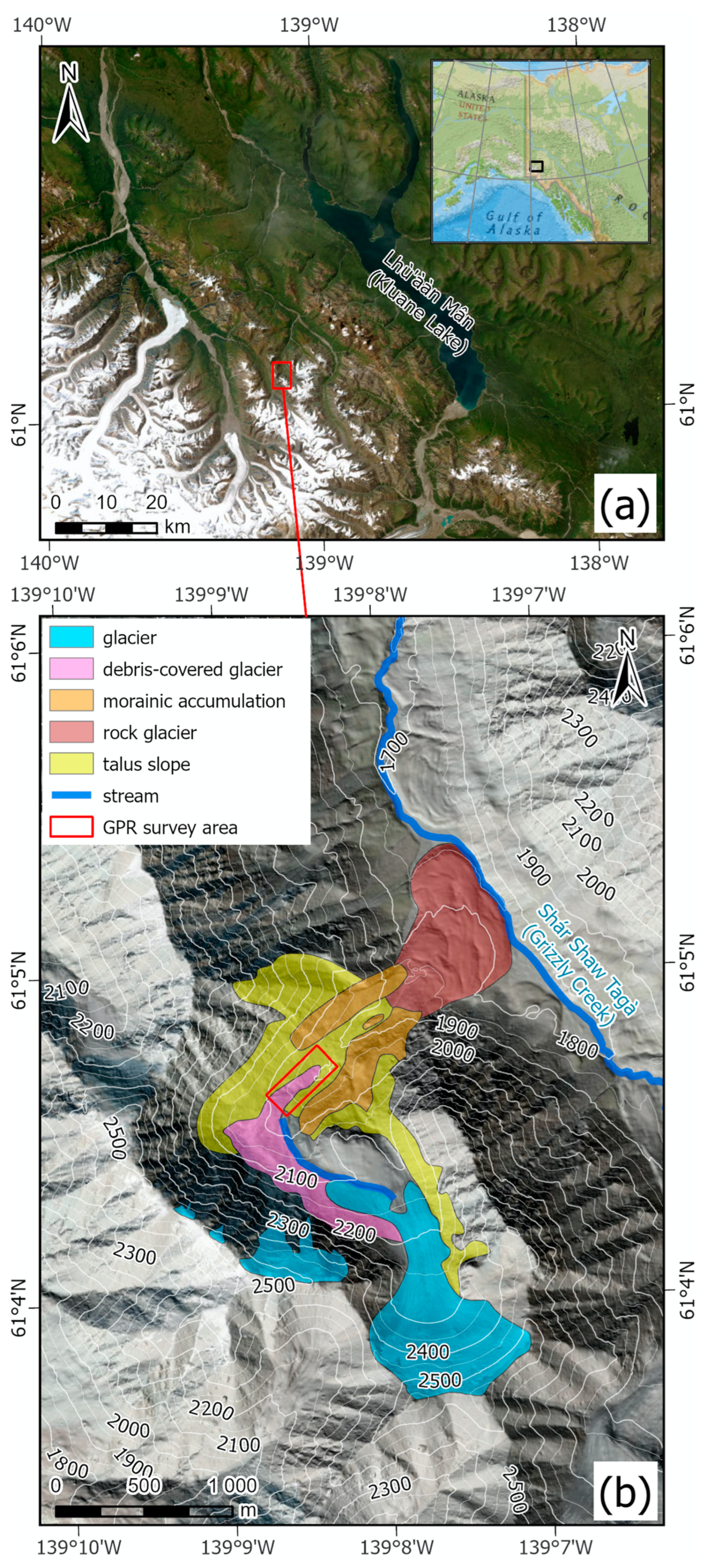
Figure 1. (a) Location of Shár Shaw Tagà (Grizzly Creek) valley within southwestern Yukon, Canada, with the study area identified by a red rectangle. (b) Geomorphological interpretation of the study area. Terrain data are from ArcticDEM by the Polar Geospatial Center under NSF-OPP awards 1043681, 1559691, 1542736, 1810976, and 2129685 [27]. Basemap credits: Esri, Maxar, Earthstar Geographics, National Geographic, and the GIS User Community. Place names are given in Southern Tutchone and English.
Remotesensing 16 02461 g001
Figure 2. Map showing the location of the drone-based, manual, and CMP transects within the study site (b) and larger sub-catchment valley (a).
Remotesensing 16 02461 g002
Figure 3. Processed and annotated radargrams of the (a) 50 MHz, (b) 100 MHz and (c) 200 MHz drone-based GPR transects. Three areas of buried ice, B.I.1, B.I.2 and B.I.3, are outlined for emphasis across the three transect radargrams. Areas of interest at the top of the debris-covered glacier are zoomed in by a factor of 1.5× to emphasize the differing levels of detail of debris thickness, T, discernable across the three antenna frequencies. In (b), h1, h2 and h3 indicate buried ice layer heights, and d1, d2 and d3 show the depths from the surface to the base reflector measured at the locations corresponding to the beginning, middle and end of the CMP and Manual 1 transect. The location of the Manual 2 transect is also indicated in (b).
Remotesensing 16 02461 g003
Figure 4. Manual GPR radargrams from the debris-covered glacier, Manual 2 (ac), and ice–debris complex, Manual 1 (df). In (e) h1, h2 and h3 indicate ice layer height measurements and d1, d2 and d3 show depths measured from the surface to the base reflector.
Remotesensing 16 02461 g004
Figure 5. CMP results showing the trajectory signals of the air wave (yellow), the surface debris/ice interface (red), and the ice/bottom layer (blue) for each of the three antenna frequencies at the CMP 2 (ac) and CMP 1 (df) transects.
Remotesensing 16 02461 g005
Table 1. Results of CMP analysis.
CMP 1CMP 2
50 MHz100 MHz200 MHz50 MHz100 MHz200 MHz
Debris LayerThickness (m)2.93N/A2.61.6N/A
Velocity (cm/ns)13.814.1N/A15.616.7N/A
Permittivity (dim) *4.74.5N/A3.73.3N/A
Ice LayerThickness (m)9.47.6N/A13.69.8N/A
Velocity (cm/ns)14.817.0N/A16.617.8N/A
Permittivity (dim) *4.13.2N/A3.22.9N/A
* Relative permittivity values are reported as dimensionless values, indicated by units of “dim”.
Disclaimer/Publisher’s Note: The statements, opinions and data contained in all publications are solely those of the individual author(s) and contributor(s) and not of MDPI and/or the editor(s). MDPI and/or the editor(s) disclaim responsibility for any injury to people or property resulting from any ideas, methods, instructions or products referred to in the content.