1. Introduction
With the rapid development of software and hardware technologies, the operational modes of radars in electronic warfare (EW) [
1,
2] have evolved from the combination of independent devices to modular and integrated systems [
3,
4]. Scholars have shown a growing interest in the integrated detection and jamming system [
5], whose signal can eliminate typical radar signal characteristics, enhancing detection concealment [
6]. Simultaneously, the sharing of resources between detection and jamming contributes to the overall efficiency of system resource utilization. However, a critical issue persists within the integrated detection and jamming system: strong co-frequency direct wave interference degrades the detection performance [
7]. Traditional radar signal processing methods are unable to address this issue effectively. Current studies on integrated detection and jamming predominantly focus on the design of multifunctional integrated waveforms [
8], with limited exploration of waveform optimization processes like interference suppression [
9,
10,
11]. This paper aims to address this gap by proposing a novel co-frequency direct wave interference suppression method for integrated detection and jamming signal processing.
The most typical waveform among radar transmission signals is the linear frequency modulation (LFM) [
12] signal. In waveform design, operations like convolution and modulation applied to the LFM signal could result in the generation of integrated detection and jamming signals [
13]. An example of such a signal is the minimum shift keying-linear frequency modulation (MSK-LFM) signal [
14]. Additionally, some scholars have proposed a cooperative detection and localization technique based on noise frequency modulation (NFM) jamming signals [
5,
15], which could be utilized to design integrated detection and interference signals waveforms. From a resource perspective, orthogonal LFM multiplexing synthetic waveforms [
16] can also function as integrated waveforms. They demonstrate high-resolution target detection performance under appropriate signal-processing protocols [
17]. Although there are many existing integrated waveform design methods, further waveform optimization is required to achieve detection functionality, particularly in the presence of strong co-frequency direct wave interference. At present, there are relatively few effective optimization methods available to tackle this challenge.
In an integrated radar and communication system, diverse digital self-interference cancellation methods [
18,
19] can be employed to tackle the problem of co-frequency self-interference. In the integrated detection and jamming system, the detected target echoes will include the adversary transmission signal that shares the same frequency band. Traditional radar signal processing methods, such as matched filtering (MF) [
20], are unable to address this issue.Ref. [
21] proposed a receiving and processing method based on prior information to identify and suppress adversary LFM signals from the time-domain pulses of signal echoes. Transforming the echoes of the integrated signal into the fractional Fourier (FRFT) [
22,
23] domain is also effective in identifying and suppressing LFM direct wave interference [
24]. Building on this approach, we previously proposed a de-slope filtering and sparse recovery method [
25]. The adversary’s LFM slope can be estimated using FRFT, and the adversary signals can then be filtered through frequency filtering. In cases where the interference energy is exceptionally strong and results in the loss of useful integrated signals, further restoration can be achieved through sparse recovery [
26] based on the smoothed-
(SL0) algorithm [
27]. For interference with moderate intensity, employing time-varying filtering (TVF) [
28,
29,
30] in the echo domain can yield favorable outcomes. However, these methods do not fully exploit the known prior information and solely process each pulse repetition interval (PRI) from the time dimension. The optimization problem only incorporates the sparsity of the range dimension as a constraint during solving. Detecting targets becomes challenging when facing strong co-frequency direct wave interference.
In this paper, a new co-frequency direct wave interference suppression method is proposed for integrated detection and jamming signal processing. In contrast to the traditional approach of processing signals for each PRI separately, the proposed method directly processes the entire echo matrix based on the sparsity of the range-Doppler domain. Initially, we leverage prior information to design a joint delay dictionary incorporating both our integrated signals and adversary signals. Combining the joint delay dictionary with the Doppler dictionary allows us to construct a signal model that correlates with both the echo matrix and the range-Doppler matrix. Subsequently, we derive the 2D sparse recovery optimization problem [
31] for interference suppression. Utilizing the two-dimensional sparsity of targets, we solve the 2D sparse recovery problem employing the 2D generalized smoothed-
(2DGSL0) algorithm [
32,
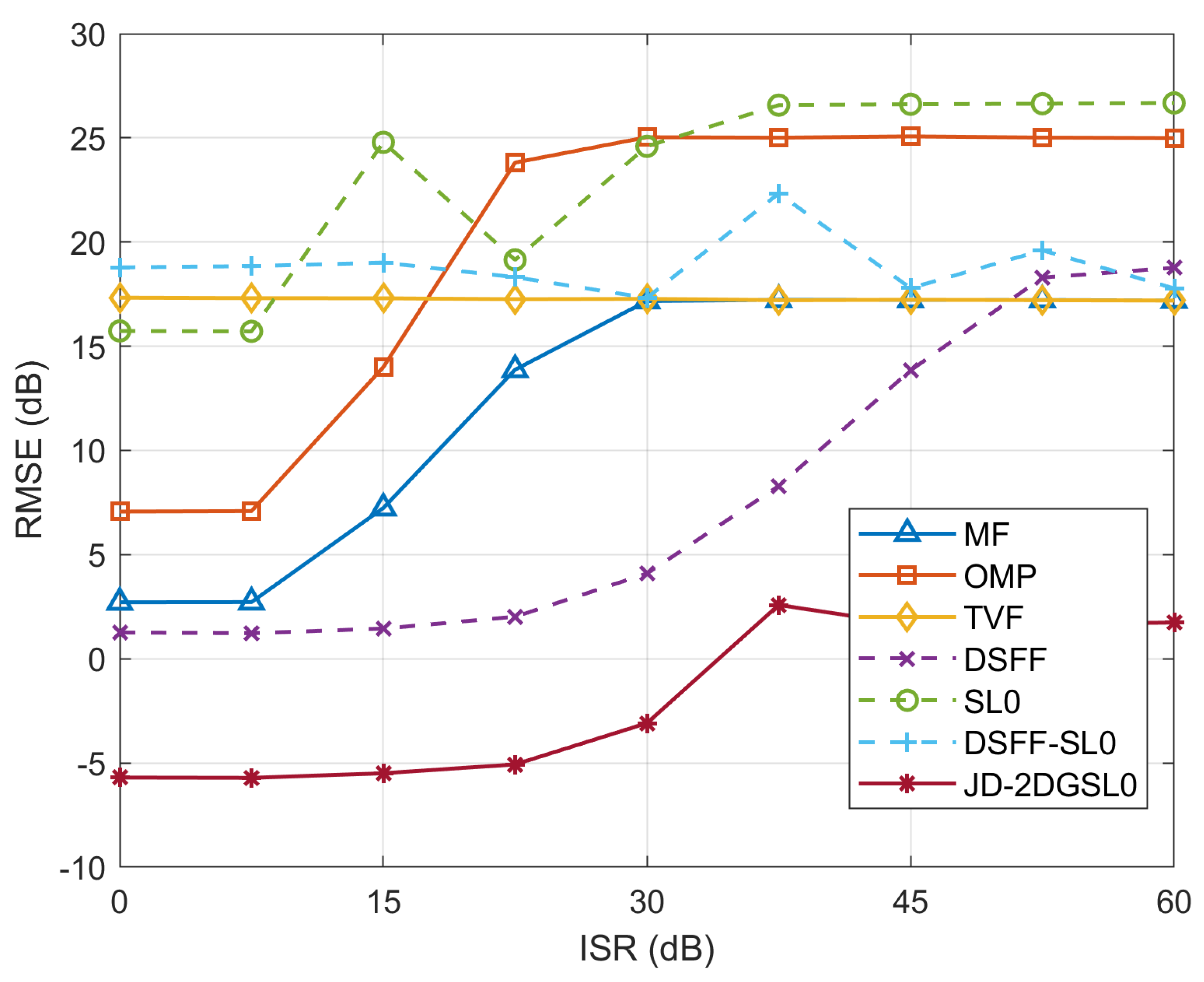
33], directly yielding the range-Doppler map results. Additionally, manually adjusting algorithm parameters such as iteration step size and threshold according to different situations, along with an adaptive regularization parameter, can enhance the algorithm’s robustness to varying interference intensities. Different from traditional approaches, the proposed method leverages prior information and directly processes the entire echo matrix based on the sparsity of the range-Doppler domain. This approach demonstrates superior sparse recovery performance compared to existing methods, and can further suppress range sidelobes and mitigate the effects of strong co-frequency direct wave interference.
The contributions of this article can be outlined as follows: (1) proposing a novel method to suppress co-frequency direct wave interference, addressing a significant problem within the integrated detection and jamming system. (2) exploiting prior information to construct the joint delay dictionary and establishing the 2D received integrated signal model along with the sparse recovery optimization problem based on the 2D generalized smoothed- (2DGSL0) algorithm. (3) utilizing simulation and experimentation to explore the integrated detection and jamming working scenarios and verify the feasibility of the algorithm.
This paper is organized as follows.
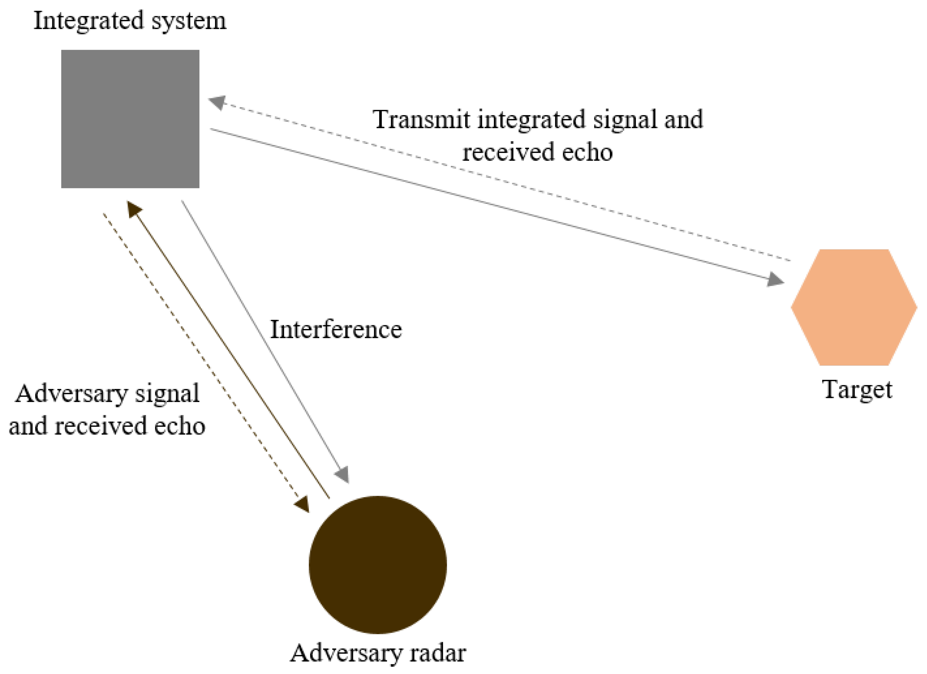
Section 2 discusses the working scenario and the receiving signal model of the detection and jamming integrated system.
Section 3 presents the limitations of the one-dimensional traditional approach that we have proposed in the past. The joint dictionary signal model and two-dimensional sparse recovery based on the 2D generalized smoothed-
(2DGSL0) algorithm are introduced in
Section 4. Simulation and experimental results to verify the superior performance of the proposed method are demonstrated in
Section 5 and
Section 6. Finally,
Section 7 summarizes this paper and discusses limitations and prospects.
3. Traditional Methodology
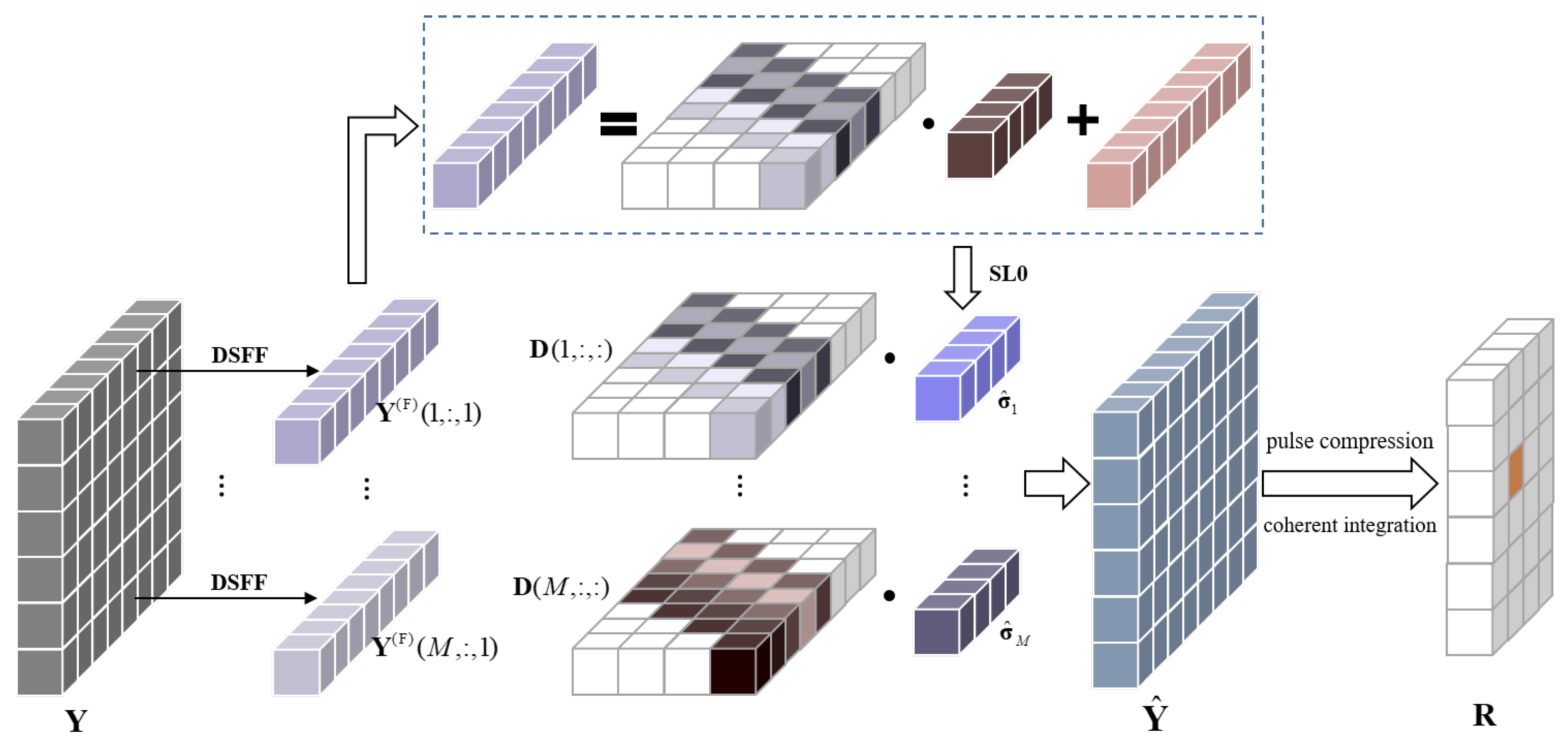
To suppress co-frequency interference caused by direct waves emitted by adversary radar during integrated system detection, we have proposed a De-slope filtering and sparse recovery method in the past [
25]. The De-slope frequency domain filtering (DSFF) processing was applied for each PRI, followed by sparse recovery based on the smoothed-
(SL0) algorithm. This step aimed to further reconstruct the pure integrated signal echo and compensate for the useful signal part lost during filtering. After processing by the De-slope frequency domain filtering and smoothed-
based sparse recovery (DSFF-SL0) method, matched filtering can be applied to conduct pulse compression for each PRI. Subsequently, coherent integration among different PRIs can yield results of range-Doppler maps. The schematic diagram of the traditional DSFF-SLO method is shown in
Figure 4.
Due to the continuous linear frequency variation of the LFM signal, the Fractional Fourier Transform (FRFT) can be used for the detection and parameter estimation [
35,
36] of the LFM signal. After obtaining the frequency modulation slope of the LFM signal, the slope removal method [
37] is applied to convert the LFM signal into a manageable single-frequency signal. Finally, the frequency domain filtering method is used to suppress the influence of the LFM signal on the target signal.
The
mth PRI echo is
and then the FRFT of signal
is defined as follows:
where
is the order of the FRFT, which can be any real number, and
.
represents the FRFT operator symbol, and
is the FRFT kernel.
When the adversary radar transmits an LFM signal, the direct wave signal received by our integrated system can be expressed as:
where
represents the matrix envelope.
is the starting frequency.
is the signal amplitude and
is the pulse width.
k is the frequency modulation slope.
represents the time delay of the direct wave from the adversary radar to our integrated system.
Due to the different energy concentrations of the LFM signal in different FRFT domains. We can estimate the slope of the adversary signal and remove it to obtain the de-sloped signal
[
25]. Further through frequency domain filtering and inverse de-sloping operations
, the final purified result of our integrated system echo after removing the LFM direct wave interference is obtained as:
where
and
are the NFM integrated signal echo and the LFM direct wave signal respectively after the DSFF processing.
In situations with strong interference energy, the DSFF method might not completely mitigate the impact of co-frequency interference and could lose certain useful signal echoes. To extract the pure integrated signal echoes, further processing can be performed using sparse recovery methods.
Unfortunately, the output signal after the de-slope filtering will no longer be represented in the dictionary . As part of the echo containing the information from our transmitted integrated signal is lost and cannot be expressed as a linear combination of delayed transmitted pulses. For each echo pulse contaminated by the adversary signals, the dictionary must be constructed based on the characteristics of the signal after DSFF processing.
According to Equation (14), the
mth PRI signal echo can be expressed in another form based on the linear characteristics of the DSFF processing:
Combining with Equation (10),
can be written as:
where
represents the
ith row of the sub-dictionary
,
is the
ith element of the vector
.
is the adaptive dictionary for the current echo pulse. In practical implementation, the processing results for other atoms can be represented as time-shifted forms of corresponding atoms, allowing the storage of DSFF results for specific atoms in memory to reduce computational complexity. Based on Equations (16) and (15) can be written as:
where
represents the residual equivalent noise composed of the direct adversary signal after the DSFF processing and additive noise:
By further transforming this problem into an optimization problem, and using the
and
norms to enforce sparsity constraints [
38], we can obtain the sparse coefficients
to solve the following sparse decomposition denoising problem [
39]:
where
denotes the residual errors which represent the one-dimensional sparsity level of the scene. The sparse recovery model of this type of one-dimensional vector can be solved by smoothed-
(SL0) algorithm [
27] or orthogonal matching pursuit (OMP) [
40,
41].
Assuming
is the solution to the optimization problem in Equation (19), the extracted
mth PRI pure integrated signal echo
can be represented as:
Subsequently, processing the signal of each PRI through the DSFF-SL0 method enables the suppression of co-frequency interference across all pulses. Following this preprocessing step, matched filtering can be employed for pulse compression in each PRI, and coherent integration across different PRIs can be conducted to obtain the range-Doppler map result.
Since our integrated signal is constructed based on intercepted adversary signal parameters, the known prior information is not fully utilized during the dictionary construction. Additionally, this method employs de-sloping filtering and one-dimensional sparse recovery for each PRI, utilizing only the sparsity of the range dimension as a constraint during solving. In situations with strong co-frequency direct wave interference, it has difficulty effectively suppressing the interference background in the detection results.
4. Co-Frequency Interference Suppression Based on Joint Dictionary and 2D Sparse Recovery
In this section, we propose a method for suppressing co-frequency direct wave interference. This method involves constructing a signal model using a joint dictionary and performing sparse recovery based on the 2D generalized smoothed-
(2DGSL0) algorithm [
31,
33]. No longer is the signal processing performed on each PRI individually, instead, the entire echo matrix is directly processed based on the sparsity in the two-dimensional domain of range and Doppler. By utilizing a joint delay dictionary derived from the transmitted signal of both parties and a Doppler dictionary, the sparse decomposition problem is solved directly to obtain the range-Doppler map results. This method demonstrates superior sparse recovery performance in comparison to the one-dimensional approach across PRI. It enables more effective suppression of range sidelobes and mitigates the impact of strong co-frequency direct wave interference, thereby enhancing the target detection capability of the integrated signal.
The schematic diagram of the joint dictionary integrated signal echo model is shown in
Figure 5.
4.1. Jiont Dictionary Signal Model
According to the signal model (7) in section II. The echo received by our integrated system can be expressed as
Similar to the integrated signal echo matrix
, the adversary radar’s co-frequency direct wave matrix
can also be represented by the delay and Doppler dictionaries, that is
where the matrix
is the delay sub-dictionary for the adversary transmitted signal in
mth PRI. Let
be the signal transmitted by adversary radar, the
column
can be represented as
where
represents the resolution of the delay sub-dictionary. The matrix
is the range-Doppler map obtained through the processing of the transmitted signal of the adversary radar. After combining the range-Doppler map of our signal and the adversary direct wave, it can be represented by a joint delay dictionary. Then the total echo can be expressed as
where the matrix
denotes the joint delay dictionary. The
mth PRI subdictionary
can be represented as
The joint range-Doppler map
. The direct wave signal emitted by the adversary radar does not contain target information, so the range-Doppler map
has weak sparseness. However, the targets’ range-Doppler map
through processing the integrated signal is sparse. Therefore, as a combination of a sparse matrix and a non-sparse matrix, the joint range-Doppler map
still has a certain degree of sparseness. To capture the 2D sparsity of matrix
, the cost function can be defined as
where the indicator function
is
Subsequently, the joint range-Doppler map
can be reconstructed through solving the 2D sparse recovery optimization problem:
4.2. Sparse Recovery Based on 2D Generalized Smoothed- (2DGSL0) Algorithm
To solve the sparse decomposition optimization problem (28), we use the JD-2DGSL0 method [
31] based on the joint dictionary signal model (24) and the 2D generalized smoothed-
algorithm [
33]. Considering that the
norm of a matrix is a discontinuous indicator function, which is highly sensitive to noise during the search [
27]. Thus, a continuous cost function is established to approximate the discontinuous indicator function in this context. Contemplate a Gaussian function:
Subsequently, the indicator function can be approximated by
For ease of expression, we construct a functional expression:
Then, the continuous smoothed-
cost function
to approximate the discontinuous
norm can be represented as
Although the minimization of
is equivalent to the minimization of
when
is small, at this point,
contains many local minima. On the flip side,
becomes smoother with the increase of
. To prevent falling into local minima, we can address the optimization problem through iterations, gradually decreasing the value of
. Further considering that each pulse of the integrated waveform is different, the problem model (28) can be expressed as
where
denotes the joint range profile matrix. The
is minimized through gradient descent steps under the constraints of the
to enhance sparsity and the projection steps to improve accuracy. During the gradient descend step, we seek a matrix
that minimizes
by
where
represents the step size and
is the gradient of
. The element at the index
in
can be represented as
In the projection step, the matrix
, which has undergone sparse optimization, needs to be projected into the feasible set to guarantee the accuracy of recovery. Sparse recovery within each PRI pulse can be achieved by a range profile projection, while 2D accuracy is ensured by a 2D range-Doppler map projection. The
mth PRI range profile projection can be viewed as an optimization problem:
where
is the range profile matrix corresponding to the optimized
in the gradient descend step.
is an adaptive regularization parameter employed to maintain an acceptable recovery accuracy level, and the resulting solution closely aligns with that obtained through the steepest descent step. The application of this regularization term markedly improves the algorithm’s robustness to interference intensity and noise [
42]. We write Equation (36) as
. Therefore, to obtain this minimum value, the derivative of
is derived in
.
Let
, the optimization problem (36) has an analytical solution:
where
represents the matrix inversion operator. After the projection of the range profile, the joint range-Doppler map projection [
33] can be obtained by solving:
Then we can obtain the pure integrated signal’s range-Doppler map . The whole steps of the proposed JD-2DGSL0 method are shown in Algorithm 1.
To facilitate the algorithm’s rapid convergence towards an initial solution close to the actual minimizer, an initial configuration is set with a sufficiently large value of
, which is gradually decreased during iterations. The gradual reduction of
is implemented to approach the actual minimum sparse solution, preventing the algorithm from becoming trapped in local minima. This ensures accuracy in sparse recovery in the range-Doppler domain.
| Algorithm 1 Joint Dictionary and 2D Generalized Smoothed- Algorithm (JD-2DGSL0) |
Input: Received echo ; Doppler dictionary ; Joint delay dictionary ; Output: Range-Doppler map ; 1: Set the step-size parameter: 2: Set a sequence with decreasing values: 3: Initialize : 4: Initialize : 5: for do 6: 7: 8: for do 9: Calculate by (35) 10: 11: 12: Calculate by (38) 13: 14: end for 15: 16: end for 17:
|
4.3. Discussion on the Selection of Regularization Parameter
The performance of the proposed JD-2DGSL0 method is closely related to the selection of regularization parameter
. It can be seen from (36) that the approximate solution
obtained by the steepest descent step and the approximate solution fitted to the received data
in the optimizer can be balanced by
. The steepest descent step is intended to produce a sparse solution, so the choice of
is a trade-off between data fidelity and sparsity. Due to the varying proportions of sparsity and residual in different steps of the algorithm [
42], we design an adaptive regularization parameter updating method to achieve a balance during the iteration. An optimized
should satisfy the equation that
, and according to the Equation (37) we have
From the previous analysis, we know that the solver of this equation is
. Then (40) can be expressed as
Taking the Frobenius norm on both sides of the equation, then
can be written as:
Since the
of the current iteration loop step is unknown, we substitute it with the known optimizer solution of the previous inner loop, which is
, then
can be estimated by:
4.4. Complexity Analysis
In this section, we analyze the computational complexity of the proposed method. As demonstrated in Algorithm 1, the main complexity lies in the update of and . Updating requires the calculation of and . The complexity of them are and respectively, and the multiplication of them with a total complexity of . The complexity to update is . Therefore, the complexity at each iteration step is approximately . Suppose the numbers of external and internal loops are and respectively, we can obtain the total complexity of the proposed method is . The complexity of the traditional method DSFF-SLO is . Compared with the traditional method, the proposed method has slightly more computational complexity due to the consideration of the joint dictionary and Doppler characteristics. Fortunately the Doppler dictionary is known a prior and remains unchanged, the term in can be computed off-line in advance and then be cached in the iterations. The term can also be computed off-line, since our transmit integrated waveforms and the intercepted adversary waveforms are known in advance. With these techniques to accelerate the proposed method, the complexity can be reduced to .
6. Experimental Results
In this section, we use real measured data to demonstrate the performance of the proposed method. Following the work scenario described in the section II, we set up an experimental validation system as illustrated in
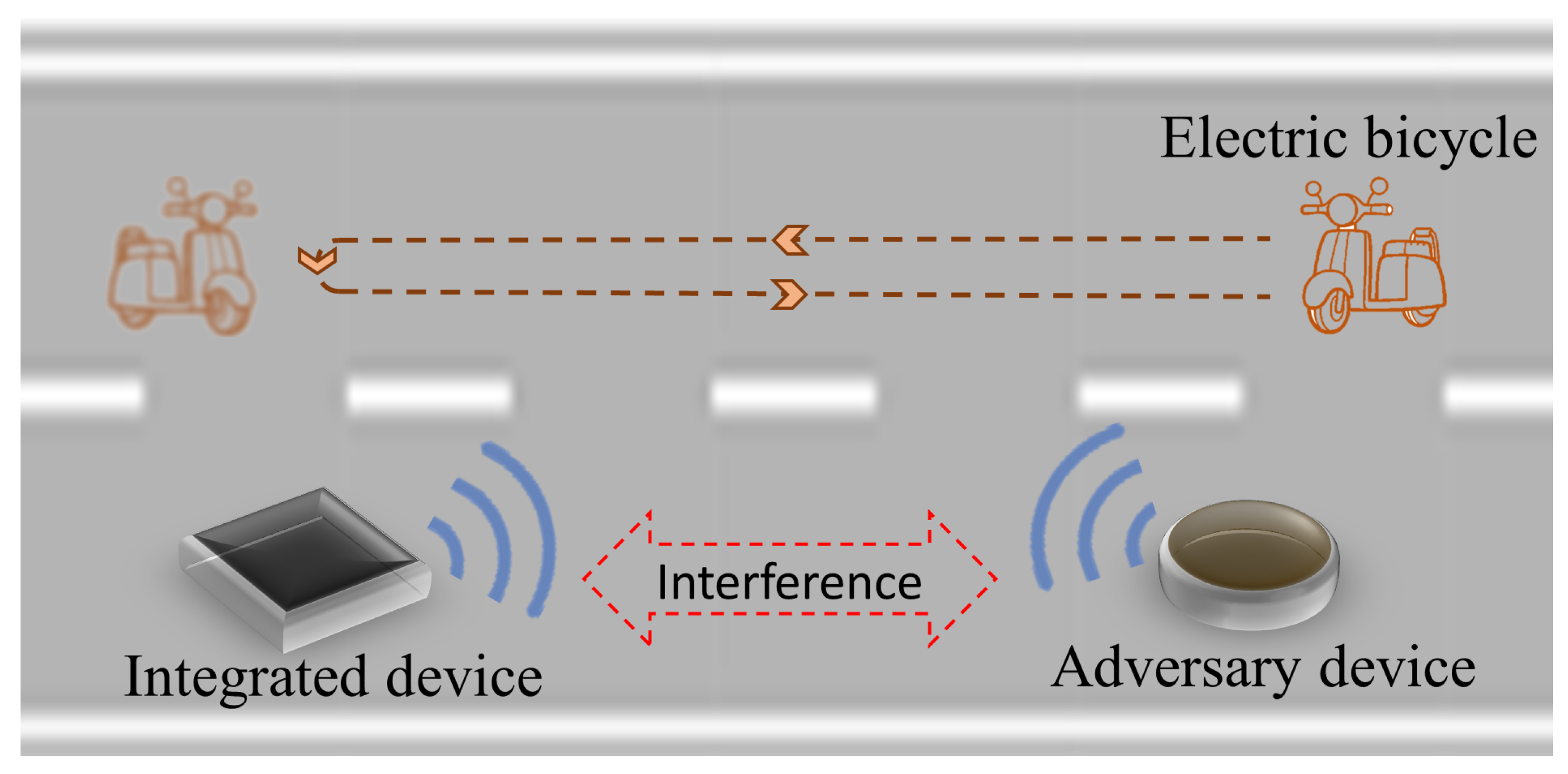
Figure 13. The experimental system consists of a set of adversary radar equipment and a set of our integrated system. Both the adversary and our equipment are located within the beam range of each other’s transmitting and receiving antennas. During the detection process, the transmitted signals from each side interfere with the equipment on the other side. In the experiment, we used an electric bicycle as the moving target to be detected. When the bicycle moved into the beam range of the equipment’s transmitting antenna, both sides’ equipment could detect it. The adversary radar employed an LFM signal for detection. Based on the parameters of the adversary radar’s LFM signal, our integrated system transmits an NFM integrated signal within the same frequency range. The pulse width and bandwidth of the NFM integrated signal are the same as the adversary signal, achieving target detection while simultaneously interfering with the adversary radar. The specific signal parameters and target motion parameters in the experiment are provided in
Table 2. The sampling frequency used for analog-to-digital conversion in signal generation and echo processing is 40 MHz.
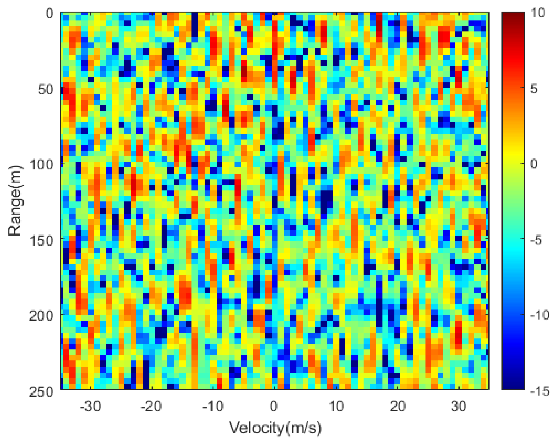
The adversary radar system employs the fundamental MF method for processing the received signal and generating range-Doppler maps. The result under the interference of our transmitted integrated signal is shown in
Figure 14. Our integrated signal achieved a significant interference suppression effect, with real targets in the adversary equipment’s detection results being submerged within our interference.
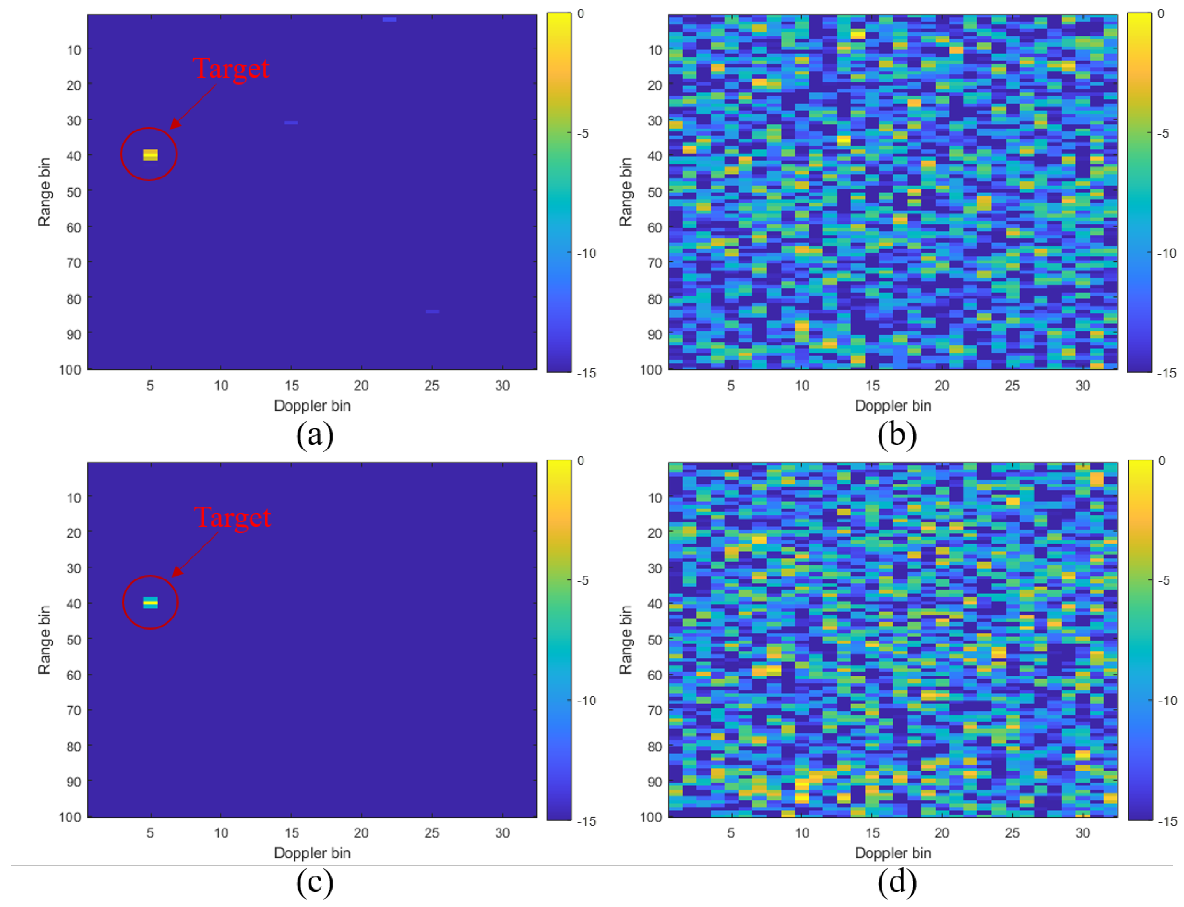
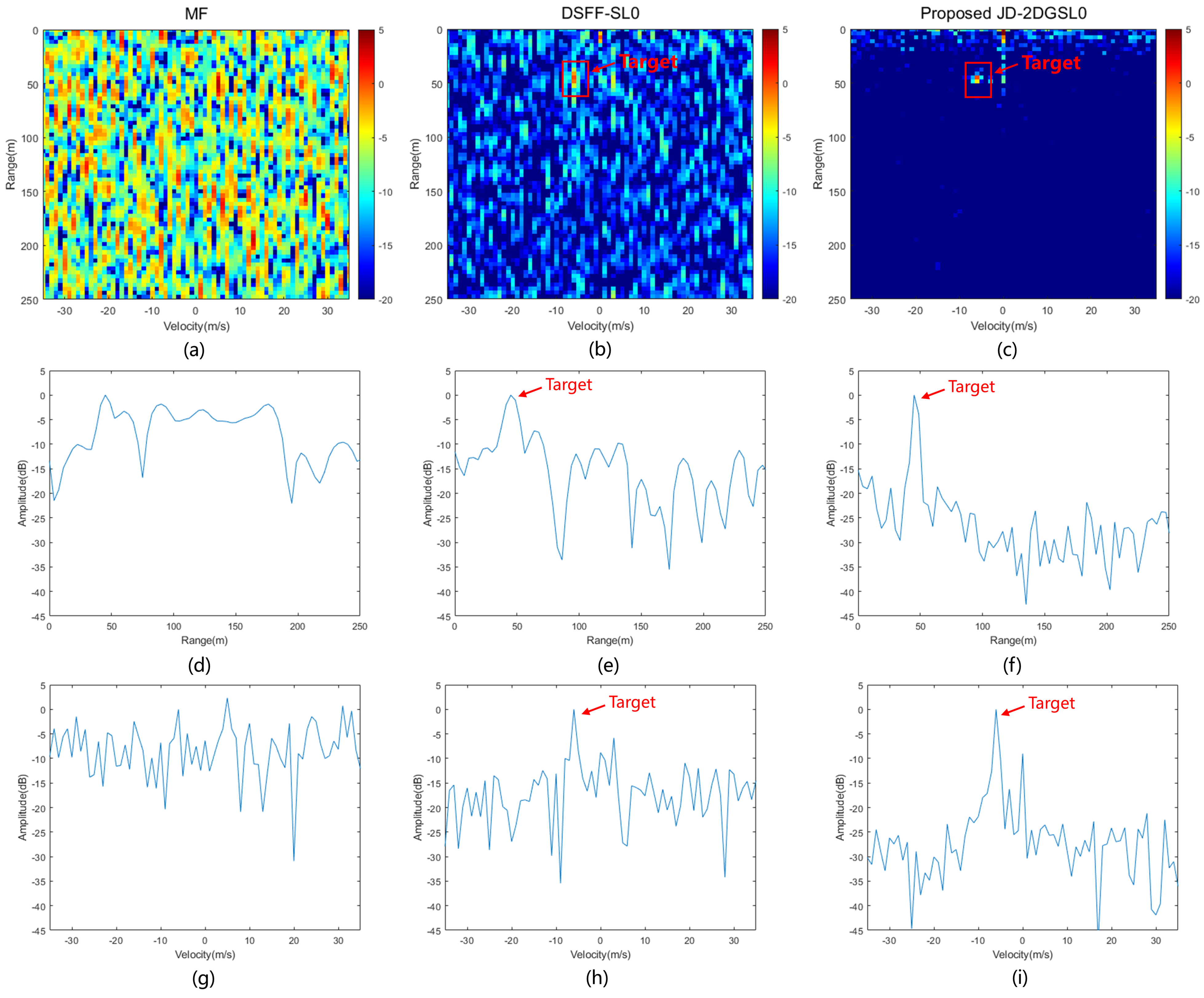
The signal received by our integrated system is processed by the basic MF method, the DSFF-SL0 method, and the proposed JD-2DGSL0 method, respectively. From
Figure 15a, it is evident that our integrated system, when exposed to interference from the adversary radar’s co-frequency direct waves, fails to suppress the interference adequately for target detection through the basic matched filtering method. The range-Doppler maps obtained after processing with the DSFF-SL0 method and the proposed JD-2DGSL0 method are shown in
Figure 15b,c, the interference can be successfully suppressed. However, it is worth noting that the DSFF-SL0 method still retains significant interference, which can impact the detection performance. Further analysis of the imaging results in the range and velocity dimensions for the target cells is presented. The results of the target’s main-to-sidelobe ratios under different processing methods are shown in
Table 3. It can be observed in the presence of interference from the adversary direct wave, the basic matched filtering method exhibits significantly low main-to-sidelobe ratios, making it incapable of accurately extracting the target range and velocity information [see
Figure 15d,g]. After processing with the DSFF-SL0 method, the main-to-sidelobe ratio in the range dimension increased by 6.86 dB, and the velocity dimension increased by 8.63 dB. However, there remains a significant amount of relatively high sidelobes, which can be seen in
Figure 15e,h. After applying the proposed JD-2DGSL0 method, there is a significant improvement in the main-to-sidelobe ratios, with an increase of 21.44 dB in the range dimension and 20.51 dB in the velocity dimension. As a result, the high sidelobe interference is effectively suppressed, allowing for the accurate retrieval of target range and velocity information.
7. Discussion
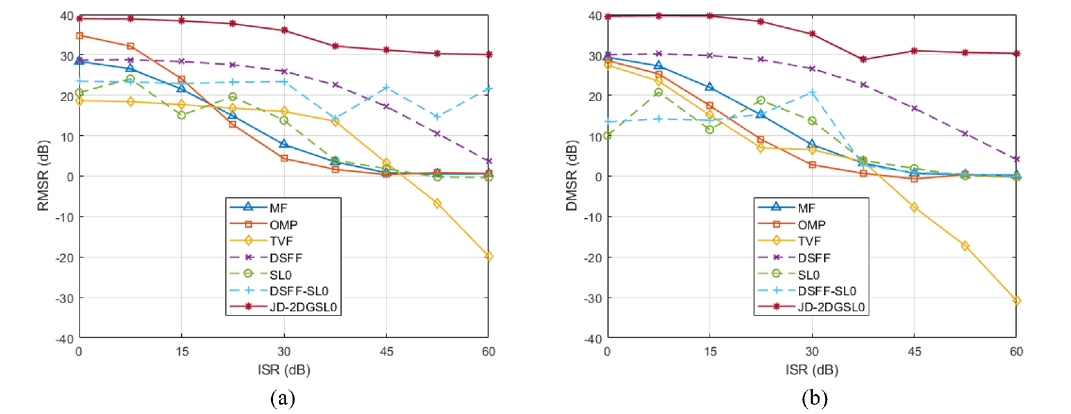
This paper addresses the co-frequency direct wave interference problem in integrated detection and jamming systems. A 2D generalized smoothed- norm based sparse recovery method is proposed to process the received integrated signal echos. We utilize prior information to construct a joint delay dictionary comprising our integrated signals and adversary radar signals. Leveraging the two-dimensional sparse characteristics of the targets, we formulate a sparse recovery optimization problem. The solution to this problem is directly derived from the entire echo matrix, resulting in the 2D range-Doppler map results. Taking the example of the typical LFM radar signal emitted by the adversary radar, our integrated system constructs an NFM integrated signal with the same waveform parameters and transmits it in the same frequency band. The proposed method effectively suppresses the co-frequency direct wave interference caused by the adversary transmission signal, ensuring that our integrated signal maintains excellent target detection performance while interfering with the adversary radar. Benefiting from the introduction of regularization parameters, the proposed method exhibits robustness to varying intensities of co-frequency direct wave interference. Both the target side-lobe levels and the errors in the ideal range-Doppler map are superior compared to traditional radar signal processing methods and the DSFF-SL0 method that we proposed in the past. Simulation and experimental results verify the superior performance of the proposed method.
The interference suppression method proposed in this paper still has some limitations. To simultaneously achieve detection and interference functions, there will inevitably be a certain degree of correlation between our integrated waveform and the adversary radar signal. Although constructing a joint dictionary significantly reduces the impact of the opposing signal on the transmission signal’s delay dictionary, there may still be some influence. In future research, we will consider methods related to dictionary learning to further minimize this impact. On the other hand, some parameters in the optimization algorithm need to be manually set based on various situations during experiments, which can be time-consuming. To address this parameter tuning process, future work could integrate approaches from the field of deep learning, attempting to learn parameter settings from large datasets to save time on experimental parameter tuning.
