Article

An Improved Propagation Prediction Method of Low-Frequency Skywave Fusing Fine Channel Parameters

1
School of Microelectronics, Tianjin University, Tianjin 300072, China
2
Qingdao Institute for Ocean Technology, Tianjin University, Qingdao 266200, China
3
Shandong Engineering Technology Research Center of Ocean Information Awareness and Transmission, Qingdao 266200, China
4
Wuhan Marine Communication Research Institute, China State Shipbuilding Corporation Limited, Wuhan 430200, China
*
Author to whom correspondence should be addressed.
These authors contributed equally to this work.
Remote Sens. 2024, 16(12), 2241; https://doi.org/10.3390/rs16122241
Submission received: 9 May 2024 / Revised: 9 June 2024 / Accepted: 17 June 2024 / Published: 20 June 2024

Abstract

:
Low-frequency communication constitutes a vital component of essential communication systems, serving a pivotal role in remote radio communication, navigation, timing, and seismic analysis. To enhance the predictive precision of low-frequency skywave propagation and address the demands of engineering applications, we propose a high-precision prediction method based on the ITU-R P.684 wave-hop theory and real-time environmental parameter forecasts. This method features several distinctive attributes. Firstly, it employs real-time ionospheric prediction data instead of relying on long-term ionospheric model predictions. Secondly, it utilizes a detailed map of land–sea surface electrical characteristics, surpassing the simplistic land–sea dichotomy previously employed. Compared with measured data, the findings demonstrate that we attained a reasonable propagation pattern and achieved high-precision field strength predictions. Comparatively, the improved method exhibits an improvement in the time and spatial domains over the ITU-R P.684 standard. Finally, the improved method balances computational efficiency with enhanced prediction accuracy, supporting the advancement of low-frequency communication system design and performance evaluation.

Graphical Abstract

1. Introduction

Low-frequency (LF) communication operates within a frequency band defined by the International Telecommunication Union (ITU), spanning from 30 kHz to 300 kHz, with wavelengths ranging from 1000 m to 10,000 m [1]. Renowned for its extensive coverage; capability of spanning tens of thousands of kilometers; and remarkable penetration through various media like rocks, soil, and seawater, LF communication serves as a vital tool for command and control communication across vast land areas, including deep bunkers and tunnels. Additionally, LF propagation remains resilient against anthropogenic interference and nuclear detonation, making it important for communications under extreme environmental conditions. To establish and ensure the reliability of LF communication systems, in-depth studies on low-frequency propagation characteristics have always been a theme of the past, present, and future.
In 1925, Appleton proposed the magneto-ionic theory [2], laying the theoretical foundation for the propagation of radio waves in the ionosphere. Subsequently, Booker extended this theory [3], and Bracewell discovered the relationship between ionospheric variations and solar angles [4]. The Cavendish Laboratory conducted significant research on LF propagation. Finally, Budden systematically summarized these findings in his book Radio Waves in the Ionosphere, contributing to the continuous improvement and maturation of LF propagation theory [5]. Based on the work of these pioneers, Wang combined the latest database to analyze in detail four LF skywave propagation prediction methods, comparing them with the measured field strength, and discussed the factors affecting skywave propagation in 1999 [6]. In 2000, Warrington and Jones used the summertime ionospheric model to predict the LF skywave field strength and compared it with the measured field strength to determine the validity of the model [7]. In 2002, Liu et al. calculated and compared the geometric parameters of LF skywave propagation based on the distribution models of different atmospheric refractive indices [8]. In 2004, Wakai used the wave-hop method to predict the field strength of skywaves, ground waves, and synthetic waves within 60 kHz to 500 kHz within 4000 km and then compared it with the measured field strength to verify the effectiveness of the method [9]. In 2006, Wakai used the same method to predict the skywave field strength of 40 kHz and 60 kHz in Japan and compared it with the measured field strength [10]. In 2008, Wang qualitatively and quantitatively discussed the seasonal variation in LF skywave field strength based on a huge LF skywave database [11]. In 2010, Shigeru and Kurihara proposed the development of a receiver system with higher sensitivity and resolution to reduce interference due to the existence of high-order ionospheric reflection mode in LF propagation and multiple noises in long-distance propagation [12]. In 2012, Feng and his team proposed a formula for calculating the reflection coefficient of vertically polarized waves under isotropic conduction conditions based on the oblique reflection propagated by low ionospheric LF propagation, which was well verified [13]. In 2017, Pal et al. qualitatively explained LF propagation anomalies by studying the effect of sudden stratospheric warming events in 2009 on LF signals in the Earth–Ionosphere Waveguide (EIWG) [14]. In the same year, Zhou et al. combined the Finite-Difference Time-Domain (FDTD) method with the Parabolic Equation (PE) method to analyze the propagation characteristics of LF radio waves at short propagation distances with high propagation angles [15]. In 2019, Melchinov predicted relatively accurately the seasonal variation in LF radio waves on the radio propagation path of frozen soil [16]. In 2020, based on the wave-hop theory and FDTD method, Zhou et al. studied the time-delay characteristics of a one-hop skywave in an EIWG within 200 km under different ionospheric conditions and different calculation methods [17]. In 2021, Gasdia and Marshall developed software (released as the LongwaveMode Propagator.jl) similar to the Long Wave Propagation Code (LWPC) but more stable in mode selection than LWPC [18]. In 2022, Mu et al. verified the effects of multiple multi-path delay estimation algorithms in different channel environments and obtained the delay characteristics of LF multi-hop skywaves [19]. In the same year, Zhao et al. combined the atmospheric model with the International Reference Ionosphere (IRI) model and then used the improved FDTD method to analyze the characteristics of LF skywave signals [20]. In 2023, Gao et al. proposed an LF propagation prediction model that considered the geomagnetic effect based on the wave-hop method, which was used to predict the one-hop skywave field strength under different conditions [21].
To address the demands of engineering applications while balancing computational complexity and efficiency and to refine the prediction methods for 40 kHz LF skywave propagation, this study adopts the ITU-R P.684 method (identified as ITU in the following text) as a foundation. Utilizing the Kriging method, we reconstruct real-time data from four ionospheric parameter observation stations and further enhance the electrical characteristic parameters using a global 16-level classification of surface properties. With these inputs, we predict the field strength of 40 kHz signals across a 2000 km range. Subsequently, we conduct spatiotemporal and comprehensive analyses, comparing different methodologies.

2. Method and Improvement

2.1. Method of ITU

Skywave propagation refers to the propagation of radio waves back to the ground receiving point following reflection or refraction through the ionosphere. The amplitude and phase of LF skywaves undergo significant variations during day and night and across seasons. Moreover, they are susceptible to irregular and abnormal changes due to the influence of solar and geophysical events. ITU recommends utilizing the wave-hop method for calculating the field strength of LF skywaves. This method directly addresses the field at the receiving point without delving into the intricacies of the propagation process. In the wave-hop method, the total field strength of the received signal is a synthesis of ground wave field strength and skywave field strength. Particularly in short-range propagation, ground wave propagation exhibits distinct advantages. As the propagation distance increases, the skywave gradually assumes a dominant position. In this paper, the 40 kHz field strength is calculated based on the wave-hop method to validate and improve the LF skywave propagation prediction method. Within 2,000 km, there are four possible modes of skywave propagation. Figure 1a,b both depict one-hop skywave propagation. In (a), radio waves emitted by the transmitter are directly received by the receiver following ionospheric reflection. In (b), radio waves emitted by the transmitter initially diffuse along the ground to point A, then incidentally reach the ionosphere tangentially, reflecting at point P and subsequently reaching point B on the ground tangentially. The waves then continue to diffuse along the ground to the receiver. Figure 1c,d illustrate two-hop skywave propagation. In (c), radio waves emitted by the transmitter are received by the receiver after two ionospheric reflections and one ground reflection. In (d), radio waves emitted by the transmitter initially diffuse along the ground to point A, then incidentally reach the ionosphere tangentially. After two ionospheric reflections and one ground reflection, they reach point B on the ground tangentially and proceed to diffuse along the ground to the receiver. The bold parts in Figure 1b,d show the path where the diffraction occurs.
The field strength E at the receiving point is the synthesis of the field generated by the ground diffraction wave and the field generated by the skywave, that is,
E = E g + m = 1 M E s m ( mV / m )
where Eg is the ground wave field strength [22] and E s m is the effective field strength of the m-hop skywave. For a short vertical dipole antenna, the effective field strength of the m-hop skywave is given in the following:
E s m = 2 V u L ( cos ψ ) 2 n = 1 m R m , n D R g m 1 F t F r ( mV / m )
V u = 300 P t ( V )
where Pt is the radiated power of the transmitter (kW) and L is the skywave path length, which is expressed as follows:
L = 2 m R e sin ( d / m 2 R e ) sec ( ψ + d / m 2 R e ) ( km )
where d is the great circle distance (km) between the transmitter and the receiver, Re is the effective earth radius (km), and ψ is the elevation angle, which is expressed explicitly as follows:
ψ = arctan ( cot ( d / m 2 R e ) R e csc ( d / m 2 R e ) ( R e + h r ) ) ( rad )
where hr is the ionospheric reflection height, which is expressed as follows:
h r = h max y 1 f f b f O E ( km )
y = y ( y y min ) ( f max f O E ) f max f min
y = y max ( y max y min ) ( f 0 f max ) f 0 f min
where f is the frequency (kHz), fb is the fundamental frequency (set at 10 kHz), fOE is the critical frequency of the E layer [23], fmin (the minimum of fOE at a point), fmax (the maximum of fOE at a point), f0 (fOE when the cosine value of the solar zenith angle χ is 0), hmax is the maximum peak height of layer E (set at 100 km), ymin is the minimum half-thickness of layer E (set at 10 km), and ymax is the maximum half-thickness of layer E (set at 30 km).
In Formula (2), D is the ionospheric focusing factor [24], which is expressed as follows:
D = { ( R e + h r R e ) [ 2 sin ( θ 2 m ) sin θ ] 1 2 [ R e + h r R e cos ( θ 2 m ) ( R e + h r ) cos ( θ 2 m ) R e ] 1 2 × R ( ρ ) ψ 2.2204 × 10 16 ( 2 m sin θ c ) 1 2 [ ( R e + h r R e ) 2 1 ] 1 2 × 1.3466 ( k R e 3 ) 1 6 e i π 12 2.2204 × 10 16 ψ > 0 ( 2 m sin θ ) 1 2 { [ ( R e + h r R e ) 2 1 ] 1 2 + θ θ c 2 m } × 1.3466 ( k R e 3 ) 1 6 e i π 12 ψ < 0
where R(ρ) is the correction factor, k is the number of wavelengths (=2π/λ), and θ is the angular distance between the launching points and receiving points; when the wave is tangent to the ground, θ is θc, which can be expressed as follows:
θ c = 2 m arccos ( R e R e + h r ) ( rad )
R ( ρ ) = ( π ρ / 2 ) 1 2 H 1 / 3 ( 1 ) ( ρ ) e i ( 5 π 12 ρ )
where λ is the wavelength (km) and H 1 / 3 ( 1 ) is a Bessel function; ρ is
ρ = ( k R e / 3 ) cos 3 ( π / 2 ψ ) sin 2 ( π / 2 ψ )
where Rm,n is the ionospheric reflection coefficient of the n-th reflection point of the m-hop skywave. It is a function of fcos(i) and cos(χ) and is calculated via interpolation under given conditions [25]. i is the ionospheric incidence angle, which is
i = arcsin ( R e cos ( ψ ) R e + h r ) ( rad )
where Ft and Fr are the antenna factors of the transmitter and receiver, respectively. These factors are derived based on different conductivities σ and dielectric constant ε and then interpolated according to the elevation angle ψ and the frequency f. Rg is the ground reflection coefficient, which is expressed as follows:
R g = { n 2 sin ( ψ ) n 2 cos 2 ( ψ ) n 2 sin ( ψ ) + n 2 cos 2 ( ψ ) ψ > 0 E D / E F ψ 0
where ED is the diffracted field strength, EF is the free-space field strength (which can be calculated with the “LFMF-Smooth Earth (v1.1)” software described in ITU-R P.368), and n is the complex dielectric constant, which is expressed as follows:
n 2 = ε j 18 σ × 10 6 f

2.2. Fine Channel Parameters and Method Improvement

2.2.1. Real-Time Reconstruction of Ionospheric Parameters

The ionosphere serves as the upper boundary of LF skywave propagation. The precision of predicting its reflection height directly influences the accuracy of LF skywave propagation forecasts. In view of the real-time performance of ionospheric detection data, we used the ionospheric reconstruction method to achieve the real-time prediction of ionospheric parameters so as to improve the accuracy of LF skywave propagation prediction. According to the method of ITU, the ionospheric reflection height is related to fOE. By calculating surrounding detection data, the fOE can be reconstructed, enabling the determination of the ionospheric reflection height for LF propagation reflection. Here, we choose the Kriging method for real-time prediction.
The Kriging method is a widely used interpolation algorithm in ionospheric parameter reconstruction, which can provide the best linear unbiased estimation and accurately describe the spatial structure of ionospheric data. It uses known sample values and a variance function describing the spatial correlation of the observed sample (calculated by the difference between two pairs of observations at a given distance) to determine unknown values at different spatial locations [26].
When using the Kriging interpolation method to reconstruct, the procedure involves establishing the variance function to obtain spatial autocorrelation of the variables. Subsequently, statistical correlation between observed values is estimated, and the target position is reconstructed. In ionospheric parameter reconstruction, the Kriging interpolation method is specifically applied using “ionospheric distance” to construct the variance function in the Kriging equations. The reconstructed result of the improved Kriging method is defined as the linear weighting of the known ionospheric fOE values, which can be expressed as follows:
f O E ˜ ( λ , φ ) = i = 1 N w i f O E ( λ i , φ i )
where f O E ˜ ( λ , φ ) is the reconstructed value of fOE at any location, N is the number of observation stations, wi is the weight coefficient of the i-th observation station, fOE(λi, φi) is the observed value of fOE at the i-th station, and λi and φi are the latitude and longitude of the i-th station, respectively.
The weight coefficient is calculated using the Lagrange multiplier algorithm. To ensure the mathematical expectation of the error of the estimated value zero and the sum of squares between the reconstructed value and the observed value minimum, the optimal weight coefficient wi can be obtained from the linear Kriging equation:
{ i = 1 N r i j w i = r j 0 - μ i = 1 , 2 , , N i = 1 N w i = 1
where μ is the Lagrange factor, rij is the “ionospheric distance” between station i and j, rj0 is the “ionospheric distance” between station j and the reconstructed location, and the sum of all weighting coefficients wi is 1 to ensure unbiased results.
The described process outlines the reconstruction process of the ionospheric parameter fOE. The core is to use the variance function established through “ionospheric distance” to identify spatial correlation, determine the weight coefficient for each station, and finally obtain the reconstructed value for the target position through the linear combination of the known observed value and the obtained weight coefficients. The variation function of ionospheric distance directly influences the reliability of fOE reconstruction. This paper adopts the modified Euclidean distance with a scale factor under standard geographic coordinates [27], expressed as follows:
r i j = ( φ i φ j ) 2 + ( s ( λ i λ j ) ) 2
where s is the scale factor.
In summary, the specific implementation process of the fOE reconstruction method is as follows: based on the determined ionospheric distance calculation method, the semi-variance function of the ionospheric distance between observation stations is estimated.
R = [ 0 r 12 r 1 N r 21 0 r 2 N r N 1 r N 2 0 ]
Simultaneously, the ionospheric distance vector between the unknown location (λ, φ) and the known observation station (λ0, φ0) is calculated. This calculation includes the estimation of the semi-variance function R0, namely:
R 0 = [ r 10 r 20 r N 0 ] T
where T represents the transpose of the matrix. Formula (17) is used to calculate the weight W, which is expressed through vector representation:
W = [ w 1 w 2 w N ] T
The fOE for any location is calculated using Formula (16).
Based on this, the ionospheric reflection height of the corresponding region can be obtained using Formulas (6)–(8). In East Asia, for example, observational data from four stations, Kokubunji, Okinawa, Wakkanai, and Yamagawa (in Figure 2), are used. The variation pattern of ionospheric reflection height hr at 12 Japan Standard Time (JST) and the corresponding fOE of different methods can be compared. As shown in Figure 3, the region colors from dark to light represent hr and fOE from low to high. It can be seen that the distribution of fOE and hr calculated based on the ITU method shows a trend of north–south change (in (a) and (b)). The fOE and hr distribution were calculated using the measured data of the four stations, and the Kriging method shows a trend of change from northeast to southwest (in (c) and (e)). Accordingly, the different distributions of the two show a changing trend from northwest to southeast. At least in East Asia, the distribution presented by the method based on measured data in this paper is closer to the real situation than that offered using the ITU method [28].

2.2.2. Refined Land–Sea Surface Electrical Characteristics

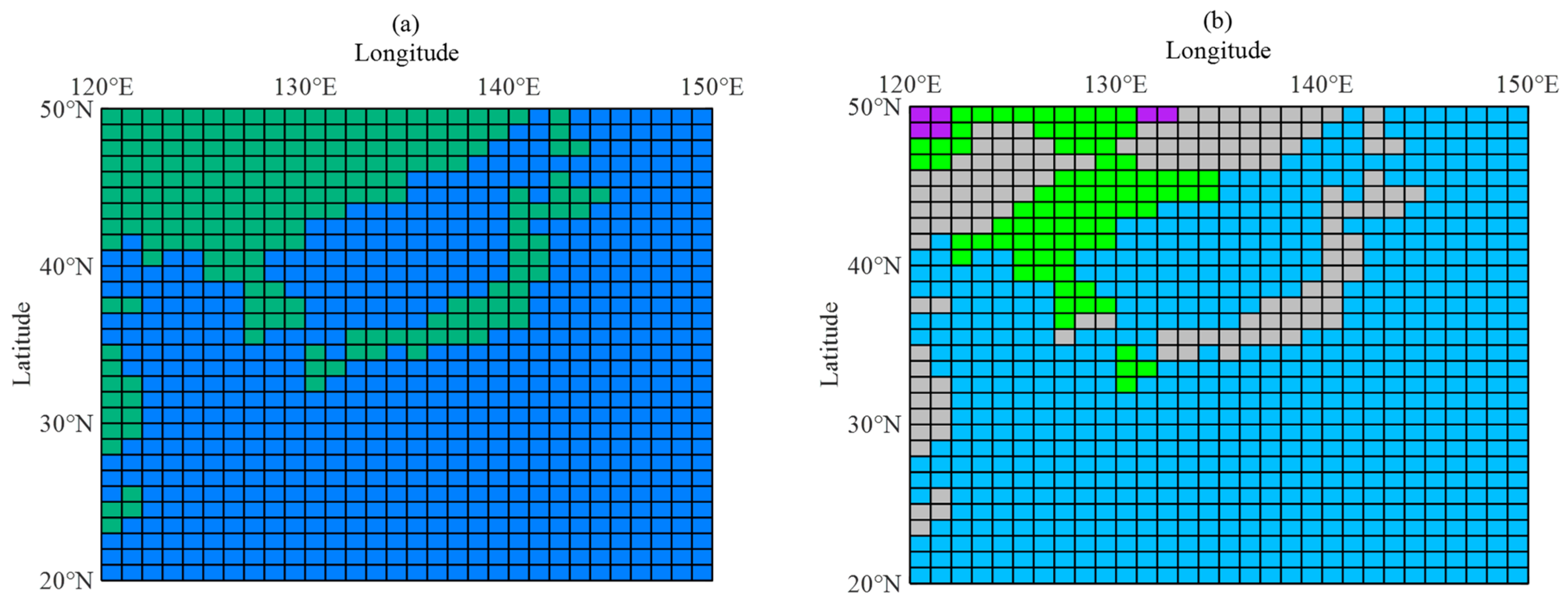
As depicted in Figure 4a,b, the blue squares denote sea areas, while the other colored squares represent land areas. Various colors signify different classifications of electrical characteristics, detailed in Table 1. For example, blue squares indicate a permittivity of 80 F/m and a conductivity of 5 S/m for corresponding sea areas. Figure 4a shows that, according to the ITU method, only blue and dark green areas are distinguished in East Asia due to their simplistic and rather coarse land–sea classification. To enhance prediction accuracy, we adopt a global distribution of 16-level land–sea surface electrical characteristics. This provides a more detailed division of land types, such as dry land and wetland, whose electrical characteristics vary and do not align with the ITU’s assumptions. As depicted in Figure 4b, the improved method reveals “Light Blue, Green, Grey, and Purple” areas in East Asia, each representing distinct electrical characteristics. This results in a more detailed classification compared to the ITU method. For example, the electrical characteristics of Japan’s main islands undergo changes following the improvement.

3. Analysis

3.1. Data Acquisition

In this research, we acquired the 40 kHz measurement data published by the ITU and referred to the radio wave transmitter specifications in Table 2. The transmitter position was set at (37.4°N, 140.8°E), and field measurements were conducted in November 2013 using a ship equipped with a receiver. The receiver fitted with a short vertical dipole antenna performed LF propagation data acquisition every hour. Finally, a total of 78 point-to-point link measurements from 55 receiver position points within a range of 2000 km were obtained.

3.2. Analysis of Improved Method

According to the improved method proposed in this paper, the variation in propagation parameters is compared before and after applying the improved prediction method for the mentioned stations and their surrounding areas.
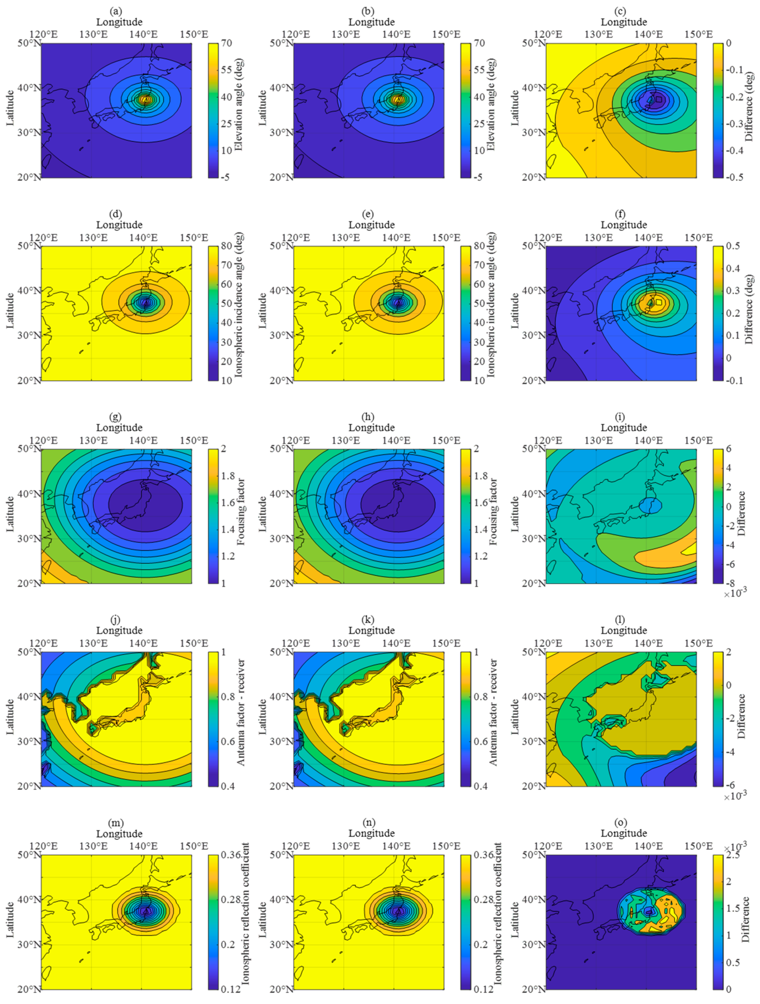
In Figure 5, the first line shows the variation in ψ, the second line shows the variation in i, the third line shows the variation in D, the fourth line shows the variation in Fr, and the fifth line shows the variation in R. In each line, the first column shows the parameter variation of the ITU method, the second column shows the parameter variation of the improved method (identified as the PRO method), and the third column shows the difference between ITU and PRO. The region’s color from light to dark shows the parameter values from high to low.
As observed in Figure 5, the introduction of the fine-channel parameter correction method exhibits noticeable differences compared to the traditional ITU method:
(1)
For most links in the eastern part of the region, the elevation angle calculated via the PRO method is increased.
(2)
For most links in the eastern part of the region, the ionospheric incidence angle calculated via the PRO method is reduced.
(3)
The ionospheric focusing factor and antenna factor are different between the two methods.
(4)
The ionospheric reflection coefficient slightly decreases around the transmitting point after correction.
Whether the prediction accuracy of the field strength brought by the PRO method is improved will be analyzed in the following chapters. In order to facilitate the analysis, Absolute Error (AE) and Root-Mean-Square Error (RMSE) are selected as the evaluation criteria. The specific calculation methods are as follows:
AE = | E OBS l E l | ( dB )
RMSE = 1 n l = 1 n ( E OBS l E l ) 2 ( dB )
where EOBS is the measured field strength (identified as OBS) and n is the total number of samples.

3.3. Analysis of Time Domain Characteristics

As shown in Figure 6, we gathered the 40 kHz skywave propagation field strength received by the receiver at location R as a fixed reception point. The data were collected on a stationary ship between 5 and 6 November 2013 and included changes over a 24 h period.
Figure 7 compares the variation in the predicted field strength and the measured field strength within 24 h between the ITU and PRO methods. As shown in the figure, the predicted field strength exhibits smooth changes at night, while significant fluctuations occur during the day. At the same time, we can see that the time domain characteristics of the night before and after improvement demonstrate good consistency. This is because the value of fOE during the nighttime is minimal, making it difficult for observation stations to detect fOE and leading to a loss of nighttime data. This loss presents significant challenges for predictions based on measured data. To address this issue, the paper adopts the steady-state value of fOE during the nighttime, which closely aligns with the ITU method. This method allows for the prediction of a steady-state value for field strength. However, because the measured field strength is only transient and easy to fluctuate, the fluctuation of the predicted field strength at night is obviously weaker than that of the measured field strength. In contrast, the predicted field strength fluctuates significantly during the day before and after the improvement. It can be seen that the predicted field strength fluctuates greatly between 5:00–8:00 and 15:00–19:00. This is because fOE will produce large fluctuations in these periods (near sunrise and sunset), which will have a great impact on the ionospheric reflection height. As a result, the predicted field strength fluctuates more significantly, which is well reflected in both the ITU and PRO methods. Especially between 7:00 and 8:00, the predicted field strength difference based on the method in this paper reaches 3.55 dB. However, fOE will basically remain in a steady state without major fluctuations during 9:00–14:00, and the corresponding ionospheric reflection height will not change significantly. Therefore, it is reasonable for the predicted field strength to remain at a steady-state value.
Figure 8 is a radar map of the variation of the error over a 24 h period, where the height of the green column is the magnitude of the error at the corresponding time. It can be seen that the column height during the day is generally reduced after improvement. However, due to the consistency of the time domain characteristics at night, the column height at the corresponding time remains the same. Considering the difference between the daytime and nighttime models, we present the RMSE of the measured field strength and the predicted field strength during the daytime and night based on the two methods in Table 3. It is evident that compared with the ITU method, the PRO method enhances prediction accuracy during the daytime.
Through the analysis, the RMSE between the measured field strength and the predicted field strength of the PRO method within 24 h is about 1.78 dB (where the RMSE between the measured field strength and ITU is about 1.91 dB), about 6.81% higher than the ITU method.

3.4. Analysis of Spatial Domain Characteristics

As shown in Figure 9, the receiver, following the survey ship along the Great Circle course from 8 to 10 November 2013, was used to receive 40 kHz skywaves from the JJY 40 kHz transmitter. That is, the position of the receiver changes with time. Different receiver position points are marked in the figure, which can also be seen as different receivers in different locations.
Figure 10 shows the variation in the predicted field strength with distance d between the two methods from JST = 0 to JST = 23 [29]. The horizontal axis represents the distance, and the vertical axis represents the magnitude of the field strength. The spatial domain characteristics indicate that the predicted field strength exhibits significant ups and downs when the propagation distance is relatively close. The predicted field strength gradually demonstrates a gentle fluctuation trend as the distance increases. During the day, the predicted field strength shows a slight decline near 500 km, while during the night, a substantial decline occurs near 700 km. Through comparison, it is evident that the spatial domain characteristics before and after improvement remain consistent during the night, while significant changes are observed during the day.
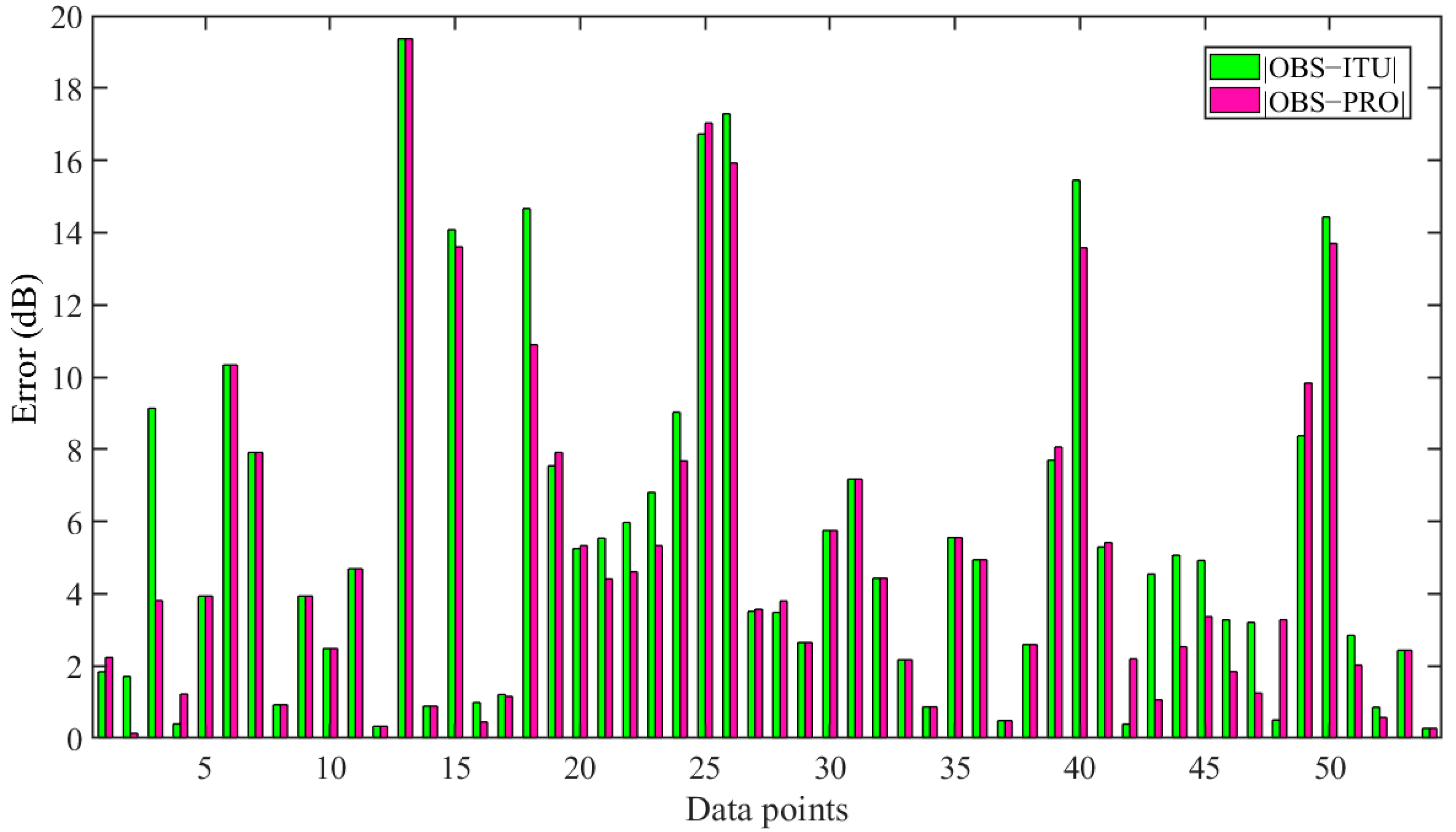
Figure 11 is a comparison of errors, where the column height is the magnitude of errors, and the horizontal axis is the corresponding receiving point (from near to far). It can be seen that the height of the column at medium and short distances is higher than that at long distances. According to statistics, 45 receiving points have an error difference of less than 1 dB, with 21 receiving points having the same error before and after improvement, particularly at night. The error of the 13th receiving point (about 700 km) is the largest, about 20 dB.
It is apparent that in the medium and short distance, where the receiving point is located, significant fluctuations and large errors are observed, possibly due to interference caused by the strong ground wave in this distance range. However, as the distance increases, the ground wave is significantly weakened, leading to a reduction in field strength fluctuations and smaller errors. Table 4 shows the RMSE between the measured field strength and the predicted field strength at near, medium, and far distances for the two methods. It can be seen that the error is larger at near and medium distances. However, at medium distances, the performance of the PRO method is significantly better than that of the ITU method. At far distances, the RMSE for both methods is greatly reduced and shows consistency, but the performance of the PRO method needs to be improved compared with the ITU method. Through the analysis, the accuracy of the PRO method is improved by about 3.69% compared to the ITU method.

3.5. Comprehensive Analysis

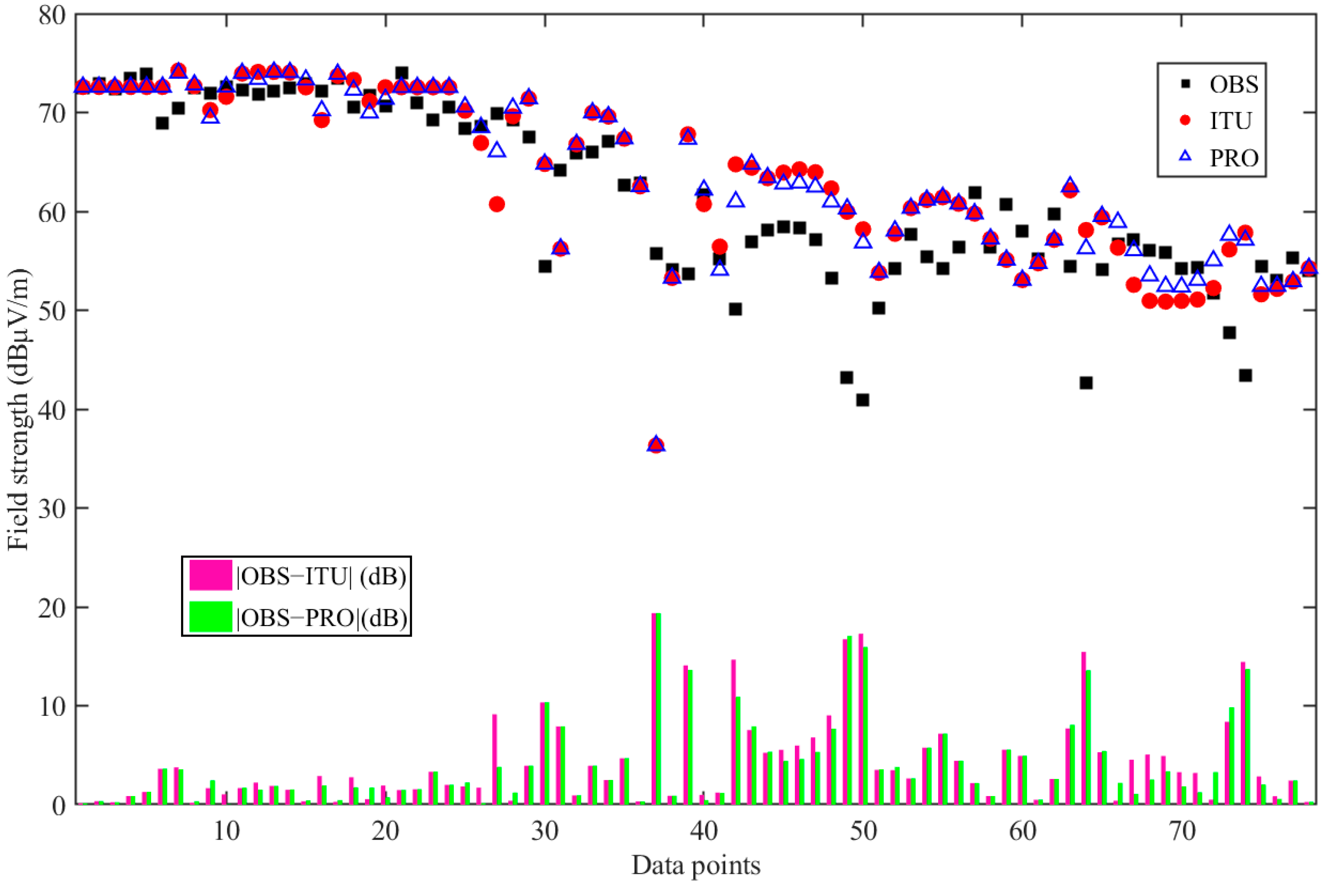
Figure 12 shows the overall comparison between the measured field strength and the predicted field strength based on the two methods and AEs between them. Through analysis, the RMSE between the predicted field strength based on the PRO method and the measured field strength of 78 improved point-to-point links is about 5.94 dB (where the RMSE between the two based on the ITU method is 6.17 dB), about 3.73% higher than that of the ITU method.
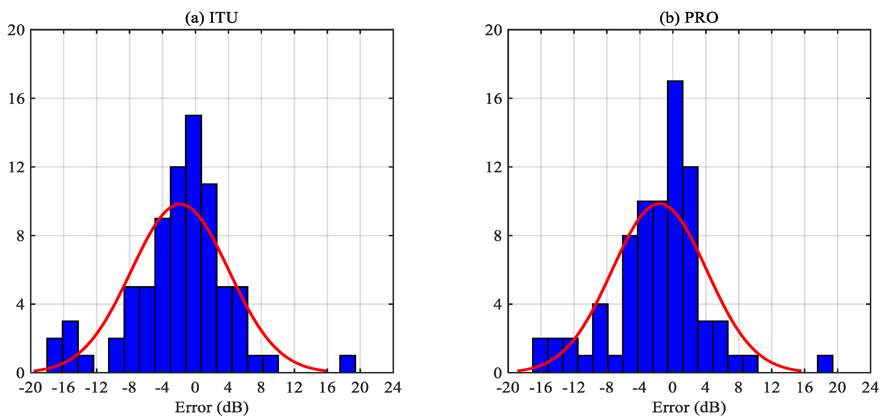
As shown in Figure 13, we conducted statistics on the overall error between the two methods (for ease of analysis, we removed the absolute value of AE, the measured value minus the predicted value). It can be seen that the error distribution roughly conforms to a normal distribution. Before the improvement, the measured field strength of 48 points is less than the predicted field strength, and the measured field strength of 30 points is greater than the predicted field strength. There are 19 points with an error ranging from −1 to 1 dB. After the improvement, the measured field strength of 46 points is less than the predicted field strength, and the measured field strength of 32 points is greater than the predicted field strength. There are also 19 points with an error of −1 to 1 dB, and 13 points with an error of 1 to 3 dB.
Section 3.2 illustrates that variation in ionospheric reflection height impact relevant parameters, ultimately influencing field strength. Considering the method outlined in Section 2, each parameter is interrelated, so improvements in one parameter alone cannot be isolated when assessing field strength changes. Notably, all parameters are directly or indirectly related to ψ, meaning even minor adjustments to ψ can cascade changes across parameters and subsequently impact field strength. Therefore, the alterations resulting from “Real-time reconstruction of ionospheric parameters” primarily stem from ψ. A statistical analysis reveals that the modification in ψ ultimately enhances field strength prediction accuracy by approximately 3.55% in this study.
By analyzing the time and spatial domain characteristics, Figure 14a,b compare the traditional and improved methods based on ITU. Using the transmitter as the center, we forecasted the field strength at JST = 12 in November 2013 over a range of 2000 km, including the Great Circle track. The change in the regional color from dark to light is the magnitude of field strength from low to high. It can be observed that the field strength fluctuation roughly follows the distribution form of concentric rings. When the propagation distance is relatively short, the regional color changes frequently, and the field strength fluctuates significantly. With the increase in distance, the regional color changes less, and the field strength fluctuates less, aligning with the spatial domain characteristics. Upon comparison, as opposed to the traditional method, the predicted field strength obtained with the PRO method exhibits more fluctuations when the propagation distance is relatively short, and the changes induced by the PRO method gradually decrease with the distance increase. Figure 14c shows the AE between (a) and (b). It can be seen that when closer to the transmitter, there are noticeable differences in field strength. However, as the distance from the transmitter increases, the changes in field strength become less significant.

4. Discussion

In this section, we will follow the method and process outlined, replacing the Kriging method with two other commonly used interpolation methods (Nearest and Linear) to seek model optimization. Table 5 and Table 6 show the improvement effects of these three interpolation methods compared to the ITU method in the time domain, spatial domain, and overall.
While the Nearest interpolation method has shown remarkable improvement in the time domain, it has hardly shown any enhancement in the spatial domain; instead, it has increased computational complexity. Linear interpolation, although exhibiting some improvement in the time domain, performs even worse in the spatial domain compared to the ITU method, and it also increases computational complexity. In contrast, the Kriging method utilized in this paper integrates improvements in both time and spatial domains, meeting the requirements of engineering applications and achieving multidimensional enhancement in LF propagation prediction. In conclusion, the Kriging method chosen in this paper demonstrates significant advantages.
However, the PRO method still has several limitations: (1) As mentioned earlier, fOE is difficult to observe at night. Even during the daytime, the observation equipment may be susceptible to various factors such as anthropogenic interference, leading to some reading errors. Therefore, data missingness and misalignment can greatly impact predictions based on the measured data. (2) The effectiveness of the Kriging method is easily influenced by the distances between ionospheric observation stations and between these stations and the target location.

5. Conclusions

Based on the wave-hop theory as outlined in the ITU method, this study incorporated real-time ionospheric forecast data in place of the long-term predictions typically used by the ionospheric model. Additionally, a detailed land–sea surface electrical characteristics map was utilized instead of a simple land–sea differentiation. These refinements improved the channel parameters, leading to greater accuracy in predicting LF skywave propagation field strength. By comparing and analyzing measurement data from 55 stations within 2000 km, we established a reasonable skywave propagation pattern and achieved accuracy improvements of 6.81% in the time domain and 3.69% in the spatial domain. Overall, the method showed an approximate improvement of 3.73% based on comprehensive analysis. Combined with Section 4, although the PRO method still has certain limitations, it achieves multi-dimensional accuracy improvements while maintaining computational efficiency, making it highly significant for engineering applications. Future research endeavors may focus on further optimizing prediction results by selecting more suitable observation stations, increasing their number, and refining ground electrical characteristics. Moreover, deeper exploration and analysis of long-distance multi-hop skywave propagation can be pursued by expanding the sample size.

Author Contributions

Conceptualization, J.W. and C.Y.; methodology, J.W., C.D. and Y.C.; software, J.W., C.D. and C.Y.; validation, C.D., Y.C., Y.S. and C.Y.; formal analysis, J.W., C.D. and Y.C.; investigation, J.W. and C.D.; resources, J.W., C.D. and Y.C.; data curation, J.W., C.D. and Y.C.; writing—original draft preparation, J.W. and C.D.; writing—review and editing, J.W., C.D., Y.C., Y.S. and C.Y.; visualization, J.W. and C.D.; supervision, J.W. and C.D.; project administration, J.W. and Y.C.; funding acquisition, J.W. and Y.C. All authors have read and agreed to the published version of the manuscript.

Funding

This research was funded by the National Natural Science Foundation of China (No. 62031008, U2341201).

Data Availability Statement

The raw data supporting the conclusions of this article will be made available by the authors on request.

Conflicts of Interest

Author Yu Chen was employed by Wuhan Marine Communication Research Institute, China State Shipbuilding Corporation Limited. The remaining authors declare that the research was conducted in the absence of any commercial or financial relation-ships that could be construed as a potential conflict of interest.

References

  1. International Telecommunication Union. ITU-R V.431, Nomenclature of the Frequency and Wavelength Bands Used in Telecommunications; International Telecommunication Union: Geneva, Switzerland, 2015. [Google Scholar]
  2. Appleton, E.V. The Propagation of Radio Waves over the Earth. Nature 1925, 115, 382. [Google Scholar] [CrossRef]
  3. Booker, H.G. Propagation of Wave-Packets Incident Obliquely upon a Stratified Doubly Refracting Ionosphere. Phil. Trans. R Soc. Lond. A 1938, 237, 411–451. [Google Scholar]
  4. Bracewell, R.; Budden, K.G.; Ratcliffe, J.; Straker, T.; Weekes, K. The ionospheric propagation of low- and very-low-frequency radio waves over distances less than 1000 km. J. Inst. Electr. Eng. 1951, 98, 221–236. [Google Scholar]
  5. Budden, K.G.; Chang, H. Radio Waves in the Ionosphere; Cambridge University Press: Cambridge, UK, 1962. [Google Scholar]
  6. Wang, J.C.H. An objective evaluation of available LF/MF sky-wave propagation models. Radio Sci. 1999, 34, 703–713. [Google Scholar] [CrossRef]
  7. Warrington, E.M.; Jones, T.B. Propagation of low-frequency radio waves. IET Microw. Antennas Propag. 2000, 147, 35–42. [Google Scholar] [CrossRef]
  8. Liu, J.; Wu, G.; Liang, Z. The effect of atmospheric refraction on the calculation of skywave propagation geometry parameters. J. Xidian Univ. 2002, 29, 47–51. [Google Scholar]
  9. Wakai, N.; Kurihara, N.; Otsuka, A. Numerical Method for Calculating LF Sky-Wave, Ground-Wave and Their Resultant Wave Field Strengths. Electron. Lett. 2004, 40, 288. [Google Scholar] [CrossRef]
  10. Wakai, N.; Kurihara, N.; Otsuka, A.; Imamura, K.; Takahashi, Y. Wintertime Survey of LF Field Strengths in Japan. Radio Sci. 2006, 41, 2005RS003344. [Google Scholar] [CrossRef]
  11. Wang, J.C.H. Seasonal Variation of LF/MF Sky-Wave Field Strengths. IEEE Trans. Broadcast 2008, 54, 437–440. [Google Scholar] [CrossRef]
  12. Shigeru, T.; Kuniyasu, I.; Hiroyuki, I.; Hideo, M.; Minoru, K.; Kenro, N. 2-9 Prediction method and proof measurement of LF standard frequency waves. J. Natl. Inst. Inf. Commun. Technol. 2010, 57, 103–116. [Google Scholar]
  13. Feng, B.; Lv, Y. Approximate solution for vertically polarized VLF/LF waves in lower ionosphere. In Proceedings of the ISAPE2012, Xi’an, China, 22–26 October 2012. [Google Scholar]
  14. Pal, S.; Hobara, Y.; Chakrabarti, S.K.; Schnoor, P.W. Effects of the major sudden stratospheric warming event of 2009 on the subionospheric very low frequency/low frequency radio signals. J. Geophys. Res. Space Phys. 2017, 122, 7555–7566. [Google Scholar] [CrossRef]
  15. Zhou, L.; Wang, D.; Mu, Z.; Xi, X.; He, L. LF Radio Wave Prediction at Short Ranges with High Propagation Angles Over Irregular Terrain. IEEE Antennas Wirel. Propag. Lett. 2017, 16, 732–735. [Google Scholar] [CrossRef]
  16. Melchinov, V.; Pavlov, A.; Soloviev, B.; Bashkuev, Y.; Dembelov, M. The Seasonal Variations of LF-MF Electromagnetic Waves on Permafrost Radio Paths. In Proceedings of the 2019RWP, Kazan, Russia, 23–24 August 2019. [Google Scholar]
  17. Zhou, L.; Yan, J.; Mu, Z.; Wang, Q.; Liu, C.; He, L. Study on Time Delay Characteristics of Low Frequency One-hop Sky Waves in the Isotropic Ionosphere. J. Electron. Inf. Technol. 2020, 42, 1606–1610. [Google Scholar]
  18. Gasdia, F.; Marshall, R.A. A New Longwave Mode Propagator for the Earth–Ionosphere Waveguide. IEEE Trans. Antennas Propag. 2021, 69, 8675–8688. [Google Scholar] [CrossRef]
  19. Mu, Z.; Wang, Q.; Zhou, L.; Hu, X.; He, L. Comparison of low frequency multi-hop sky wave delay estimation algorithms. Chin. J. Radio Sci. 2022, 37, 244–250. [Google Scholar]
  20. Zhao, Z.; Liu, J.; Pu, Y.; Zhang, J.; Xi, X. Analysis of low-frequency sky wave signal characteristics based on IRI ionospheric model. Chin. J. Radio Sci. 2022, 37, 898–904. [Google Scholar]
  21. Gao, J.; Pu, Y.; Zhao, Z.; Zhao, Z.; Xi, X. An Improved Model for Loran-C One-Hop Sky Waves Propagation at Short-Range. IEEE Antennas Wirel. Propag. Lett. 2023, 22, 1–5. [Google Scholar] [CrossRef]
  22. International Telecommunication Union. ITU-R P.368-10: Ground-Wave Propagation Prediction Method for Frequencies between 10 kHz and 30 MHz; International Telecommunication Union: Geneva, Switzerland, 2022. [Google Scholar]
  23. International Telecommunication Union. ITU-R P.1239-3: ITU-R Reference Ionospheric Characteristics; International Telecommunication Union: Geneva, Switzerland, 2012. [Google Scholar]
  24. Pan, W. Long wave sky wave propagation. In LF VLF ELF Wave Propagation; UESTC Press: Chengdu, China, 2004. [Google Scholar]
  25. Recommendation ITU-R P. 684-6: Prediction of Field Strength at Frequencies below about 150 kHz; International Telecommunication Union: Geneva, Switzerland, 2012.
  26. Stanisκawska, I.; Juchnikowski, G.; Cander, L. Kriging method for instantaneous mapping at low and equatorial latitudes. Adv. Space Res. 1996, 18, 217–220. [Google Scholar] [CrossRef]
  27. Mukesh, R.; Soma, P.; Karthikeyan, V.; Sindhu, P. Prediction of ionospheric vertical total electron content from GPS data using ordinary kriging-based surrogate model. Astrophys. Space Sci. 2019, 364, 1–12. [Google Scholar] [CrossRef]
  28. Wang, J.; Bai, H.; Huang, X.; Cao, Y.; Chen, Q.; Ma, J. Simplified Regional Prediction Model of Long-Term Trend for Critical Frequency of Ionospheric F2 Region over East Asia. Appl. Sci. 2019, 9, 3219. [Google Scholar] [CrossRef]
  29. Rhoads, F.J.; Garner, W.E. An Investigation of the Modal Interference of VLF Radio Waves. Radio Sci. 1967, 2, 539–546. [Google Scholar] [CrossRef]
Figure 1. Geometric diagram of skywave propagation path within 2000 km. (a) One-hop propagation (without diffraction). (b) One-hop propagation (including diffraction). (c) Two-hop propagation (without diffraction). (d) Two-hop propagation (including diffraction).
Remotesensing 16 02241 g001
Figure 2. Observation stations selected for reconstruction.
Remotesensing 16 02241 g002
Figure 3. Comparison of variation pattern of ionospheric reflection height hr and fOE when JST = 12 in East Asia. (a) fOE of the ITU method. (b) fOE of the improved method. (c) The difference in fOE between the ITU method and the improved method. (d) hr of the ITU method. (e) hr of the improved method. (f) The difference in hr between the ITU method and the improved method.
Remotesensing 16 02241 g003
Figure 4. Changes in land–sea surface electrical characteristics in East Asia. (a) The land–sea distinction in the ITU method. (b) Refined land electrical characteristics.
Remotesensing 16 02241 g004
Figure 5. Comparison of the variation in relevant parameters in East Asia. (a) ψ of the ITU method. (b) ψ of the PRO method. (c) The difference in ψ between the ITU method and the PRO method. (d) i of the ITU method. (e) i of the PRO method. (f) The difference in i between the ITU method and the PRO method. (g) D of the ITU method. (h) D of the PRO method. (i) The difference in D between the ITU method and the PRO method. (j) Fr of the ITU method. (k) Fr of the PRO method. (l) The difference in Fr between the ITU method and the PRO method. (m) R of the ITU method. (n) R of the PRO method. (o) The difference in R between the ITU method and the PRO method.
Remotesensing 16 02241 g005
Figure 6. Location of the transmitter and fixed receiver. Green ●: transmitter location. Blue ▼: fixed receiver location.
Remotesensing 16 02241 g006
Figure 7. The variation pattern of field strength with time. Blue ●: measured field strength at the corresponding moment. Red square line: predicted field strength of the ITU method. Green triangle line: predicted field strength of the PRO method.
Remotesensing 16 02241 g007
Figure 8. Variation of errors over time. (a) Error: |OBS − ITU|. (b) Error: |OBS − PRO|. Gray double-dash line arc: contour of error (1 dB difference per circle).
Remotesensing 16 02241 g008
Figure 9. Location of the transmitter and mobile receivers. Green ●: transmitter location. Blue ▼: mobile receiver locations.
Remotesensing 16 02241 g009
Figure 10. The variation pattern of field strength with distance at different hours. Blue ●: measured field strength at the corresponding distance. Blue double-dash line: predicted field strength of the ITU method. Red solid line: predicted field strength of the PRO method. Horizontal axis: distance (km). Vertical axis: field strength (dB (μV/m)).
Remotesensing 16 02241 g010
Figure 11. Variation of errors over distance. Green column: error (|OBS − ITU|). Pink column: error (|OBS − PRO|). Horizontal axis: corresponding receiving point.
Remotesensing 16 02241 g011
Figure 12. Comparison of the overall field strength. Black ■: measured field strength. Red ●: predicted field strength of the ITU method. Blue △: predicted field strength of the PRO method. Pink column: error (|OBS − ITU|). Green column: error (|OBS − PRO|).
Remotesensing 16 02241 g012
Figure 13. Overall error statistics of the two methods. (a) ITU method. (b) PRO method. Blue column: histogram of frequency distribution. Red solid line: normal distribution curve.
Remotesensing 16 02241 g013
Figure 14. Method comparison. (a) ITU method. (b) PRO method. (c) |ITU−PRO|.
Remotesensing 16 02241 g014
Table 1. The electric characteristic parameters of the land–sea surface correspond to different color squares.
MethodBefore Refinement—(a)After Refinement—(b)
ColorBlueDark GreenLight BlueGreenGreyPurple
Permittivity, ε (F/m)80157030153
Conductivity, σ (S/m)50.00250.010.0010.0001
Table 2. Specifications for 40 kHz radio wave transmitters.
Specific Information
Transmitting StationJJY
PlaceFukushima, JPN
Longitude140.8°E
Latitude37.4°N
Antenna typeStayed monopole of umbrella type
Antenna height250 m
Transmitter power50 kW
Carrier frequency40 kHz
Radiation efficiency25%
Table 3. RMSE during day and night based on the two methods.
MethodsITUPRO
Day1.93 dB1.70 dB
Night1.88 dB
Table 4. RMSE at different propagation distance stages based on the two methods.
Distances200~800 km800~1400 km1400~2000 km
ITU7.48 dB9.57 dB5.85 dB
PRO7.42 dB7.65 dB5.99 dB
Table 5. Time improvement effects of three interpolation methods compared to the ITU method.
MethodsKrigingNearestLinear
Improvement6.81%9.95%6.28%
Table 6. Spatial improvement effects of three interpolation methods compared to the ITU method.
MethodsKrigingNearestLinear
Improvement3.69%0.20%−0.82%
Disclaimer/Publisher’s Note: The statements, opinions and data contained in all publications are solely those of the individual author(s) and contributor(s) and not of MDPI and/or the editor(s). MDPI and/or the editor(s) disclaim responsibility for any injury to people or property resulting from any ideas, methods, instructions or products referred to in the content.