Abstract
The precise identification of railway subgrade defects remains a significant challenge for the railway industry globally. Due to the limitations of individual monitoring techniques, comprehensive information on subgrade defects cannot be obtained. In fact, the presence of subgrade defects can significantly increase the risk of traffic accidents during high-speed train operations, which may affect the safety of train operations and economic development. The monitoring of subgrade health status is used as a pre-disaster planning method that is urgently required to avoid accidents and guide the maintenance strategy. Therefore, a novel “integrated” holistic monitoring approach for subgrade structures is presented based on satellite remote sensing, a comprehensive inspection vehicle, and a ground-based testing technique. Additionally, the monitoring content is more clearly defined during the service life of the subgrade. The method is used to investigate the location, development trend, and the cause of subgrade defects on the Shanghai–Nanjing high-speed railway. Some new viewpoints are put forward: First, the monitoring content for assessing the health status of the subgrade should encompass the foundation settlement, the track geometry status, and the monitoring of deformation and defects within the subgrade. Second, the mileage points K235 and K299 of the subgrade, as well as K236 and K237 of the bridge–subgrade transition sections, are estimated to be locations with potential defects based on the differential InSAR and track quality index. Third, the result of settlement monitoring and ground-penetrating radar analysis illustrates that sections K235 +540 to +680 and K299 +680 to +750 are diagnosed as defect positions triggered by the rapid drop of water level and engineering activity, respectively. Fourth, the “integrated” holistic monitoring technique for subgrade service status might be expected to be a promising method that can be useful in developing maintenance plans and implementing fault recovery for railway infrastructure.
1. Introduction
By the end of 2022, the length of the operating railways in China had increased to a total of 155,000 km (including over 42,000 km of high-speed railways), and China had become the country with the largest operating mileage in the world [1]. The over-increased embankment and railway-cutting slope have led to the destruction of the original geological balance; thus, the railway is susceptible to disasters during operation in extreme climates. For example, in 2020, a train derailed at position K302 +500 of the Litang–Zhanjiang railway, caused by a subgrade collapse, which resulted in railway disruption of up to 41 h and a cost of CNY 14.46 million [2]. In 2020, the railway derailment accident of the Beijing–Guangzhou railway was also triggered by a subgrade collapse, resulting in 122 people injured and a loss of CNY 22.35 million [2]. As a result, the frequent accidents caused by subgrade defects are major impediments to the development of transportation and the economic efficiency of railways.
The Shanghai–Nanjing High-Speed Railway (SNHR) is mainly located in a typical coastal soft soil area that is often affected by typhoons and rainstorms after the “El Nino” event. In addition, the subgrade stability is also affected by soil foundation deformation, construction activities, and train load. Therefore, the number of subgrade defects is continuously increasing due to several factors, making the investigation of subgrade health status much more difficult. Detection or monitoring of subgrade service status is always regarded as a pre-disaster planning measure. Early warning and prevention activities are conducted to minimize the damage caused by subgrade defects. Therefore, accurate recognition of defects and railway health monitoring is crucial for the safe operation and disaster prevention of railways. Recently, the method of detection or monitoring of infrastructure status on railways has mainly contained four aspects according to technical type.
First, the evaluation of track irregularity mainly relies on the power spectral density based on amplitude and wavelength [3,4] and the evaluation method of track quality. In addition, the evaluation method of track quality is always represented by the standard deviation or maximum value of irregularity amplitude with specific track parameters, which is often used to guide the temporary repair and the management of speed limitations. The track quality index is typically determined by calculating the standard deviation of track parameters within a specific section. The Q-index takes into account the ratio of average standard deviations of level and alignment corresponding to threshold limits in the Swedish National Railway [5]. The W5 track defectiveness index was proposed by the Australian Rail Track Corporation and is based on five parameters of track defectiveness (profile, alignment, gauge, cant, and twist) [6]. The TGI index of the Indian Railway focused on the weighted average of surface, twist, gauge, and alignment [7]. The J index in Poland was a weighted average of surface, alignment, warp, and gauge [8]. The P index adopted by the Japanese Railway was the percentage of mileage with track deviation exceeding 3 mm to the 100 m or 500 m lengths of track segments [9]. Every country chooses an appropriate track condition index to reflect the real state of the track based on its own experience of track maintenance. However, the Chinese Track Quality Index (TQI) was proposed by accumulating the standard deviation of seven geometric deviations in a 200 m railway unit, and its management standards of track irregularity for 250–350 km/h high-speed railways are used to maintain the railway structure, which is more stringent than the European norm [10]. The comprehensive inspection train of each country can obtain the track quality index at the same speed as a high-speed train and can consider the wheel–rail interaction effect in the real state. But, subgrade defects are only one of the factors that cause track geometric irregularities [11]. Thus, the track deviation cannot directly reflect the deterioration of the railway subgrade [5] and is also subjected to the impact of certain environmental factors [12].
Second, there is a ground-based monitoring technique. Precision leveling and total stations are often adopted to collect the elevations of the track vertical control network (CPIII), which are widely used in railway management departments in various countries [13]. The subgrade settlement with millimeter magnitudes is obtained at different periods by these methods. In addition, the sedimentation plate method, single-point settlement, and the magnetic ring-layered sedimentation method are also used to gain high-accuracy deformation information for subgrades. However, manual measuring techniques require a lot of time and labor costs. Fiber Bragg grating and GPS (Global Positioning System) have been utilized to automatically monitor the collapse and long-term deformation of the subgrade in recent years [14]. But, real-time monitoring techniques require many devices/sensors, which is impractical for covering the whole subgrade.
Third, InSAR (interferometric synthetic aperture radar) interferometry technology has the advantages of wide coverage, non-intrusive surveying, and remote monitoring [15], which is often used to monitor surface subsidence that is caused by external environmental factors and human engineering activities during the long-term service of the railway. Various studies have highlighted that the deformation of railway infrastructure can be indirectly reflected by analyzing the influence of ground settlement around the railway on the subgrade, e.g., differential subsidence caused by the overexploitation of groundwater [16], karst collapse [17], mining [18], and engineering construction activities [19]. Even though displacements measured by differential interferometric InSAR are evaluated with millimeter-level precision, the positioning precision of scatterers is relatively low [20]. Moreover, the interferometric coherence of InSAR will be affected in areas with vegetation or complicated terrain topography [21,22].
Fourth, traditional manual patrols are still widely conducted in routine detection. However, if subgrade defects like cracking, large settlement, and mud pumping can be detected by visual inspections, then the degree of subgrade deterioration is very serious. In other words, the subgrade undergoing creep or internal failures is undetectable by surface visual inspection alone. But, the result of visual inspection is mainly dependent on the specialized knowledge of technicians. Non-destructive testing methods such as ground-penetrating radar (GPR) can detect information on the loose area, holes, water accumulation, and local distortion inside the subgrade [23]. Additionally, the development trend of subgrade deterioration can also be carried out by qualitative predictions. However, the methods of GPR image interpretation are considered to be time-consuming and require significant experience [24].
Great progress has been made in current studies, and the monitoring methods are constantly innovating and have multiplied with the development of science and technology. However, there are still three limitations that need to be further studied: First, the monitoring subjects are not comprehensive enough, and the technology system is not yet perfected in current practical applications of subgrade state monitoring. If infrastructure degradation or a worsening environment cannot be detected in a timely manner, it may threaten the safe operation of trains and cause traffic accidents. Second, the service status of the subgrade is almost imperceptible due to it being covered by an enclosed waterproof sealing structure. The standalone use of comprehensive inspection vehicles, leveling, and InSAR cannot be considered to be an impeccable solution for detecting subgrade defects on the whole railway line. Third, it is difficult to estimate subgrade defects accurately during railway operations due to the lack of comprehensive analysis ability for multisource data and the capabilities to retrieve key information from massive data.
The integrated monitoring approach has been implemented in many research fields like volcano [25,26], forest fire [27,28], and hazard monitoring [29,30]. However, the implementation of various monitoring technologies for the detection of subgrade defects is still at the exploratory stage. Therefore, this work aims to integrate multisource and multiscale monitoring technologies, leveraging the unique advantages of InSAR, comprehensive vehicle inspection, leveling, and GPR to monitor the health status of subgrades and investigate defects. In this work, the external hazards threatening the stability of the subgrade and monitoring the content of the subgrade structure are more clearly defined during the subgrade service process. An integrated technique of multimeasures is proposed to identify the potential defect locations, monitor the critical deformation areas, and investigate the cause of subgrade defects in detail. The method is applied in SNHR. The detailed procedure and the shortcomings of this integrated method are also described and discussed, respectively. It should be noted that this “integrated” holistic monitoring technique for subgrade service status may be expected to be a promising method that can provide valuable insights for the safe operation and disaster prevention of railways.
2. Study Area
The SNHR is in Shanghai and Jiangsu Province, with a total mileage of 300 km and a design speed of 350 km/h. About 33.6% of the railway structure consists of subgrade throughout the entire mileage. SNHR is one of the railways with the highest proportion of subgrade in China. The K228~K299 section of SNHR is selected as the study region in Nanjing City, Jiangsu Province (Figure 1). This study area has a humid subtropical climate with 1090 mm average annual rainfall [31] and has often suffered from typhoons and rainstorms. The study area focuses on the Yangtze River coast, which has a well-developed water network that has led to the widely distributed alluvial deposits of soft soil. Soft soil is characterized by high water content, low strength, and high compressibility [32]. As shown in Figure 1c, the region is extensively covered by Quaternary strata, which are primarily composed of sedimentary soils, including soft soil, silt, and clay formed by fluvial and alluvial deposition in river floodplains [33]. The pile–raft, and pile–net composite foundations were mainly used in the foundation treatment of SNHR. In addition, intensive human engineering activity has become a critical factor that causes ground subsidence during the period of urbanization in this study area, such as groundwater extraction, deep foundation pit engineering, and metro construction [34].
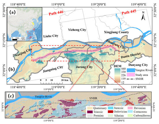
Figure 1.
Location map of Shanghai–Nanjing High-Speed Railway (SNHR) in Jiangsu Province. (a) Map of China’s administrative boundaries, and the yellow area is the location of Jiangsu province. (b) Map of digital elevation model (DEM) in this study area. (c) Lithology map in red dashed line.
3. Data
This study utilized five types of multisource and multiscale-monitoring data techniques. (1) ALOS PALSA operated in a radar carrier frequency of 1270 MHz (L band) with an incidence angle range of 8~46 degrees in dual polarization mode, which can penetrate the vegetation and reach the ground. Two ALOS PALSA data sets were prepared to obtain the deformation (Figure 1 and Table 1). The level 1.5 georeferenced amplitude image with 15 m spatial resolution was Single Look Complex (SLC) data in vertical transmit and vertical receive (VV) mode. The data were derived from the ASF (Alaska Satellite Facility) website. (2) Digital elevation model (DEM) (12.5 m × 12.5 m) data generated on 3 May 2008 was also obtained from the sensor of ALOS PALSAR. (3) Track Quality Index (TQI) indicated the track irregularity which was recorded by the comprehensive track inspection train of Shanghai Railway Bureau. It realistically represents the quality state within the 200 m track section. (4) A precise leveling method was used to measure the vertical settlement of the CPIII control network of subgrades in key railway sections. (5) Ground-penetrating radar was used to investigate subgrade internal structure information, detect structural cavities and hydraulic channels, and collect other subgrade defect information.

Table 1.
Parameters of ALOS PALSA SAR data over the study area.
4. Methods
4.1. Differential Radar Interferometry (D–InSAR)
D–InSAR technique can detect minor surface deformation by differential interference of two SAR images obtained from two different positions and visit times. Two SAR images are coregistered by offset estimation of image matching. The initial interference phase can be acquired by pixels of the master image multiplied by the complex conjugate of the corresponding pixel of the slave image. The interferometric phase can be expressed as follows:
where indicates the initial interference phase. expresses the flat earth phase. is the topographic phase. donates the atmospheric delay phase. is the deformation phase. is the residual noise phase. The SAR images are processed with the assumption of a flat earth. Hence, the phase difference between the flat and actual earth should be considered, which can be expressed as follows:
where the is the parallel baseline for each pixel. The topographic phase is the phase component of the terrain caused by the terrain fluctuation, which is proportional to the vertical baseline. As shown in Equation (3):
where the indicates the parallel baseline for each pixel. R is the distance between the target and the satellite. is the antenna look angle, and is the topography above the reference ellipsoid (Figure 2). The topographic phase can be removed using the external DEM data. is the atmospheric delay phase, which is estimated by external measurements or atmospheric models [35]. indicates the interferometric phase noise, it is removed by filtering via the SAR imaging software of ENVI 5.3. The deformation interferometric phase is caused by the deformation of the target object as shown as follows:
where is the radar wavelength, is the deformation value.
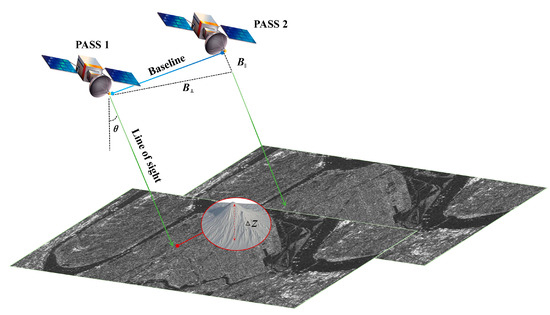
Figure 2.
Repeat pass interferometry and geometric relationship of LOS (Line of sight) and radar slant plane.
To obtain the surface deformation, the interferogram results after filtering should be unwrapped first because it is wrapped around modulus 2π with amplitude images as background. The coherence value of each pixel is calculated at the same time. In this work, the minimum cost flow (MCF) is used to unwrap the phase by network planning, and the pixels whose coherence is lower than predefined are masked [36]. In addition, orbit refinement and reflattening are needed to correct satellite orbit and phase offset before generating the deformation map, which makes its spatial coordinate information more accurate. Finally, the phase is converted into the deformation value. However, the map is in the SAR image coordinate system, which should be converted to the geographic coordinate system using the geocoding method.
4.2. Settlement Monitoring and Track Quality Index (TQI)
Subgrade settlement is measured by precision leveling based on the difference of elevation control points of CPIII at different times. The round-trip mapping method is adopted to measure the subgrade settlement of SNHR. The measurement error of precision level is limited to ±0.3 mm. The monitoring frequency of key railway sections depends on the degree of deterioration of the railway structure.
TQI is a management method of average value, which reflects the fluctuation of track geometric irregularity in a 200 m railway unit. It is also an accumulative value of the standard deviation of seven geometric deviations (longitudinal level of left and right, left and right alignment, cross-level, gauge, and track twist). The comprehensive inspection train was used to obtain the TQI data of SNHR every 30–60 days. TQI management threshold is 5 mm for high-speed railways with a maximum allowable speed of 250–350 km/h, and the TQI is given as follows:
where δi is the deviation of a single index, including the left and right longitudinal level, left and right alignment, cross-level, gauge, and track twist.
where N indicates the sampling number in the 200 m railway unit, is the average value of the peak of single sampling Xij (j = 1,2,3, ..., N) in each geometric parameter (i = 1, 2, ...,7).
4.3. Exploration Using Ground-Penetrating Radar (GPR)
GPR can survey the locations and sizes of different electrical layers and objects within materials. Various soil layers have different electrical properties, and the incident wave generates different reflected signals when it pulses into unique media, while the rest of the wave will continue to propagate. The antenna of the device receives reflected signals, and the reflected energy is displayed as a waveform, which shows amplitudes and time elapses between wave transmission and reflection. Hence, defect signal features inside the subgrade can be detected after data preprocessing like enhanced signal-to-noise ratio. The characteristics of railway subgrade defects in GPR images can be identified by visual interpretation. For example, the image of water accumulation typically exhibits large amplitude, reverse phase, and multiple reflections at the interface. Because the amplitude reflection of the water accumulation layer is strong, it filters the high-frequency electromagnetic waves and leaves low-frequency waves. The image characteristic of subsidence shows that the reflected signals of the interface between the surface and the bottom layer of the subgrade exhibit significant bending, discontinuity, and offset of the depth downwards [37]. Reflected signals of different intensities are represented by hexadecimal colors based on GPR analysis software. As shown in Figure 3, the waveforms of electromagnetic signals are transformed into reflection signals. The reflection intensities of the khaki color in the middle are relatively weak.
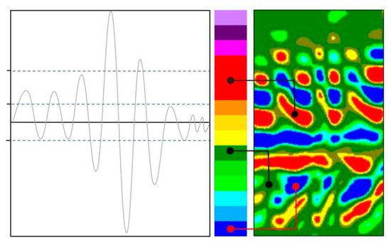
Figure 3.
Waveform of electromagnetic signals and reflection signals.
5. Results
5.1. Land Subsidence along the Shanghai–Nanjing Railway
Due to the impact of overexploitation of groundwater, subway construction, and heavy loading of high-rise buildings, the problem of land subsidence occurs frequently in soft soil areas [38]. The land subsidence will harm the railway subgrade and affect the function of urban infrastructure and railway tracks. Therefore, the D–InSAR technique was adopted to obtain the land subsidence in the range of 1 km covering the region along SNHR after the railway operation (1 July 2010). Subsequently, the geological environment of the railway was monitored, and the areas of land settlement that may affect the smoothness of the subgrade were delineated. The value of ground displacement in the radar line-of-sight (LOS) direction was measured (Figure 4). Positive LOS deformation (blue colors) indicates movement towards the satellite. Conversely, the red color area (negative LOS deformation) represents the movement away from the satellite (like land subsidence).
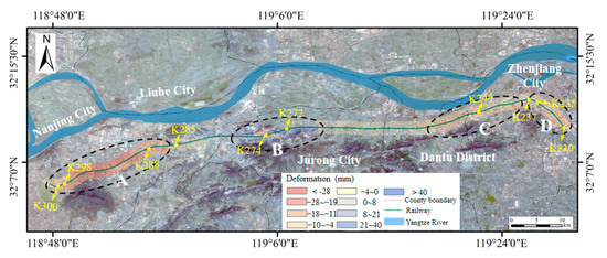
Figure 4.
The deformation map along the K230 to K300 of the high-speed railway from radar line-of-sight (LOS) direction.
The differential interference result shows that the significant subsidence is mainly located in area A (black oval dotted line A in Figure 4) in the K288~K300 railway section. The maximum value of subsidence is over −28 mm near the railway in Nanjing City. The deformation in subgrade section K298~K300 is about −10~−15 mm. Moreover, the deformation in the range of −28~−10 mm is mostly located in section K288~K298 (10 km length), and the railway line in this section was mainly composed of bridges with 24~32 m prestressed concrete box beams. Although the surface settlement is relatively large, it has little impact on the bridge foundation structure. Meanwhile, the uplifted region is mainly distributed in the B section, located at the border area of Jurong City, where the landform is mainly characterized by hilly and mountainous terrain with an altitude of 300 m. There is a railway tunnel of about 2000 m, and the land uplift value is about 40~60 mm. The subsidence is comparatively low in the plain area of section C (Figure 4). The surface subsidence of the K237~K244 section is within ±4 mm in most areas, and the structure of the railway is constructed as a low embankment in this region. Conversely, another region of section C is characterized by depression with relatively low terrain. Therefore, bridges and high embankments are built to maintain the slope of the railway and meet the requirements of smoothness in this area. Furthermore, the surface subsidence is about −8~−6 mm at the K235 mileage point. The groundwater level of the subgrade may be vulnerable to the fluctuation of the river, as this area is close to the river (less than 100 m). This area should be monitored by the railway bureau in the dry season.
Above all, the significantly large land subsidence is evident at mileage point K235, and the K298~K300 section (2 km in total) is very likely to damage the subgrade sections. The deformation of the foundation triggered by regional subsidence will directly damage the structure of the subgrade, resulting in subsidence and other defects. However, the subgrade defects are exacerbated under the cyclic load of trains, which will affect the strength and smoothness of the railway subgrade, potentially leading to disruptions in rail traffic and operational accidents. Hence, the question of whether the subgrade has deteriorated due to environmental factors should be considered by combining the TQI data for further study. If irregularities arise in these areas of the railway line, indicating the deteriorating state or defect in these positions.
5.2. Track Irregularity Detection by Track Quality Index (TQI)
The critical factors affecting track smoothness are the abrasion of track components and the loosening of rail fastenings. Furthermore, the corrosion of rail and fasteners and cracks in sleepers will cause changes in track geometry, which are often aggravated by the dynamic load of the train. But, the irregular state of the railway will be improved by railway conservation using vibration machines, and there are not only monthly minor repairs, but there are also major repairs once every 6~12 months. Another reason for geometric irregularity is the uneven settlement of the subgrade. Hence, the TQI consistently exceeded the threshold management threshold (TQI ≥ 5) after tamping by the device, which may be caused by subgrade deterioration.
Five TQI data points are recorded for each kilometer mileage, with each data point representing 200 m of the unit segment. For example, the TQI data of the K235 mileage point contains units of K235 +200, +400, +600, +800 and K236 +000. Hence, the data from a total of 20 periods were used to analyze the geometric smoothness state along the K230 to K300 sections of the high-speed railway from 16 August 2010 to 20 February 2014 in this work. It is demonstrated that the TQI value of sections was relatively high from 2010 to 2014 in sections such as K235, K236, K237, K239, K299, and so on (Figure 5a,b). The highest value of TQI was 13.3 mm on 15 February 2011. The TQI value is about 5.16~7.7 mm from section K235 +200 to K236 +800 and about 5.08~10.3 mm in section K298 +800~K300. Notably, the TQI value of all these sections has exceeded the management threshold (TQI ≥ 5 mm). The railway mileage, number of TQI threshold overruns, maximum TQI value, and track formation type were collected in Table 2. In this research, the notation “Kxyz” is used to represent the railway mileage along the SNHR, where “K” represents “kilometer” and “xyz” indicates the specific mileage point. It was indicated that exceeding threshold frequency was 58, 46, and 31 times in mileage points K235, K299, and K237, respectively. The structural type of K235 and K299 is subgrade. Furthermore, the bridge–subgrade transition in track geometric irregularity is also prominent in mileage points K236, K239, and K241 due to different settlements caused by differences in the rigidity of the soil subgrade and concrete bridge.
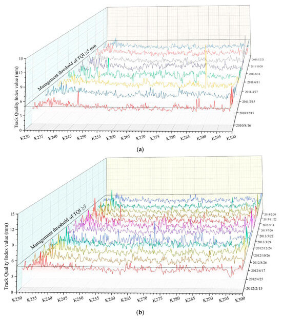
Figure 5.
Track quality index (TQI) reflecting geometric irregularities acquired from comprehensive inspection trains along the K230 to K300 sections of the high-speed railway. (a) TQI data from 2010 to 2011, (b) TQI data from 2012 to 2014.

Table 2.
Frequency of TQI above management threshold in various railway mileage points.
In some mileage points where the threshold is only exceeded a few times, it may be caused by an error in the measurement of deviation or other defects of rail. Nevertheless, it will be improved after track maintenance. For instance, track irregularity occurred three times in the subgrade mileage point K246 (appearing at K246 +400) on 15 February 2011 and 22 May 2013. However, no irregularities were observed in other inspections. The same phenomenon occurred in the bridge–subgrade transition of mileage point K232 (specifically in K232 +800 to K233 +000). The smooth state of the track was improved after repair. Consequently, mileage points K235, K236, K237, and K299 should be considered to be potential defective areas because the track irregularity was still detected in these subgrade mileage points even after being repaired by the tamping machine and restored by the workers.
5.3. Settlement Monitoring and Ground-Penetrating Radar Survey
Using InSAR, an area of land subsidence was observed at mileage points K235, K298, and K299, which may affect the subgrade. Additionally, the geometric smoothness of the track, as indicated by TQI (Track Quality Index) data, can assist in locating potential defects. Therefore, the four mileage points (K235, K236, K237, and K299) with the highest frequency of TQI exceeded the threshold and were selected as the key observation areas, while the K298 mileage point was excluded. The tracks on these four mileage points were continuously found to be uneven. Among them, two mileage points, i.e., K235 and K299, were severely affected by ground settlement. These four key locations, spanning a 70 km stretch of the railway (from K230 to K300) across four cities, significantly reduce the workload for a detailed field survey. Therefore, the settlement monitoring data are obtained by measuring the CPIII control network for the ballastless track of the high-speed railway using a precise leveling technique. It is crucial to emphasize that the post-construction settlement of the subgrade is usually strictly controlled, ensuring that the deformation does not exceed 15 mm.
The cumulative vertical settlement of the railway cross-section in sections K235 +390 to K236 +335 and K279 +368 to K279 +992 was displayed by field investigation, as shown in Figure 6. It is observed that the settlement at positions K235 +587, K236 +050, and K236 +095 exceed the standard value of deformation (15 mm). The position K235 +587 was the most severely deformed location (up to −46 mm), and the displacement at sections K236 +050 and K236 +095 was −17.7 and −16.8 mm, respectively. Figure 7 shows the relationship between cumulative settlement and time variation at the specific position, and the settlement was found to increase with time from 2012 to 2014. It could be suggested that the settlement of the subgrade is progressively deteriorating, and this status cannot be improved by routine maintenance. The excessive settlement observed at these three positions has persisted for over a year. Therefore, the subgrades K235 +587, K236 +050, and K236 +095 were identified as the defect positions. TQI value exceeded the management threshold (5 mm) over 31 times at the K237 mileage point, but the settlement never exceeded the settlement control standards (15 mm). Thus, this site was not observed as the defect location. The differential settlement was observed between the bridge and subgrade due to the differences in the rigidity of the soil subgrade and concrete bridge. Subsequently, the track irregularity state is detected in the subgrade side based on TQI when the train passes through here. However, this irregular state can be repaired by tamping devices or by enhancing the stiffness of the subgrade or slab using grouting technology. Figure 8 illustrates the subgrade deformation at K299 +235 to K299 +800 in 2014. The observed deformations were minor and did not exceed 5 mm. It is observed that the subgrade is still in good working condition in terms of settlement.

Figure 6.
Monitoring data of accumulated settlement at different locations.
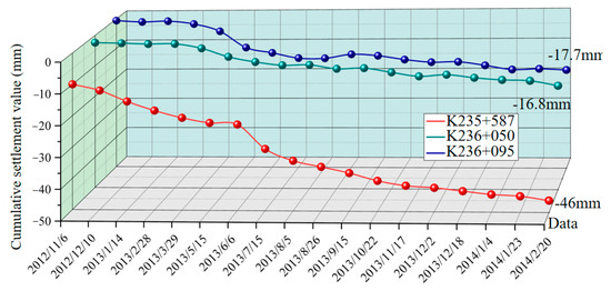
Figure 7.
Time-series monitoring data of K235 +587, K236 +050, and K236 +095 position.
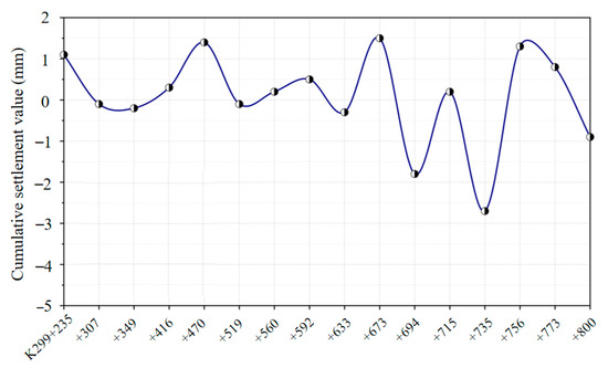
Figure 8.
Monitoring data of accumulated settlement along sections K299 +235 to K299 +800.
To explain the consistent emergence of track geometry irregularity at the mileage point, K298 is difficult, while the deformation of the subgrade at this point is almost imperceptible. Therefore, we used the GPR technique to investigate this cause. The image of GPR showed that the reflected signals of the subgrade section were relatively weak from K299 +680 to +750, indicating disruption of the lower soil layer (Figure 9a). The field investigation showed that the slope toe of the subgrade was destroyed due to the construction of metro line 3, resulting in the tendency of the subgrade to incline to the outer side. The cause of subgrade defects in mileage point K235 was also investigated in detail using the GPR technique. The GPR image demonstrates distinct low reflection areas in contrast with the surrounding region at the bottom of the subgrade of this section (Figure 8). Since the subgrade is layered filling and compaction, thus the signal of each subgrade layer is represented as a layered texture on the GPR image. The upper part of the subgrade was well structured, but the lower part was degraded in sections K235 +540 to +680 (Figure 9b). The onsite investigation discovered that this location is close to the Yangtze River. An infiltrated surface and the outward hydraulic gradient after a rapid drop in water level would be formed during the dry season (November to April of next year). Consequently, soil particles were washed away from the subgrade due to seepage forces. This erosion phenomenon will damage soil structure (Figure 9b) and aggravate the consolidation of soil under the additional stress of high-speed trains. This was the cause of a significant increase in subgrade deformation of this section after 11 December 2012 (Figure 6).
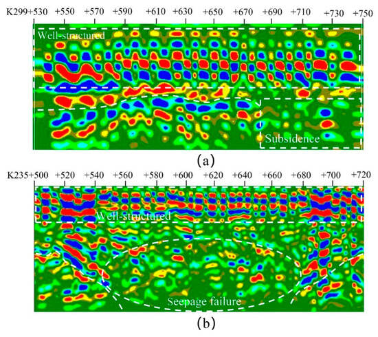
Figure 9.
Ground-penetrating radar (GRP) scanning results for the sections of K235 and K299. (a) and (b) are GPR images of subgrade structures at K299 and K235, respectively, all GPR imges was obtained from Shanghai Railway Bureau.
In summary, it is concluded that the sections from K235 +540 to +680 and K299 +680 to +750 have been finally identified as subgrade defects using GRP. The subgrade structures at K235 and K299 are deteriorated, leading to varying degrees of deformation caused by groundwater fluctuations and human activities, respectively.
6. Discussions and Future Work
The subgrade is vulnerable to climatic and geological factors, human activities, and long-term train load. The deformation or defect is more likely to appear in the subgrade section. However, the defect of the subgrade is imperceptible because it is covered by a closed waterproof sealing structure. The detailed investigation and treatment of health status or defects of subgrade are the critical factors for ensuring the safe and smooth operation of the train. Thus, an efficient, economical, and promising method is expected to be developed to explore the potential defect in all railway mileage. To obtain detailed information on subgrade defects, it is necessary to investigate the factors that may affect the high-speed railway line. Therefore, three monitoring works should be carried out to the health status or defects of subgrade:
First, geologic hazards (e.g., land subsidence) will directly affect the stability of subgrade structures. The uneven settlement of the ground is vulnerable to the overexploitation of groundwater and the construction of metro and high-rise buildings. The subgrade near the river is more susceptible to water level fluctuation, just like the subgrade is being inundated by rising waters, causing decreases in strength and bearing capacity. The secondary consolidation settlement is caused by pore water pressure dissipation inside the subgrade after falling water level. As illustrated in this work, the D–InSAR technique can effectively capture regional ground deformation. Consequently, the K235 and K298~K300 sections severely affected by the land subsidence are roughly determined in this work.
Second, the state of railway infrastructure cannot be precisely measured using InSAR alone. Therefore, track geometry measurement is employed to locate the potential defect areas. Irregularities caused by minor deformations at the subgrade–bridge transition section and track deviation should be excluded by analyzing the time-series TQI data because those defects can be repaired by tamping devices or chemical grouting techniques. The combined results of the InSAR and TQI allow for the precise identification and reaffirmation of potential defect locations along the railway line. This study has highlighted that the mileage points at K235, K236, K237, and K299 are identified as potential defect mileage points. In addition, the detailed sites and defect causes should be investigated in the next step.
Third, deformation monitoring and detailed defect information for infrastructure are carried out by leveling and GPR technology, respectively. The excessive deformation can directly indicate that the subgrade structure has been severely damaged. The specific location of the defect can be determined by the high-accuracy measuring capability of the CPIII control network. The settlement monitoring of the infrastructure in mileage point K237 rules out the possibility of this position being affected by subgrade defects. Finally, K235, K236, and K299 are identified as subgrade defects. The GPR is used to survey the causes of defects and their development trends, and it possesses a function similar to “computed tomography (CT)” scanning in the medical field. GPR can identify shallow cavities, the depth of the water table, potential deformation inside the subgrade, and even the slip surface. Some of the contributions of GPR have been proved for the identification of defects at part of the K235 and K299 mileage points.
In conclusion, a novel “integrated” approach is presented to investigate railway subgrade defects in detail utilizing remote sensing, train measuring systems, and non-destructive techniques (Figure 10). The multisource, multiscale, and multitemporal information is collected by combining InSAR, TQI, precision leveling, and GPR techniques, encompassing the aerial, train-mounted, and ground-based platforms. A collaborative analysis method of multisource data is employed to find the target areas from large-scale ground subsidence and small-scale infrastructure status information. A case study of SNHR demonstrates that the proposed method can accurately identify the health status and locate defects in the subgrade. It can also quantitatively assess the development trends of defects and can provide suggestions for maintenance plans based on the service status of subgrade and threat degree of defects.
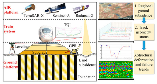
Figure 10.
Integration of air, train system, and ground platform for identifying the potential subgrade defect.
In current practice, the monitoring of subgrade health status typically relies on one or two methods, including GPS, leveling, GPR, and InSAR, as well as the comprehensive inspection train [39,40,41]. For example, GPS can automatically capture long-term deformation information of the subgrade at specific locations, but it is very costly. However, the monitoring accuracy of these techniques depends on the transmission signal. In cases where there are obstructions from tall buildings, trees, or adverse weather conditions, the accuracy of deformation monitoring results may be compromised [42]. Traditional settlement monitoring methods can provide highly accurate deformation information, and GPR can assess the health status of the subgrade. However, these methods are quite time-consuming [43,44] and impractical for covering the whole subgrade. InSAR and comprehensive inspection trains boast their advantages in extensive coverage, yet the monitoring accuracy of both these methods tends to be relatively low [11,19].
In summary, depending solely on the sensitivity of the single monitoring method may result in blind spots or areas that are not being adequately monitored. Furthermore, a single monitoring method may only be able to detect one or a few of these types of degradation, missing the signs of others. In addition, some monitoring techniques are more susceptible to external factors such as weather conditions, traffic loads, or nearby construction activities. These factors collectively indicate that one or two monitoring methods alone cannot serve as a comprehensive solution for detecting defects covering the whole subgrade. Therefore, the “integrated” monitoring approach for subgrade defects in this work leverages the advantages of various monitoring techniques, allowing for cross-validation of the monitoring results. This approach enhances the accuracy and efficiency of subgrade defect detection.
However, the limitation of the study is that the land subsidence is determined using InSAR images for a relatively short period, ranging from August 2010 to November 2010, due to the unavailability of free InSAR data for the period from 2011 to 2014 [45]. This problem was solved after the Sentinel–1A satellite launched in April 2014. The Sentinel–1A images with high temporal resolution and a short revisiting period (12 d) can be adopted for frequent ground acquisitions in regional areas. Furthermore, the integration of multisensor SAR images will enable the high-precision and short-term monitoring of deformation along the railway with the increasing number of satellites and the availability of open data in the future.
7. Conclusions
The requirements for the safe operation and detection/monitoring of infrastructure deterioration are becoming higher due to the sustained growth of total railway mileage. However, adverse natural and environmental disasters jeopardize the sustainability of the railway network, which increases the probability of potential risks during high-speed train operations. Recent advancements in monitoring technology have made it possible to quickly survey and monitor subgrade health. This study provides a comprehensive overview of the primary methods employed for monitoring and detecting railway defects and deformation, and it also draws attention to the monitoring objects and “integrated” holistic monitoring technique for high-speed railway subgrade. The defect location, deformation trend, and the cause of deterioration are investigated in detail in SNHR. The procedure of this integrated method and the deficiency are discussed. The following conclusions are suggested:
First, the monitoring content of subgrade service status should contain the environmental and geological hazards that threaten the subgrade (e.g., land subsidence triggered by overexploitation of groundwater and engineering activities), track geometry status, deformation monitoring, and internal defect of the subgrade. An “integrated” holistic monitoring technique is carried out through the general investigation (locating the potential defects using InSAR and TQI), detailed surveys (long-term deformation monitoring by leveling), and exploration (defects diagnosis using GPR).
Second, the result of the D–InSAR method indicates that the K235 and K298~K300 sections of SNHR are severely affected by land subsidence. Time-series TQI data are combined to reconfirm the location of the potential defect area further. Subsequently, the local areas of the subgrade mileage points K235 and K299, as well as the bridge–subgrade transition mileage points K236 and K237, are estimated as the potential defect positions based on the frequency of TQI exceeding the threshold and settlement monitoring.
Third, the settlement monitoring data along the critical areas demonstrates that the settlement at K235 +587, K236 +050, and K236 +095 exceed the standard value of the deformation for high-speed railways. The maximum values of subgrade settlement are −46, −17.7, and −16.8 mm in these locations, respectively. Furthermore, the possibility of subgrade deterioration is excluded in the K237 mileage point (settlement not exceeding 15 mm). The differential settlement is identified as the main cause of track irregularities in the bridge–subgrade transition mileage point K237. Finally, the K235, K236, and K299 points are estimated as subgrade defects by cooperative analysis of INSAR, TQI, and settlement.
Fourth, the GPR technique is used to survey the health status at K235 and K299 mileage points. It is revealed that the lower part of the subgrade structure for K235 +540 to +680 deteriorated due to the influence of seepage failure caused by a rapid drop in water level and train dynamic load. Additionally, the lower soil layer of the subgrade is disrupted at K299 +680 to +750 due to the deformation of the toe triggered by engineering activity.
Fifth, this study has demonstrated that an “integrated” holistic monitoring technique can provide more comprehensive information on subgrade service status at different spatiotemporal scales. This technique can be more useful in the accurate identification of defects, development of maintenance plans, and effective implementation of fault recovery of railway infrastructure. Furthermore, this technique will continue to be improved with the increasing number of satellites and enhancement of Earth-observation capability.
Author Contributions
Conceptualization, Y.L. and Y.H.; software, Y.L.; validation, Y.H.; writing—original draft preparation, Y.L.; writing—review and editing, Y.L. and Y.H. supervision, L.X.; funding acquisition, L.X. All authors have read and agreed to the published version of the manuscript.
Funding
This work was funded by the National Natural Science Foundation of China (Grant Nos. U2268213, 42172322, and 42007419), National Key Research and Development Program of China (Grant No. 2018YFC1505403), Natural Sciences Funding Project of Hunan Province (Grant No. 2020JJ5981), Excellent Youth Fund Project of Hunan Provincial Education Department (21B0226), and the China Railway Group Limited Technology Research and Development Plan (2022—key program-01).
Data Availability Statement
The data are not publicly available due to confidentiality requirements.
Acknowledgments
We are grateful to ASF (Alaska Satellite Facility) and NASA (National Aeronautics and Space Administration) for providing the InSAR and DEM data.
Conflicts of Interest
The authors declare no conflicts of interest.
References
- National Railway Administration of the People’s Republic of China (NRAPR). Statistics of China’s High-Speed Railway Operating Mileage. 2023. Available online: http://www.nra.gov.cn/wef/zxkn/202301/t20230104_339423.shtml (accessed on 4 January 2023).
- National Railway Administration of the People’s Republic of China (NRAPR), Announcement on Investigation of Major Railway Traffic Accidents. Available online: http://www.nra.gov.cn/zzjg/jgj/gzgl/gsgz (accessed on 30 April 2020).
- Li, M.; Persson, I.; Spännar, J.; Berg, M. On the use of second-order derivatives of track irregularity for assessing vertical track geometry quality. Veh. Syst. Dyn. 2012, 50, 389–401. [Google Scholar] [CrossRef]
- Xu, L.; Zhai, W. A novel model for determining the amplitude-wavelength limits of track irregularities accompanied by a reliability assessment in railway vehicle-track dynamics. Mech. Syst. Signal Proc. 2017, 86, 260–277. [Google Scholar] [CrossRef]
- Sadeghi, J. Development of railway track geometry indexes based on statistical distribution of geometry data. J. Transp. Eng. 2010, 136, 693–700. [Google Scholar] [CrossRef]
- Lasisi, A.; Attoh-Okine, N. An unsupervised learning framework for track quality index and safety. J. Transp. Eng. 2020, 7, 1–12. [Google Scholar] [CrossRef]
- Lasisi, A.; Attoh-Okine, N. Principal components analysis and track quality index: A machine learning approach. Transp. Res. Pt. C-Emerg. Technol. 2018, 91, 230–248. [Google Scholar] [CrossRef]
- Madejski, J.; Grabczyk, J. Continuous geometry measurement for diagnostics of tracks and switches. In Proceedings of the International Conference on Switches; Delft University of Technology: Delft, The Netherlands, 2002. [Google Scholar]
- Liu, R.K.; Xu, P.; Sun, Z.Z.; Zou, C.; Sun, Q.X. Establishment of track quality index standard recommendations for Beijing metro. Discret. Dyn. Nat. Soc. 2015, 2015, 473830. [Google Scholar] [CrossRef]
- Lu, C.; Cai, C. Overview on safety management and maintenance of high-speed railway in China. Transp. Geotech. 2020, 25, 100397. [Google Scholar] [CrossRef]
- Čebašek, T.M.; Esen, A.F.; Woodward, P.K.; Laghrouche, O.; Connolly, D.P. Full scale laboratory testing of ballast and concrete slab tracks under phased cyclic loading. Transp. Geotech. 2018, 17, 33–40. [Google Scholar] [CrossRef]
- Li, S.; Xu, W.; Li, Z. Review of the SBAS InSAR Time-series algorithms, applications, and challenges. J. Geod. Geodyn. 2022, 13, 114–126. [Google Scholar] [CrossRef]
- Liu, C.; Li, N.; Wu, H.; Meng, X. Detection of high-speed railway subsidence and geometry irregularity using terrestrial laser scanning. J. Surv. Eng. 2014, 140, 04014009. [Google Scholar] [CrossRef]
- Chen, H.; He, J.; Xue, Y.; Zhang, S. Experimental study on sinkhole collapse monitoring based on distributed Brillouin optical fiber sensor. Optik 2020, 216, 164825. [Google Scholar] [CrossRef]
- Xing, X.; Chang, H.C.; Chen, L.; Zhang, J.; Yuan, Z.; Shi, Z. Radar interferometry time series to investigate deformation of soft clay subgrade settlement—A case study of Lungui Highway, China. Remote Sens. 2019, 11, 429. [Google Scholar] [CrossRef]
- Chen, B.; Gong, H.; Chen, Y.; Lei, K.; Zhou, C.; Si, Y.; Li, X.; Pan, Y.; Gao, M. Investigating land subsidence and its causes along Beijing high-speed railway using multi-platform InSAR and a maximum entropy model. Int. J. Appl. Earth Obs. Geoinf. 2021, 96, 102284. [Google Scholar] [CrossRef]
- Gutiérrez, F.; Galve, J.P.; Lucha, P.; Castañeda, B.; Bonachea, J.; Guerrero, J. Integrating geomorphological mapping, trenching, InSAR and GPR for the identification and characterization of sinkholes: A review and application in the mantled evaporite karst of the Ebro Valley (NE Spain). Geomorphology 2011, 134, 144–156. [Google Scholar] [CrossRef]
- Wang, L.; Deng, K.; Zheng, M. Research on ground deformation monitoring method in mining areas using the probability integral model fusion D-InSAR, sub-band InSAR and offset-tracking. Int. J. Appl. Earth Obs. Geoinf. 2020, 85, 101981. [Google Scholar] [CrossRef]
- Dheenathayalan, P.; Small, D.; Schubert, A. High-precision positioning of radar scatterers. J. Geodesy. 2016, 90, 403–422. [Google Scholar] [CrossRef]
- Wang, R.; Yang, M.; Dong, J.; Liao, M. Investigating deformation along metro lines in coastal cities considering different structures with InSAR and SBM analyses. Int. J. Appl. Earth Obs. Geoinf. 2022, 115, 103099. [Google Scholar] [CrossRef]
- Suo, Z.; Zhang, J.; Li, M.; Zhang, Q.; Fang, C. Improved InSAR phase noise filter in frequency domain. IEEE Trans. Geosci. Remote Sens. 2015, 54, 1185–1195. [Google Scholar] [CrossRef]
- Jung, J.; Kim, D.; Lavalle, M.; Yun, S. Coherent change detection using InSAR temporal decorrelation model: A case study for volcanic ash detection. IEEE Trans. Geosci. Remote Sens. 2016, 54, 5765–5775. [Google Scholar] [CrossRef]
- Bai, M.; Chen, Y.; Wang, C.; Li, X.; Tian, G. Radar spectral analysis and evaluation of the effect of grouting treatment in karst caves and soil caves. Environ. Earth Sci. 2018, 77, 795. [Google Scholar] [CrossRef]
- Fontul, S.; Paixão, A.; Solla, M.; Pajewski, L. Railway track condition assessment at network level by frequency domain analysis of GPR data. Remote Sens. 2018, 10, 559. [Google Scholar] [CrossRef]
- Dzurisin, D. A comprehensive approach to monitoring volcano deformation as a window on the eruption cycle. Rev Geophys. 2003, 41. [Google Scholar] [CrossRef]
- Andronico, D.; Spinetti, C.; Cristaldi, A.; Buongiorno, M.F. Observations of Mt. Etna volcanic ash plumes in 2006: An integrated approach from ground-based and polar satellite NOAA–AVHRR monitoring system. J. Volcanol. Geotherm. Res. 2009, 180, 135–147. [Google Scholar] [CrossRef]
- Allison, R.S.; Johnston, J.M.; Craig, G.; Sion, J. Airborne optical and thermal remote sensing for wildfire detection and monitoring. Sensors 2016, 16, 1310. [Google Scholar] [CrossRef] [PubMed]
- Hua, L.; Shao, G. The progress of operational forest fire monitoring with infrared remote sensing. J. For. Res. 2017, 28, 215–229. [Google Scholar] [CrossRef]
- Dai, K.; Li, Z.; Xu, Q.; Bürgmann, R.; Milledge, D.; Tomás, R.; Fan, X.; Zhao, C.; Liu, X. Entering the era of earth observation-based landslide warning systems: A novel and exciting framework. IEEE Geosci. Remote Sens. Mag. 2020, 8, 136–153. [Google Scholar] [CrossRef]
- Lei, T.; Wang, J.; Li, X.; Wang, W.; Shao, C.; Liu, B. Flood Disaster Monitoring and Emergency Assessment Based on Multi-Source Remote Sensing Observations. Water 2022, 14, 2207. [Google Scholar] [CrossRef]
- Hu, Q.; Ma, R.; Chen, F.; Jiang, A.; Wang, Y. Urban landscape monitoring based on high-resolution spaceborne TerraSAR-X data: A case study of Nanjing City, China. Remote Sens. Lett. 2018, 9, 447–456. [Google Scholar] [CrossRef]
- Lin, P.; Chen, X.; Jiang, M.; Song, X.; Xu, M.; Huang, S. Mapping shear strength and compressibility of soft soils with artificial neural networks. Eng. Geol. 2022, 300, 106585. [Google Scholar] [CrossRef]
- Xiao, Y.; Shi, C. On the Division of the Quaternary in the Nanjing region, Eastern China. J. Nantong Univ. (Nat. Sci. Ed.) 2008, 7, 60–65. (In Chinese) [Google Scholar]
- Liu, L.; Cai, G.; Liu, S.; Chen, Y. Deformation characteristics and control for foundation pits in floodplain areas of Nanjing, China. Bull. Eng. Geol. Environ. 2021, 80, 5527–5538. [Google Scholar] [CrossRef]
- Zebker, H.A.; Rosen, P.A.; Hensley, S. Atmospheric effects in interferometric synthetic aperture radar surface deformation and topographic maps. J. Geophys. Res.-Solid Earth 1997, 102, 7547–7563. [Google Scholar] [CrossRef]
- Zhang, B.; Li, J.; Ren, H. Using phase unwrapping methods to apply D-InSAR in mining areas. Can. J. Remote Sens. 2019, 45, 225–233. [Google Scholar] [CrossRef]
- Xu, X.J.; Lei, Y.; Yang, F. Railway Subgrade Defect Automatic Recognition Method Based on Improved Faster R-CNN. Sci. Program. 2018, 2018, 4832972. [Google Scholar] [CrossRef]
- Zhao, Y.; Zhou, L.; Wang, C.; Li, J.; Qin, J.; Sheng, H.; Huang, L.; Li, X. Analysis of the spatial and temporal evolution of land subsidence in Wuhan, China from 2017 to 2021. Remote Sens. 2022, 14, 3142. [Google Scholar] [CrossRef]
- Silvast, M.; Nurmikolu, A.; Wiljanen, B.; Levomäki, M. Identifying frost-susceptible areas on Finnish railways using the ground penetrating radar technique. Proc. Inst. Mech. Eng. Part F J. Rail Rapid Transit 2013, 227, 3–9. [Google Scholar] [CrossRef]
- Jia, C.; Yang, X.; Wu, J.; Ding, P.; Bian, C. Monitoring analysis and numerical simulation of the land subsidence in linear engineering areas. KSCE J. Civ. Eng. 2021, 25, 2674–2689. [Google Scholar] [CrossRef]
- Hou, Z.; Zhao, W.; Yang, Y. Identification of railway subgrade defects based on ground penetrating radar. Sci. Rep. 2023, 13, 6030. [Google Scholar] [CrossRef] [PubMed]
- Schipperijn, J.; Kerr, J.; Duncan, S.; Madsen, T.; Klinker, C.D.; Troelsen, J. Dynamic accuracy of GPS receivers for use in health research: A novel method to assess GPS accuracy in real-world settings. Front. Public Health 2014, 2, 21. [Google Scholar] [CrossRef] [PubMed]
- Xu, J.; Li, X.; Yang, J.; Gao, Y.; Wu, S. A remote subgrade settlement monitoring system based on optical method. Urban Rail Transit 2019, 5, 202–206. [Google Scholar] [CrossRef]
- Elseicy, A.; Alonso-Díaz, A.; Solla, M.; Rasol, M.; Santos-Assunçao, S. Combined use of GPR and other NDTs for road pavement assessment: An overview. Remote Sens. 2022, 14, 4336. [Google Scholar] [CrossRef]
- Li, G.; Yang, F.; Ke, Z.; Sun, X.F.; Liu, B.; Zhao, W.; Zhou, Y. Long-Term Monitoring of Local Track Irregularity and Its Influence for Simply Supported Girder Bridge of HSR. Buildings 2022, 12, 445. [Google Scholar] [CrossRef]
Disclaimer/Publisher’s Note: The statements, opinions and data contained in all publications are solely those of the individual author(s) and contributor(s) and not of MDPI and/or the editor(s). MDPI and/or the editor(s) disclaim responsibility for any injury to people or property resulting from any ideas, methods, instructions or products referred to in the content. |
© 2024 by the authors. Licensee MDPI, Basel, Switzerland. This article is an open access article distributed under the terms and conditions of the Creative Commons Attribution (CC BY) license (https://creativecommons.org/licenses/by/4.0/).