Abstract
Accurate estimates of tropical cyclone (TC) intensity are important for improving forecasts as well as studying ocean dynamics during such extreme events. Since most cyclone life occurs over the open ocean, remote sensing techniques play an important role in obtaining the necessary data. The possibility of using the configuration of spiral signatures of mature tropical cyclones (TCs) observed in synthetic aperture radar (SAR) images to estimate the maximum wind speed of a TC is considered. This study assessed the intensity of 14 TCs in the Atlantic and Pacific Oceans using radar images obtained by the Radarsat Hurricane Application Project. TC intensity was estimated using the hyperbolic-logarithmic approximation of TC spiral signatures (HLS approximation). Additionally, the edges of the spiral signatures were partially fitted using a logarithmic spiral to improve the reliability of the HLS approximation. For the first time, a physical model of changing the crossing angle of the logarithmic portion of the edges was proposed and tested on SAR images of the TC. HLS maximum wind speed estimates were compared with Best Track estimates. The results showed the closeness of both estimates with a correlation of 0.95 and a standard deviation of 2.9 m s−1. The results indicate the possibility of using the HLS approximation to estimate the intensity of mature TCs from SAR data.
1. Introduction
Ocean dynamics plays an important role in understanding the distribution of heat, biological and chemical species in the ocean and the interaction of the water surface with the atmosphere [1]. Tropical cyclones (TCs) are one of the natural strong and large-scale factors that intensify this process due to their significant influence on disturbances of the sea surface and atmosphere. The main dynamic parameter that determines the impact of a cyclone on the environment is its intensity. Since most of the TC life cycle occurs over the ocean, remote sensing of TC intensity is an important task in satellite remote sensing. Spaceborne synthetic aperture radar (SAR) is considered a suitable remote sensing tool for obtaining information on the intensity of TCs due to its sensitivity to sea surface roughness, ability to partially penetrate the cloud-rain field (CRF) accompanying TCs, and independence from solar radiation [2]. The key features of the SAR sounding follow from the phenomenological model of the normalized radar cross-section (NRCS, σ0) of the TC region, based on information provided in [3,4]:
where σwind and σsrf are backscatter from the sea surface caused by wind-induced and rain-induced perturbations, respectively; L(r) is the dimensionless integral attenuation coefficient, h is the slant range from the sea surface to bottom layer of the CRF (, θ is the radar incidence angle), H is the slant height of CRF top layer (, H0 is the altitude of CRF top layer); L = L(0); , is a coefficient related to the absorption properties of water, where m is the complex refractive index of water; λ is the radar wavelength (cm); Ze is the effective reflectivity (mm6 m−3) of CRF. In this model, SAR rainband signatures are a combination of bright and dark elements (compared to the background image) organized in a spiral shape and caused by the following physical mechanisms [5]:
- Attenuation due to heavy rain;
- Backscattering from raindrops in the air and ice particles;
- Sea-surface capillary waves induced by rain;
- Damping of sea surface waves by rain-induced turbulence;
- Wind gusts.
Currently, most methods for determining wind speed from SAR data and estimating the NRCS wind component (σwind) are based on the empirical relationship between sea surface backscatter and near-surface wind [6]. A short review of these studies up to 2013 can be found in [5]. However, according to the model (Equation (1)), the backscatter from the wind component is “contaminated” by backscatter due to the contribution of other factors, in particular CRF, where precipitation makes the largest contribution. In addition, for high winds over 20–25 m s−1, the 0.5–1.0 dB SAR calibration errors induce large wind retrieval errors owing to the saturation of this SAR component [7]. To mitigate these interfering factors, the contribution of precipitation was assessed using passive microwave observations of rain in combination with geostationary IR images and SAR image features of TC [4].
The SAR wind speed retrieval accuracy of backscattering measurements is also affected by errors in the estimated wind directions and radar incidence angle. To mitigate this contribution and extend the range of measurable speeds to high wind speeds during severe storms, the cross-polarized NRCS should be measured [8]. Another method uses combined airborne L-band passive microwave measurements from the Soil Moisture Active and Passive Mission and Stepped Frequency Microwave Radiometer (SFMR) measurements, which are less sensitive to precipitation [9]. Articles [9,10,11,12] demonstrated how combined co- and cross-polarization C-band SAR measurements efficiently resolve TC inner-core wind field characteristics based on specific empirical geophysical model functions (GMFs). However, the physical relationship between the wind vector and its radar backscatter is a complex nonlinear function that, in addition to (1), also includes the polarization and relative azimuth between the radar viewing angle and the wind direction. To increase the efficiency of solving the inverse GMF problems, reconstruct the entire TC structure, and enhance the low-quality data, neural network technologies and machine learning methods are used [13,14].
In general, all modern methods for obtaining information about wind in TCs from space-based SAR are based on the dependence of backscatter on the modification of the sea surface caused by the surface wind. This dependence is described, as noted above, using GMFs adapted to a specific radar sensing mode. The most confounding factors in these methods are the effect of rain on backscatter, inaccuracy in estimating wind direction, and “saturation” of the backscatter in high winds, which are mitigated by the use of additional information from other sensors or by the use of dual-polarized SAR.
This study proposes a method for estimating maximum wind speed (MWS) in TCs from SAR images that does not use the backscatter magnitude as a measure of wind speed. The method is based on measuring the characteristics of the configuration of spiral (arc) bands, which are one of the most pertinent features of SAR images of TCs. These bands are caused by spiral cloud-rain bands (SCRBs) and near-surface winds disturbing the sea surface. SCRB spiral signatures and their individual elements in SAR images can be brighter or darker than the reflection from the surrounding sea surface, depending on the ratio of the components in Equation (1). The orientation of SCRB, which is revealed in the radar and satellite images of TCs, occurs predominantly along streamlines in a hurricane [15,16]. Using the known distribution of forces in a cyclone and representing the cyclone as a Rankine vortex, the analytical expression for the streamline configuration is in the form of the Hyperbolic-Logarithmic spiral (HLS) [17,18], where its parameters depend on maximum wind speed. Articles [19,20] also showed, by providing several examples of satellite and radar images of TCs, that the spiral signatures are satisfactorily approximated by the HLS. The intensities of several cyclones have been estimated using calculated HLS parameters. These estimates were close to the results of both aircraft measurements and Best Track data, including the estimates of the most common empirical method of Dvorac [21,22]. In the current study, further improvement of the method was achieved by measuring and using the crossing angle (more precisely, its tangent) of the logarithmic portion of the trailing and leading edges of the spiral signatures.
In contrast to the empirical SAR backscatter methods mentioned above, this work aims to develop a method for estimating TC intensity based on a physical streamline model (HLS). This method exploits the configuration parameters of cloud-rain spiral signatures in SAR images as a source of information on the MWS. In contrast to backscatter methods, the rain factor delineating the configuration of spiral signatures is favorable for determining TC intensity in the HLS approach. The difference between the surface wind direction and the SAR sounding does not affect the HLS estimate of the MWS. Therefore, this study applies the HLS approximation to the spiral SAR signature to estimate the TC intensity.
Descriptions of the Data acquisition and processing, including the dataset and the essence of the HLS assessment method, are presented in Section 2. Section 3 presents the results of the HLS approximation of spiral signatures and a comparison of the obtained maximum wind speeds with the best Track data. Discussion and conclusions are presented in Section 4 and Section 5, respectively.
2. Data Acquisition and Processing
2.1. Composition of the Dataset
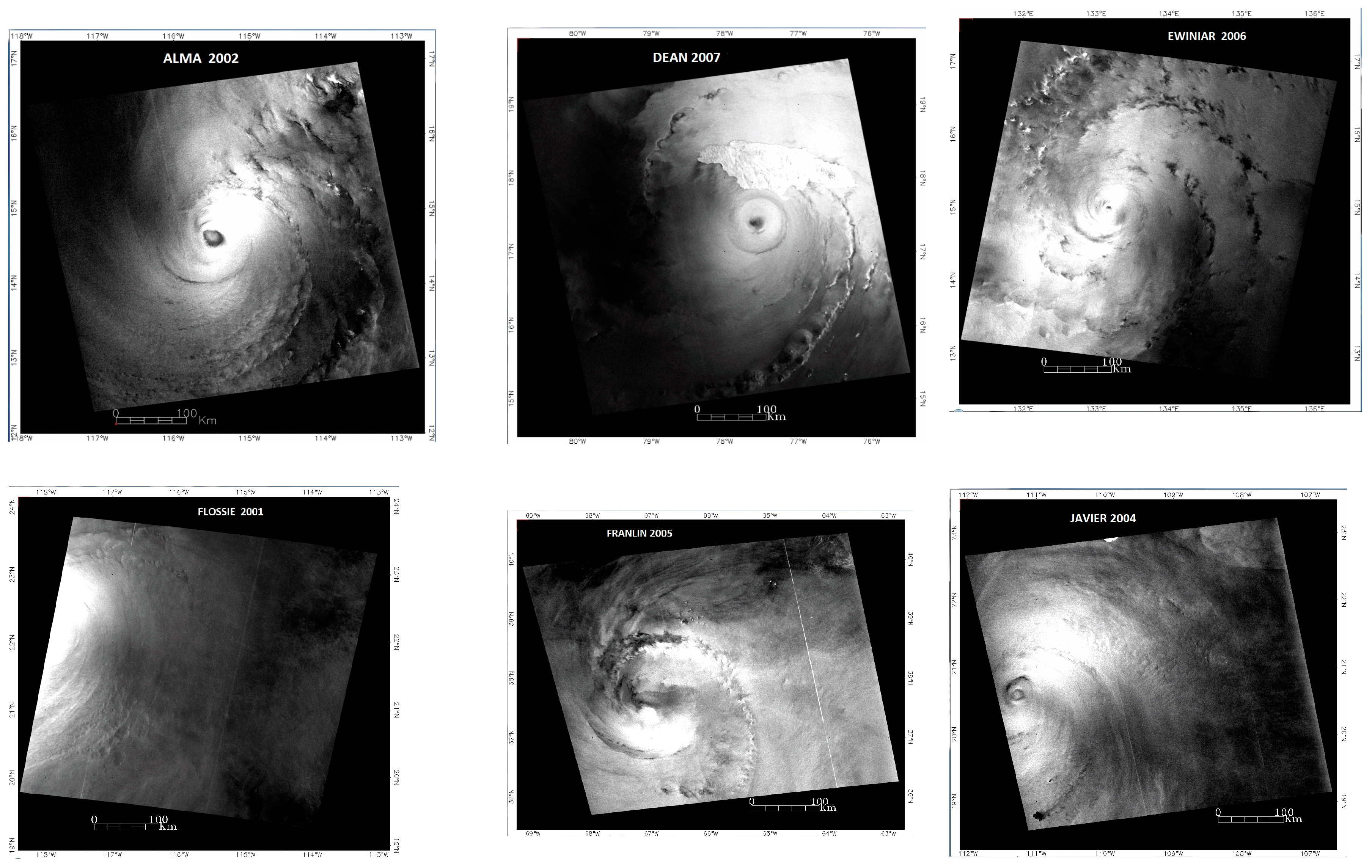
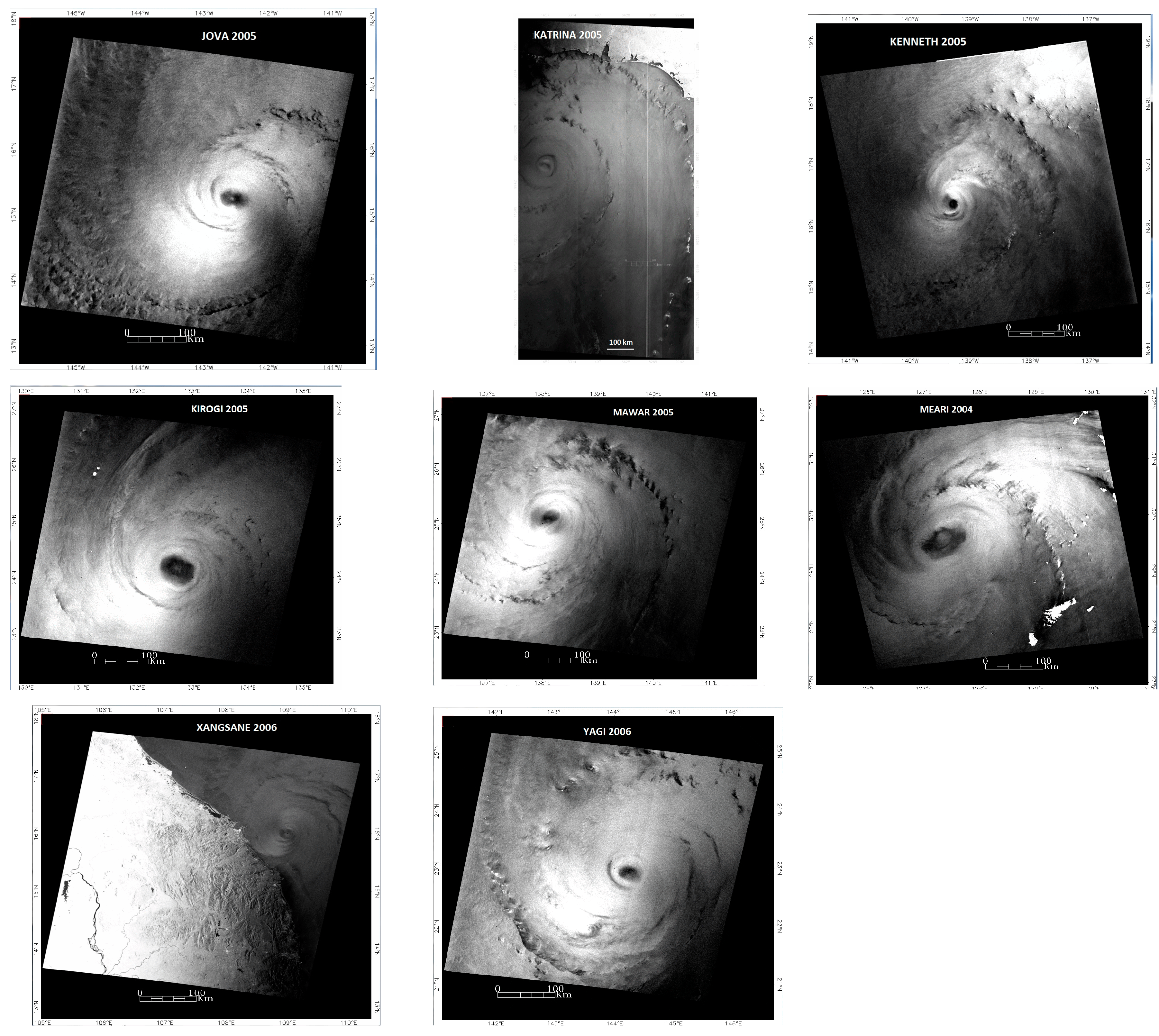
The RadarSAT-1 data set provided by the Center for Advanced Remote Sensing for the Southeast Tropical Regions (CSTARS) under the Radarsat Hurricane Application Project (RHAP) for the years 2002–2007 was examined. Only SAR images with a clearly defined spiral structure are suitable for the HLS approximation. Due to these requirements, 14 images from the 144 available hurricanes within the RHAP dataset were selected for processing. All of them were acquired by the Radarsat-1 satellite over the Atlantic Ocean, as well as the western and eastern parts of the Pacific Ocean. Table 1 lists these TCs. The analyzed spiral bands belonged predominantly to the inner region of the cyclones at a distance of no more than 250 km from the center of the TC.

Table 1.
List of TCs processed using the HLS approximation in this study.
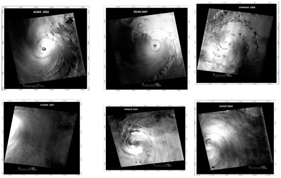
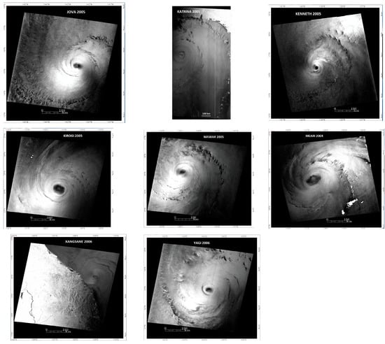
Figure 1.
SAR images of tropical cyclones used in the study.
2.2. The Essence of the HLS Assessment
2.2.1. Dependence of the Maximum Wind Speed on HLS Parameters
The essence of the HLS assessment of the MWS is as follows. The assessment used the hyperbolic distribution of the tangential velocity in the outer part of the Rankine vortex.
where R is the polar radius in the center of the cyclone, Rm is the radius of the maximum wind (MWR) relative to which the vortex region is divided into internal and outer parts, Vm is the maximum wind speed (MWS), V(R) is the wind speed at a distance R from the center of the cyclone, n is the hyperbolic index. It is shown in [17,18] that a streamline forming the rainband for the outer section of the Rankine vortex is described by the HLS in polar coordinates, originating at the center of the TC:
where φ is the polar angle, y = R/R0 is the polar radius normalized to R0 that is the conditional range of the beginning of a streamline that coincides with the range of the accepted reference point of the polar angle of the spiral (a point within a spiral signature), ym = Rm/R0 is the relative radius of maximum wind speed. Since lny ≤ 0 over the entire range of the changes in the polar angle, it is reasonable to represent the Equation (3) as a function of the module of the natural logarithm of the relative polar radius (i.e., |lny|):
This form of notation allows omitting the minus sign for lny and thereby simplifying the graphical representation of the spiral in convenient positive semi-logarithmic coordinates. Coefficients A and B are determined by the following relationships:
and
where k is the friction coefficient and f is the Coriolis parameter, can be called the Coriolis velocity. Thus, as follows from the definitions of the HLS coefficients (Equations (4) and (5)), the MWS can be determined for given n, f, Rm, and R0 as a function of approximate estimates of the coefficients and as follows:
2.2.2. Logarithmic Component of the HLS and the Crossing Angle
This work also draws attention to the distinct features of the spiral band, which are its edges, in order to find their contribution to improving the HLS estimate of TC intensity. When approximating SAR spiral bands, it was determined that some portions of trailing (closest to the center) and leading (farthest from the center) edges of the SAR signature, located outside the TC core, are well approximated by a logarithmic spiral: , where α is the crossing angle. According to [23,24,25], the crossing angle is the angle between the longitudinal axis of the band and the tangent to a circle whose radius is the distance from the band to the storm center. In the logarithmic form, the equation of the logarithmic spiral is
Logarithmic approximation is well known from studies of spiral bands of cloud and rain visible in radar and satellite images and is widely presented in the literature sources, summarized in several reviews [26,27]. The studies were focused on the investigation of the behavior of the crossing angle as an indicator of the degree of twisting of the spiral band. Since the logarithmic spiral is an equiangular spiral, the crossing angle should be a constant. However, based on the results of these studies, it was found that the crossing angle decreases as the intensity of the TC increases, and the observation point on the spiral approaches the center of the TC. Since these observed features indirectly indicate the dependence of the crossing angle on TC intensity, several possible explanations for the behavior of the crossing angle, as well as modifications of the logarithmic spiral, have been presented in these reviews and some recent studies [28,29,30]. However, the physical mechanisms behind these features still remain uncertain.
Taking into account the above, below is an analysis of the logarithmic portion of the edges of a spiral signature within the framework of the hyperbolic–logarithmic model used.
At first glance, the logarithmic component of the spiral is described only by the second term of Equation (4). However, the dependence of the crossing angle only on the B-factor, which, in turn, is determined by the friction coefficient (k) and the Coriolis parameter (f), does not explain the observed changes in the crossing angle listed above. In order to understand this issue, let us represent the exponential in the first term of Equation (4) in the form of a Maclaurin series:
As follows from this expansion, there is a term as a function of the first power of the logarithm of the relative radius (lny). Substituting the resulting expansion (9) into the original Equation (4) leads to the following:
where . Therefore, GHLS = 1/tan(α) is the full logarithmic component of the HLS, and its crossing angle is . Using an alternative form of coefficient A from (5), we obtain
From Expression (11), it follows that the crossing angle (more precisely, its tangent) of the logarithmic component of the hyperbolic–logarithmic spiral depends on several parameters, including the MWS. As follows from (11), the G-factor (and, consequently, the crossing angle or its tangent) can exhibit a dependence on the MWS only if the remaining parameters (B, n, ym, and VC) are constant, which can be expected during monitoring of an individual cyclone for a limited time. Changes in GHLS values can be caused by changes in cyclone intensity, as well as changes in MWR and hyperbolic index. The components B, n, and ym are found during the HLS approximation, and the Coriolis velocity is calculated from the known latitude of the TC center and the distance (R0) between the TC center and the position of the starting point of the spiral signature. The Vm-GHLS correlation is even less likely when comparing different cyclones (in this study) due to the non-synchronization of changes in the parameters included in (11). However, even in our case, checking the HLS estimates of parameters for compliance of their complex (11) with the G-factor turns out to be useful for the correct selection of their optimal values.
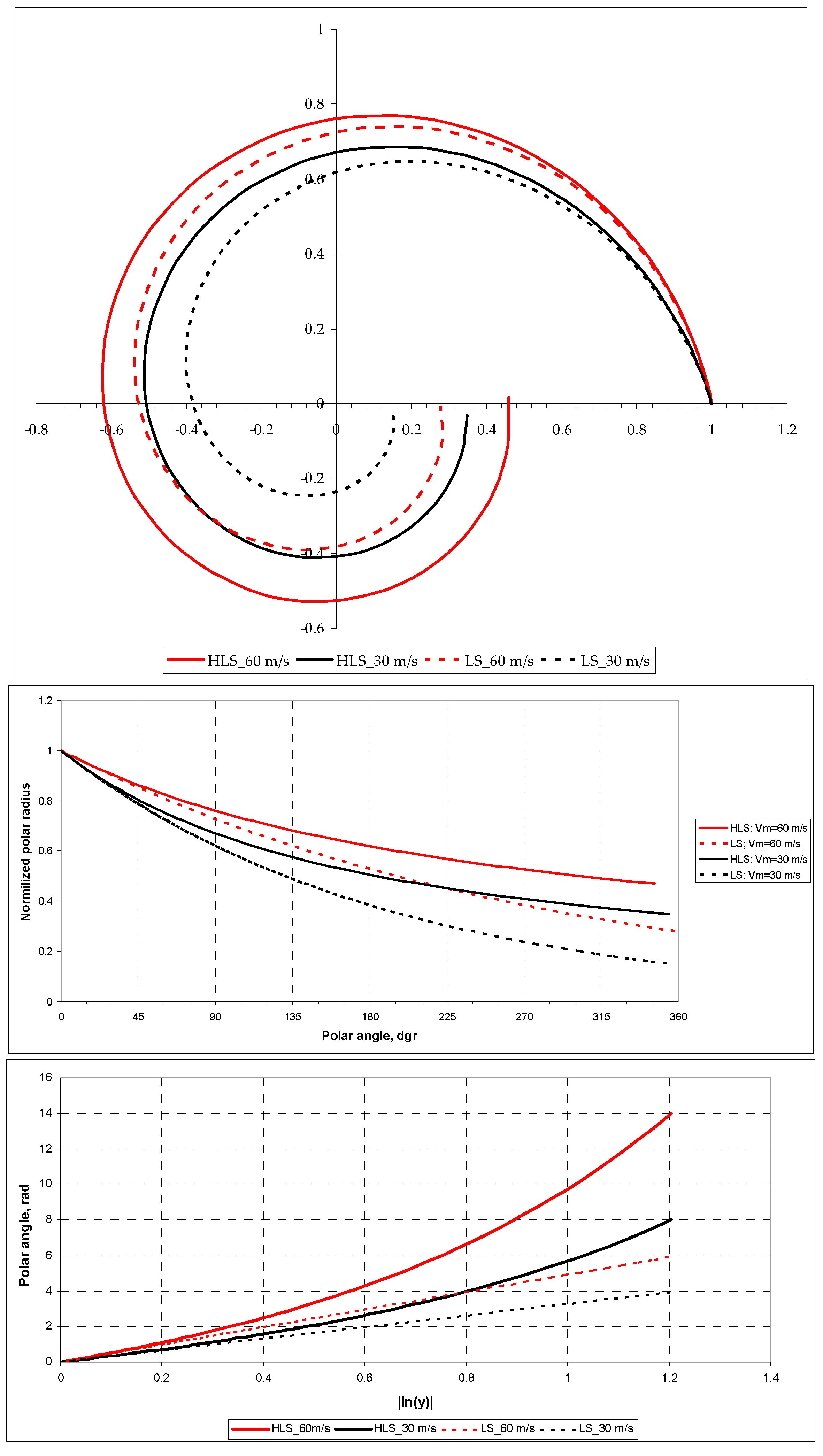
To illustrate the influence of MWS on the HLS configuration, Figure 2 shows two logarithmic spirals representing logarithmic components of the HLSs and two hyperbolic-logarithmic spirals corresponding to TCs with intensities 60 and 30 m s−1 at n = 0.6, f = 3.7735 × 10⁻⁵ s−1 (Latitude = 15°N), Rm = 2 × 10⁴ m, R0 = 2 × 10⁵ m, (ym = 0.1) and k = 2.3 × 10⁻⁵ s−1.
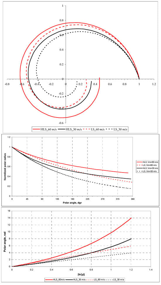
Figure 2.
Plots of model HLS and its logarithmic component (LS) for Vm = 30 m s−1 (black curves) and Vm = 60 m s−1 (red curves) in polar, rectangular, and semi-logarithmic coordinates (top, middle, and bottom panels, respectively); other information is in the text.
As follows from the presented graphs in the polar coordinate system, from a qualitative point of view, an increase in the intensity of the TC leads to a “rounding” of the HLS, which corresponds to the experimental data [11,15].
The plot in rectangular coordinates (middle panel) illustrates the greater contribution of the logarithmic component to the HLS (the minimal difference between the polar radii at a fixed polar angle) at the initial part of the curves within a sector of approximately 0°–90° and at higher Vm. For example, as follows from this graph, the difference in polar radii between the logarithmic component and the HLS at a polar angle of 90° is 5.3% for Vm = 60 m s−1 and 7.5% for Vm = 30 m s−1. For a polar angle of 180°, the difference is 14.5% for Vm = 60 m s−1 and 25.5% for Vm = 30 m s−1.
Logarithmic spiral plots in semi-logarithmic coordinates (bottom panel), represented by dashed straight lines, illustrate the dependence of logarithmic components on MWS. These components have an angle coefficient (tangent of the slope angle), which is the G-Factor. Higher wind speed increases the G-Factor (red dashed line), which, in turn, corresponds to a smaller crossing angle, and vice versa (black dashed line). This behavior is consistent with the experimental data presented in reviews [26,27]. In the model used as an example, GHLS = 3.28 and 4.92 for Vm = 30 m s−1 and 60 m s−1, respectively. This can be easily verified by making appropriate estimates of the tangent of the slope angle of the corresponding dashed lines at |lny| = 1.2. The corresponding crossing angles are 17° and 11.5°.
2.3. Data Processing (HLS Approximation)
The following is a brief description of the previously developed procedure for the assimilation approximation of the spiral band of a TC with a finite width [18,20]. The assimilation approximation is based on the assumption that cloudy rain particles trace wind streamlines and that their real trajectories can be replaced (assimilated) by hyperbolic-logarithmic spirals. The approximation consists of determining the spirals that “fit” into the geometric boundaries (edges) of the spiral band and calculating the “mean HLS” from their set. The fit spirals are defined as “signature” spirals. Coefficients A and B of signature spirals are determined by different combinations of Vm, k, and n. Therefore, by varying the intervals of variation of the three physical parameters, we can obtain the resulting histogram of the MWS distribution of the signature spirals close to this or, in any case, a single-mode distribution with a histogram value close to zero at the boundaries of the selected speed range. This procedure assumes that the wind speed in the band is distributed according to a single-mode law that is close to the normal distribution law. With a selected range of speeds, the distribution histogram was reduced to this shape as close as possible, mainly by varying the range of the friction coefficient and the value of Rm. The average values of the parameters <Vm>, <n>, and <k> are considered to be estimates of the physical characteristics of the analyzed signature to which the mean spiral corresponds. The above procedure of such a special approximation is referred to as the “HLS estimation”, and the results of data processing using this procedure are referred to as the “HLS estimates”. The average speed of the resulting distribution histogram was used as the HLS estimate for MWS. As an illustration, Figure 3, based on data from TC Alma, shows a family of signature spirals and a histogram of the corresponding speeds, in which the “average” HLS corresponds to an “optimal” MWR of 30 km and a mean MWS of 50.3 ms−1.

Figure 3.
HLS-approximation of the spiral band on SAR image of TC Alma at Rm = 30 km; left panel: family of signature spirals (green band); center panel: histogram of the distribution of maximum speeds; right panel: mean HLS (blue curve) of the spiral band; left and right panels: trailing (yellow curve) and leading (red curve) edges approximated with a logarithmic spiral; approximation interval 0–43 points.
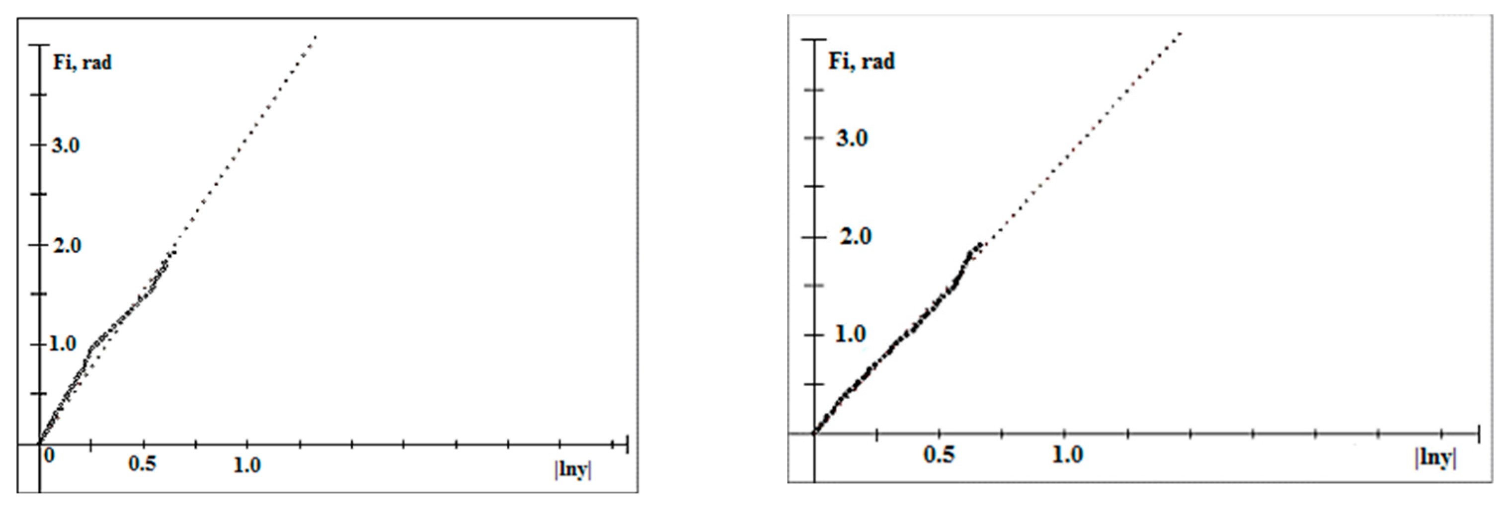
Normalized to 1 the normal distribution with the same standard deviation and with the same average value is shown (green dotted) in the histogram for comparison. Portions of the trailing and leading edges of the band, approximated by a logarithmic spiral, are shown as solid curves along with the original marking points on the right panel (see Section 3.2 for details). An example of logarithmic approximation of edges is shown in Figure 4.
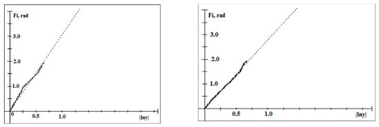
Figure 4.
Logarithmic approximation of the leading (left panel) and trailing (right panel) edges of the spiral band of TC Alma. The ordinate and abscissa of a semi-logarithmic coordinate system are the polar angle (Fi) and the absolute value of the logarithm of the relative polar radius (|lny|), respectively. The G-factors for the leading and trailing edges are 3.07 and 2.79, respectively.
In a number of cases, when the contour of the band is uneven and non-smooth, the HLS approximation was carried out within “logarithmic” boundaries.
2.4. Estimation of the Radius of Maximum Wind Speed
The radius of maximum wind speed (MWR) is not a critical parameter for the HLS approximation because Vm is proportional to where n < 1 (Equation (2)). Nevertheless, its value is needed for the HLS approximation. The criterion of closest proximity of the Vm histogram to a normal distribution was used to estimate “optimal” MWR. The choice of the normal distribution as a criterion for the adequacy of the calculated velocity histogram is due to the assumption regarding the features of the observed pattern of spiral bands as a cloud-rain mass lining up and concentrating along and, apparently, due to the prevailing wind streamline. The fact that the spiral bands have a limited width indicates the limited involvement of cloud mass in the area of the wind streamline, the influence of which decreases with distance from the wind streamline, probably due to a decrease in wind strength and, as a consequence, its speed. Therefore, it is logical to assume, as a first approximation, that the distribution of wind speeds in the spiral band is unimodal, the simplest model of which with the standard deviation parameter is the normalized normal distribution.
This MWR is obtained from several runs of the HLS approximation with different radii (at 5 or 10 km intervals), where the optimal estimate of MWR corresponds to the best similarity of the histogram to the normal distribution. After many experiments, it was found that, along with calculating skewness and kurtosis, the most plausible MWR estimate is obtained if the similarity is estimated using the so-called area factor (AreaFactor). This indicator shows the difference between the normalized area of the MWS histogram H(Vm) within plus/minus a standard deviation (from the mean value) and the same area of a normal distribution. Since, with a normal distribution, this area is 68% of the total area, the indicator is equal to
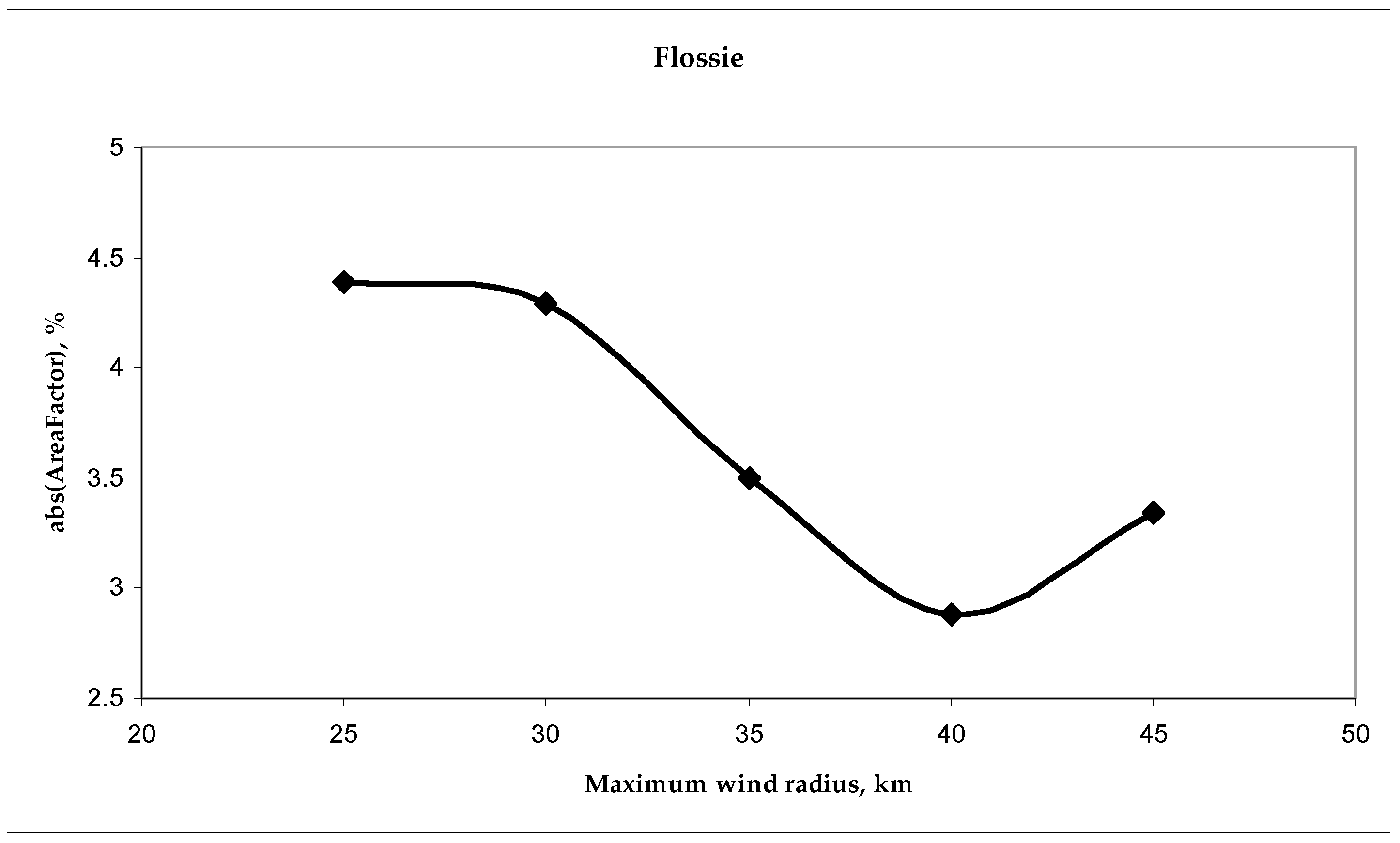
The denominator in (12) is the total area of the MWS histogram. To illustrate, Figure 5 shows a plot of successive AreaFactor estimates for TC Flossie, which has no visible eye.
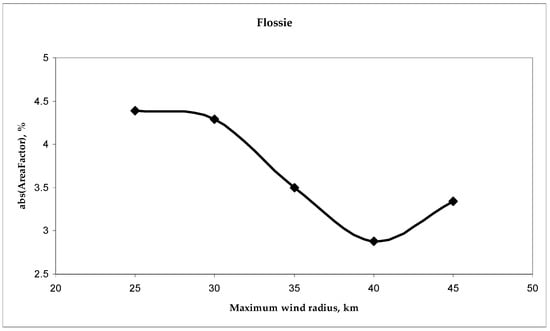
Figure 5.
AreaFactor estimates for different maximum wind radii of TC Flossie.
As follows from the graph, the minimum difference between the HLS Vm-histogram and the normal distribution in this case is achieved at MWR = 40 km.
It should also be noted that the MWR, as applied to SAR data, is not, strictly speaking, fully defined. This is because it is not known exactly what altitude this radius refers to, since the SAR data do not have altitude resolution. One can only speculate that the MWR determined in the HLS approximation probably refers to the spiral cloud-rain system that is the main contributor to the spiral SAR signature.
3. Results
3.1. Results of the HLS Approximation
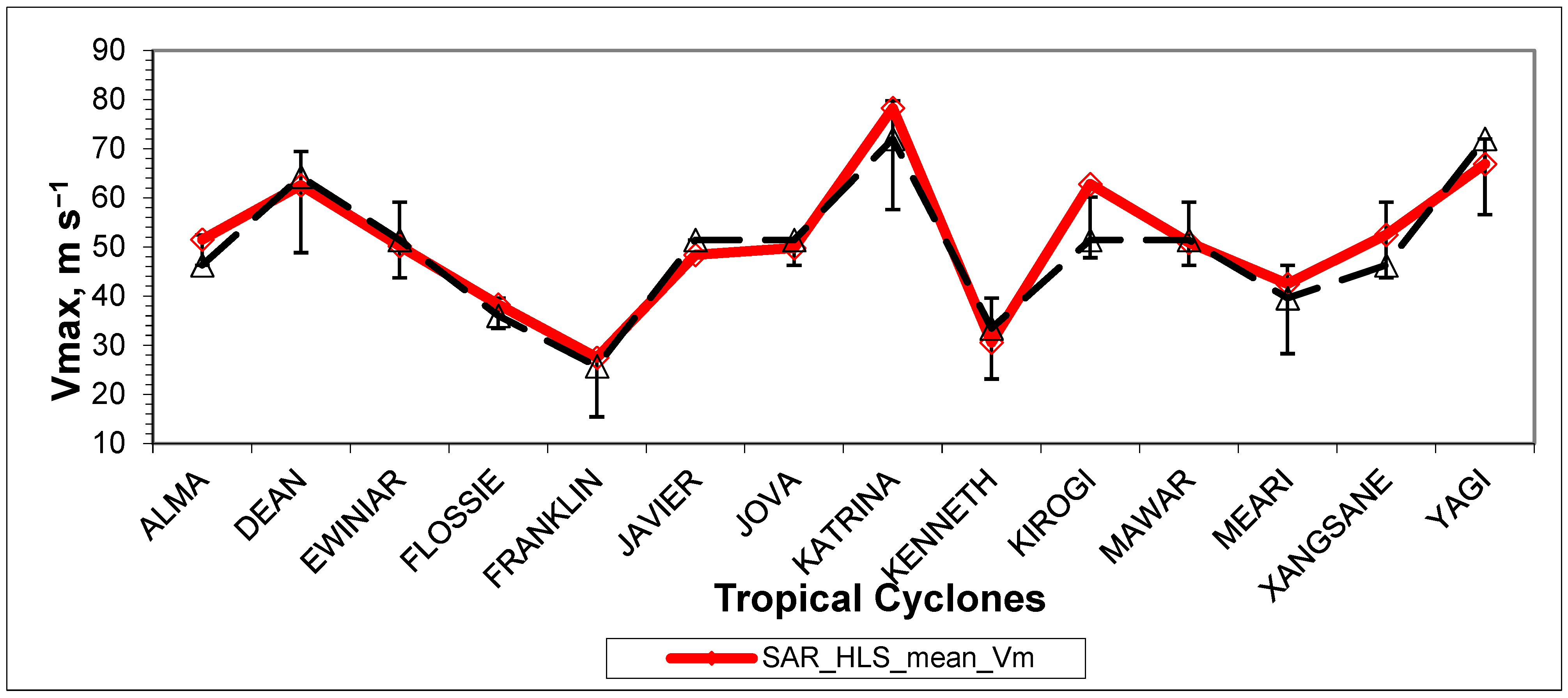
The results of the HLS approximation for all 14 considered TCs, similar to those presented in Figure 3 for TC Alma, and the logarithmic approximation of the edges of the spiral signatures (e.g., Figure 4), are presented in Supplementary Material along with the original best track data. The obtained estimates of MWS are presented in Table 2 and Figure 6, together with the best track data. Best track data were taken primarily from the corresponding graphs of “Best track maximum sustained surface speed curve” of Tropical Cyclone Reports from the National Hurricane Center and other sources, reflecting the scattering of speed measurements using different methods. The TCs are listed in alphabetical order in the tables and figures provided below.

Table 2.
Comparison of MWS derived from the HLS approximation with Best Track data.
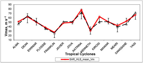
Figure 6.
Comparison of the mean MWS estimated from the HLS approximation of the spiral signatures of SAR images with the corresponding Best Track data. Error bars indicate the scattering of MWS measured by the different methods used to compile the Best Track profiles.
The root-mean-square-deviation (RMSD) calculated from all difference data and the same excluding the significant outliner data of TC Kirogi in column 7 of Table 2 (11.4 m s−1) were 4.04 and 2.9 m s−1, respectively. It should be noted that the MWS deviation for TC Kirogi was close to the upper limit of the scattering range of the Best Track data. Another reason for this deviation may be the significant contribution to the formation of SAR spiral signature by the cloud-rain field at the level of maximum wind (i.e., a higher altitude of 10 m above sea level, for which the Best Track data were compiled, e.g., https://library.wmo.int/records/68695-guide-to-instruments-and-methods-of-observation, accessed on 10 May 2024). To adjust the HLS data with the Best Track data, in this case, the HLS (SAR) Vm value must be reduced by approximately 20%, which corresponds to the 80% reduction factor used to match the aircraft data to the standard level (10 m) [31,32,33] (see also Best Track data for TC Dean at https://www.nhc.noaa.gov/data/tcr/AL042007_Dean.pdf, accessed on 10 May 2024 for an example).
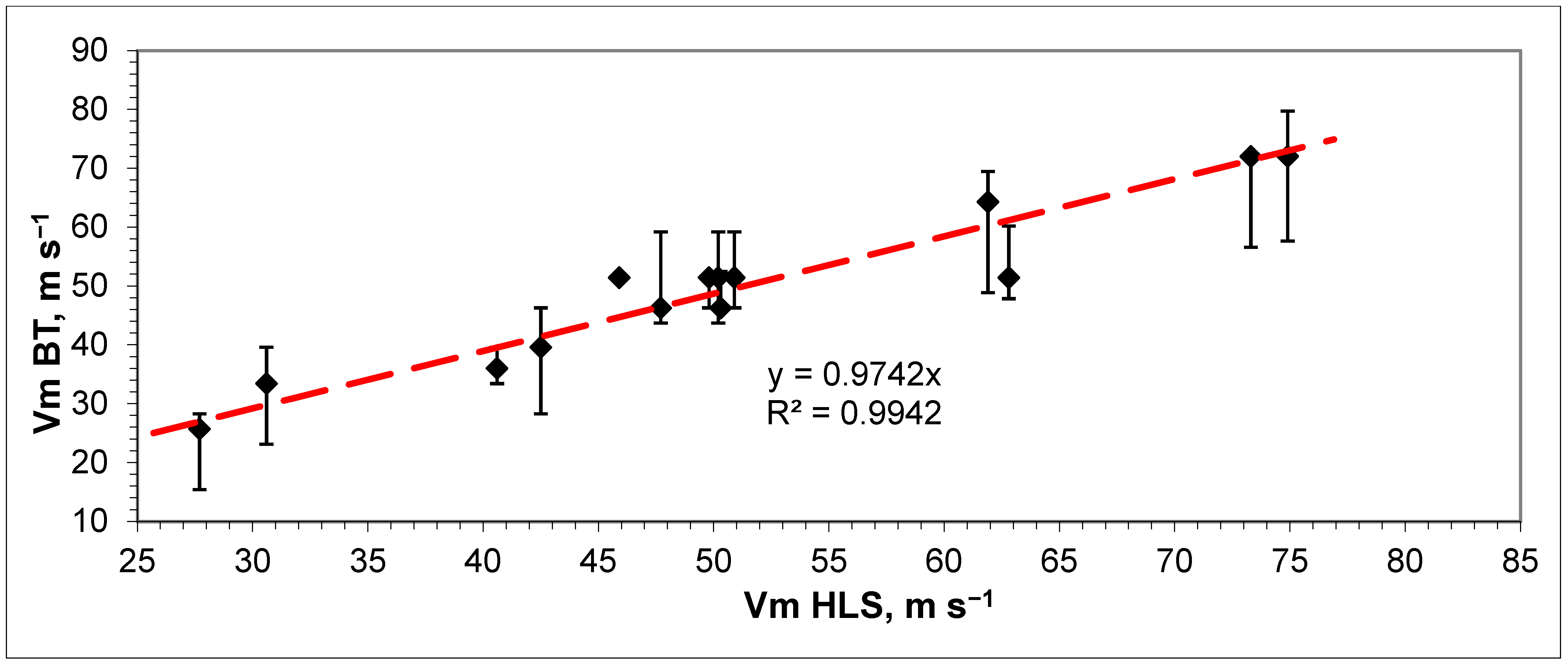
A scatter plot of these estimates with the calculated coefficient of determination (R2) is shown in Figure 7.
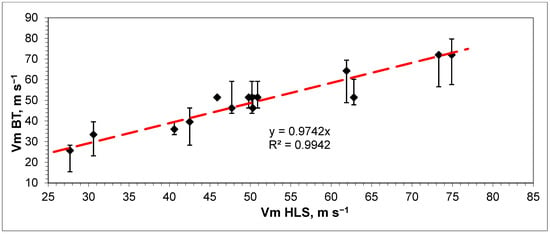
Figure 7.
Scatter plot of HLS estimates of mean MWS and Best Track data.
As shown in the graphs, the agreement between the HLS estimates and Best Track data can be considered satisfactory. The Pearson correlation coefficient between HLS estimates of mean MWS and Best Track data was about 0.95 (R2 ≈ 0.91). The significance values of R and R2 at the significance level of 0.05 and 12 degrees of freedom (df = n − 2) were confirmed (t-Student critical criteria for R (0.05, 12) = 2.18 < calculated t = 10.95 for R, and for R2 (0.05, 12) = 2.18< calculated t = 121). The confidence intervals for the correlation coefficient calculated through Fisher’s Z-transformation [34] were 0.85 ≤ R ≤ 0.985 (at the same significance level).
3.2. Logarithmic Approximation of the Edges of Spiral Signatures
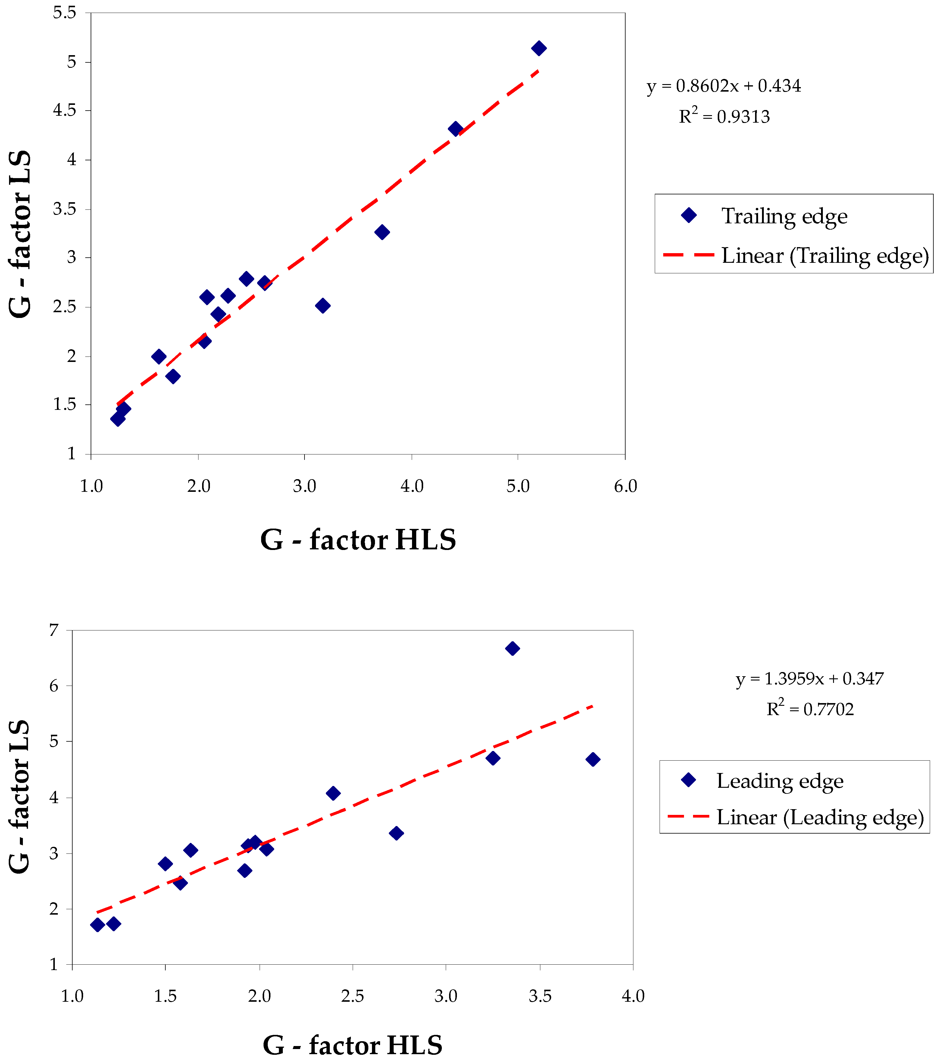
Logarithmic approximation of the trailing and leading edges of the signature was carried out using the least squares method within the lny-linear parts of the spiral bands (e.g., see Figure 4) and provided for all TCs in Supplementary Material. As a result, G-factors were determined for the corresponding edges. Comparison of the HLS-derived complex (11) of parameters B, ym, n, Vm and calculated Coriolis velocity (VC), with the measured G-factor for each edge, helped to increase the reliability of the HLS results. The determined values of the G-factor and the crossing angles from the logarithmic approach, along with the parameters determined from the HLS approximation, are presented in Table 3. Scatterplots of the G-factor_LS obtained in the logarithmic approximation, in comparison with the estimate GHLS (11) for both edges based on the data in Table 3 are shown in Figure 8. The error bars of estimation of G-factor (shown in Table 3, σ) and GHLS, which for most cases do not exceed 5%, are not shown in the graphs due to their insignificance. A satisfactory correlation was observed for both edges. The coefficient of determination R2 is approximately 0.93 (coefficient of correlation R ≈ 0.96) for the trailing edge and 0.77 (R ≈ 0.88) for the leading edge. This confirmed (validated) the results of the HLS approximation since only consistent values of the parameters in (11) can give such significant correlations. On the other hand, as calculations show, the GHLS did not correlate separately with MWS and with each other parameter in (11) due to reasons noted earlier in Section 2.2.2. This is illustrated by the following example. The range of calculated crossing angles of the trailing edge was from 11° (TC Kenneth, Vm = 30.6 m s−1) to 36° (TC Kirogi, Vm = 62.8 m s−1). Given these figures, it may seem surprising that a large crossing angle corresponds to a lower maximum wind speed and vice versa. This would seem to be completely contrary to the expected behavior of the crossing angle. Of course, this is not so since the given angles refer to different cyclones, for which not only the wind speed but also other parameters included in Formula (11) do not coincide.

Table 3.
Comparison of the G-factor and the crossing angle (α) obtained based on the least squares approximation of the logarithmic portion of the trailing and leading edges of the SAR spiral signatures (GLS) with its estimate based on the results of the HLS approximation of the entire spiral signature (GHLS, Equation (11)). Data from columns 7 to 11 are placed in two rows for each TC; the upper row relates to the trailing edge, and the lower row relates to the leading edge.
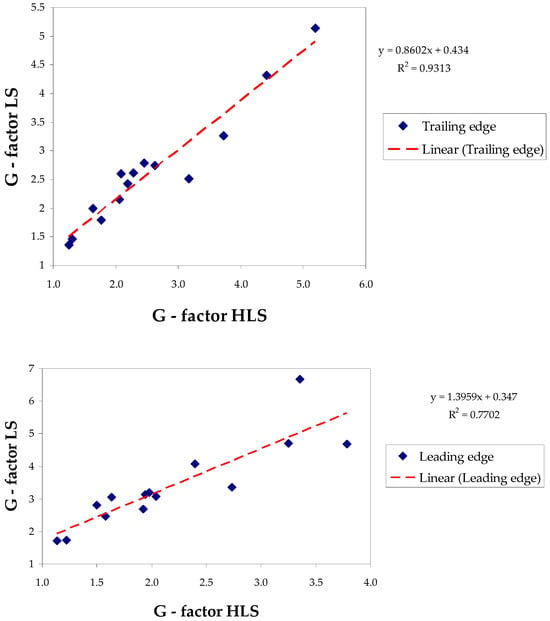
Figure 8.
G-factor (LS) scatterplots obtained in the logarithmic approach using the least squares method in comparison with the HLS estimate (GHLS, Equation (11)) based on the results of the HLS approximation for the trailing edge (top panel) and leading edge (bottom panel).
The significance of the Pearson correlation coefficient (R) and the coefficient of determination (R2) between G-factors at the 0.05 significance level was confirmed for both the trailing and leading edges. (t-Student critical criteria for R (0.05, 12) = 2.18 < calculated t = 12.53 for trailing edge and t = 6.34 for leading edge; the same for R2 were 159 and 40.2, respectively). Confidence intervals for the correlation coefficient calculated using Fisher’s Z-transformation [34] were 0.875 ≤ R ≤ 0.987 for the trailing edge and 0.66 ≤ R ≤ 0.96 for the leading edge (at the same significance level).
4. Discussion
The maximum wind speeds in TCs were estimated using the assimilation approximation from the spiral signatures of SAR images of 14 TCs in the Atlantic Ocean and western and eastern parts of the Pacific Ocean from 2002–2007. The spiral signatures were approximated by using the hyperbolic-logarithmic spiral (HLS), which has been previously used to approximate visible, infrared, and radar images of the TC cloud-rain field.
In addition to our previous studies on the topic of HLS, this work used data from logarithmic approximations of the trailing and leading edges of spiral signatures to improve the HLS approximation procedure and increase the reliability of its results. This serves as a self-validation method for HLS estimates. A physical model of changes in the crossing angle of the logarithmic portion of the edges of the spiral band is proposed and tested on SAR images of the TC. The predicted dependence of the crossing angle on the intensity of the cyclone is consistent with published observational data (assuming the remaining parameters included in (11) are constant). However, it is impossible to determine the intensity of a cyclone only by the crossing angle.
To increase the reliability of the assessment of the radius of the maximum wind speed, along with the standard skewness and kurtosis coefficients, the integral index (Area Factor) was used. This allows us to assess the closeness of the calculated histogram of maximum wind speed to the normalized normal distribution, which was chosen as a criterion for the adequacy of the calculated Vm-histogram.
The results of the MWS estimation using the HLS approximation show satisfactory agreement with the Best Track data for most of the cases considered. The root-mean-square deviation calculated from all difference data and the same excluding the significant outliner data were 4.04 and 2.9 m s−1, respectively. The range of measured maximum wind speeds in cyclones in this study using the HLS approximation method was 27–75 m s−1. Although there is no doubt that these estimates require further testing using more extensive statistical data, these results provide a promising basis for doing so. The collection of SAR data related to different cyclones and different acquisition times presented in this work demonstrated the potential to increase the statistical significance of the HLS method by continuing to accumulate similar data from existing and future remote sensing means. In addition to the methodological conclusion about the possibility of using the HLS approximation to estimate the intensity of TCs based on SAR data, this study indicated that the spiral signatures in SAR images are caused predominantly by the cloud–rain field of the TC. However, there was also a case where the signature was formed by a combination of arcing surface waves and showers. In general, observations near coastlines and islands are useful for studying the nature of SAR spiral signatures in more detail. In this study, MWS estimates based on SAR data were close to Best Track data in most cases. That is, the reflectivity of the spiral signatures changes mainly because of the second term in Equation (1). The advantage of the HLS method over other SAR methods mentioned in the Introduction is its ability to estimate TC intensity based only on SAR data without data from other sensors. SAR images of TCs contain two types of mutually complementary information caused by the wind field. The first type is sea surface reflectivity, which is shown in the literature to be driven by surface wind (σwind) and shows a correlation with surface wind speeds up to moderate speeds (~20–25 m s−1). The second type is the configuration of spiral SAR signatures, which was close to the configuration of the cloud-rain field of mature TCs, the parameters of which were also determined by the intensity of the cyclone. Thus, it appears that the combined processing of SAR images with an estimate of wind speed based on both sea surface reflectivity and the configuration of spiral signatures allows the tracking of TC intensity over the wide range of maximum speeds (categories). It also appears that deep learning methods have good potential to improve such a combination method, including recovering spiral signatures in regions with low-observable bands.
5. Conclusions
This study proposes a method based on the HLS approximation technique of TC spiral signatures in SAR images to determine the maximum sea surface wind speed. Despite some uncertainty about the main agents involved in the formation of spiral signatures, preliminary results showed satisfactory agreement with the Best Track data. To improve the reliability of the results, the logarithmic approximation of the part of spiral band edges was used. For the first time, a physical model of changing the crossing angle of the logarithmic portion of the edges was proposed and tested on SAR images of the TCs.
Compared with existing backscatter methods, the proposed method is not distorted by rain, which instead favors the detection of the spiral band. The results show that the HLS method can measure a wide range of maximum wind speeds. This is especially important for mature cyclones where continuous and accurate wind information is needed.
Overall, the application of HLS processing of SAR information from existing and future satellites promises to be an important source of TC data for a better understanding of the physics of this phenomenon, as well as for better forecasting it.
Supplementary Materials
The following supporting information can be downloaded at: https://www.mdpi.com/article/10.3390/rs16101750/s1.
Funding
This research received no external funding.
Data Availability Statement
No new data were created or analyzed in this study. Data sharing is not applicable to this article.
Acknowledgments
The author is pleased to express his gratitude to three anonymous reviewers of the manuscript for their valuable and helpful comments.
Conflicts of Interest
The author declares no conflict of interest.
References
- Williams, R.G.; Follows, M.J. Ocean Dynamics and the Carbon Cycle: Principles and Mechanisms; University Press: Cambridge, UK, 2011. [Google Scholar]
- Hasselmann, K.; Raney, R.K.; Plant, W.J.; Alpers, W.; Shuchman, R.A.; Lyzenga, D.A.; Rufenach, C.L.; Tucker, M.J. Theory of Synthetic Aperture Radar ocean imaging: A MARSEN view. J. Geophys. Res. 1985, 90, 4659–4686. [Google Scholar] [CrossRef]
- Ulaby, F.T.; Moore, R.K.; Fung, A.K. Microwave Remote Sensing: Active and Passive; Artech House: Reading, MA, USA, 1982; Volume II. [Google Scholar]
- Zhou, X.; Yang, X.F.; Li, Z.W.; Yu, Y.; Bi, H.B.; Ma, S.; Li, X.F. Estimation of Tropical Cyclone Parameters and Wind Fields from SAR Images. Sci. China Earth Sci. 2013, 56, 1977–1987. [Google Scholar] [CrossRef]
- Li, X.; Zhang, J.A.; Yang, X.; Pichel, W.G.; DeMaria, M.; Long, D.; Li, Z. Tropical Cyclone Morphology from Spaceborne Synthetic Aperture Radar. Bull. Am. Meteorol. Soc. 2013, 94, 215–230. [Google Scholar] [CrossRef]
- Monaldo, F.M.; Li, X.; Pichel, W.G.; Jackson, C.R. Ocean Wind Speed Climatology from Spaceborne SAR Imagery. Bull. Am. Meteorol. Soc. 2014, 95, 565–569. [Google Scholar] [CrossRef]
- Yang, X.; Li, X.; Pichel, W.G.; Li, Z. Comparison of Ocean Surface Winds from ENVISAT ASAR, MetOp ASCAT Scatterometer, Buoy Measurements, and NOGAPS Model. IEEE Trans. Geosci. Remote Sens. 2011, 49, 4743–4750. [Google Scholar] [CrossRef]
- Zhang, B.; Perrie, W. Cross-Polarized Synthetic Aperture Radar. A New Potential Measurement Technique for Hurricanes. Bull. Am. Meteorol. Soc. 2012, 93, 531–541. [Google Scholar] [CrossRef]
- Mouche, A.; Chapron, B.; Zhang, B.; Husson, R. Combined Co- and Cross-Polarized SAR Measurements under Extreme Wind Conditions. IEEE Trans. Geosci. Remote Sens. 2017, 55, 6746–6755. [Google Scholar] [CrossRef]
- Mouche, A.; Chapron, B.; Knaff, J.; Zhao, Y.; Zhang, B.; Combot, C. Copolarized and Cross-Polarized SAR Measurements for High-Resolution Description of Major Hurricane Wind Structures: Application to Irma Category 5 Hurricane. J. Geophys. Res. Ocean. 2013, 124, 3905–3922. [Google Scholar] [CrossRef]
- Combot, C.; Mouche, A.; Knaff, J.; Zhao, Y.; Zhao, Y.; Vinour, L.; Quilfen, Y.; Chapron, B. Extensive High-Resolution Synthetic Aperture Radar (SAR) Data Analysis of Tropical Cyclones: Comparison with SFMR Flights and Best Track. Mon. Weather. Rev. 2020, 148, 4545–4563. [Google Scholar] [CrossRef]
- Zhang, G.; Perrie, W.; Yang, J.; He, Y. Monitoring of tropical cyclone structures in ten years of radarsat-2 SAR images. Remote Sens. Environ. 2020, 236, 111449. [Google Scholar] [CrossRef]
- Yu, P.; Xu, W.; Zhong, X.; Johannessen, J.A.; Yan, X.-H.; Geng, X.; He, Y.; Lu, W. A Neural Network Method for Retrieving Sea Surface Wind Speed for C-Band SAR. Remote Sens. 2022, 14, 2269. [Google Scholar] [CrossRef]
- Han, X.; Li, X.; Yang, J.; Wang, J.; Zheng, G.; Ren, L.; Chen, P.; Fang, H.; Xiao, Q. Dual-Level Contextual Attention Generative Adversarial Network for Reconstructing SAR Wind Speeds in Tropical Cyclones. Remote Sens. 2023, 15, 2454. [Google Scholar] [CrossRef]
- Willoughby, H.E. The Dynamics of the Tropical Cyclone Core. Aust. Meteorol. Mag. 1988, 36, 183–191. [Google Scholar]
- Houze, R.A., Jr. Clouds in Tropical Cyclones. Review. Mon. Weather. Rev. 2010, 138, 293–344. [Google Scholar] [CrossRef]
- Yurchak, B.S. Description of cloud-rain bands in a tropical cyclone by a hyperbolic-logarithmic spiral. Russ. Meteorol. Hydrol. 2007, 32, 8–18. [Google Scholar] [CrossRef]
- Yurchak, B.S. The use of a spiral band model to estimate tropical cyclone intensity. In Current Topics in Tropical Cyclone Research; IntechOpen: London, UK, 2019; pp. 1–19. Available online: https://intechopen.com/chapters/68590 (accessed on 14 June 2019). [CrossRef]
- Yurchak, B.S. Estimation of tropical cyclone intensity from the satellite infrared images of its spiral cloud bands. Russ. Meteorol. Hydrol. 2018, 43, 581–590. [Google Scholar] [CrossRef]
- Yurchak, B.S. An estimate of the hurricane’s intensity from radar data using hyperbolic-logarithmic approximation. Int. J. Remote Sens. 2019, 40, 9629–9641. [Google Scholar] [CrossRef]
- Dvorak, V.F. Tropical cyclone intensity analysis and forecasting from satellite imagery. Mon. Weather. Rev. 1975, 103, 420–430. [Google Scholar] [CrossRef]
- Olander, T.L.; Velden, C.S. The advanced Dvorak technique: Continued development of objective scheme to estimate tropical cyclone intensity using geostationary infrared satellite imagery. Weather. Forecast. 2007, 22, 287–298. [Google Scholar] [CrossRef]
- Senn, H.V.; Hiser, H.W.; Low, E.F. Studies of hurricane spiral bands as observed on radar. Final Rep. U.S. Wea. Bur. Contract 1956, 49, Cwb-8735. [Google Scholar]
- Senn, H.V.; Hiser, H.W.; Bourret, R.C. Studies of Hurricane Spiral Bands as Observed on Radar; National Hurricane Research Project Report No. 12; U.S. Weather Bureau: Washington, DC, USA, 1957; 13p. [Google Scholar]
- Senn, H.V.; Hiser, H.W. On the origin of hurricane spiral rain bands. J. Meteorol. 1959, 16, 419–426. [Google Scholar] [CrossRef][Green Version]
- Fernandez, W. Organization and motion of the spiral rainbands in hurricanes. A review. Cienc. Y Technol. 1982, 6, 49–98. [Google Scholar]
- Anthes, R.A. Tropical cyclones. Their evolution, structure and effects. AMS Meteorol. Monogr. 1982, 19, 210. [Google Scholar]
- Lahiri, A. A study of cloud spirals of tropical cyclones. Mausam 1981, 32, 155–158. [Google Scholar] [CrossRef]
- Wong, K.Y.; Yip, C.L.; Li, P.W. A novel algorithm for automatic tropical cyclone fix using Doppler radar data. Meterol. Appl. 2007, 14, 49–59. [Google Scholar] [CrossRef]
- Lajoie, F.; Walsh, K. A diagnostic study of the intensity of three tropical cyclones in the Australian region. Part II: An analytic method for determining the time variation of the intensity of a tropical cyclone. Mon. Wea. Rev. 2010, 138, 22–41. [Google Scholar] [CrossRef]
- Powell, M.D.; Uhlhorn, E.W.; Kepert, J.D. Estimating maximum surface winds from hurricane reconnaissance measurements. Weather Forecast. 2009, 24, 868–883. [Google Scholar] [CrossRef]
- Franklin, J.L. Comments on “Estimating maximum surface winds from hurricane reconnaissance measurements”. Weather Forecast. 2011, 26, 774–776. [Google Scholar] [CrossRef]
- Powell, M.D.; Uhlhorn, E.W.; Kepert, J.D. Reply. Weather Forecast. 2011, 26, 777–779. [Google Scholar] [CrossRef]
- Devore, J.L. Probability and Statistics for Engineering and the Science, 6th ed.; Thomson Learning, Inc.: Toronto, ON, USA, 2004. [Google Scholar]
Disclaimer/Publisher’s Note: The statements, opinions and data contained in all publications are solely those of the individual author(s) and contributor(s) and not of MDPI and/or the editor(s). MDPI and/or the editor(s) disclaim responsibility for any injury to people or property resulting from any ideas, methods, instructions or products referred to in the content. |
© 2024 by the author. Licensee MDPI, Basel, Switzerland. This article is an open access article distributed under the terms and conditions of the Creative Commons Attribution (CC BY) license (https://creativecommons.org/licenses/by/4.0/).

