Article

An Embedded-GPU-Based Scheme for Real-Time Imaging Processing of Unmanned Aerial Vehicle Borne Video Synthetic Aperture Radar

1
School of Aerospace Science and Technology, Xidian University, Xi’an 710126, China
2
Guangzhou Institute of Technology, Xidian University, Xi’an 710126, China
3
School of Electronics and Information, Northwestern Polytechnical University, Xi’an 710129, China
*
Author to whom correspondence should be addressed.
Remote Sens. 2024, 16(1), 191; https://doi.org/10.3390/rs16010191
Submission received: 1 December 2023 / Revised: 29 December 2023 / Accepted: 1 January 2024 / Published: 2 January 2024
(This article belongs to the Special Issue Radar and Microwave Sensor Systems: Technology and Applications)

Abstract

:
The UAV-borne video SAR (ViSAR) imaging system requires miniaturization, low power consumption, high frame rates, and high-resolution real-time imaging. In order to satisfy the requirements of real-time imaging processing for the UAV-borne ViSAR under limited memory and parallel computing resources, this paper proposes a method of embedded GPU-based real-time imaging processing for the UAV-borne ViSAR. Based on a parallel programming model of the compute unified device architecture (CUDA), this paper designed a parallel computing method for range-Doppler (RD) and map drift (MD) algorithms. By utilizing the advantages of the embedded GPU characterized with parallel computing, we improved the processing speed of real-time ViSAR imaging. This paper also adopted a unified memory management method, which greatly reduces data replication and communication latency between the CPU and the GPU. The data processing of 2048 × 2048 points took only 1.215 s on the Jetson AGX Orin platform to form a nine-consecutive-frame image with a resolution of 0.15 m, with each frame taking only 0.135 s, enabling real-time imaging at a high frame rate of 5 Hz. In actual testing, continuous mapping can be achieved without losing the scenes, intuitively obtaining the dynamic observation effects of the area. The processing results of the measured data have verified the reliability and effectiveness of the proposed scheme, satisfying the processing requirements for real-time ViSAR imaging.

1. Introduction

The conventional synthetic aperture radar (SAR) is capable of performing ground detection, which possesses the advantages such as full-time, all-weather, and long-range imaging. Unfortunately, the SAR has certain limitations in detecting moving targets [1,2,3,4,5]. Compared to the conventional SAR, the video SAR (ViSAR) can perform high-frame-rate imaging and monitoring of the target area, obtaining dynamic observation effects of the area [6,7,8,9,10]. The unmanned aerial vehicle (UAV)-borne ViSAR has great application potential [11,12,13]. This technology integrates the advantages of unmanned flight platforms and the ViSAR while enabling high-precision high-frame-rate imaging of the target area, which not only reflects dynamic changes directly in the scene area, but also provides high-resolution images for resource exploration, terrain exploration, and disaster prediction and evaluation, etc. The UAV-borne ViSAR system receives a large amount of raw data, and the system processor has harsh power consumption limitations. This poses severe requirements for its imaging algorithm flow and the selection of appropriate processing platforms. Currently, the most commonly used imaging processing platforms include the digital signal processor (DSP), the field programmable gate array (FPGA), and the graphic processing unit (GPU). Yang et al. used a back projection (BP) algorithm to achieve real-time imaging processing of the SAR on a DSP hardware processing platform [14]. However, since the DSP adopts a serial processing method, which is not suitable for high-frame-rate real-time imaging of the ViSAR. In addition, due to its limited computing resources and low operating frequency, the DSP processing system is unable to realize high-speed parallel computing, not to mention satisfying the real-time imaging processing of large pixel numbers and high frame rates.
The FPGA-based processing system is the most widely used real-time signal processing platform, which not only performs parallel computing with small power consumption, but also achieves high data throughput [15,16]. In 2022, Cao et al. proposed an efficient architecture of an FPGA-based BP algorithm, which accomplished real-time SAR imaging processing on a single chip [17]. The above experiment adopted the Xilinx XC7VX690T FPGA platform, which took only 1.1 s for processing an image of 900 × 900 points at a 200 MHz clock frequency with a maximum resource utilization rate of over 80% and a system power consumption of 21.073 W. Although the FPGA has been widely used within the scope of SAR real-time imaging processing owing to its advantages such as excellent processing performance, low power consumption, high integration, and small physical dimensions, the development of FPGA still remains challenging along with its time-consuming development and validation cycle [18].
Despite the fact that the performance of the desktop-level GPU can satisfy the requirements of processing the ViSAR [19], their physical dimensions and power consumption are not suitable for the field of real-time imaging processing in which the payload is limited [20,21,22]. As high-performance computing technology develops, the computation power of the embedded platform has improved significantly. Compared with the desktop-level GPU, the embedded GPU not only has advantages of high integration, small size, low power consumption, low cost, and a short development cycle, but also solves the communication problem between the CPU and the GPU, satisfying the requirements of high-performance, low-power, and miniaturization for UAV-borne ViSAR imaging systems [23,24,25,26,27]. Implementing ViSAR imaging algorithms on the embedded GPU requires optimizing not only the entire imaging algorithm flow, but also the performances of memory and parallel computing throughout the calculation process, thereby satisfying the imaging processing requirements of the high frame rate and the high resolution for the ViSAR [28,29,30]. In 2022, Tian et al. reported a real-time airborne SAR imaging method based on an embedded GPU. They installed the Jetson TX2 on a UAV and processed the raw echo data captured by the UAV in real time. On a single-core and single-thread Jetson TX2 CPU, accomplishing a complete imaging algorithm took approximately 2640 s. However, accomplishing the same algorithm took only 193 s on the GPU, by adopting which the real-time performance and practicality of the SAR system can be significantly improved [31]. Subsequently, Yang et al. conducted the experimental tests using a chirp scaling (CS) algorithm for the image processing system on NVIDIA Jetson Nano, NVIDIA AGX Orin, and NVIDIA GeForce RTX 2060 Max-Q platforms. The test results of processing 8192 × 8192-point data on the above different platforms required 5.86 s, 0.395 s, and 0.956 s with the power consumptions of 5 W, 60 W, and 230 W, respectively [32]. The test results suggested that the embedded GPU platform exhibits better real-time performance while ensuring that imaging errors are within an acceptable range.
In this paper, we propose a real-time imaging processing method for the UAV-borne ViSAR based on an embedded GPU. The proposed method implements the signal generation and acquisition on an FPGA and accelerates the parallel computing real-time imaging processing on an embedded GPU after digital down conversion. Based on the CUDA parallel programming model, a parallel computing method for RD and MD algorithms is designed. By utilizing the advantages of the embedded GPU of high memory throughput and parallel computing, the efficiency of real-time ViSAR imaging has been effectively improved.
The key contributions of this paper can be summarized as follows.
(1)
In response to the problems of heavy computational duty and high computational complexity in traditional ViSAR algorithms, we proposed parallel computing methods for RD and MD algorithms based on the CUDA parallel programming model. By utilizing the advantages of the embedded GPU characterized with parallel computing, we improved the processing speed of real-time ViSAR imaging.
(2)
We adopted a unified memory management approach which can greatly reduce data replication and communication latency between the CPU and the GPU. In order to enhance memory access efficiency, it is essential to achieve the optimal use of both global and shared memory. When using FFT functions in the algorithm, configuring a cuFFT plan only once and releasing cuFFT resources uniformly after accomplishing all Fourier transforms can improve FFT execution efficiency and reduce memory overhead. Through the above operations, the efficiency of real-time ViSAR imaging has been further improved.
(3)
We proposed a high-frame-rate ViSAR real-time imaging processing system based on an embedded GPU, which has the characteristics of small size, low power consumption, and high-frame-rate real-time imaging. The robustness and effectiveness of the proposed system were verified by the measured data processing results on the Jetson AGX Orin platform, satisfying the requirements of ViSAR real-time imaging processing.
The remainder of this paper is summarized as follows. Section 2 introduces the imaging modes and algorithms of ViSAR, to which the motion compensation algorithms are formulated. Section 3 highlights the implementation and optimization steps of ViSAR imaging algorithms on an embedded GPU. Section 4 analyzes the experimental results of the test data. Section 5 discusses the importance of the integrated architecture through the task execution times of different platforms. Section 6 summarizes conclusions of this paper.

2. Imaging Algorithm of the ViSAR

Imaging Modes of the ViSAR

The azimuth pulses in the ViSAR are divided in a certain way and processed separately into SAR images. During the process of data collection and real-time imaging, overlapping may exist amongst scenes in each frame. Assume that under forward side-looking scenarios, the flight speed of the carrier aircraft is  v , the radar wavelength is  λ , the radar slant range is  R a , the antenna beamwidth is  β , and the synthetic aperture length is  L = N a / P R F v , where  P R F denotes the pulse repetition frequency, and  N a is the number of azimuth pulses. The imaging mode of the video SAR is shown in Figure 1.
The azimuth resolution of the above imaging system can be expressed as:
ρ a = λ 2 L / R a = P R F λ R a 2 N a v
when the imaging processing time required is less than the synthetic aperture time, and the frame rate of the imaging system is the reciprocal of the synthetic aperture time. According to Figure 1, when overlapping occurs in ViSAR imaging data, it is equivalent to re-segmenting each frame of the data, under which circumstance the frame rate of the system is no longer the reciprocal of the synthetic aperture time. Assuming that the number of azimuth pulse overlapping between each frame of the imaging data is  N 1 , the number of azimuth pulses updated each time is  N a N 1 . If the imaging processing time is much less than the time required to update  N a N 1 azimuth pulses, the real-time imaging frame rate  F of the system can be expressed as:
F = P R F ( N a N 1 ) .
The radar moves along a straight line at a speed of  v , and the distance from any point  P in the scene to the coordinate origin along the positive direction is  x n . During the radar beam’s continuous illuminating on point  P in the scene, let the slow time be  t m . Assuming that the signal transmitted by the radar is reflected back from the transmitting antenna to point  P in the scene, the base frequency signal  S 1 received by the radar can be expressed as:
S 1 = a r ( t ^ 2 R ( t m , R 1 ) c ) a a ( t m )   × exp ( j π γ ( t ^ 2 R ( t m , R 1 ) c ) 2 ) exp ( j 2 π f c ( t 2 R ( t m , R 1 ) c ) ) .
In the above Equation (3),  c denotes the speed of light,  t m denotes the slow time,  t ^ denotes the fast time,  t denotes the total time,  a r ( ) denotes the range window function of the radar signal,  a a ( ) denotes the azimuth window function of the radar signal,  γ denotes the frequency rate, and  R ( t m , R 1 ) denotes the instantaneous slant range that is expressed as:
R ( t m , R 1 ) = ( R 1 cos θ ) 2 + ( R 1 sin θ + x n v t m ) 2 .
Since the transmitted signal is characterized with high carrier frequency, the radar system performs differential frequency processing on the echo signal to sample it at a lower sampling rate in order to alleviate the processing pressure for signal receiving signal systems. Furthermore, because the different processing causes echoes from different distances to be not time-aligned, it is necessary to conduct deramping with respect to the output results of the intermediate frequency to align these echoes in time. The two-dimensional (2D) time-domain signal  S 2 after deramping is described as:
S 2 = r e c t ( t ^ T p ) a a ( t m ) exp ( j 4 π γ R 3 c t ^ ) exp ( j 4 π f c c R 3 ) ,
where  f c is the carrier frequency of the signal,  r e c t ( ) is the rectangular window function,  T p is the pulse width of the signal,  R 2 is the instantaneous slope distance when the radar’s central beam passes across the central point of the scene, and  R 3 = R ( t m , R 1 ) R 2 . Let the new range frequency variable be  f ^ r = γ t ^ , and the equivalent range frequency-domain azimuth time-domain signal  S 3 is obtained, which can be expressed by:
S 3 = r e c t ( f ^ r γ T p ) a a ( t m ) exp ( j 4 π ( R ( t m , R 1 ) R 2 ) c ( f ^ r + f c ) ) .
A range cell walk correction function  H 1 is constructed, which is written as:
H 1 = exp ( j 4 π v t m sin θ c ( f ^ r + f c ) ) ,
Function  H 1 is multiplied with the signal  S 3 to obtain the corrected signal  S 4 , which is written as:
S 4 = r e c t ( f ^ r γ T p ) a a ( t m ) exp ( j 4 π ( R ( t m , R 1 ) R 2 + v t m sin θ ) c ( f ^ r + f c ) ) .
A quadratic range pulse compression and range cell migration correction function  H 2 is constructed, which is written as:
H 2 = exp ( j π 2 λ R 2 β 2 c 2 ( 1 β 2 ) 3 f ^ r 2 ) exp ( 2 π R 2 c β 2 f r ) ,
Function  H 2 is multiplied with 2D frequency-domain signal  S 4 , and then quadratic range pulse compression and range migration correction is performed on the  S 4 . Subsequently, an inverse fast Fourier transform (IFFT) is performed with respect to the above  S 4 that is pulse-compressed and corrected, after which the range-Doppler-domain signal  S 5 is thus obtained, which can be expressed as:
S 5 s i n c ( B ( t ^ r 2 ( R 1 R 2 + x n sin θ ) c ) ) a a ( f a ) exp ( j 4 π x n sin θ c f c ) × exp ( j 2 π v cos θ R 1 f a m 2 f a 2 ) exp ( j 2 π f a x n v ) exp ( j Φ E ) .
The above operations realize range migration correction for the signal. It is known that the term of theoretical azimuth pulse compression exists in the azimuth phase. However, the phase error  Φ E is mixed into the azimuth phase, which causes defocusing in the final azimuth-focused image. In addition, the velocity variation of the airborne platform equipped with the radar during flight also affects the final azimuth resolution, resulting in the geometric deformation of the final focused image. In order to eliminate the above geometric deformation of the image caused by the velocity variation of the radar platform, we construct the azimuth scaling function  H 3 , which is written as:
H 3 = exp ( j 2 π v cos θ R 1 f a m 2 f a 2 ) exp ( j π k 1 f a 2 ) ,
In the above Equation (11),  k 1 is the scaling factor and  k 1 = 2 v 2 / λ R 4 , where  R 4 is the scaling slant range. Then, the azimuth scaling function  H 3 is multiplied with the range-Doppler-domain signal  S 5 to realize geometric micro correction of the image, thereby obtaining the azimuth-scaling processed signal. An azimuth IFFT is performed with respect to the above signal, we obtain the 2D time-domain signal  S 6 , which is written as:
S 6 s i n c ( B ( t ^ r 2 ( R 1 R 2 + x n sin θ ) c ) ) a a ( t m )   × exp ( j 4 π x n sin θ c f c ) exp ( j π k 1 ( t m x n v ) 2 + j φ e ) ,
where  φ e denotes the time-domain form of the phase error  Φ E .
The 2D time-domain signal is divided into azimuth-overlapped sub-apertures, and a map drift (MD) method is conducted for estimating phase errors of each individual sub-aperture. Then, sub-aperture phase errors are concatenated to obtain the phase error. Phase error compensation is performed with respect to the phase error estimated by the sub-aperture MD method to eliminate errors in the signal, and subsequent precise focusing is realized, thereby obtaining 2D time-domain signal  S 7 that is phase-error-compensated, which is written as:
S 7 s i n c ( B ( t ^ r 2 ( R 1 R 2 + x n sin θ ) c ) ) a a ( t m )   × exp ( j 4 π x n sin θ c f c ) exp ( j π k 1 ( t m x n v ) 2 ) .
The azimuth dechirp function  H 4 is constructed, which is expressed as:
H 4 = exp ( j π k 1 t m 2 ) .
The azimuth dechirp function is multiplied with the phase-error-compensated 2D time-domain signal to realize Doppler-domain focusing, which is expressed as:
S 8 s i n c ( B ( t ^ r 2 ( R 1 R 2 + x n sin θ ) c ) ) a a ( t m ) exp ( j 2 π k 1 x n v t m ) × exp ( j 4 π x n sin θ c f c ) exp ( j π k 1 ( x n v ) 2 )
The processing flow of the high-frame-rate ViSAR real-time imaging algorithm is demonstrated in Figure 2.
However, in order to satisfy the demands of high-frame-rate and high-resolution real-time imaging, the raw data volume received by unmanned aerial vehicle (UAV) video synthetic aperture radar (SAR) systems continues to increase, imposing elevated requirements on real-time imaging processing platforms. While traditional CPUs exhibit strong single-core processing capabilities, they have been proven to be insufficient for handling such massive data volumes. Therefore, the proposed method implements the signal generation and acquisition on an FPGA and accelerates the parallel computing real-time imaging processing on an embedded GPU after digital down conversion. Specifically, by utilizing the CUDA parallel programming model, we devised parallel computation methods for RD and MD algorithms. A unified memory management approach is employed to eliminate data copying and communication latency between the CPU and the GPU. The embedded GPU’s high memory throughput and parallel computing capabilities are fully harnessed, significantly enhancing the efficiency of real-time video SAR imaging.

3. Implementing and Optimizing the Embedded-GPU-Based ViSAR

3.1. CUDA-Implemented RD Algorithm

Figure 3 shows the implementation process of the range-Doppler (RD) algorithm on an embedded GPU, with the specific steps are presented as follows.
Step 1. The original data are initially stored consecutively in the range direction in an embedded GPU. Firstly, perform a range fast Fourier transform on the data, and call cuFFT library function in the compute unified device architecture (CUDA) to conduct a one-dimensional (1D) range Fourier transform on the original data. Calling the cuFFT library function requires configuring a cuFFT plan. After accomplishing the fast Fourier transform (FFT) operations, the cuFFT plan must be freed. Since the configuring and freeing of the cuFFT plan require calling the cuFFT library function repeatedly throughout the entire execution process of the RD algorithm, it consumes a great amount of time. Given the above situation, configuring only the first call to the cuFFT library function and then freeing it after the last call can save lots of time.
Step 2. Set the first kernel function. Then, parallel compute the data on which a range-direction FFT is performed and the function on which range-direction deramping is conducted, and then multiply the two of them. Truncate the data processed by the range-direction deramping to reduce the number of computation points to minimize computational complexity, thereby improving computational efficiency. After the above operations, perform a range-direction FFT with respect to the truncated data.
Step 3. Set the second kernel function, and then parallel compute the multiplication of the data on which the range walk correction is conducted, the inertial navigation compensation factor, and the data on which the range-direction FFT is performed. Then, set the matrix transposing kernel function to transpose the output data of the second kernel function arranged consecutively in the range direction to the data arranged successively in the azimuth direction. The purpose of setting the transposed matrix is to ensure that the imaging data are consecutively read during the azimuth-direction processing, so the memory access in kernel functions can be merged to increase the memory access bandwidth while reducing access latency. Meanwhile, the matrix-transposing kernel functions utilize shared memory to optimize global memory access, improving the execution efficiency of kernel functions.
Step 4. Perform azimuth-direction FFT operations on the transposed data, set the third kernel function, and then parallel compute the multiplication of the quadratic-range pulse compression function, the range cell migration correction function, and the data on which an FFT is performed in the azimuth direction.
Step 5. Call the matrix-transposing kernel function to transpose the resultant data of the third kernel function, and then, transpose the data arranged consecutively in the azimuth direction to those arranged consecutively in the range direction.
Step 6. Perform an range-direction IFFT with respect to the transposed data. Set the fourth kernel function, and then parallel compute the multiplication of the azimuthal pulse compression function and the data on which an IFFT is performed, after which phase compensation is conducted. Subsequently, the matrix-transposing kernel function is called to transpose the original data that are stored in the range direction into those stored in the azimuth direction, and conduct an IFFT in the azimuth direction with respect to the transposed data, thereby accomplishing the imaging process of the RD algorithm.

3.2. CUDA-Implemented MD Algorithm

After the original data are processed by the RD algorithm, they enter into the flow of the MD algorithm, with the specific flow demonstrated in Figure 4.
Firstly, the preliminary imaging results are truncated to minimize computational complexity and improve computational efficiency without trading off accuracy. Then, estimate the motion error, and compensate for the motion error of the captured preliminary imaging results. Finally, after deramping in the azimuth direction, the final imaging results are obtained, with the flowchart of error estimation demonstrated in Figure 5.
The specific implementing steps of the MD algorithm on an embedded GPU are formulated as follows.
Step 1. Truncate preliminary imaging results. This helps minimizing computational complexity while improving computational efficiency without trading off accuracy. Then, estimate the motion error according to the original data, as shown in Figure 6.
Step 2. The truncated data are subjected to azimuth block processing, with the data being partially overlapped in the azimuthal direction. The divided minimum unit of the resultant block is an even power of two. Then, set the fifth kernel function to perform deramping in the azimuth direction on each block of data.
Step 3. Divide the deramped data into two secondary sub-blocks of the same size, and then perform an FFT in the azimuth direction on the two blocks after accomplishing zero padding in the azimuth direction.
Step 4. Take the frequency-domain amplitude in the azimuth direction of the two secondary sub-block data on which an FFT is performed, i.e., take absolute values of the data on which the FFT is conducted. Then, perform an FFT in the azimuth direction on the two secondary sub-block data after taking absolute values.
Step 5. Set the sixth kernel function, parallel compute the multiplication of the two secondary sub-block data on which an FFT is conducted in the azimuth direction, and then, perform an IFFT in the azimuth direction with respect to the multiplication result.
Step 6. Set the seventh kernel function, parallel compute the azimuth amplitude of the data on which an IFFT is performed, and then, perform the summation of the data in the range direction.
Step 7. Set the eighth kernel function, parallel compute the results of error fitting estimation. Repeat steps 3 to 7, until the motion errors of full aperture are obtained.
Step 8. Set the ninth kernel function and parallel compute the multiplication of the motion error and the preliminary imaging result to compensate the motion error.
Step 9. Set the tenth kernel function, and parallel compute the multiplication of the data for which the motion error is compensated and the deramping function in the azimuth direction, thereby obtaining the final imaging result.

3.3. Optimizing ViSAR Imaging

Due to the linear storage characteristics of the original SAR data and the processed intermediate result data in computer memory, we adopted the method of matrix transposition. This suggests that during data processing in the azimuth direction, the data are stored in the azimuth direction, while during that in the range direction, the data are stored in the range direction, thereby improving the efficiency of the processor in reading and writing data in memory.
Considering the characteristics of the embedded GPU platform, this paper adopted the following optimization approaches.
(1)
Unified memory management. It has been acknowledged that the GPU is not an independent computing platform; instead, it must collaborate with the CPU to form a heterogeneous computing architecture. As shown in Figure 6a, conventional heterogeneous computing architectures of a GPU and a CPU are generally discrete, where the GPU and the CPU have their own independent memory. They are connected through peripheral component interconnect express (PCIe), and data need to be transmitted through a PCIe bus. Conversely, the heterogeneous computing architecture of an embedded GPU is integrated, where a CPU and a GPU are integrated on a single chip and share main memory on physical addresses. As shown in Figure 6b, in the embedded GPU, the CPU and the GPU do not have independent memory, thus not requiring data transmission through a PCIe bus.
Figure 6. System architecture of a heterogeneous computer: (a) discrete architecture; (b) integrated architecture.
Remotesensing 16 00191 g006
The data transmission method used by the conventional discrete architecture of the “CPU plus GPU” heterogeneous platform is to reserve some memory space in the CPU and the GPU separately. Specifically, data are first read into the CPU and then copied from the CPU into the GPU for subsequent processing. After completing data processing, the data are then copied from the GPU to the CPU. Since data transmission is affected by the bandwidth of the PCIe bus, this physical bottleneck can hardly be overcome. In addition, when the amount of data is tremendous, transmitting data is quite time-consuming, which severely degrades the algorithm performance. For the embedded GPU, due to the fact that the CPU and the GPU share the same physical memory, adopting this method for transmitting data is rendered a meaningless copy in memory, seriously wasting the memory resources of the embedded GPU and greatly limiting the amount of data that the embedded GPU can process.
In response to the above problems, considering the integrated architecture of the embedded GPU, this paper adopts the unified memory method for memory management. This approach defines a managed memory space where allocated space can be accessed on both the CPU and the GPU using the same memory address (i.e., pointer). The unified memory provides a “unified data pointer” model, which is similar to zero-copy memory in concept. Regardless of adopting unified memory or zero-copy memory in the embedded GPU, neither will additional space in memory be occupied, nor will memory copy happen between the CPU and the GPU. While using zero-copy memory can save memory space and reduce data-copying time, it disables caching and may potentially cause a performance degradation. In contrast, adopting unified memory not only avoids redundant memory reservation and data transmission, but also prevents the performance degradation caused by disabling the cache, thereby effectively saving the memory space of the embedded GPU. In addition, adopting unified memory simplifies the program code and improves its maintainability.
(2)
Aligned and pinned memory access. Global memory is the largest and most commonly used memory in the GPU, and most of the GPU applications are limited to memory bandwidth. Therefore, maximizing the utilization of global memory bandwidth is the key to optimizing kernel function performance. Using aligned and pinned memory access to the largest extent can maximize the efficiency of memory access and achieve optimal performance when reading and writing data. The former refers to the fact that the first address of a memory transaction is an even multiple of the cache line size used for transaction services (32 bytes of L2 cache or 128 bytes of L1 cache). The latter refers to all threads in a thread warp accessing a contiguous block of threads. It can be observed from Figure 7 that the aligned and pinned memory access only requires one data transfer to complete data access.
Figure 7. Aligned and pinned memory access.
Remotesensing 16 00191 g007
Figure 8 demonstrates the schematic diagram of unaligned and unpinned memory access, in which multiple data transfers are required to complete data access. During this process, most of the bytes obtained are not used, thus wasting bandwidth and affecting the speed of accessing GPU memory. Therefore, accessing global memory must maximize the use of aligned and pinned memory access to effectively mitigate performance degradation caused by memory access.
(3)
Shared memory. Shared memory is one of the important types of memory space for the GPU, which also functions as a critical tool for optimizing CUDA programs. The two key attributes to measuring the optimization of memory performance is the delay and bandwidth. Compared to global memory, shared memory has a latency reduction of approximately 20 to 30 times and a bandwidth increase of approximately 10 times. Therefore, it can be used to prevent global memory latency and bandwidth from being degraded on memory performance. When each thread block starts execution, certain amounts of shared memory are allocated and the address space of this shared memory is shared by all threads in the thread block. Accessing shared memory can be categorized into the following three modes:
(a)
Parallel access: accessing multiple banks from multiple addresses.
(b)
Broadcast access: a single address reads a single bank.
(c)
Serial access: multiple addresses access the same bank.
In the parallel access mode, accessing shared memory can be as fast as registers. In the broadcast access mode, although the utilization of bandwidth is low, the accessing can also be as fast as registers. In the serial access mode, bank conflict will occur, if multiple addresses accessed belong to the same bank, under which circumstance requests have to be made in a serial manner. As a result, the time required to satisfy these accesses will greatly increase. Avoiding bank conflict must be ensured when using shared memory. Under certain scenarios where parallel and broadcast access are not possible, memory filling methods shall be adopted to avoid the conflict. As for both RD and MD algorithms, matrix transposition and array multiplication can effectively utilize shared memory in kernel functions, thereby optimizing memory access.
(4)
FFT operation. In RD and MD algorithms, multiple FFT/IFFT operations need to be executed to accomplish compression in the azimuth direction and the range direction. Based on CUDA implementation, the cuFFT library provides highly optimized Fourier transforms. Using the cuFFT library for FTs not only improves the computation speed, but also saves the development time of algorithms. The configuration of the cuFFT library is accomplished through an FFT plan, which defines a single transformation operation to be performed. When calling the cuFFT library, a plan is configured first. The cuFFT library uses the plan to obtain memory allocation, memory transfer, and kernel startup to execute transformation requests. After FT operations are completed, cuFFT resources need to be released.
Frequently configuring cuFFT plans is time-consuming. If the cuFFT plan is reconfigured and then released every time when it is used for FTs, the execution efficiency will decrease. Therefore, it is reasonable to configure a cuFFT plan for only one time and then uniformly release cuFFT resources after all FT operations are completed. Subsequently, pass the same address to the input and output parameters each time to conduct FFT operations, thereby improving the execution efficiency of FFTs while reducing memory overhead. Note that the data obtained from accomplishing IFFTs using the cuFFT library are not normalized. Therefore, to ensure the correctness of the obtained data, the data must be divided by the number of FT points after conducting IFFTs.
In summary, the optimization of video SAR imaging algorithms in this paper mainly includes the following points:
(1)
The unified memory approach is used for memory management. The advantage of this approach lies in the fact that allocated space can be accessed using the same memory address (i.e., pointers) on both the CPU and the GPU, thereby avoiding the need for occupying additional space in memory and performing data copying between the CPU and the GPU.
(2)
In order to maximize memory access efficiency, we should fully leverage the global memory bandwidth. When accessing memory, it is advisable to use aligned memory and pinned memory to achieve the optimal performance.
(3)
Shared memory is reasonably used. Shared memory, compared to global memory, exhibits lower latency (approximately 20–30 times lower) and higher bandwidth (approximately 10 times higher). Therefore, in range-doppler (RD) and multi-look processing (MD) algorithms, operations involving matrix transposition and array multiplication can be optimized using shared memory within the kernel function to enhance memory access.
(4)
When using FFT functions in the algorithm, configuring a cuFFT plan only once and releasing cuFFT resources uniformly after accomplishing all Fourier transforms can improve FFT execution efficiency and reduce memory overhead.

4. Experimental Results and Analysis

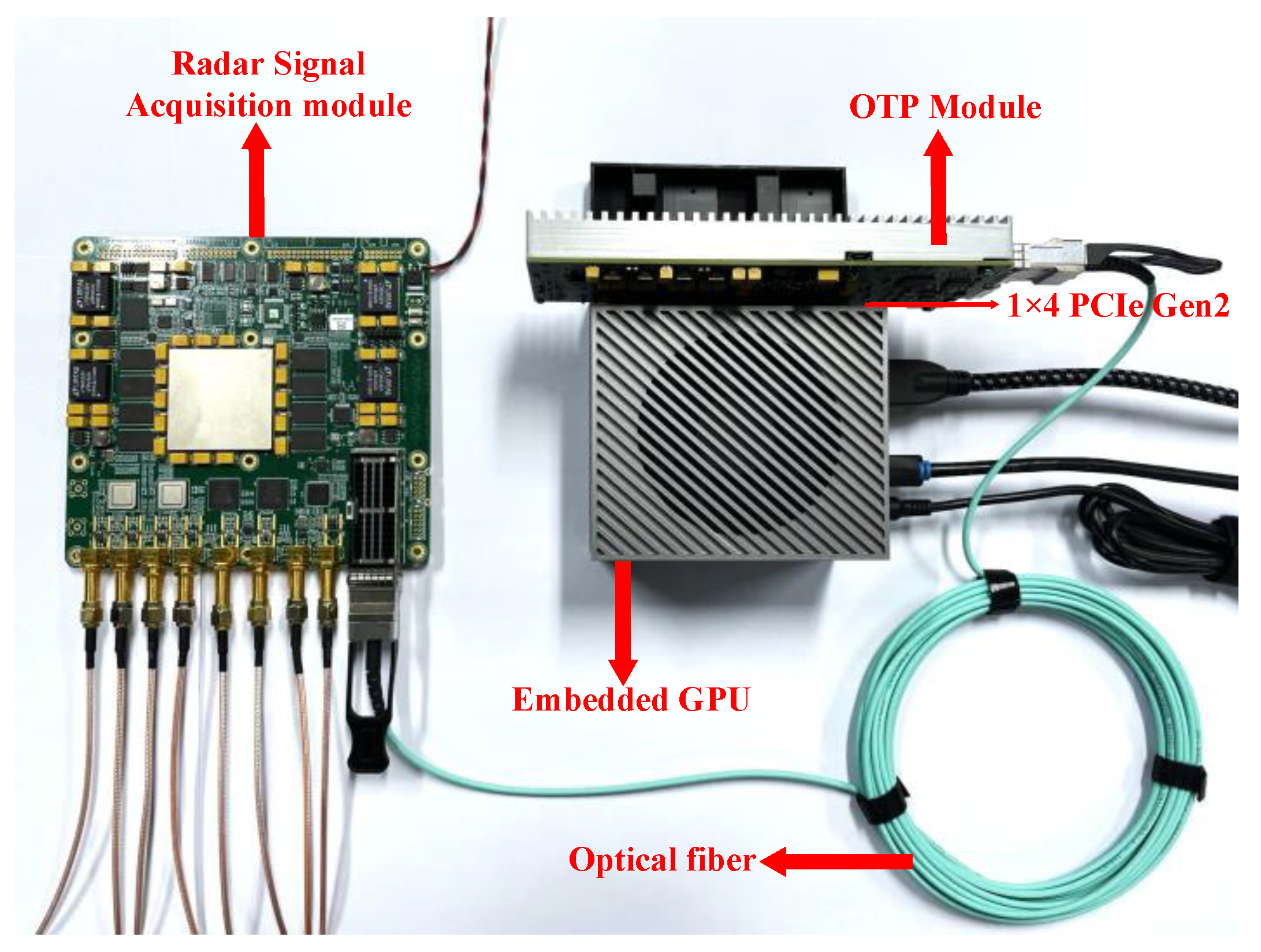
In order to verify the processing performance of ViSAR imaging of the embedded GPU, we conducted real-time ViSAR imaging processing on the embedded GPU using measured data. The platform used for the GPU was the Jetson AGX Orin. The architecture of the embedded GPU ViSAR high-frame-rate imaging system is shown in Figure 9.
The system included a radar signal acquisition module, an embedded GPU, and an optical fiber-to-PCIe (OTP) module. The radar signal acquisition module was responsible for signal generation and acquisition. After digital down conversion, the real-time imaging processing part that could be calculated in parallel was sent to a data-processing module. The data-processing module included the embedded GPU and the OTP module. The embedded GPU and the OTP module were interconnected via a PCIe bus. The data between the raw data delivery module and the OTP module were transmitted through an optical fiber.
A comprehensive analysis was performed, which took into account the atmospheric attenuation chart shown in Figure 10 and considered the variations in signal transmission strength under different conditions.
Based on the millimeter-wave radar’s capability to operate in all-weather and all-day conditions, unaffected by adverse weather conditions, and recognizing its advantages in precision, stability, sensitivity, and interference resistance, we selected the 94 GHz millimeter-wave radar band. We performed data collection in real-world environments to ensure the practical feasibility of our research. During the data processing phase, we exported radar data to the embedded GPU at an echo rate through a data recorder. The design of this process aimed to simulate real-time processing on board, allowing us to conduct effective performance evaluation under conditions that closely resembled practical application scenarios. The embedded GPU platform used in this paper was the Jetson AGX Orin. For comparative analysis, experiments were also conducted on the Jetson Nano, the Jetson TX2, and the RTX 2060 Max-Q platforms. Table 1 lists the hardware parameters for all experimental platforms.
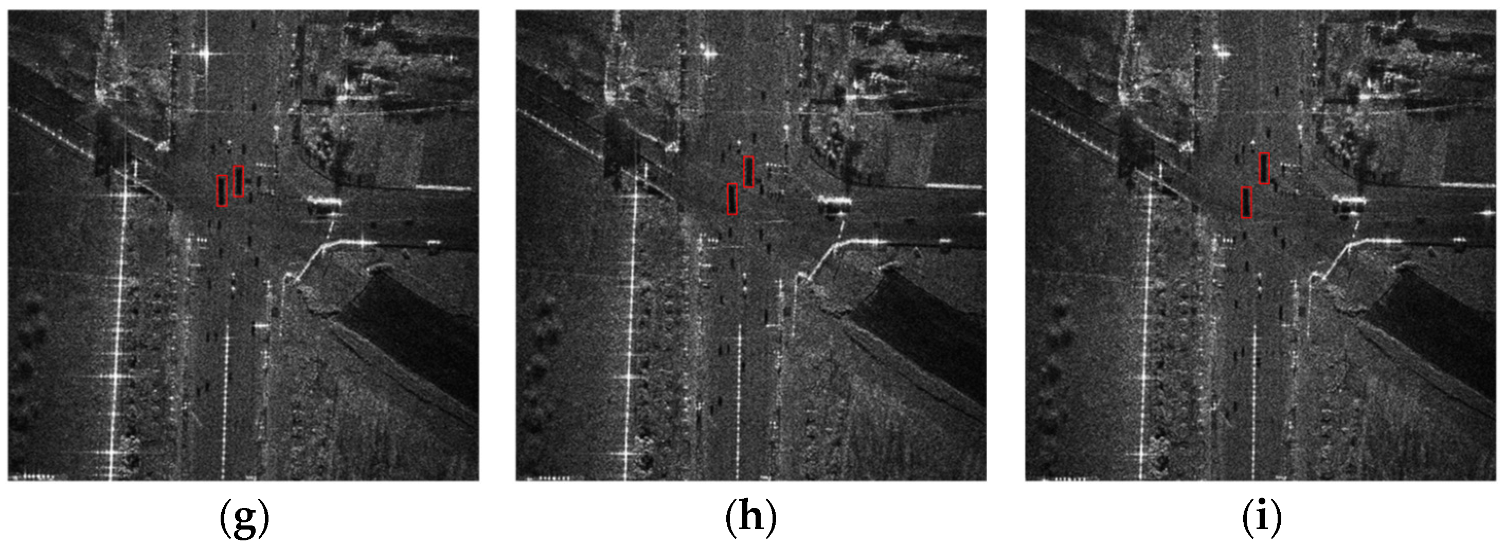
Figure 11 shows the nine-consecutive-frame imaging results of the ViSAR obtained by conducting the method of high-frame-rate ViSAR real-time imaging on the Jetson AGX Orin platform.
The area marked with a red box was a moving car. The original experimental data used were 2048 × 2048 single-precision floating-point complex data. The total processing time for the above data was 1215 ms, and the imaging time for each frame was 135 ms. The test results met the requirement for real-time imaging frame rates of 5 Hz. In practical tests, continuous imaging can be achieved without losing the scene, intuitively reflecting the positional changes of the car.
In order to verify the ViSAR imaging processing performance of the embedded GPU, we adopted the measured data for processing, using the original data of 2048 × 2048 single-precision floating-point complex data points. Based on the Jetson AGX Orin platform, we processed the data using the parallel designed RD and MD algorithms. On the MATLAB platform, we also processed the same data using the traditional RD and MD algorithms. We obtained a frame of ViSAR imaging results separately, which are presented in Figure 12.
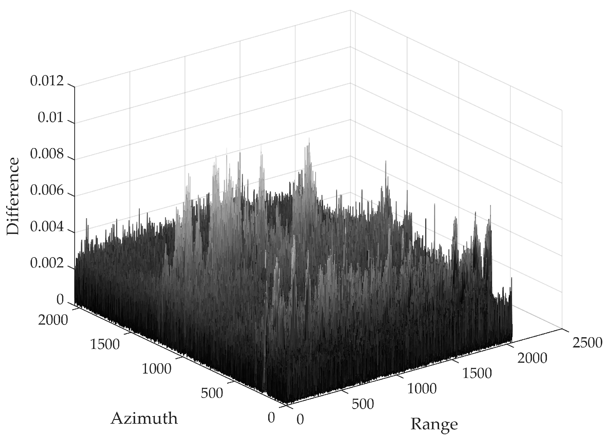
Figure 13 shows the errors between the imaging results obtained by using the embedded GPU and those by MATLAB.
Due to the large original echo values of the ViSAR, small differences are amplified in ViSAR imaging algorithms. The calculations in MATLAB are generally considered accurate enough. Therefore, the calculation results of MATLAB were used as a reference to calculate the difference of the Jetson AGX Orin processing result. We adopted the percentage to measure the difference (i.e., using the absolute difference divided by the result in MATLAB), and the maximum percentage difference did not exceed 0.8%, which is within an acceptable range. Therefore, the imaging accuracy of implementing the real-time ViSAR imaging processing algorithm on the embedded GPU can satisfy the requirements in practical applications.
Within the realm of image quality evaluation metrics, the PSNR is primarily employed to assess the degree of distortion between two images, while the SSIM is utilized to compare the structural similarity between two images. To investigate the variations in the quality of video SAR frame images during the algorithm optimization process, we conducted a comparative analysis using the PSNR and the SSIM to evaluate the quality of ViSAR frame images obtained through the proposed method in comparison to the those with the MATLAB method. The comparative results are presented in Table 2:
We evaluated the real-time performance of the ViSAR imaging processing process implemented on the Jetson AGX Orin platform, the Jetson NANO platform, the Jetson TX2 platform, and the RTX 2060 Max-Q platform and compared the results with those of the real-time performance of the ViSAR imaging processing process on the CPU platform without parallel computing. The CPU platform used was Intel Core i7-10875H, and the Jetson AGX Orin platform adopted the 60 W power consumption mode. The imaging processing time statistics are listed out in Table 3.
It can be seen from Table 3 that the processing time of the Jetson AGX Orin platform was the shortest, and its performance surpassed those of conventional higher power consumption computers equipped with GPU RTX 2060 Max-Q. Moreover, owing to the advantages such as the number of CUDA cores, GPU frequency, and memory, the processing time of the Jetson AGX Orin platform was much smaller than those of the Jetson Nano and the Jetson TX2. Compared to conventional CPUs, using an embedded GPU for parallel computing can improve the processing performance of ViSAR imaging by nearly 40 times. The test results verified that the system can process 2048 × 2048 single-precision floating-point complex data into an image with a resolution of 0.15 m and achieve real-time imaging at a high frame rate of 5 Hz. The reliability and effectiveness of the system were verified, satisfying the requirements of video SAR real-time imaging processing.

5. Discussion

By comparing the execution times of tasks on different experimental platforms, it can be observed that the times spent running various kernel functions on the Jetson AGX Orin platform and the RTX 2060 Max-Q platform were less than that on the Jetson Nano and the Jetson TX2. This is related to the number of CUDA cores and GPU frequency. It is noteworthy that the Jetson AGX Orin platform, despite having a comparable number of CUDA cores to that of the RTX 2060 Max-Q platform, exhibited lower time consumption. This can be largely attributed to CUDA memory copy time. Due to the integrated heterogeneous architecture of embedded GPUs, where the CPU and the GPU share the same physical memory space, there is no need to transfer data between the host and the device before and after executing kernel functions. In contrast, the CPU and the GPU in the RTX 2060 Max-Q platform operate on a discrete architecture, necessitating data transfer between them through a PCIe bus [32]. As a result, CUDA memory copy occupies a significant portion of the runtime on the RTX 2060 Max-Q platform, leading to reduced processing performance. The integrated architecture of the Jetson Nano, the Jetson TX2, and the Jetson AGX Orin platforms allows them to benefit from time savings in CUDA memory copy.

6. Conclusions

Currently, most of the existing ViSAR real-time processing systems are based on FPGA platforms. However, the overlapping apertures occurring between frames under the ViSAR working mode pose great challenges in data storage, transmission, and processing. Due to the limited resources of FPGAs, the processing efficiency of a complicated ViSAR imaging algorithm flow conducted on an FPGA is hard to improve, which further hinders the advancement of real-time imaging frame rates.
In response to the above problems, this paper proposes a heterogeneous scheme of real-time imaging processing based on an embedded GPU and an FPGA. Firstly, the proposed scheme implements the generation and acquisition of signals on the FPGA and accelerates the parallel computing real-time imaging processing on the embedded GPU after digital down conversion. By utilizing the advantages of high memory throughput and parallel computing of the embedded GPU, the efficiency of real-time ViSAR imaging has been effectively improved. Finally, the real-time imaging processing performance of the embedded GPU for the ViSAR was verified by using measured data. The experimental results suggest that it took only 0.135 s on the Jetson AGX Orin platform to process data from 2048 × 2048 points into a one-frame image, which improved the performance of nearly 40 times compared to CPU implementation. The results have verified that our proposed scheme can achieve real-time imaging at a high frame rate of 5 Hz for 2048 × 2048 single-precision floating-point complex data, thereby satisfying practical requirements for real-time ViSAR imaging processing and verifying the reliability and effectiveness of the proposed system.
However, for the video SAR, a higher frame rate is crucial for effective target detection. Therefore, further optimization of kernel functions is required in RD and MD parallel algorithms on the embedded GPU. This involves a detailed analysis of various computational performance metrics during kernel runtime, leading to further enhancements in memory management and thread allocation. Our plan includes a thorough optimization of the GPU, leveraging its parallelism to achieve shorter processing times. While these optimization efforts are designed for a single GPU, considerations for designing and improving parallel algorithms based on dual or even multiple GPUs will be explored in subsequent work.
Simultaneously, addressing interface issues between the embedded GPU and FPGA platforms poses a significant challenge. Redundant interfaces contribute to increased overall system complexity, especially as multiple high-speed ADCs and DACs cannot directly interact with the embedded GPU. The current approach involves connecting them through an FPGA and transferring data via PCIe, limiting the real-time capabilities of the video SAR. At present, there are heterogeneous chips similar to RFSoC that simplify hardware connections and improve overall performance and real-time performance. We aim to draw insights from this integrated design experience in future research. Our goal is to explore a more compact system architecture to better satisfy the twofold requirements of real-time performance and system complexity.

Author Contributions

Conceptualization, T.Y.; methodology, T.Y. and X.Z.; software, Q.X.; validation, X.Z., Q.X. and T.W.; formal analysis, T.Y. and S.Z.; investigation, Q.X.; resources, T.Y.; data curation, T.W.; writing—original draft preparation, T.Y. and X.Z.; writing—review and editing, T.Y. and S.Z.; visualization, T.W.; supervision, T.Y.; project administration, T.Y.; funding acquisition, T.Y. All authors have read and agreed to the published version of the manuscript.

Funding

This research was funded in part by the National Natural Science Foundation of China, under Grant 62375211, in part by the Shanxi Key Research and Development Plan Key Industry Innovation Chain Project under Grant 2022ZDLGY03-01, and in part by the China College Innovation Fund of Production, Education and Research under Grant 2021ZYAO8004.

Data Availability Statement

The data used to support the findings of this study are available from the corresponding author upon reasonable request. Due to privacy concerns, the data are not publicly available.

Conflicts of Interest

The authors declare no conflict of interest.

References

  1. Wu, J.; Pu, W.; An, H.; Huang, Y.; Yang, H.; Yang, J. Learning-based High-frame-rate SAR imaging. IEEE Trans. Geosci. Remote Sens. 2023, 61, 5208813. [Google Scholar] [CrossRef]
  2. Ding, J.; Wen, L.; Zhong, C.; Loffeld, O. Video SAR Moving Target Indication Using Deep Neural Network. IEEE Trans. Geosci. Remote Sens. 2020, 58, 7194–7204. [Google Scholar] [CrossRef]
  3. Wen, L.; Ding, J.; Loffeld, O. Video SAR Moving Target Detection Using Dual Faster R-CNN. IEEE J. Sel. Top. Appl. Earth Obs. Remote Sens. 2021, 14, 2984–2994. [Google Scholar] [CrossRef]
  4. Chen, J.; Xing, M.; Yu, H.; Liang, B.; Peng, J.; Sun, G.C. Motion Compensation/Autofocus in Airborne Synthetic Aperture Radar: A Review. IEEE Geosci. Remote Sens. Mag. 2022, 10, 185–206. [Google Scholar] [CrossRef]
  5. Shang, R.H.; Liu, M.M.; Jiao, L.C.; Feng, J.; Li, Y.Y.; Stolkin, R. Region-Level SAR Image Segmentation Based on Edge Feature and Label Assistance. IEEE Trans. Geosci. Remote Sens. 2022, 60, 5237216. [Google Scholar] [CrossRef]
  6. Yang, X.; Shi, J.; Zhou, Y.; Wang, C.; Hu, Y.; Zhang, X.; Wei, S. Ground Moving Target Tracking and Refocusing Using Shadow in Video-SAR. Remote Sens. 2020, 12, 3083. [Google Scholar] [CrossRef]
  7. Guo, P.; Wu, F.; Tang, S.; Jiang, C.; Liu, C. Implementation Method of Automotive Video SAR (ViSAR) Based on Sub-Aperture Spectrum Fusion. Remote Sens. 2023, 15, 476. [Google Scholar] [CrossRef]
  8. Kim, C.K.; Azim, M.T.; Singh, A.K.; Park, S.O. Doppler Shifting Technique for Generating Multi-Frames of Video SAR via Sub-Aperture Signal Processing. IEEE Trans. Signal Process. 2020, 68, 3990–4001. [Google Scholar] [CrossRef]
  9. Yang, C.; Chen, Z.; Deng, Y.; Wang, W.; Wang, P.; Zhao, F. Generation of Multiple Frames for High Resolution Video SAR Based on Time Frequency Sub-Aperture Technique. Remote Sens. 2023, 15, 264. [Google Scholar] [CrossRef]
  10. Cheng, Y.; Ding, J.; Sun, Z. Processing of airborne video SAR data using the modified back projection algorithm. IEEE Trans. Geosci. Remote Sens. 2022, 60, 5238013. [Google Scholar] [CrossRef]
  11. Fu, C.; Li, B.; Ding, F.; Lin, F.; Lu, G. Correlation Filters for Unmanned Aerial Vehicle-Based Aerial Tracking: A Review and Experimental Evaluation. IEEE Geosci. Remote Sens. Mag. 2022, 10, 125–160. [Google Scholar] [CrossRef]
  12. Osco, L.P.; Marcato Junior, J.; Marques Ramos, A.P.; de Castro Jorge, L.A.; Fatholahi, S.N.; de Andrade Silva, J.; Matsubara, E.T.; Pistori, H.; Gonçalves, W.N.; Li, J. A review on deep learning in UAV remote sensing. Int. J. Appl. Earth Obs. Geoinf. 2021, 102, 102456. [Google Scholar] [CrossRef]
  13. Xiao, Z.; Zhu, L.; Liu, Y.; Yi, P.; Zhang, R.; Xia, X.G.; Schober, R. A Survey on Millimeter-Wave Beamforming Enabled UAV Communications and Networking. IEEE Commun. Surv. Tutor. 2021, 24, 557–610. [Google Scholar] [CrossRef]
  14. Yang, Z.; Nie, X.; Xiong, W.; Niu, X.; Tian, W. Real time imaging processing of ground-based SAR based on multicore DSP. In Proceedings of the 2017 IEEE International Conference on Imaging Systems and Techniques (IST), Beijing, China, 18–20 October 2017; pp. 1–5. [Google Scholar] [CrossRef]
  15. Yang, G.; Lei, J.; Xie, W.; Fang, Z.; Li, Y.; Wang, J.; Zhang, X. Algorithm/Hardware Codesign for Real-Time On-Satellite CNN-Based Ship Detection in SAR Imagery. IEEE Trans. Geosci. Remote Sens. 2022, 60, 5226018. [Google Scholar] [CrossRef]
  16. Zou, L.; Zhang, J.; Zhu, D. FPGA Implementation of Polar Format Algorithm for Airborne Spotlight SAR Processing. In Proceedings of the 2013 IEEE International Conference on Dependable, Autonomic and Secure Computing (DASC), Chengdu, China, 21–22 December 2013; pp. 143–147. [Google Scholar] [CrossRef]
  17. Cao, Y.; Guo, S.; Jiang, S.; Zhou, X.; Wang, X.; Luo, Y.; Yu, Z.; Zhang, Z.; Deng, Y. Parallel Optimisation and Implementation of a Real-Time Back Projection (BP) Algorithm for SAR Based on FPGA. Sensors 2022, 22, 2292. [Google Scholar] [CrossRef]
  18. Wielage, M.; Cholewa, F.; Fahnemann, C.; Pirsch, P.; Blume, H. High Performance and Low Power Architectures: GPU vs. FPGA for Fast Factorized Backprojection. In Proceedings of the 2017 Fifth International Symposium on Computing and Networking (CANDAR), Aomori, Japan, 19–22 November 2017; pp. 351–357. [Google Scholar] [CrossRef]
  19. Balz, T.; Stilla, U. Hybrid GPU-Based Single- and Double-Bounce SAR Simulation. IEEE Trans. Geosci. Remote Sens. 2009, 47, 3519–3529. [Google Scholar] [CrossRef]
  20. Shi, J.; Ma, L.; Zhang, X. Streaming BP for Non-Linear Motion Compensation SAR Imaging Based on GPU. IEEE J. Sel. Top. Appl. Earth Obs. Remote Sens. 2013, 6, 2035–2050. [Google Scholar] [CrossRef]
  21. Yu, Y.; Balz, T.; Luo, H.; Liao, M.; Zhang, L. GPU accelerated interferometric SAR processing for Sentinel-1 TOPS data. Comput. Geosci. 2019, 129, 12–25. [Google Scholar] [CrossRef]
  22. Zhang, F.; Hu, C.; Li, W.; Hu, W.; Wang, P.; Li, H. A Deep Collaborative Computing Based SAR Raw Data Simulation on Multiple CPU/GPU Platform. IEEE J. Sel. Top. Appl. Earth Obs. Remote Sens. 2017, 10, 387–399. [Google Scholar] [CrossRef]
  23. Hernandez-Juarez, D.; Chacón, A.; Espinosa, A.; Vázquez, D.; Moure, J.C.; López, A.M. Embedded real-time stereo estimation via semi-global matching on the GPU. Procedia Comput. Sci. 2016, 80, 143–153. [Google Scholar] [CrossRef]
  24. Aguilera, C.A.; Aguilera, C.; Navarro, C.A.; Sappa, A.D. Fast CNN Stereo Depth Estimation through Embedded GPU Devices. Sensors 2020, 20, 3249. [Google Scholar] [CrossRef]
  25. Fernandez-Sanjurjo, M.; Mucientes, M.; Brea, V.M. Real-Time Multiple Object Visual Tracking for Embedded GPU Systems. IEEE Internet Things J. 2021, 8, 9177–9188. [Google Scholar] [CrossRef]
  26. Farooq, M.A.; Shariff, W.; Corcoran, P. Evaluation of Thermal Imaging on Embedded GPU Platforms for Application in Vehicular Assistance Systems. IEEE Trans. Intell. Veh. 2022, 8, 1130–1144. [Google Scholar] [CrossRef]
  27. Chen, J.; Yu, H.; Xu, G.; Zhang, J.; Liang, B.; Yang, D. Airborne SAR Autofocus Based on Blurry Imagery Classification. Remote Sens. 2021, 13, 3872. [Google Scholar] [CrossRef]
  28. Fatica, M.; Phillips, E. Synthetic aperture radar imaging on a CUDA-enabled mobile platform. In Proceedings of the 2014 IEEE High Performance Extreme Computing Conference, Waltham, MA, USA, 9–11 September 2014; pp. 1–5. [Google Scholar] [CrossRef]
  29. Radecki, K.; Samczynski, P.; Kulpa, K.; Drozdowicz, J. A real-time focused SAR algorithm on the Jetson TK1 board. In Proceedings of the Image and Signal Processing for Remote Sensing XXII, Edinburgh, UK, 26–28 September 2016; pp. 351–358. [Google Scholar] [CrossRef]
  30. Hawkins, B.P.; Tung, W. UAVSAR Real-Time Embedded GPU Processor. In Proceedings of the IGARSS 2019—2019 IEEE International Geoscience and Remote Sensing Symposium, Yokohama, Japan, 28 July–2 August 2019; pp. 545–547. [Google Scholar] [CrossRef]
  31. Tian, H.; Hua, W.; Gao, H.; Sun, Z.; Cai, M.; Guo, Y. Research on Real-time Imaging Method of Airborne SAR Based on Embedded GPU. In Proceedings of the 2022 3rd China International SAR Symposium, Shanghai, China, 2–4 November 2022; pp. 1–4. [Google Scholar] [CrossRef]
  32. Yang, T.; Xu, Q.; Meng, F.; Zhang, S. Distributed Real-Time Image Processing of Formation Flying SAR Based on Embedded GPUs. IEEE J. Sel. Top. Appl. Earth Obs. Remote Sens. 2022, 15, 6495–6505. [Google Scholar] [CrossRef]
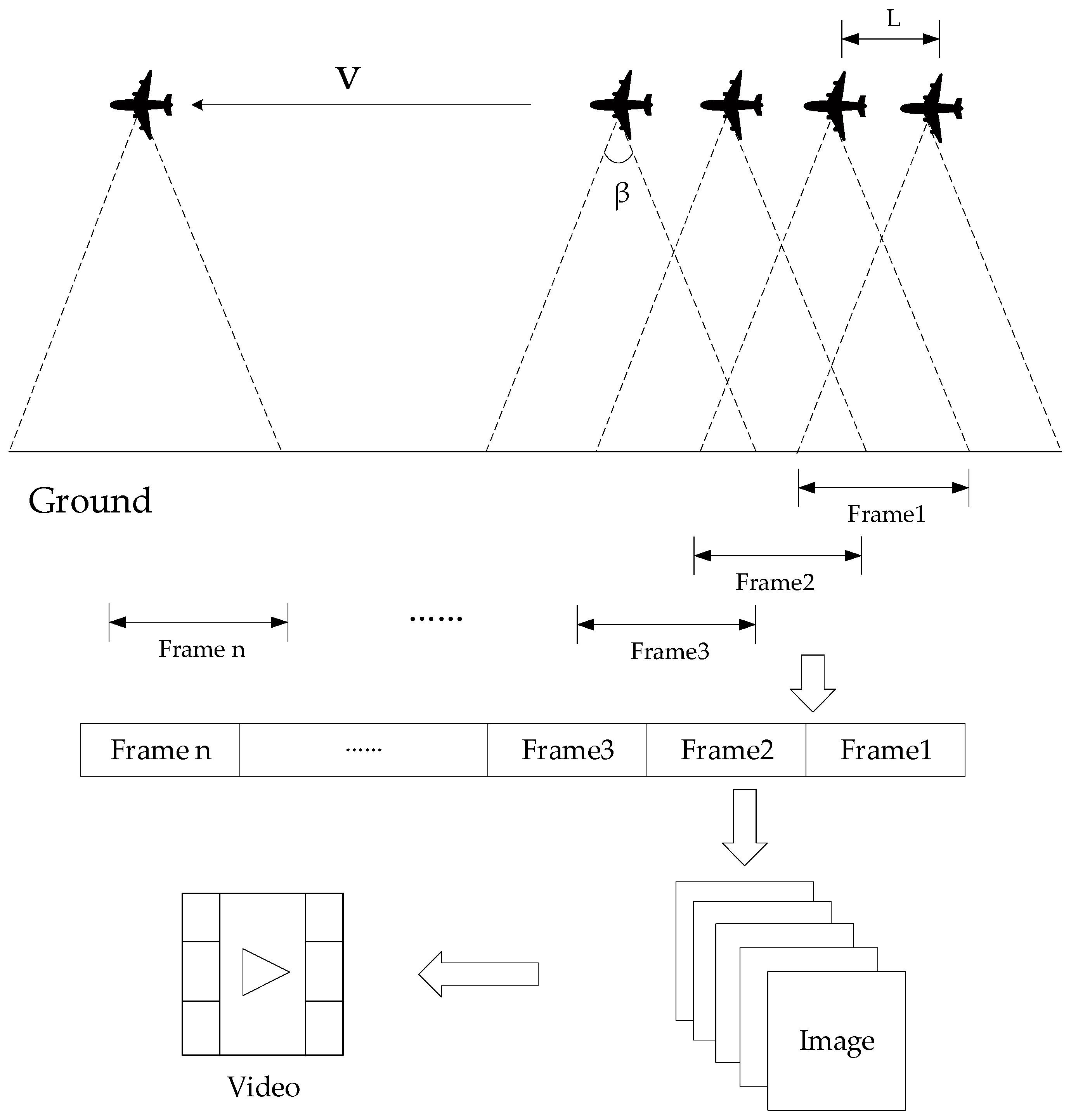
Figure 1. Imaging mode of the video SAR.
Remotesensing 16 00191 g001
Figure 2. Flowchart of the high-frame-rate ViSAR real-time imaging algorithm.
Remotesensing 16 00191 g002
Figure 3. Flowchart of implementing the range-Doppler algorithm on an embedded GPU.
Remotesensing 16 00191 g003
Figure 4. Flowchart of the map drift algorithm.
Remotesensing 16 00191 g004
Figure 5. Flowchart of error estimation.
Remotesensing 16 00191 g005
Figure 8. Unaligned and unpinned memory access.
Remotesensing 16 00191 g008
Figure 9. The embedded GPU ViSAR high-frame-rate imaging system.
Remotesensing 16 00191 g009
Figure 10. Atmospheric attenuation map.
Remotesensing 16 00191 g010
Figure 11. Real-time imaging results of the ViSAR based on the Jetson AGX Orin platform: (a) first-frame image; (b) second-frame image; (c) third-frame image; (d) fourth-frame image; (e) fifth-frame image; (f) sixth-frame image; (g) seventh-frame image; (h) eighth-frame image; (i) ninth-frame image.
Remotesensing 16 00191 g011aRemotesensing 16 00191 g011b
Figure 12. One-frame imaging results of the ViSAR: (a) Jetson AGX Orin; (b) MATLAB.
Remotesensing 16 00191 g012
Figure 13. ViSAR imaging differences.
Remotesensing 16 00191 g013
Table 1. Hardware system parameters of the experimental platforms.
SpecificationJetson AGX OrinJetson NanoJetson TX2RTX 2060 Max-Q
GPU2048-core
NVIDIA Ampere
128-core
NVIDIA Maxwell
256-core
NVIDIA Pascal
1920-core NVIDIA Turing
CPU12-core ARM
[email protected] GHz
4-core ARM
[email protected] GHz
2-core [email protected] GHz
4-core ARM [email protected] GHz
8-core Intel [email protected] GHz
Memory32 GB 256-bitLPDDR5 204.8 GB/s4 GB 64-bit LPDDR4 25.6 GB/s8 GB 128-bit LPDDR4 59.7 GB/s6 GB 192-bit GDDR6 264.0 GB/s
GPU
Frequency
1.3 GHz922 MHz1.3 GHz1185 MHz
Power
consumption
60 W5 W15 W<230 W
Table 2. Comparison results of test images.
PSNRSSIM
Image48.1308 dB0.9652
Table 3. Processing times of ViSAR imaging on different platforms.
Processing PlatformJetson AGX OrinRTX 2060 Max-QJetson NanoJetson
TX2
Core i7-10875H CPU
Processing time required by the RD algorithm0.012 s0.014 s0.163 s0.126 s0.348 s
Processing time required by the MD algorithm0.123 s0.172 s1.825 s1.432 s5.022 s
Total time consumption0.135 s0.186 s1.988 s1.558 s5.370 s
Disclaimer/Publisher’s Note: The statements, opinions and data contained in all publications are solely those of the individual author(s) and contributor(s) and not of MDPI and/or the editor(s). MDPI and/or the editor(s) disclaim responsibility for any injury to people or property resulting from any ideas, methods, instructions or products referred to in the content.