Article

A NavCom Signal Authentication Scheme Based on Twice Two-Way Satellite Time Transfer

School of Electronic Science, National University of Defense Technology, Changsha 410073, China
*
Author to whom correspondence should be addressed.
Remote Sens. 2024, 16(1), 10; https://doi.org/10.3390/rs16010010
Submission received: 22 October 2023 / Revised: 13 December 2023 / Accepted: 15 December 2023 / Published: 19 December 2023
(This article belongs to the Special Issue Space-Geodetic Techniques II)

Abstract

:
Low Earth Orbit (LEO) satellite communication systems typically achieve identity authentication through the encryption and decryption of two-way information, which requires complex key management systems. In contrast, the integration of navigation and communication (NavCom) signals provides novel opportunities for physical observation and authentication solutions due to its measurement functions. This paper introduces a novel signal authentication scheme based on twice two-way satellite time transfer (TWSTT) for LEO satellite systems. It leverages the non-mutated nature of the clock difference to ascertain the legitimacy of the signal by measuring the clock difference of signals at different instances. Unlike traditional authentication methods, this approach directly exploits the temporal and spatial characteristics of the signal, negating the necessity for intricate authorization key systems. Additionally, it adeptly tackles the challenges posed by spoofing interference. The performance analysis indicates that this scheme can achieve a high detection probability for the repeater spoofing signal in the low carrier-to-noise ratio conditions.

1. Introduction

In recent years, the development of Low Earth Orbit (LEO) communication systems has progressed rapidly, with a specific emphasis on integrating navigation enhancement functions. Through the integration of communication and navigation (NavCom) signals [1,2], it would be able to achieve multiple functionalities from a single satellite, leading to resource savings in terms of both orbit and frequency allocation. Moreover, this integration serves to reduce hardware costs while simultaneously enhancing the performance of both communication and navigation performance.
The mainstream navigation satellite system signals are broadcasted with a detailed structure open to the public and processed passively in receivers. While this feature makes satellite navigation an open service with unlimited user capacity, it also brings the threat of spoofing attacks by allowing the construction of counterfeit signals [3]. Since the power grid, financial industries, vehicle autopilots, and other civilian infrastructures rely on the credible position and timing information, these spoofing attacks could severely threaten their security and robustness. Hence, protecting receivers from spoofing attacks is a significant measure to improve the robustness and security of navigation services. Several attempts have been made to address security authentication for navigation signals: (1) Open Service Navigation Message Authentication (OSNMA), a navigation message authentication method adopted by Galileo [4], and (2) Chip-Message Robust Authentication (Chimera), a spreading code encryption method adopted by GPS [5]. However, they still encounter challenges in independently authenticating and authorizing a massive number of users. In addition, they cannot recognize repeater spoofing interference. Repeater spoofing is a method of deceiving attackers by receiving real satellite navigation signals through a repeater and sending spoofing signals to the target after a certain delay. The signal generated by this spoofing method carries exactly the same information, including navigation messages and spreading codes, as the real signal. Thus, traditional security authentication schemes, such as OSNMA and Chimera, cannot recognize repeater spoofing interference.
Actually, researchers primarily focus on achieving navigation functionality within communication signals in the NavCom signals study [6,7,8,9,10,11,12,13,14]. So far, however, very little attention has been paid to treating communication and navigation as a whole, resulting in the full integration of communication and navigation functions having not been thoroughly explored. Furthermore, the potential of leveraging the two-way broadcasting capability of communication signals to enhance the security of navigation signals remains largely untapped.
To address these gaps, this paper proposes a novel NavCom signal authentication scheme for LEO satellite systems based on twice TWSTT. By utilizing the temporal and spatial physical attributes of the signal, this scheme effectively mitigates the risks posed by repeater spoofing interference and significantly enhances the security of the NavCom signal.
This paper is structured as follows: Section 2 presents a twice TWSTT NavCom signal authentication scheme, providing a comprehensive explanation of its fundamental principles and the detailed model of authentication detection. Section 3 analyzes the security performance of this authentication scheme. Finally, Section 4 concludes the paper.

2. A Twice TWSTT NavCom Signal Authentication Scheme

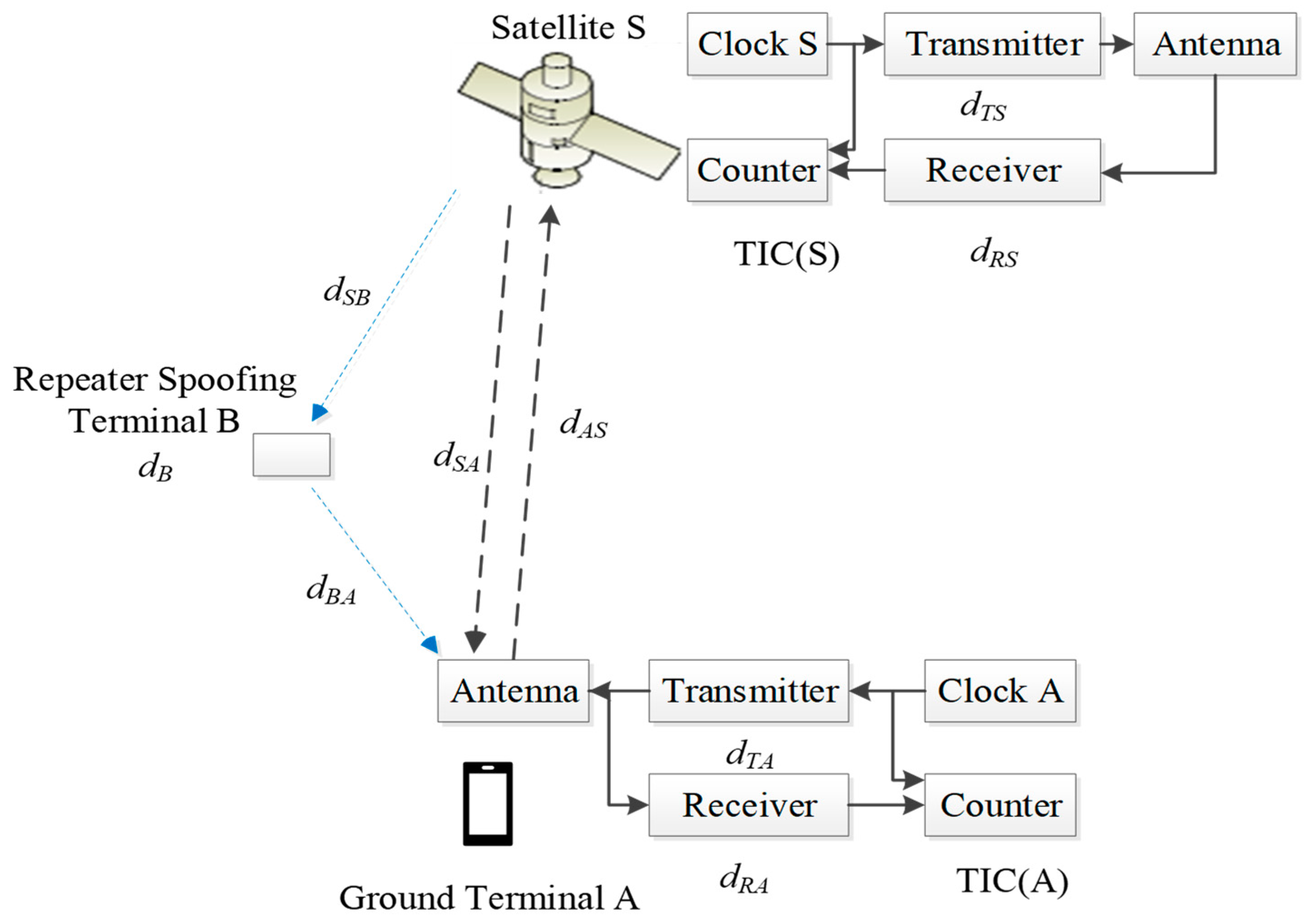
2.1. Fundamental Theory

One of the most accurate remote time synchronization methods is TWSTT [15,16,17,18]. In this mode, the transmission path symmetry enables the propagation delay on the link to be nearly fully offset, which can make the time synchronization reach a high accuracy. Figure 1 illustrates the principle of satellite–earth TWSTT.
As depicted in Figure 1, the computational model of TWSTT can be written as follows:
TIC ( A ) = A S + d Z S + d S A + d Z A + S A
TIC ( S ) = S A + d T A + d A S + d Z S + S S
where TIC ( A ) and TIC ( S ) represent the transmission pseudo-distance values, i.e., the readings of the time interval counter. TIC ( S ) is measured by the satellite and its information is added to the downlink communication signal for transmission to the ground terminal, A and S represent the paper time at the respective stations, d x x represents the propagation delay, and S A and S S are the correction terms for the Sagnac effect. By taking the difference between Equations (1) and (2), we can derive the expression for the clock difference between the ground terminal A and the satellite S as follows:
A S = TIC ( A ) TIC ( S ) 2 + d T A d R A 2 d T S d R S 2 + S A S S 2 + d A S d S A 2
In Equation (3), the first term to the right of the equal sign is the difference between the counter readings of the ground terminal and the satellite, which is the difference between the clock difference measured by the ground terminal and the satellite. The second term corresponds to the difference between the transmission and reception delays of the ground terminal, while the third term denotes the difference between the transmission and reception delays at the satellite end. The fourth term represents the correction for the relativistic effect caused by the rotation of the Earth, i.e., the Sagnac effect, and the fifth term accounts for the difference in the spatial propagation delays for the uplink signal and the downlink signal, including ionospheric delays, tropospheric delays, geometrical path delays, and so on.
The second to fourth terms can be measured or calculated in advance, and the fifth term can be well canceled due to the delay of the upper and lower paths in the very short TWSTT being equal. Thus, Equation (3) can be reduced to Equation (4).
A S = TIC ( A ) TIC ( S ) 2 + d T A d R A 2 d T S d R S 2 + S A S S 2
Therefore, it is only necessary to accurately calibrate and deduct the arrival times of the signals measured by the ground terminals and satellites so that the clock difference measurement can be realized by two-way time comparison.
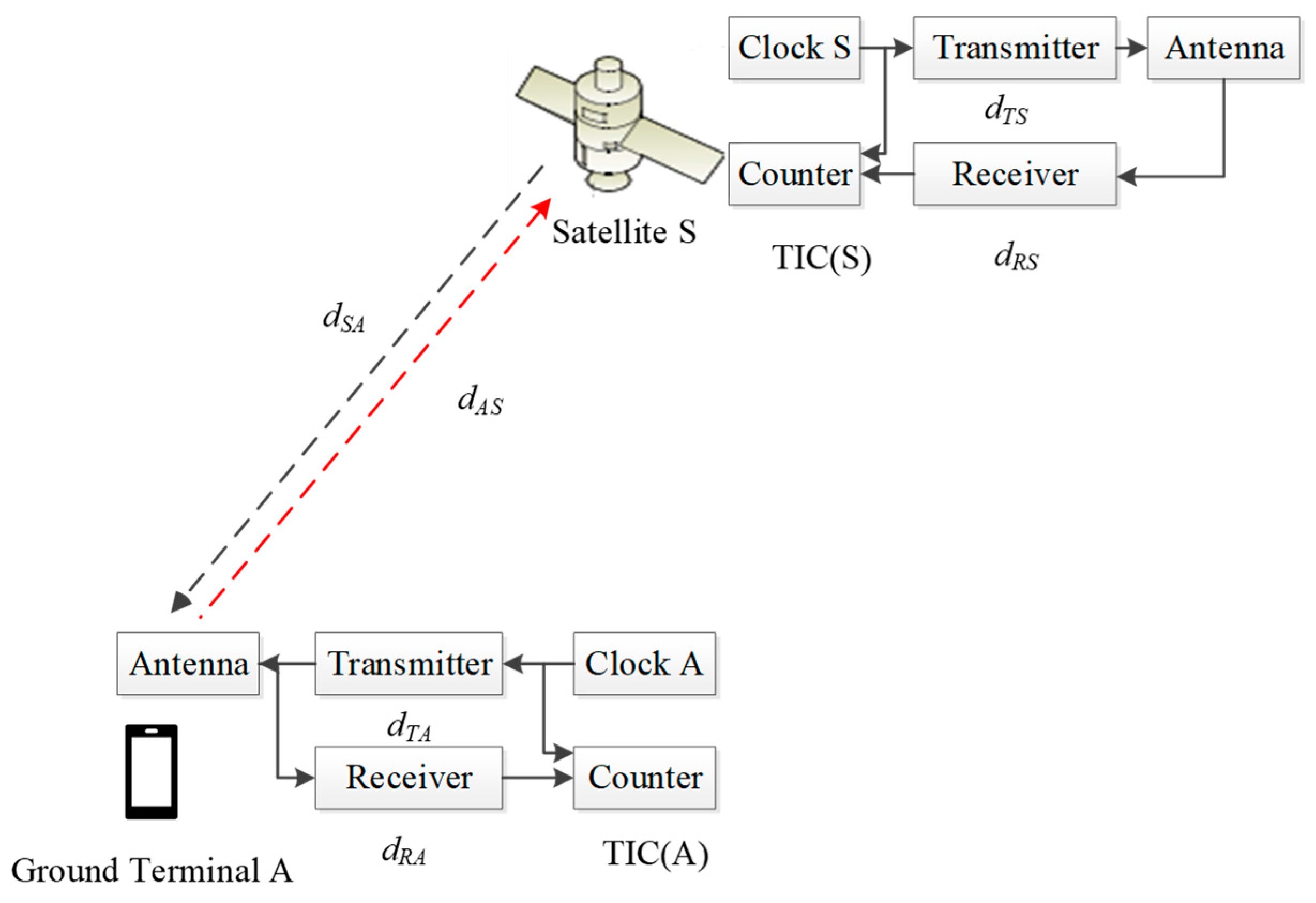
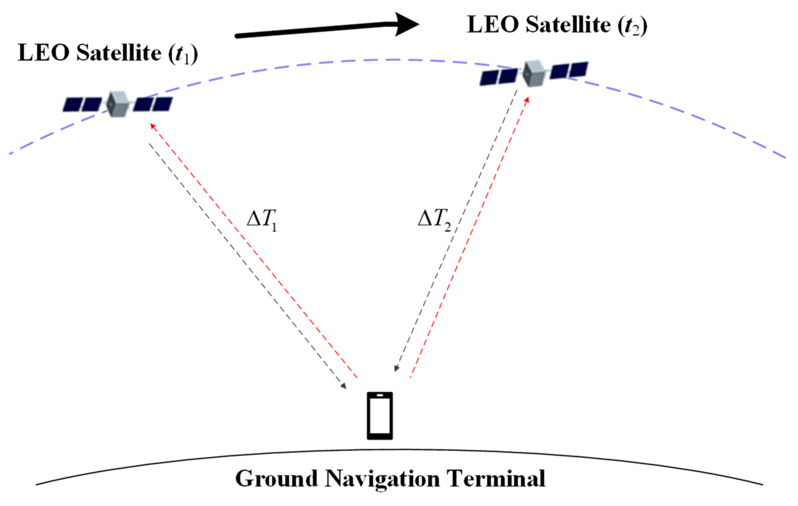
Due to the non-mutated nature of the clock difference, this paper proposes a novel NavCom signal authentication scheme based on twice TWSTT, which involves the user terminal conducting twice separate TWSTT with the same satellite. The scheme can achieve signal security authentication through a comparison of clock difference measurement values. The specific operation procedures are as follows: the user terminal initiates twice two-way authentications at two different moments, t 1 and t 2 , during the satellite’s visibility period. The clock difference measurements obtained from these two authentications are recorded as Δ T 1 and Δ T 2 , respectively.
Figure 2 illustrates a schematic of twice TWSTT. In Figure 2, it can be observed that only the paths of the uplink and downlink signals change during the twice TWSTT processes. Fortunately, the paths of the uplink and downlink signals are equal for the same time transfer process, which can be canceled out. Hence, the twice clock difference measurements obtained should be identical without considering any errors according to Equation (4), i.e., Δ T 1 = Δ T 2 .
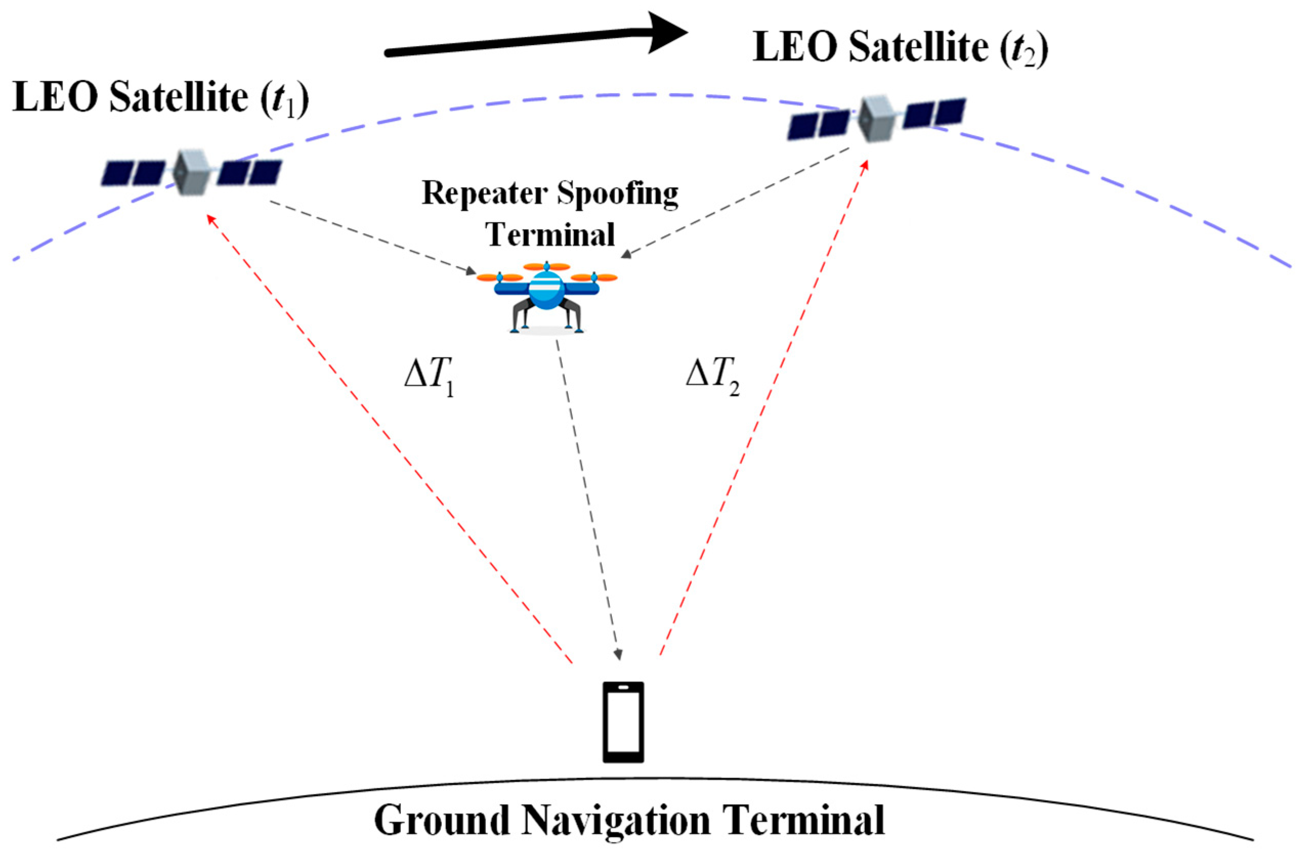
Generally, there is a risk of being spoofed due to the satellite downlink signal being broadcast signals to the ground terminal, mainly including generated spoofing and repeater spoofing interference. For generated spoofing interference signals, information authentication or digital signature can be added to the message of navigation signals, so that the receivers in the satellite or earth can effectively block the unauthenticated signals and prevent the generated spoofing interference. However, it is impossible to block repeater spoofing interference signals in such a way, which is the main problem that the proposed authentication scheme focuses on solving.
Figure 3 illustrates the scenario with repeater spoofing interference, where d B denotes the delay of the spoofing interference signal, d S B represents the delay from satellite S to the repeater spoofing terminal B, and d B A denotes the delay from spoofing terminal B to ground terminal A. As the signal transmitted by ground terminal A to satellite S is pulsed, it is challenging to record and forward it. Therefore, it is the most common form of repeater spoofing interference as depicted in Figure 3.
As a result, the clock difference can be determined by
A S = TIC ( A ) TIC ( S ) 2 + d T A d R A 2 d T S d R S 2 + S A S S 2 + d A S d S B + d B + d B A 2
It is obvious that the clock difference measurements are pulled out of alignment because of the last term in Equation (5). Therefore, ensuring that the clock difference measurements obtained from twice TWSTT are constant is crucial for them to be equal. However, satisfying this condition can be challenging in practice, and the reasons will be discussed below in two different scenarios.
Scenario 1: Ground terminal remains stationary.
Figure 4 depicts the schematic diagram of twice TWSTT in the repeater spoofing interference scenario, where the satellite downlink signals are recorded and forwarded by the spoofing terminal. As shown in Figure 4, the satellite’s position changes during the twice TWSTT processes. When the ground terminal remains motionless, the spoofing terminal can theoretically calculate the trajectory in advance based on the position of the ground terminal and the satellite ephemeris and follow the satellite movement to realize the same value of d AS d SB + d B + d BA in twice measurements. Fortunately, it is challenging to achieve such consistency in practice. Firstly, it is challenging for the spoofing terminal to accurately determine the precise geographic coordinates of the ground terminal. Secondly, there are numerous LEO satellites, and the ground terminal can simultaneously observe multiple satellites. As a result, the spoofing terminal cannot predict the specific moment when the ground terminal will initiate the authentication or the ID of the LEO satellites involved. Thirdly, it requires a high level of control accuracy for the flight platform carrying the spoofing terminal, even if the operation trajectory is calculated in advance. Any slight deviation can disrupt the spoofing scheme, making it infeasible to achieve the desired consistency in the measurements.
Scenario 2: Ground terminal is in motion.
It becomes even more difficult to achieve consistency in twice measurements if the ground terminal is also in motion. This is because the trajectory of the ground terminal cannot be precisely predicted in advance, which makes it impossible for the spoofing terminal to calculate the running trajectory ahead of time.
In summary, it is difficult to keep the two clock difference measurements consistent according to the analysis of scenario 1 and scenario 2. In such scenarios, the ground terminal can ascertain the presence of repeater spoofing interference, as the inconsistency in the measurements serves as an indication.
However, the previous analysis did not consider measurement errors, which can occur in real situations. The measurement of signal arrival time at the ground terminal can be subject to biases in twice TWSTT process. These biases may result in the same value of Δ T 1 and Δ T 2 when there are repeater spoofing interference signals, potentially leading to successful spoofing. Therefore, it is necessary to conduct further analysis and consider measurement errors when studying real scenarios [19].

2.2. Signal and Detection Model

The earlier analysis indicates that the accuracy of the clock difference from the twice TWSTT is significant for security authentication capabilities. As such, it is essential to analyze the error associated with clock difference measurement accuracy.
Equation (3) reveals that the accuracy of clock difference measurement is influenced by four main factors: hardware device time delay difference, Sagnac effect error, space propagation time delay difference, and signal arrival time measurement error [20].
(1) Hardware device time delay difference:
The hardware device time delay error mainly includes the hardware processing time delay error, the hardware storage time delay error, and the hardware variation error with temperature. From the literature [20], these errors add up to about 80 ps.
(2) Sagnac effect error:
The Sagnac effect error is a result of the signal transmission process and arises from the continuous rotation of the Earth, which is caused by the changing relative distance between the ground terminal and the satellite. This error can be calculated using calibration formulas and is typically on the order of 1 ps [21].
(3) Space propagation time delay difference:
The space propagation delay difference includes ionospheric delay, tropospheric delay, and geometric path delay. Among them, the ionospheric time delay difference is 10 ps, the tropospheric time delay can be negligible after correction by the tropospheric delay model, and as for the geometric path delay, TWSTT can be accomplished within 10 ms due to the low orbital altitude of LEO satellites so that the uplink and downlink can be regarded as completely symmetrical between the satellite and the ground terminal. Therefore, the space propagation time delay difference is about 10 ps [22].
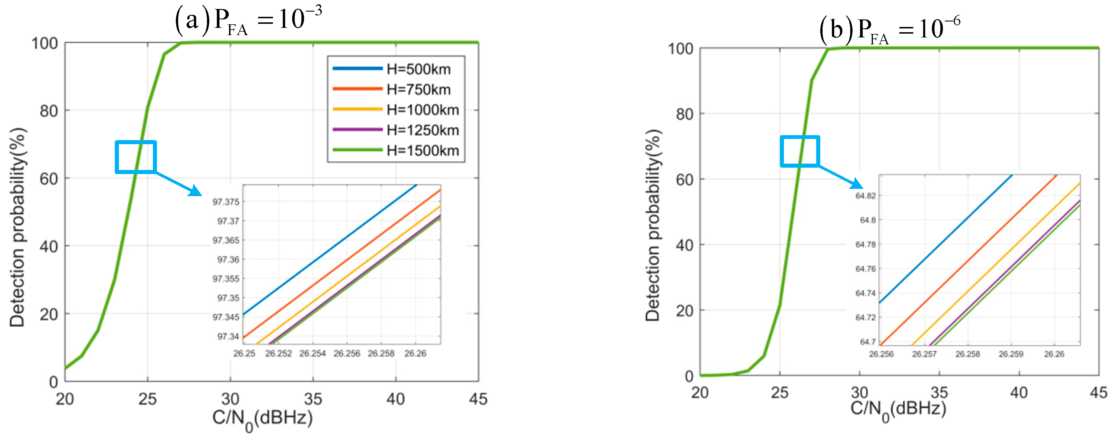
(4) Signal arrival time measurement error:
Without loss of generality, a detailed analysis using conventional BPSK navigation signals as an example is presented in this section. The measurement of signal arrival time can be performed either through carrier phase measurement or code phase measurement for receivers. The receiver typically utilizes code phase measurement, due to the long convergence time required for carrier phase measurement, and the TWSTT usually uses a short burst signal. In this case, assuming the receiver uses a code-ring discriminator with a noncoherent pre-subtracted post-power method, we can calculate the mean square error of the code phase measurement in terms of pseudo-code code slices using Equation (6) [23]:
σ t D L L = B L 2 C / N 0 D 1 + 2 ( 2 D ) T coh   C / N 0
where B L is the loop noise bandwidth, T coh is the coherence accumulation time, D is the early-late correlator spacing, and C / N 0 is the CNR. If the chip duration is T C   , then the mean square deviation of time measurement error σ t i m e can be determined by
σ t i m e = σ t D L L × T C
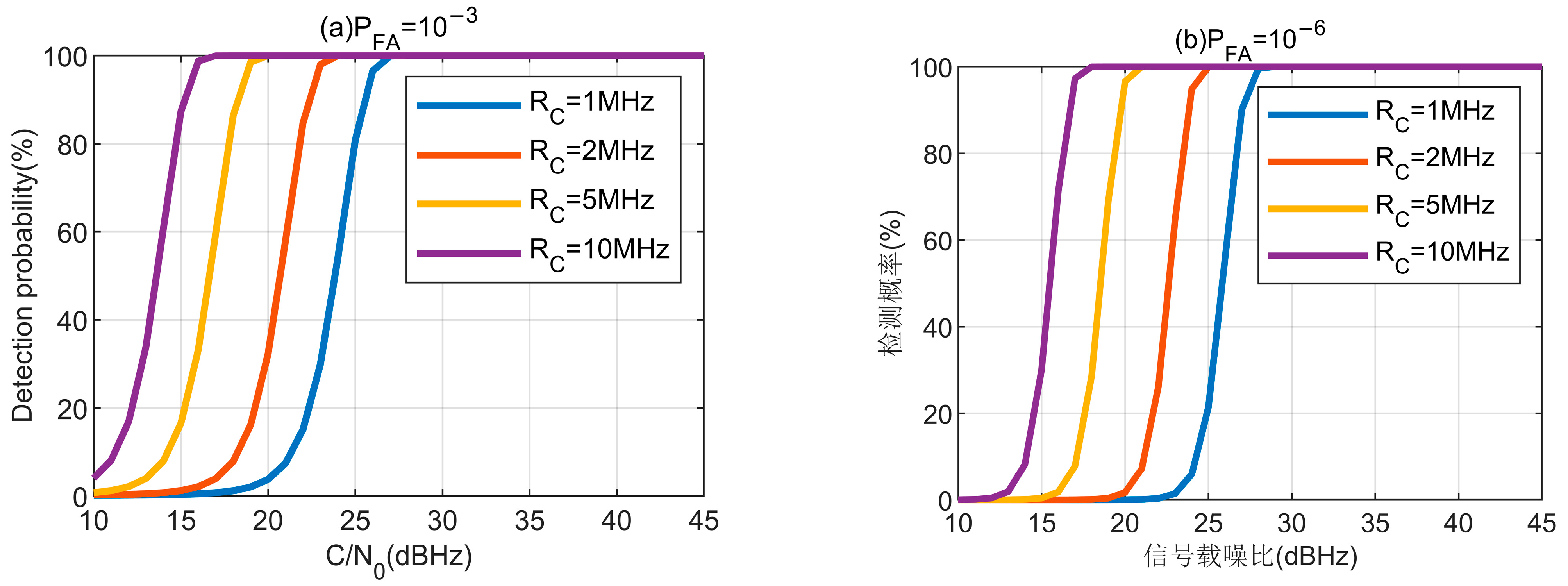
Let the chip rate of the BPSK navigation signal be 1.023 MHz, then Tc = 1/1023 ms, B L = 1 Hz, T coh   = 1 ms, D = 1 chip, and C / N 0 = 40 ~ 60 
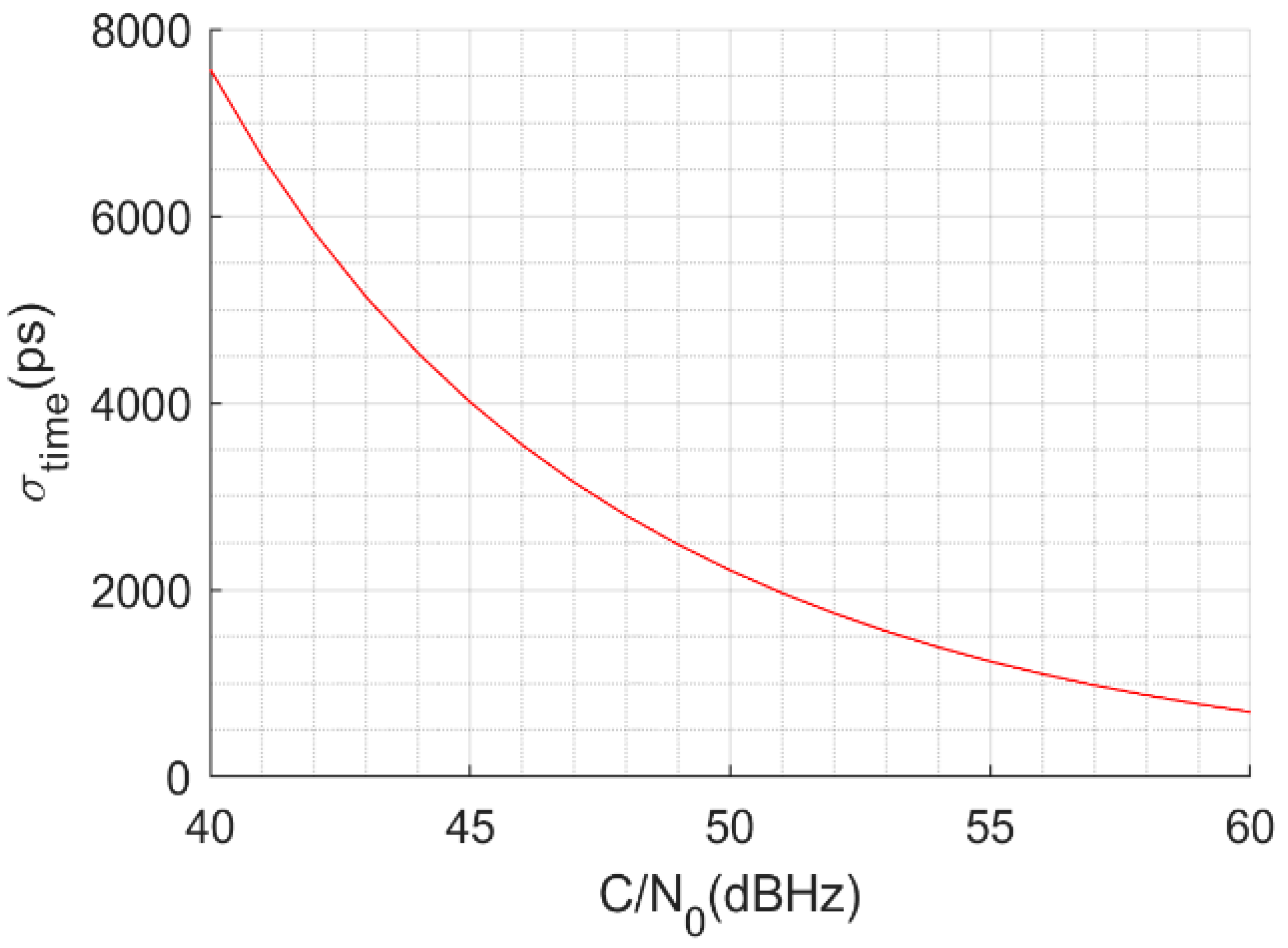
dBHz; this can be seen the variation trend of concern in Figure 5.
Figure 5 is only the signal arrival measurement time error of the ground terminal, the signal arrival measurement time error of the satellite can be calculated similarly, and it should be in the same order of magnitude.
From the above analysis, it can be seen that the hardware device time delay difference, the Sagnac effect error, and the space propagation time delay difference together do not exceed 100 ps at most, which is much smaller than the signal arrival time measurement error and can be ignored. Therefore, when there is no repeater spoofing interference signal, it can be obtained that the measurement errors of TIC ( A ) and TIC ( S ) obey the probability density distributions shown in Equation (8).
TIC ( A ) ~ N 0 , T C , A 2 σ t D L L A 2 TIC ( S ) ~ N 0 , T C , S 2 σ t D L L S 2
where T C , A and σ t D L L A are the pseudo-code width and mean square deviation of the downlink signal’s code phase measurement error, and T C , S and σ t D L L S are the pseudo-code width and mean square deviation of the uplink signal’s code phase measurement error, respectively. Then, the clock difference measurement Δ T will obey the probability density distribution shown in Equation (9), where T is the true value of the clock difference.
Δ T ~ N T , T C , A 2 σ t D L L , A 2 + T C , S 2 σ t D L L , S 2
When there is no repeater spoofing interference signal, the two clock difference measurements Δ T 1 and Δ T 2 obey the probability density distribution shown in Equation (10).
Δ T 1 ~ N T , T C , A 2 σ t D L L , A 2 + T C , S 2 σ t D L L , S 2 Δ T 2 ~ N T , T C , A 2 σ t D L L , A 2 + T C , S 2 σ t D L L , S 2
For further analysis, we define the certified detection volume of this method as the difference between two clock difference measurements, as shown in Equation (11).
R outh   = Δ T 1 Δ T 2
Therefore, when there is no repeater spoofing interference signal, the authentication detection volume will obey the probability density distribution shown in Equation (12).
H 1 : R outh   ~ N 0 , 2 T C , A 2 σ t D L L , A 2 + 2 T C , S 2 σ t D L L S 2
When the repeater spoofing interference signal is present, there will be an offset in the clock difference due to the spoofing signal, which can be denoted as T delay , and T delay = d A S d S B + d B + d B A 2 . At this point, the two clock difference measurements Δ T 1 and Δ T 2 will obey the probability density distribution shown in Equation (13).
Δ T 1 ~ N T + T delay , 1 , T C , A 2 σ t D L L , A 2 + T C , S 2 σ t D L L , S 2 Δ T 2 ~ N T + T delay , 2 , T C , A 2 σ t D L L , A 2 + T C , S 2 σ t D L L , S 2
where T delay , 1 and T delay , 2 represent the clock difference offsets of the twice TWSTT, respectively. Therefore, when the repeater spoofing interference signal is present, the authentication detection volume will obey the probability density distribution shown in Equation (14).
H 0 : R outh   ~ N Δ T delay   , 2 T C , A 2 σ t D L L , A 2 + 2 T C , S 2 σ t D L L S 2
where Δ T delay   = T delay , 1 T delay , 2 . Owing to Δ T delay   not being a fixed value, its probability distribution must be analyzed. Due to once TWSTT time being relatively short and the ground terminal being fixed in most scenarios, it is assumed that the positions of the spoofing terminal and the ground terminal remain unchanged during the twice TWSTT processes, then Δ T delay   can be rewritten as Equation (15).
Δ T delay   = d AS , 2 d SB , 2 + d B + d BA 2 d AS , 1 d SB , 1 + d B + d BA 2 = d AS , 2 d AS , 1 d SB , 2 d SB , 1 2
where d AS , 1 and d SB , 1 represent the paths from satellite S to ground terminal A and from satellite S to spoofing terminal B in the first TWSTT, respectively. Similarly, d AS , 2 and d SB , 2 represent the paths from satellite S to ground terminal A and from satellite S to spoofing terminal B in the second TWSTT, respectively.
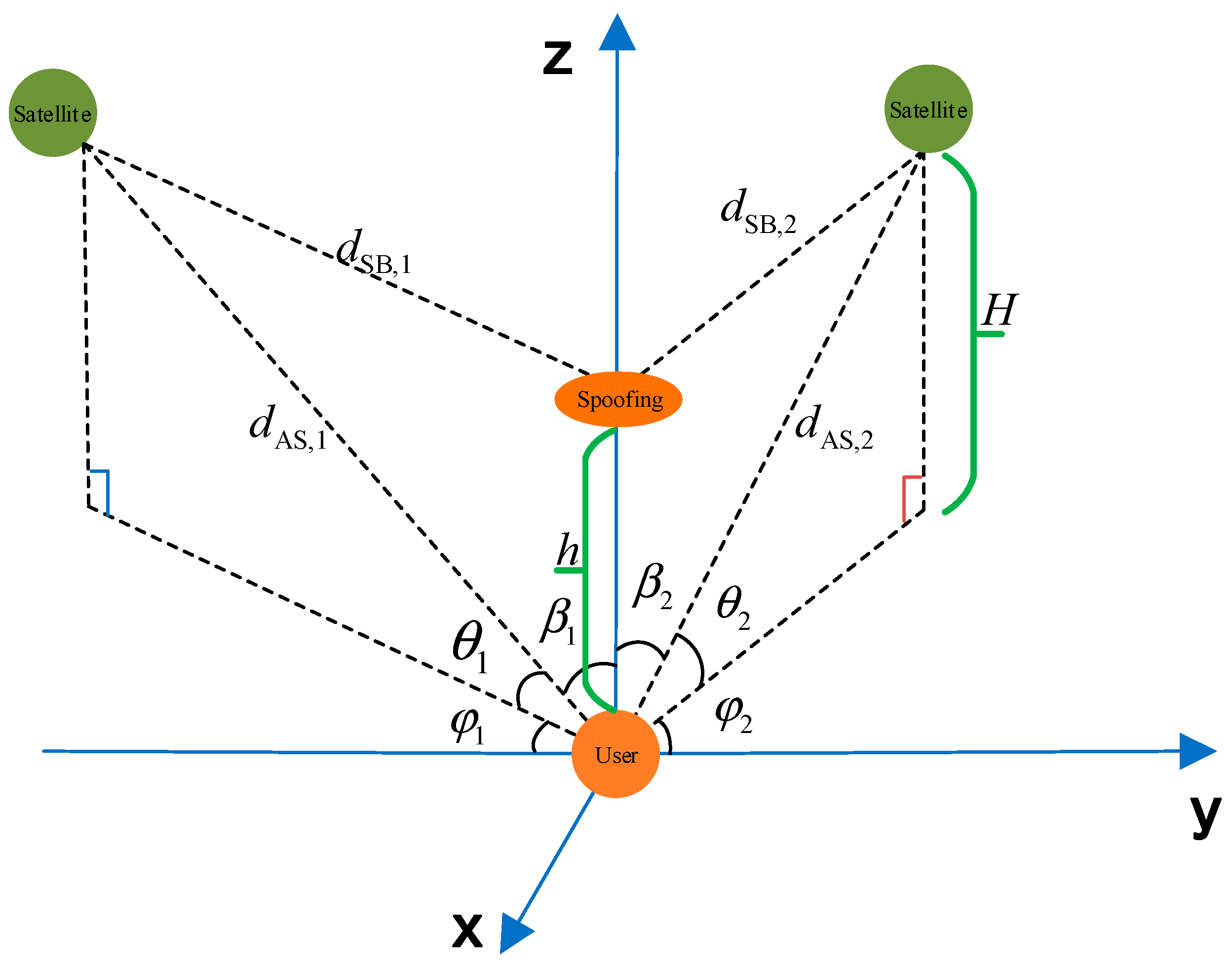
If the spoofing terminal is directly positioned above the ground terminal, the spatial propagation loss of the spoofing signal would be minimized, making it more effective in suppressing the genuine signal. Consequently, this method is considered the most cost-effective way for the spoofing terminal to carry out its deception. To facilitate a more accurate modeling of this scenario, we can establish a spatial geometry model as depicted in Figure 6.
In the geometric relationship shown in Figure 6, we denote H as the vertical distance between the LEO satellite and the user terminal, and h as the vertical distance between the spoofing terminal and the user terminal. Based on this geometry, we can derive the following relationship, where c represents the speed of light.
c d AS , 1 = H / sin θ 1 c 2 d AS , 1 2 + h 2 2 h c d AS , 1 cos β 1 = c 2 d SB , 1 2 θ 1 + β 1 = 90 ° c d AS , 2 = H / sin θ 2 c 2 d AS , 2 2 + h 2 2 h c d AS , 2 cos β 2 = c 2 d SB , 2 2 θ 2 + β 2 = 90 °
Substituting Equation (16) into Equation (15) transforms the expression as follows:
Δ T delay = H sin θ 2 H sin θ 1 2 c H sin θ 2 2 + h 2 2 H h H sin θ 1 2 + h 2 2 H h 2 c
It can be seen from Equation (17) that Δ T delay is a function using H , h , θ 1 , and θ 2 . Where h is determined by the spoofing terminal, for example, the UAV flight altitude is usually 1~15 km, and H , θ 1 , and θ 2 are determined by the satellite position and the user terminal position; when the user terminal is fixed, the values of θ 1 and θ 2 can be changed by changing the moment of initiating the authentication. Therefore, it is necessary to analyze the optimal elevation angle and initiation timing for authentication at the user terminal. By performing calculations, 
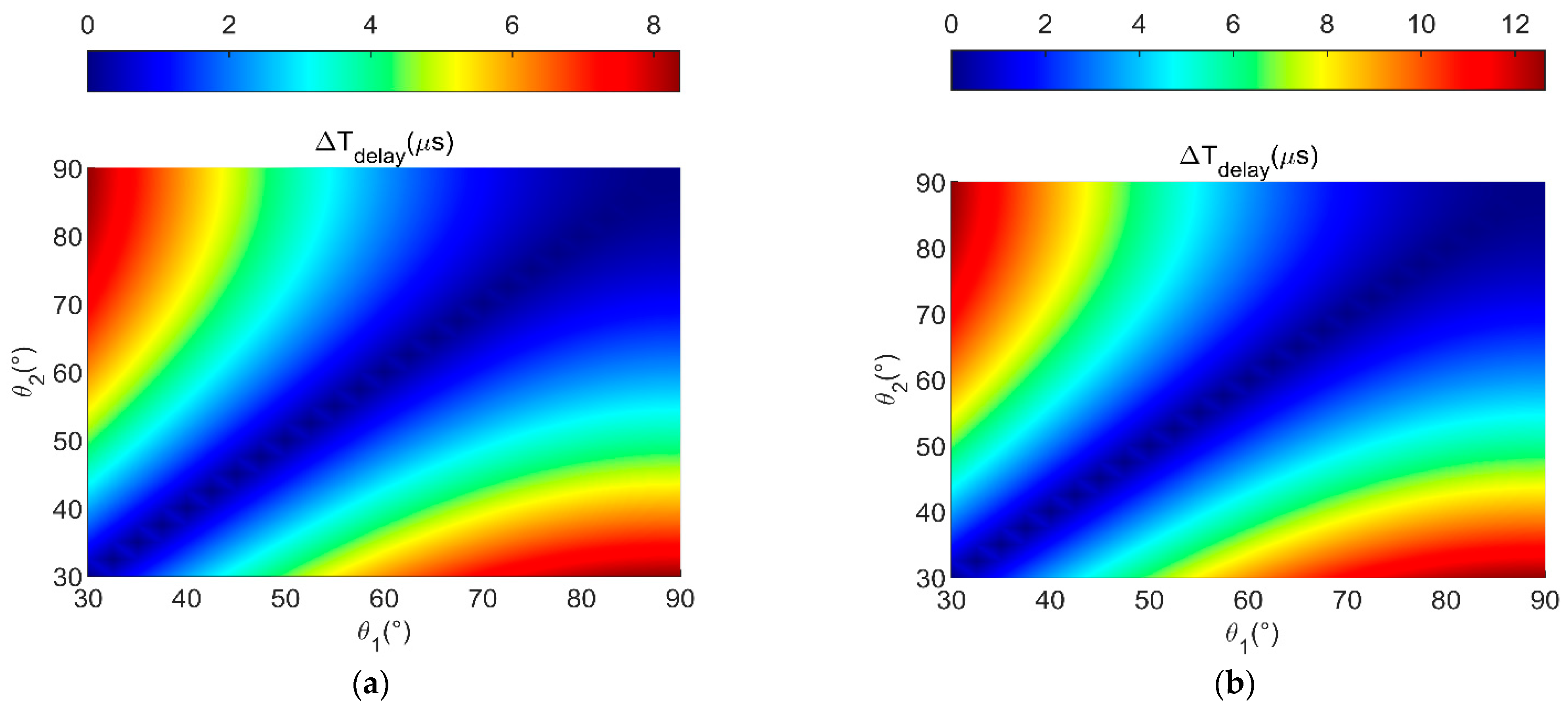
Figure 7 shows the relationship between Δ T delay and θ 1 with θ 2 when different combinations of H and h are used. The visible elevation angle of the satellite is generally required to be larger than 15°. To ensure adequate visibility between the satellite and the user terminal, the range of θ 1 and θ 2 inthe figure is set from 30° to 90°.
From Figure 7, we can draw the following two conclusions:
(1)
When the vertical distance between the LEO satellite and the user terminal H and the vertical distance between the spoofing terminal and the user terminal h are fixed, and the elevation angles ( θ 1 and θ 2 ) of the user terminal to the satellite are equal, it results in Δ T delay being 0. This indicates that the user terminal can successfully be spoofed by a spoofing terminal.
(2)
The larger the difference between θ 1 and θ 2 , the greater the value of Δ T delay . In this context, a higher value of Δ T delay indicates a lower likelihood of being spoofed by the spoofing terminal.
Therefore, in order to ensure that this authentication scheme can perform optimally, the moment when the user terminal initiates the authentication request needs to meet the requirement of maximizing the difference between the values of θ 1 and θ 2 . Without loss of generality, we set θ 1 = 30 o , θ 2 = 90 o or θ 1 = 90 o , θ 2 = 30 o . As users can obtain satellite ephemeris through communication signals in advance, they can predict the launch angle and launch time in advance.
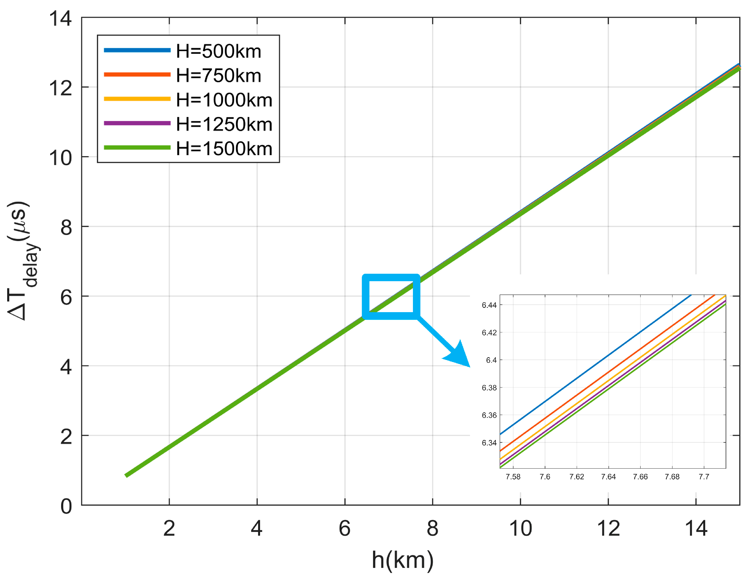
Figure 8 illustrates the variation trend of Δ T delay versus h and H when θ 1 = 30 o and θ 2 = 90 o . From Figure 8, we can draw the following conclusions:
(1)
When θ 1 , θ 2 , and H are fixed during user terminal authentication, it can be observed that the smaller the h , the smaller Δ T delay becomes, resulting in a higher likelihood of successful spoofing.
(2)
When θ 1 , θ 2 , and h are fixed, the larger H and the smaller Δ T delay become, the easier it is to spoof successfully.
(3)
H has a relatively small effect on the Δ T delay . In contrast, h has a larger effect on the Δ T delay .
To analyze the impact of h and H on Δ T delay more effectively, we substitute the optimal elevation angles into Equation (17); Δ T delay   can be rewritten as follows:
Δ T delay   = 2 H 4 H 2 + h 2 2 H h h 2 c
Owing to the user terminal already possessing the satellite ephemeris in advance, the value of H is known to the user terminal. Therefore, we can consider Δ T delay as a function solely dependent on h . Through numerical calculations and fitting analysis, we establish the following relationship:
Δ T delay   ( h ) ~ U 4.16 × 10 22 h 2 1.22 × 10 15 h + 8.34 × 10 7 , 9.48 × 10 20 h 2 2.77 × 10 13 h + 1.28 × 10 5
The fitted correlation coefficient of Equation (19) is 0.9923, indicating a strong correlation between the variables h and Δ T delay . Additionally, the mean squared error of the fitting is 1.294 ps, suggesting that the Equation (19) provides an accurate characterization of the original function. To investigate the performance limits of the proposed NavCom signal authentication scheme, the worst-case spoofing scenario is considered. In this scenario, we assume that Δ T delay takes its minimum value, and then the Equation (14) can be transformed into the following:
H 0 : R outh   ~ N min Δ T delay   , 2 T C , A 2 σ t D L L , A 2 + 2 T C , S 2 σ t D L L S 2
where min Δ T delay = 4.16 × 10 22 h 2 1.22 × 10 15 h + 8.34 × 10 7 . As a result, the hypothesis testing for the certified detection volume of this method is shown below:
H 0 : R outh   ~ N min Δ T delay , 2 T C , A 2 σ t D L L , A 2 + 2 T C , S 2 σ t D L L S 2 H 1 : R outh   ~ N 0 , 2 T C , A 2 σ t D I L   A 2 + 2 T C , S 2 σ t D L L S 2
When the false alarm probability of the constant false alarm detection is denoted as PFA, the detection threshold R th can be determined by Equation (22).
R th P F A = min Δ T delay 2 T C , A 2 σ t D L L , A 2 + 2 T C , S 2 σ t D L L , S 2 Q 1 P F A
where Q ( x ) = x + 1 2 π exp 1 2 t 2 d t is the right-tailed function of the standard normal distribution. At this point, the detector for signal authentication can be defined as Equation (23).
R outh   = Δ T 1 Δ T 2 f detect   = H 0 , R outh   > R t h P F A H 1 , R outh   R th P F A
Specifically, after the calculation of the clock difference measurements from twice TWSTT, the magnitude of the difference is compared against the detection threshold to determine whether the difference exceeds this threshold.

3. Performance Analysis

The evaluation of the navigation signal security authentication capability encompasses three main aspects: security, authentication efficiency, and cost [24]. These aspects will be analyzed sequentially as follows.

3.1. Security

To mitigate generated spoofing interference, the authentication scheme can enhance information authentication or employ digital signatures on the navigation signal messages. This effectively blocks unauthenticated signals at the receiver on the ground, thus preventing generated spoofing interference. There are well-established methods to counter generated spoofing interference in the field of navigation, such as the navigation message authentication method OSNMA and the spreading code encryption method Chimera. However, these methods are not the central focus of the proposed authentication scheme, so they will not be evaluated here.
For repeater spoofing interference, it can be seen from the analysis in the previous section that, in order to optimize the detection performance of the present NavCom signal authentication scheme, it is necessary to increase the magnitude between the twice TWSTT signal transmitting elevation angles as much as possible. It is recommended to set them to 30° and 90°, respectively. When the values of the two transmitting elevation angles are fixed, the detection probability is affected by the vertical distance between the satellite and the user terminal, the signal CNR, the pseudo-code rate, the code-ring parameters, and the false alarm probability.
Let the spreading code rate of both uplink and downlink signals be 1.023 MHz, the loop noise bandwidth be 1 Hz, the coherence accumulation time be 1 ms, and the front and rear correlator spacing be 1 chip. When the false alarm probability is taken as 10−3 and 10−6, respectively, the relationship between the detection probability and the signal CNR of the proposed authentication scheme at different satellite-to-user vertical distances is shown in Figure 9.
As shown in Figure 9, the authentication scheme proposed in this paper can achieve highly reliable authentication even with a low signal CNR and can effectively resist repeater spoofing interference. Additionally, the proposed method is minimally impacted by the vertical distance between the satellite and the user terminal, making this factor negligible.
To further analyze the effect of the spreading code rate on the system performance, let the vertical distance between the satellite and the user terminal be 1000 km, and keep the code loop parameters of the receiver unchanged. Figure 10 illustrates the relationship between the detection probability and signal CNR of the proposed method at different spreading code rates. This relationship is graphed for two cases of false alarm probability, specifically, 10−3 and 10−6.
When examining Figure 10, what is striking about the figure is that the NavCom signal authentication scheme exhibits enhanced reliability as the spreading code rate increases. For instance, when the spreading code rate is set to 1.023 MHz, the signal CNR of 28 dBHz is necessary to attain a detection probability of 100%. Surprisingly, when the spreading code rate is increased to 10.23 MHz, a considerably lower signal CNR of 18 dBHz is sufficient to achieve the same 100% detection probability.
In summary, the analysis results demonstrate that the proposed authentication scheme exhibits highly reliable authentication even with a low signal CNR. Moreover, it effectively addresses repeater spoofing interference, further enhancing its robustness and security.

3.2. Authentication Efficiency

Since the time to complete once TWSTT is much shorter than the time interval between twice TWSTT, the authentication time of the present authentication scheme may be equal to the time interval between twice TWSTT. Based on the aforementioned analysis, it is evident that the optimal authentication elevation angles for the user terminal are determined to be 30° and 90°. Consequently, the authentication time can be estimated as the duration when the elevation angles of both the satellite and the user terminal change by 60°. Additionally, it should be noted that the movement speed of the satellite is closely linked to its altitude in orbit, which further affects the authentication time. Assuming that the altitude of the user terminal is 0 m and the orbital altitude of the LEO satellites is 500~1500 km, Figure 11 shows the authentication time with different satellite orbital altitudes
Figure 11 clearly illustrates that there is a positive correlation between satellite orbital altitude and the required authentication time, resulting in longer authentication times at higher altitudes. The authentication times vary between approximately 2 to 6 min.

3.3. Cost

The cost of the proposed authentication scheme mainly consists of the cost associated with the third-party link, computation, and storage complexities of both the ground terminal and the satellite.
However, owing to this authentication scheme being designed to operate within a NavCom integrated system, only the arrival time of the satellite-measured signal needs to be transmitted to the user terminal via the communication component, thereby eliminating the need for any third-party link cost.
Furthermore, the receiver is responsible for fulfilling the ranging function, thus minimizing any additional cost requirements. As a result, the cost of this authentication scheme primarily involves the satellite’s ability to measure the uplink signal accurately.
This scheme utilizes physical layer security for authentication, because there is no need for key distribution and security, and the key management system is greatly simplified by directly utilizing the motion characteristics of low-orbit satellites and the slow-varying characteristics of clock differences.

4. Conclusions

In this paper, a novel secure authentication NavCom authentication scheme is proposed for LEO navigation-communication integration systems, and the meaningful works to emerge from this study are as follows: (1) This paper analyzes the advantages of integrating NavCom signals in LEO systems, as well as the limitations of traditional security authentication methods, which can be served as performance guidelines for designing a reliable NavCom authentication scheme for LEO satellite systems. (2) For those guidelines, a novel NavCom signal authentication scheme based on twice TWSTT is proposed, where the user terminal initiates twice TWSTT to the same satellite and realizes security authentication by comparing the twice clock difference measurement. Owing to the relative position of the satellite and the user terminal changing rapidly, it is impossible to ensure that the two clock difference measurements are equal when the repeater spoofing interference signal is present, so the existence of spoofing can be determined easily. (3) Overall, the analysis shows that the proposed authentication scheme can achieve highly reliable authentication with low signal CNR. Moreover, it can effectively address repeater spoofing interference, greatly improve the security of signals, and make full use of the communication and measurement functions of the NavCom signal at a low cost.

Author Contributions

Methodology, X.T.; validation, S.W., J.L. and F.W.; writing—original draft preparation, X.T. and S.W.; writing—review and editing, J.L. and S.W.; supervision, F.W. All authors have read and agreed to the published version of the manuscript.

Funding

This research was funded by the National Natural Science Foundation of China (Grant No. U20A0193 and No. 62003354).

Data Availability Statement

The data presented in this study are available on request from the corresponding author. The codes presented in this study are available on request from the corresponding author.

Conflicts of Interest

The authors declare no conflict of interest.

References

  1. Ruggieri, M. Next Generation of Wired and Wireless Networks: The NavCom Integration; Kluwer Academic Publishers: Dordrecht, The Netherlands, 2006. [Google Scholar]
  2. Ji, J.; Liu, Y.; Chen, W.; Wu, D.; Lu, H.; Zhang, J. A Novel Signal Design and Performance Analysis in NavCom Based on LEO Constellation. Sensors 2021, 21, 8235. [Google Scholar] [CrossRef] [PubMed]
  3. Yuan, M. Security Authentication Technologies for GNSS Signals; National University of Defense Technology: Changsha, China, 2022. [Google Scholar]
  4. Gamba, M.; Nicola, M.; Motella, B. Computational Load Analysis of a Galileo OSNMA-Ready Receiver for ARM-Based Embedded Platforms. Sensors 2021, 21, 467. [Google Scholar] [CrossRef] [PubMed]
  5. Gamba, M.; Nicola, M.; Motella, B. GPS Chimera: A Software Profiling Analysis. In Proceedings of the 33rd International Technical Meeting of the Satellite Division of the Institute of Navigation, Online, 22–25 September 2020. [Google Scholar]
  6. Diglys, D. The Use of Characteristic Features of Wireless Cellular Networks for Transmission of GNSS Assistance and Correction Data; IEEE: New York, NY, USA, 2010. [Google Scholar]
  7. Liang, J. Investigation on Iridium STL Positioning Method; Huazhong University of Science and Technology: Wuhan, China, 2019. [Google Scholar]
  8. Liu, X.; Liang, M.; Morton, Y.; Closas, P.; Zhang, T.; Hong, Z. Performance evaluation of MSK and OFDM modulations for future GNSS signals. GPS Solut. 2014, 18, 163–175. [Google Scholar] [CrossRef]
  9. Diez, J.; Castro, D.; Palomo, J.M.; Tossaint, M. Integrated navigation and communication system based on OFDM. In Proceedings of the 2010 5th ESA Workshop on Satellite Navigation Technologies and European Workshop on GNSS Signals and Signal Processing (NAVITEC), Noordwijk, The Netherlands, 8–10 December 2010. [Google Scholar]
  10. Mensing, C.; Dammann, A. Positioning with OFDM-based communications systems and GNSS in critical scenarios. In Proceedings of the 2008 5th Workshop on Positioning, Navigation and Communication, Hannover, Germany, 27 March 2008; IEEE: New York, NY, USA, 2008. [Google Scholar]
  11. Shahmansoori, A.; Montalban, R.; Lopez-Salcedo, J.A.; Seco-Granados, G. Design of OFDM sequences for joint communications and positioning based on the asymptotic expected CRB. In Proceedings of the International Conference on Localization and GNSS 2014 (ICL-GNSS 2014), Helsinki, Finland, 24–26 June 2014; IEEE: New York, NY, USA, 2014. [Google Scholar]
  12. Feng, Q. Integrated Satellite Communication and Navigation System Based on V-OFDM Modulation; Nanjing University: Nanjing, China, 2017. [Google Scholar]
  13. Deng, Z.; Yin, L. Indoor positioning system based on TC-OFDM system. Telecommun. Netw. Technol. 2015, 3, 32–35. [Google Scholar]
  14. Xu, Y.; He, Z.; Zeng, M.; Yuan, H.; Hao, W. Research of novel BCC signal structure. In Proceedings of the 6th China Satellite Navigation Conference, Xi’an, China, 13–15 May 2015. [Google Scholar]
  15. Fujieda, M.; Gotoh, T.; Nakagawa, F.; Tabuchi, R.; Aida, M.; Amagai, J. Carrier-phase-based two-way satellite time and frequency transfer. IEEE Trans. Ultrason. Ferroelectr. Freq. Control 2012, 59, 2625–2630. [Google Scholar] [CrossRef] [PubMed]
  16. Ge, Y.; Dai, P.; Qin, W.; Yang, X.; Zhou, F.; Wang, S.; Zhao, X. Performance of Multi-GNSS Precise Point Positioning Time and Frequency Transfer with Clock Modeling. Remote Sens. 2019, 11, 347. [Google Scholar] [CrossRef]
  17. Wang, M.; Wang, Q.; Liu, K. A Fault Location Method for Time Synchronization System Based on Two-way Satellite Time Transfer. Radio Eng. 2020, 50, 362–367. [Google Scholar]
  18. Yang, X.; Li, X.; Hua, Y.; Jing, W.; Sun, B.; Li, W.; Qin, W.; Wu, M.; Wang, W.; Zhao, K. Technical Progress of Satellite Time Service and Time Transfer. Navig. Position. Timing 2021, 8, 1–10. [Google Scholar]
  19. Zhang, P.; Tu, R.; Zhang, R.; Gao, Y.; Cai, H. Combining GPS, BeiDou, and Galileo Satellite Systems for Time and Frequency Transfer Based on Carrier Phase Observations. Remote Sens. 2018, 10, 324. [Google Scholar] [CrossRef]
  20. Liu, L.; Han, C. Satellite bidirectional time comparison and error analysis. Prog. Astron. 2004, 3, 22. [Google Scholar]
  21. Zhang, S.; Yang, W.; Wang, X.; Wang, H.; Ge, J. Research progress on satellite two-way time and frequency transfer. Navig. Position. Timing 2021, 8, 11–19. [Google Scholar]
  22. Huang, C.; Yang, X.; Chen, L. Equipment delay calibration method for satellite two-way time comparison. J. Aircr. Test. Control 2015, 34, 273–279. [Google Scholar]
  23. Xie, G. Principles of GPS and Receiver Design; Publishing House of Electronics Industry: Beijing, China, 2009. [Google Scholar]
  24. Yuan, M.; Tang, X.; Lou, S.; Ma, C.; Ou, G. Cross-Correlation Based Spreading Code Authentication Scheme for Civil GNSS Signals. In China Satellite Navigation Conference; Springer: Singapore, 2022. [Google Scholar]
Figure 1. The principle of TWSTT.
Remotesensing 16 00010 g001
Figure 2. Schematic of repeater spoofing interference.
Remotesensing 16 00010 g002
Figure 3. Schematic of twice TWSTT.
Remotesensing 16 00010 g003
Figure 4. Schematic of twice TWSTT in a repeater spoofing interference scenario.
Remotesensing 16 00010 g004
Figure 5. The variation trend of σ t i m e versus C / N 0 .
Remotesensing 16 00010 g005
Figure 6. Spatial geometry model in the presence of spoofing signals.
Remotesensing 16 00010 g006
Figure 7. The variation trend of Δ T delay versus θ 1 and θ 2 . (a) H = 1000   km , h = 10   km . (b) H = 500   km , h = 15   km .
Remotesensing 16 00010 g007
Figure 8. The variation trends of h and H .
Remotesensing 16 00010 g008
Figure 9. Detection probability of the authentication scheme at different satellite altitudes.
Remotesensing 16 00010 g009
Figure 10. Detection probability of authentication scheme at different spreading code rates.
Remotesensing 16 00010 g010
Figure 11. Authentication time at different satellite orbital altitudes.
Remotesensing 16 00010 g011
Disclaimer/Publisher’s Note: The statements, opinions and data contained in all publications are solely those of the individual author(s) and contributor(s) and not of MDPI and/or the editor(s). MDPI and/or the editor(s) disclaim responsibility for any injury to people or property resulting from any ideas, methods, instructions or products referred to in the content.

