1. Introduction
Synthetic aperture radar (SAR) is widely used in various airborne and spaceborne platforms due to its ability to provide all-weather detection capabilities [
1,
2,
3]. Polarization is an important property of the electromagnetic wave. Polarimetric SAR, especially quad-polarimetric SAR, plays an important role in remote sensing. exploration [
4], target classification [
5,
6], surface parameter inversion [
7,
8,
9], terrain slope measurement [
10,
11], and so on.
However, the cost of obtaining more information through polarization is the increased complexity of the system structure. Polarization is achieved using a dual-channel receiving and transmitting system. In such a system, there will inevitably be differences in channel performance between the different channels and energy leakage between channels [
12]. These performance differences will lead to the existence of polarimetric distortion, including channel imbalance and cross-talk. The existence of polarimetric distortion will greatly affect the polarization performance of data and the accuracy of various polarization applications. Therefore, polarization calibration is of great significance.
The calibration targets used for polarimetric SAR calibration mainly include point targets [
13,
14,
15] and distributed targets [
16,
17,
18,
19,
20,
21]. However, the SAR platform, particularly the airborne platform, is affected by atmospheric airflow during movement on the track, resulting in attitude deflection, which affects the scattering matrix of point targets. This, in turn, greatly impacts the performance of the polarimetric calibration method based on point targets. The main advantage of the point target-based calibration method over distributed target-based calibration is the high-precision calibration performance. In this case, the change in the point target-scattering matrix caused by attitude deflection is intolerable in the calibration scheme of point targets.
The classical point target calibration algorithm mostly uses the Whitt calibration method [
14]. This algorithm generally uses a trihedral and two dihedral reflectors with different rotation angles to complete the calibration. The trihedral is not sensitive to attitude deflection, while the dihedral is very sensitive to attitude deflection [
12,
22]. In order to solve the change of the scattering matrix of the dihedral angle, Refs. [
23,
24] proposed that the attitude angle can be equated to the polarimetric orientation angle (POA), and then the scattering matrix can be corrected by the rotation of the scattering matrix with POA. However, this method equivalents the three-dimensional angle information to one-dimensional, resulting in the reduction of available information, which will affect the true value of the scattering matrix to a certain extent.
To realize the calculation of the dihedral scattering matrix more accurately, this paper proposes a calculation method for the dihedral scattering matrix using the electromagnetic reflection theory. This method fully considers the influence of the three-dimensional attitude angle on the dihedral scattering matrix, resulting in a more precise estimation of the dihedral angle scattering matrix. This method mainly includes two parts. Firstly, the scattering matrix of the dihedral at any incident angle of the electromagnetic wave is obtained. Secondly, the incident angle of the electromagnetic wave relative to the dihedral under the condition of attitude deflection is calculated. The accurate polarization scattering matrix is obtained by combining the above two parts. Compared with the method of estimating the scattering matrix using POA in the case of attitude deflection, the full application of the attitude angle makes the scattering matrix calculation method proposed in this paper more accurate, which further ensures the accuracy of the polarization calibration. Further, this paper simulates the distance between the polarization scattering matrix obtained by the proposed method and the POA method. It can be seen that in the case of a large attitude angle, the polarization scattering matrix obtained by the POA method has a large deviation, and the calculation method of the scattering matrix in this paper has more advantages.
The content of the paper is organized as follows.
Section 2 introduces the composition of the attitude angle and the estimation method of the scattering matrix in the presence of the attitude angle.
Section 3 simulates the distance between the scattering matrix obtained by the proposed method and the scattering matrix obtained by the POA method to verify the practicability of the scheme. The discussion and conclusions are drawn in
Section 4.
2. Materials and Methods
The accuracy of point target calibration depends on the accuracy of the point target’s scattering matrix. The scattering matrix can be obtained by the relative RCS of the four polarization channels of the target [
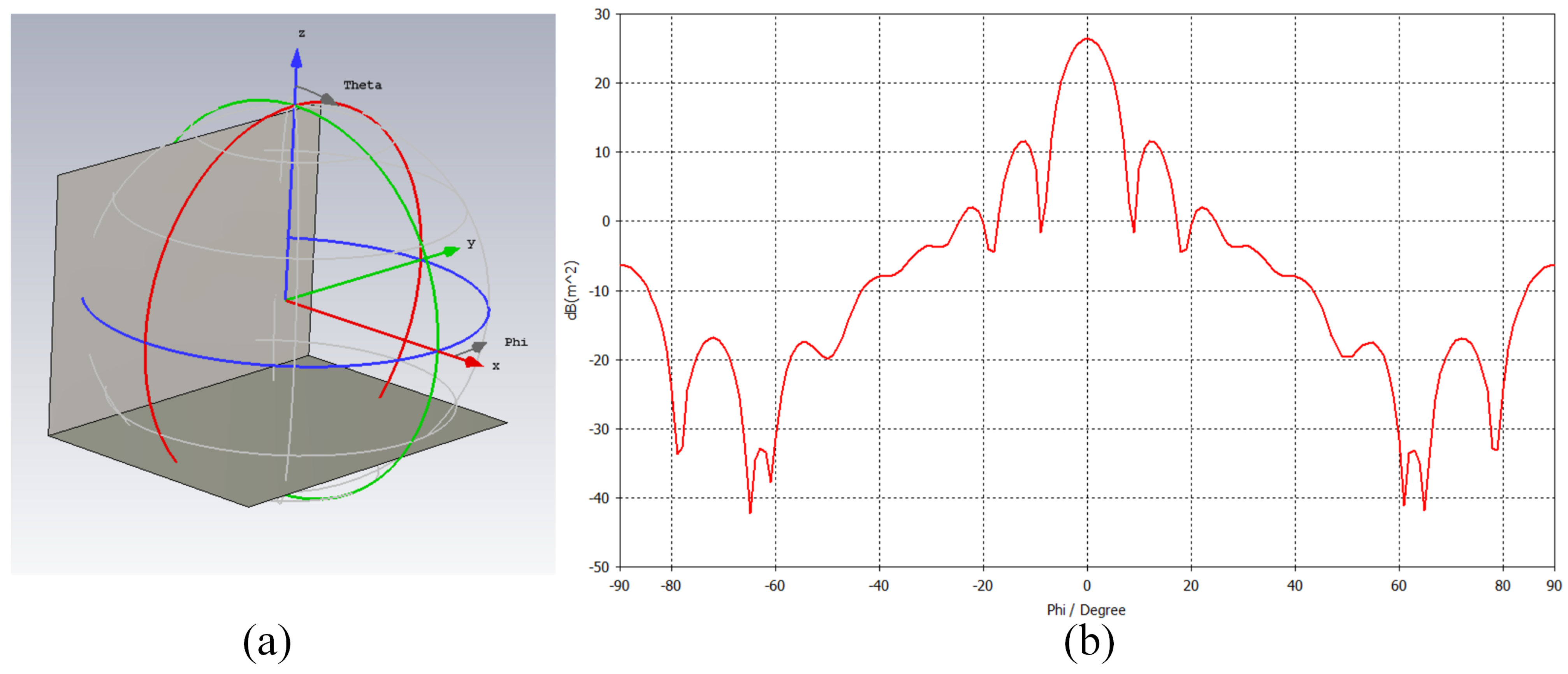
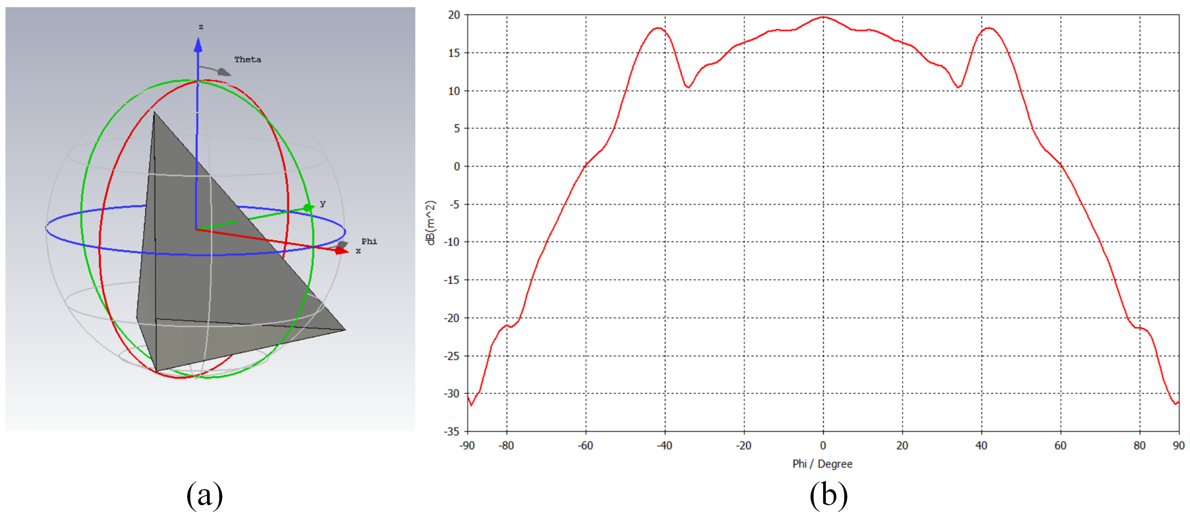
12]. The relationship between the dihedral and trihedral RCS with the polarization angle obtained by electromagnetic simulation software (CST) is shown in
Figure 1 and
Figure 2.
It can be seen from
Figure 1 that the RCS observed from the trihedral reflector remains almost invariant to variations in the polarization angle, and the 3 dB width of the beam is as high as 40°. From
Figure 2, for the dihedral reflector, the beam width is only 7°, which is greatly affected by the attitude deflection [
22]. The trihedral has better RCS stability, and its scattering matrix has rotation invariance, so it is generally believed that the trihedral scattering matrix remains stable under the condition of platform attitude deflection [
23]. Therefore, in this paper, the dihedral is mainly analyzed.
During the practical SAR imaging process, various uncontrollable factors cause changes in the platform’s attitude while moving along the track, particularly during airborne flights. Such changes are primarily caused by the airflow in the atmosphere. These attitude deflections mainly result in degrading the accuracy of the scattering matrix. To enable precise system calibration, it is essential to initiate compensation of the scattering matrix corresponding to the dihedral reflectors.
The attitude deflection of the platform during flight can be judged by the gyroscope integrated into the platform. In the three-dimensional coordinate system, the attitude deflection mainly consists of the yaw, pitch, and roll angles.
The geometric relationship between the track coordinate system
, the platform coordinate system
, and the target coordinate system
in the case of attitude deflection is shown in
Figure 3.
The yaw angle () is the projection of the longitudinal axis () of the platform on the horizontal plane and the projection of the track direction. Generally, north by east is positive.
The pitch angle () is the angle between the longitudinal axis of the platform and the horizontal plane. Generally, the upward direction is positive.
The roll angle () is the angle of the platform rotating around the longitudinal axis of the platform. Against the flight direction, the counterclockwise direction is positive.
In
Figure 3, the platform coordinate system
is obtained by rotating the track coordinate system
through the attitude angle. According to the definition of the platform attitude angle, the rotation order of several attitude angles is as follows: first, the yaw angle is rotated, and then the pitch angle is rotated. Finally, the roll angle is processed.
The classical calibration method [
23] in the case of airborne attitude deflection usually uses the equivalent POA to compensate for the calibration of the target attitude. The target under the influence of the attitude can be defined as:
where
D is the second-order rotation matrix formed by the equivalent POA angle
.
is the scattering matrix after the attitude angle compensation, and S is the scattering matrix without compensation.
This scheme performs well when the platform attitude angle is small. However, when dealing with large attitude angles, reducing the three-dimensional attitude angle to a one-dimensional POA can produce certain errors.
In order to achieve a more accurate calibration of the system polarization distortion, we propose an improved calculation method of the scattering matrix of the target in the case of platform attitude deflection.
The main error source of the POA method is that the change of the three-dimensional attitude angle is equivalent to one dimension through POA, ignoring the error of the attitude angle in other dimensions. In order to ensure the accuracy of the estimation of the scattering matrix of the corner reflector, this section attempts to derive the theoretical dihedral scattering matrix under the case of platform deflection through the theory of electromagnetic wave reflection.
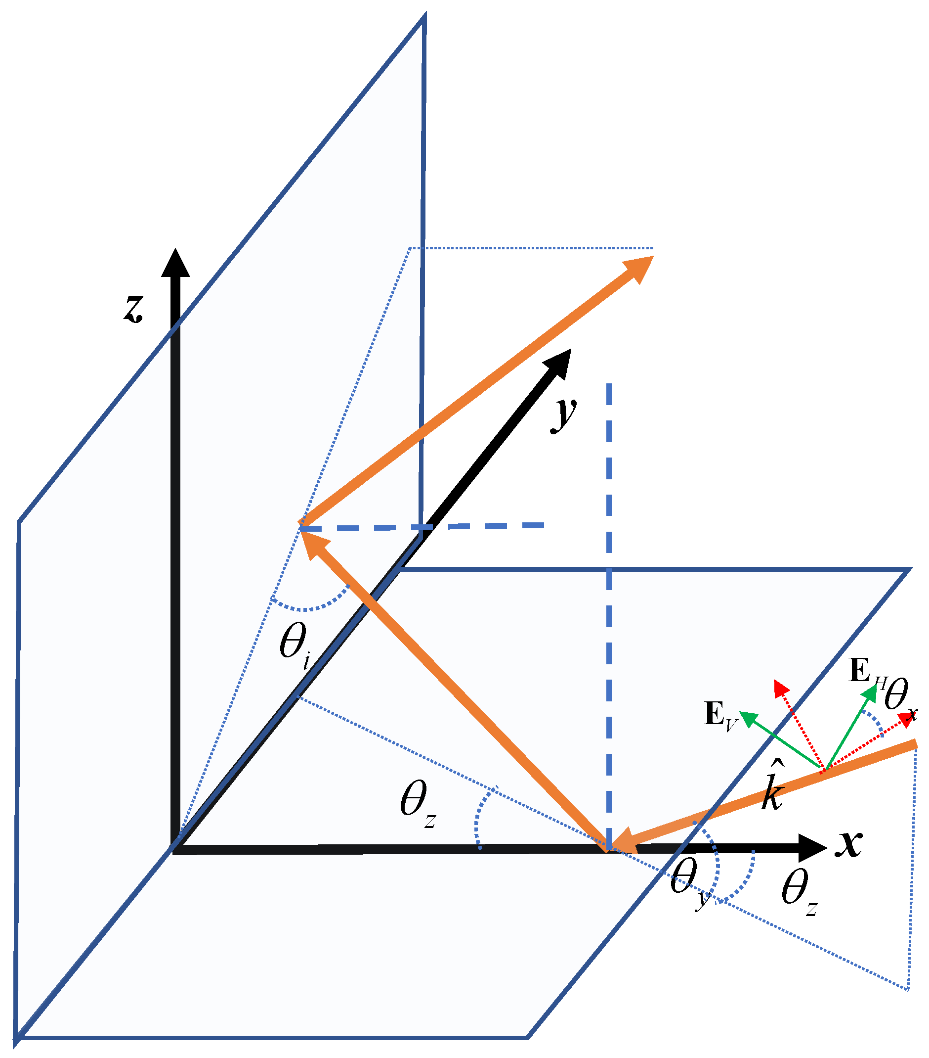
The schematic diagram of the interaction between the dihedral angle and electromagnetic wave is shown in
Figure 4. The
y-axis is established by the clamp line between the two vertical planes of the dihedral, and then the
x-axis and
z-axis are established on the two vertical planes of the dihedral (using the right-hand rule to form the target coordinate system). The orange solid line in
Figure 4 is a schematic diagram of the reflection of electromagnetic waves. Typical electromagnetic waves can be transmitted back to the radar receiver after two reflections on the dihedral reflector.
is the incident plane of the electromagnetic wave,
is the direction vector of the electromagnetic wave.
is the angle of rotation of the incident plane of the electromagnetic waves around the incident direction.
is the angle between the incident electromagnetic wave vector and the
plane, and
is the angle between the projection of the incident electromagnetic wave vector on the
plane and the
x-axis. It can be seen that the interaction between an incident electromagnetic wave and the dihedral can be completely determined by the definition of
,
, and
.
To simplify the calculation of the coordinates of the incident electromagnetic vector, the rotation matrix form is provided in Equation (
2) when a point target rotates around the coordinate axis in the three-dimensional coordinate system. It should be noted that if the coordinate system itself rotates around the coordinate axis, the rotation needs to be reversed.
where the subscripts
x,
y, and
z mark the coordinate axes of the rotation, and
represents the angle of rotation.
represents the rotation matrix of a point rotating around the
x-axis in a three-dimensional coordinate system;
represents the rotation matrix of a point rotating around the
y-axis in a three-dimensional coordinate system;
represents the rotation matrix of a point rotating around the
z-axis in a three-dimensional coordinate system.
According to the relationship between the incident electromagnetic wave vector and the target coordinate system shown in
Figure 4, the target coordinate system
rotates
around the
z-axis,
around the
y-axis, and finally
rotates around the
x-axis to obtain the electromagnetic wave incident coordinate system
. The process can be defined by the following equation. Considering that the coordinate system is rotated here, the rotation angle needs to be reversed.
Furthermore, we can obtain,
Let us bring the coordinates
,
of the horizontally polarized wave and the vertically polarized wave in the coordinate system
, respectively, to (
4). The coordinates of the horizontally polarized wave and vertically polarized wave components of the incident electromagnetic wave in the dihedral coordinate system
can be obtained.
At this time, the horizontally polarized electromagnetic wave and the vertically polarized electromagnetic wave can be decomposed into the propagation components of the
x-axis,
y-axis, and
z-axis in the dihedral coordinate system. According to the law of the electromagnetic wave reflection on the conductor surface, it can be seen that the reflected wave after reflecting on the
x–
y plane and
y-
z plane is represented as follows.
Finally, the corresponding scattering matrix can be obtained by solving the following formula.
Assuming
,
, at this time, the form of the scattering matrix of the dihedral under any
can be obtained as follows
Equation (
8) is consistent with the form of the scattering matrix of the rotation dihedral, which is also the scattering matrix of the dihedral under the influence of POA. Thus, the analysis based on the influence of the POA on the scattering matrix of the dihedral is only one dimension of the analysis in this section.
From the analysis of the interaction between the dihedral and the plane electromagnetic wave, it can be seen that as long as the values of , , and between the electromagnetic wave vector and the dihedral angle are determined, the theoretical dihedral scattering matrix can be obtained. Next, this section will analyze how to calculate the three included angles of the electromagnetic wave vector emitted by the radar in the dihedral coordinate system in the case of attitude deflection.
Let us define the direction vector of the electromagnetic wave emitted by the platform
. Its expression in the platform coordinates can be defined according to the radar incidence angle
.
Considering the geometric relationship between the direction vector of the electromagnetic wave and the direction vector of the horizontal and vertical magnetic fields, the direction vector defined by the horizontal and vertical polarized waves in the platform coordinates
can be further obtained as
The relationship between the platform coordinate
and the track coordinate system
can be defined by the rotation relationship based on the attitude angle: the track coordinate system
first rotates
around the
Z-axis, then rotates
around the
X-axis, and finally rotates
around the
Y-axis to obtain the platform coordinate system
.
Substituting the coordinate values in (
9) and (
10) into (
12), the expression of the electromagnetic wave direction vector and the horizontal and vertical electric field components in the track coordinate system can be obtained.
The geometric relationship between the three coordinate systems is shown in
Figure 3. Considering the side-view relationship between the target and the radar, for the layout of the standard 0° dihedral, the
y-axis of the target coordinate system and the
Y-axis of the track coordinate system are parallel. The conversion between the two coordinate systems can be conducted through the elevation angle. The platform coordinate system
rotated 90° around the
Z-axis, and then rotated
around the
Y-axis to obtain the target coordinate system
. Moreover,
is the elevation angle of the dihedral. The transformation relationship between the coordinate systems is obtained as follows.
If it is a rotation dihedral, in addition to the above rotation, a corresponding angle of rotation around the incident direction of the electromagnetic wave needs to be added.
According to (
13), the coordinates of the electromagnetic wave direction vector and the horizontal and vertical electric field components in the dihedral coordinate system can be obtained. After that, the calculation of the values of
,
, and
between the electromagnetic wave vector and the dihedral angle can be performed.
This method calculates
according to the angle between the projection of the electromagnetic wave direction vector
on the
x–
y plane and the
x-axis. We calculate
according to the angle between the electromagnetic wave direction vector
and the
x–
y plane. We solve the horizontal electric field direction vector
at
according to
and
, and solve
according to the angle between
and the real incident horizontal electric field direction
.
After obtaining
,
, and
, the corresponding scattering matrix can be obtained by solving (
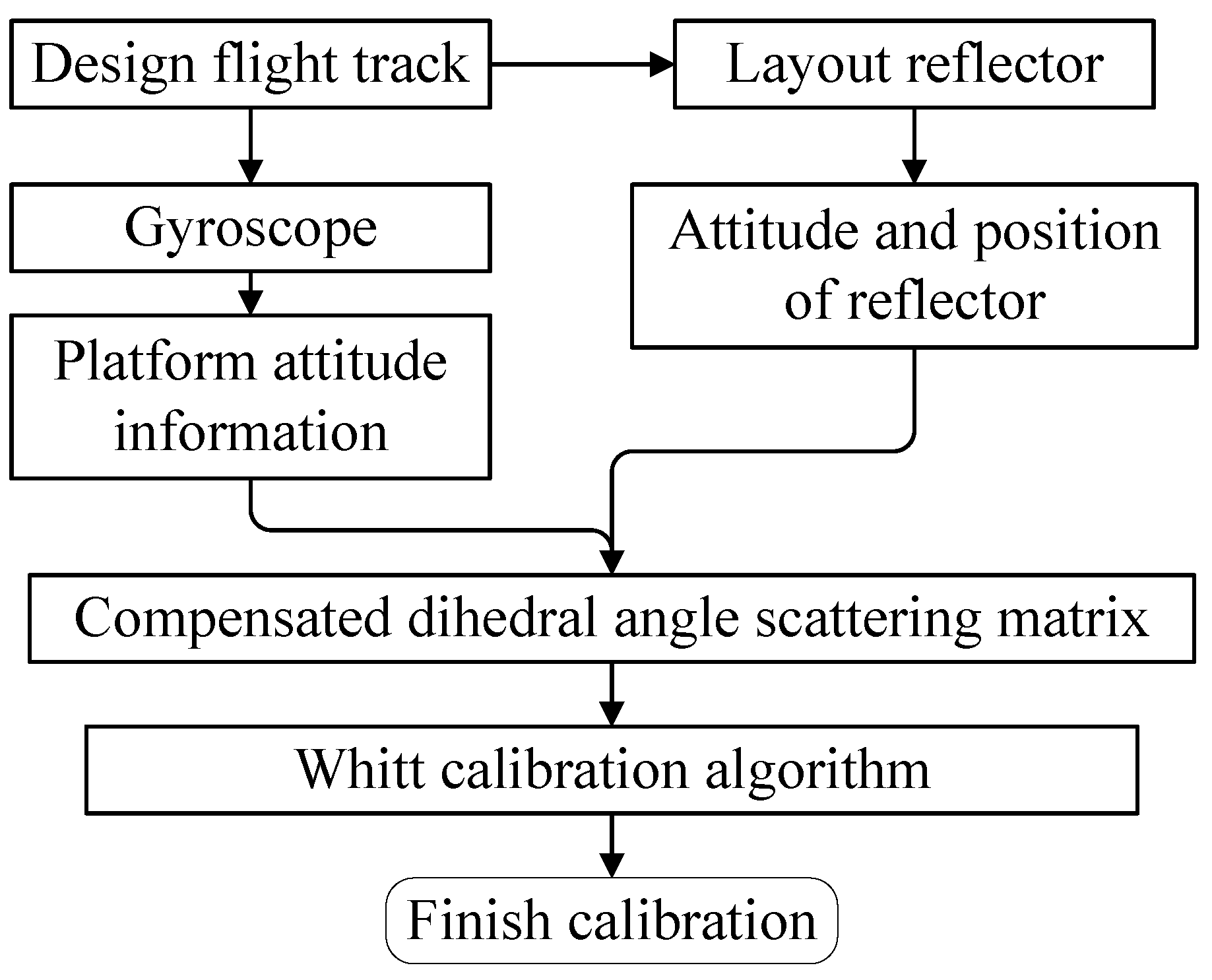
7). In this paper, the specific process of dihedral scattering matrix compensation and the calibration method of the system under platform attitude deflection is shown in
Figure 5.
First, we obtain the corresponding attitude angle and radar incidence angle according to the flight data. Afterward, the electromagnetic wave vector
and the electric field horizontal polarization vector are converted to the track coordinate system according to the attitude angle. Then, according to the type of the reflector, the coordinate system of the target is created, and the conversion relationship from the track coordinate system to the target coordinate system can be given according to the rotation relationship. At this time, the expressions of the electromagnetic wave direction vector
and the electric field horizontal polarization vector in the target coordinate system
can be obtained. According to (
14)–(
16),
,
, and
can be solved. Then, the calibrator’s scattering matrix is compensated. Finally, using the compensated scattering matrix and the Whitt calibration algorithm, the calibration of the system can be completed.
3. Results
The difference between the calibration method proposed in this paper and the POA method is mainly reflected in the update method of the dihedral scattering matrix. The scheme in this paper is a theoretical calculation scheme, and the POA scheme is an equivalent scheme. In this section, the difference in the scattering matrix obtained by the two schemes under different attitude angles is calculated to verify the error of the POA scheme.
In order to realize the characterization of the difference between scattering matrices, we first define the distance between two scattering matrices as follows:
where
and
are random polarized scattering matrices. In order to ensure the stability of the distance calculation, we normalize the scattering matrix according to the second norm of the scattering matrix.
According to the distance parameter of the scattering matrix defined in (
17), we can compare the difference between the dihedral polarization scattering matrix obtained by the scheme proposed in this paper and the POA scheme under different attitude angles.
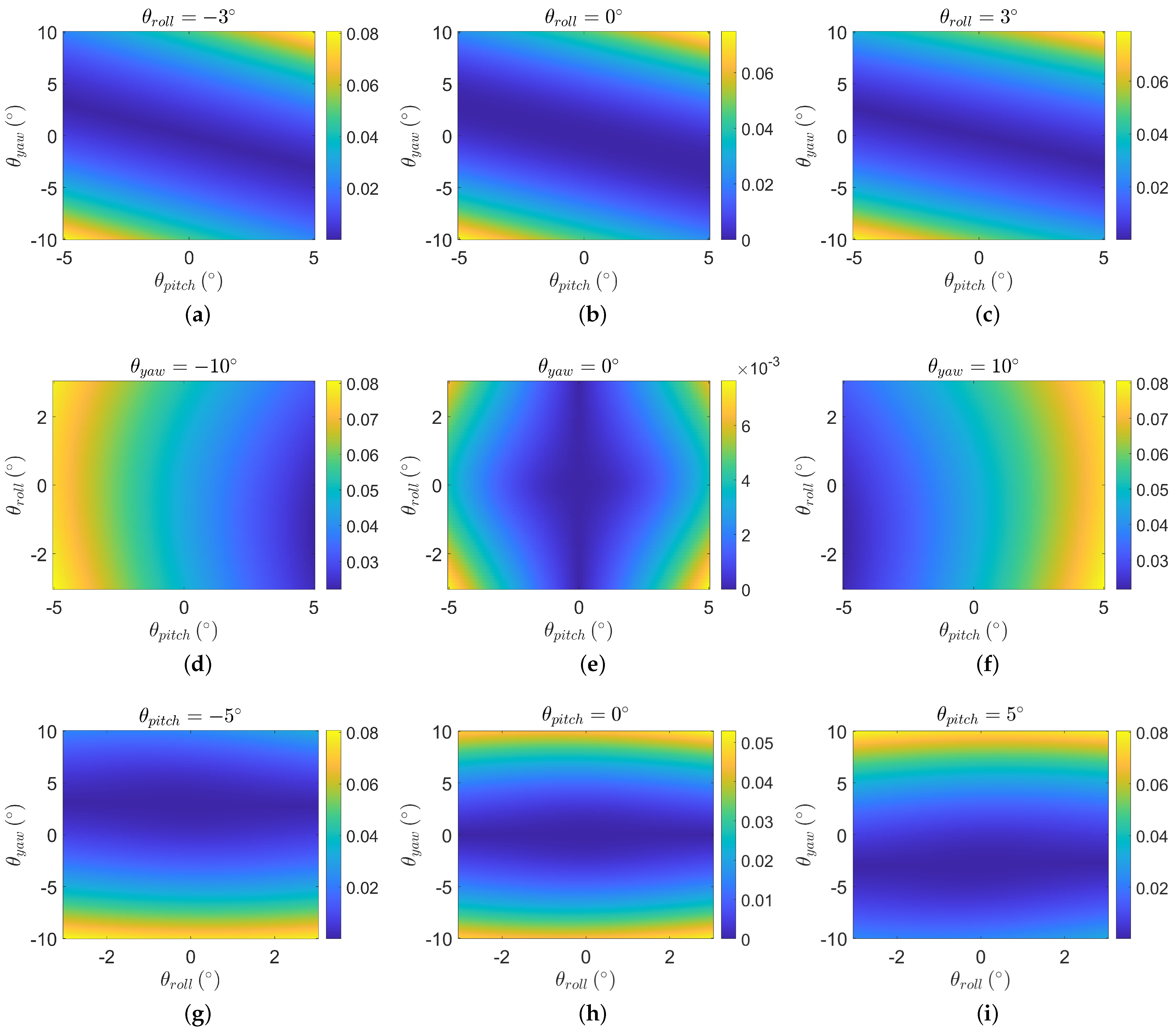
According to the size of the attitude deflection angle of a typical airborne platform, we set the simulation range as follows. The radar incidence angle
, the yaw angle
, the roll angle
, and the pitch angle
. First, we analyze the distance of the scattering matrix obtained from the two calculation methods under the condition of attitude deflection through the 0° dihedral. We calculate the distance between the scattering matrices obtained by the two methods within the above range; the results are shown in
Figure 6.
Figure 6 shows that, overall, when the attitude angle is small, the distance between the scattering matrices obtained by the two schemes is small. As the attitude angle increases, the distance between the scattering matrices also increases.
Figure 6a–c demonstrate the influence of the yaw angle and pitch angle on the distance between the scattering matrices when the roll angle is fixed. It can be observed that the three maps are largely similar. When the pitch angle is in the opposite direction to the yaw angle, the scheme proposed in this paper exhibits greater similarity to the result of the scattering matrix obtained through POA.
Figure 6d–f show the influence of the change of the pitch angle and roll angle on the distance between the scattering matrices when the yaw angle is fixed. It can be seen that in the case of 0° dihedral, the size of the roll angle has little effect on the difference between the scattering matrices of the two schemes. The influence is symmetrical regarding the position of
, and the influence increases with the increase of the roll angle modulus. At the same time, the yaw angle and the pitch angle restrict each other, resulting in the left–right symmetry in
Figure 6d,f due to the difference in the yaw angle.
Figure 6e shows that the existence of the yaw angle is the main reason for the difference between the scattering matrix obtained by the proposed scheme and the POA scheme. When the yaw angle is zero, the overall error is very small, but in the actual flight process, the yaw angle is also the main source of the attitude error.
Figure 6g–i show the influence of the change of the roll angle and yaw angle on the distance between the scattering matrices when the pitch angle is fixed. It can be seen that when the yaw angle is within ±2°, the error of the scattering matrix between the two schemes is small.
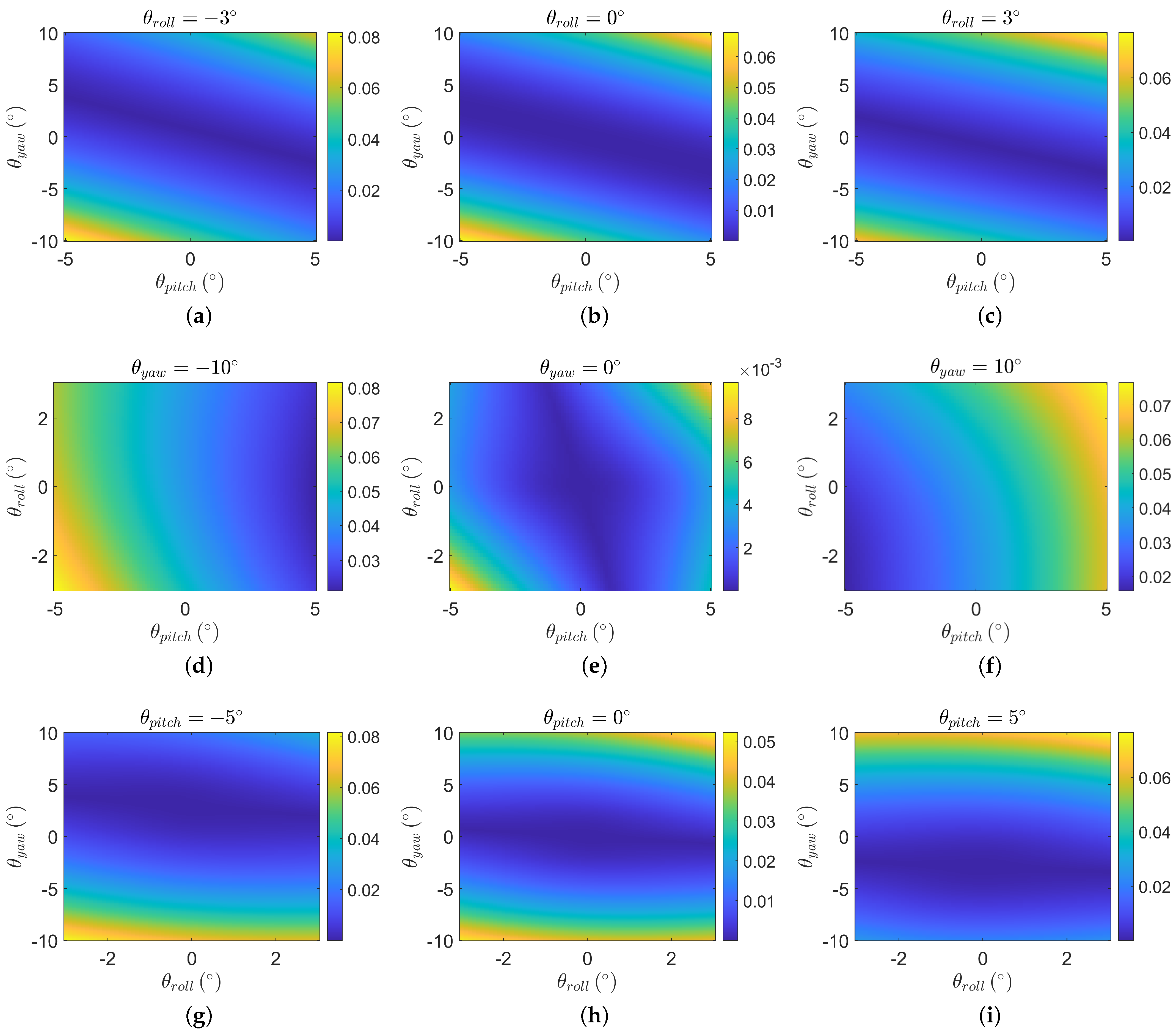
The distance between the scattering matrices obtained by the 22.5° dihedral angle under the two methods is further analyzed, as shown in
Figure 7.
It can be observed from
Figure 7 that compared to the 0° dihedral in
Figure 6, the results in
Figure 7 are approximately rotated by an angle. In this case, the influence of the roll angle on the distance between the scattering matrices becomes more pronounced. Additionally, the yaw angle and pitch angle continue to be the primary factors affecting the distance relationships between the scattering matrices estimated by the two methods, and they mutually affect each other. From
Figure 7e,g–i, it can be seen that the yaw angle remains the primary source of error between the two estimation methods, and a smaller yaw angle still ensures consistent estimation results from the two schemes.
It can be seen from the above simulation that unless the attitude angles are small, especially the yaw angle, the scattering matrix obtained by the POA-equivalent method is still different from the scattering matrix obtained based on the electromagnetic reflection theory proposed in this paper. This also shows that the one-dimensional equivalence of the POA method can not fully and accurately characterize the influence of the attitude deflection on the calibrators. In order to achieve a more accurate calibration effect of the polarization system based on the point target, the calibration method in this paper is more reliable in the presence of attitude deflection. Compared to the traditional method, this method does not need additional attitude information, and the calibration process is relatively fixed, which has good practicability.


