Abstract
Video Synthetic Aperture Radar (SAR) has shown great potential in moving target detection and tracking. At present, most of the existing detection methods focus on the intensity information of the moving target shadow. According to the mechanism of shadow formation, some shadows of moving targets present low contrast, and their boundaries are blurred. Additionally, some objects with low reflectivity show similar features with them. These cause the performance of these methods to degrade. To solve this problem, this paper proposes a new moving target shadow detection method, which consists of background modeling and shadow detection based on intensity information and neighborhood similarity (BIIANS). Firstly, in order to improve the efficiency of image sequence generation, a fast method based on the Back-projection imaging algorithm (f-BP) is proposed. Secondly, due to the low-rank characteristics of stationary objects and the sparsity characteristics of moving target shadows presented in the image sequence, this paper introduces the low-rank sparse decomposition (LRSD) method to perform background modeling for obtaining better background (static objects) and foreground (moving targets) images. Because the shadows of moving targets appear in the same position in the original and the corresponding foreground images, the similarity between them is high and independent of their intensity. Therefore, using the BIIANS method can obtain better shadow detection results. Real W-band data are used to verify the proposed method. The experimental results reveal that the proposed method performs better than the classical methods in suppressing false alarms, missing alarms, and improving integrity.
1. Introduction
Different from the conventional Synthetic Aperture Radar (SAR), the video SAR is a new technique that obtains sequential images and displays them like a movie [1,2,3]. With the capability of high-resolution imaging at a high frame rate, the video SAR can dynamically monitor the regions of interest. It was found useful in scene monitoring, coherent or noncoherent change detection, 3D imaging, and ground moving target detection and tracking [4,5,6,7,8].
Most of the traditional moving target detection methods focus on the Doppler shift and defocus energy characteristics [9,10,11]. However, the performance of these methods degrades in case of low-target Radar Cross Section(RCS). Besides, if the target moves too fast, its Doppler energy may shift out of the scene. On the contrary, if the target velocity is too small, its spectrum may drown in the clutter spectrum. Therefore, utilizing Doppler shfit and defocus energy to detect them is not robust. Fortunately, a moving target’s energy deviates from its true position and the incident energy of radar is also obstructed by the target, which creates a shadow in its position. It is independent of RCS and can be used as a reliable feature to find and locate moving targets. A detailed analysis of the shadow formation principle of moving targets was given in [12]. The features of moving target shadows, including intensity, size, and shape, are found useful for target detection and target recognition. In addition, it can be used for motion estimation and trajectory tracking due to appearing at approximately the real position. Therefore, shadow-based moving target detection and tracking have become a hot topic recently.
In recent years, many authors have carried out research on moving target shadow detection in video SAR [13,14,15,16,17,18,19,20,21,22,23,24,25,26,27,28]. The existing shadow detection methods are mainly classified into single-frame processing methods and multi-frame processing methods. Based on the single-frame imagery, Liu et al. used the signal-to-noise characteristics of different targets to distinguish moving targets from other targets [13]; since the optimal SCR threshold and the size of the moving target are unknown, this method is not robust. Considering the advantages of deep neural network technology in object detection and recognition, Ding et al. proposed a shadow detection framework based on deep neural networks [14]. In addition, Wen et al. also utilized the dual faster region-based convolutional neural network to detect moving target shadows [16]. In practice, the detection performance and generalization ability of these methods will degrade in case of a shortage of appropriate training data. Additionally, the intensity value of objects with weak reflectivity is low enough, which is similar to that of a moving target shadow. Nevertheless, the single-frame processing methods do not perform well in suppressing them, and usually require multiple frames to eliminate false alarms.
Therefore, the joint processing of multi-frame images can improve the performance of moving target detection. Tian et al. proposed the track-before-detect (TBD) algorithm to detect and track moving targets in the sequential images [18]. In addition, based on the dynamic programming-based track-before-detect (DP-TBD) algorithm, Qin et al. proposed a new method to detect and track high-maneuvering targets [19]. However, false tracks may appear when there are some areas with poor reflectivity. Furthermore, these methods usually assume that a target moves with constant velocity. When facing different motion states, the performance of these methods will degrade. Besides, Wang et al. proposed a classical multi-frame processing framework that includes image sequence registration, a median filtering method to extract background images, detect the constant false alarm rate (CFAR), and perform morphological filtering to eliminate false alarms [26]. Liao et al. proposed a shadow detection framework that models the background image through a single Gaussian model (SGM), and subtracts the background image and current image to obtain the binary result [28]. The performance of these methods is often related to the performance of background modeling. If the quality of the background modeling is poor, the detection performance will degrade. Another important point is that the features of moving target shadows are related to many factors, such as the speed of targets, the size of targets, and the imaging parameters [12]. Especially, the boundary of the moving target shadow will become blurred, and the contrast with the background will be induced. As a result, the contour of the detected target may be incomplete, and some targets cannot even be detected. Moreover, some low-intensity clutter produced by scattering changes and some objects with weak reflectivity may be misjudged.
These factors will reduce the accuracy of moving target localization, tracking, and motion parameters estimation. Therefore, it is necessary to further improve the accuracy and integrity of shadow detection results. We assume that the foreground and background images are well separated. Since the moving target’s shadow appears in the same position in the initial and the corresponding foreground images, there is a high similarity between them. As for other objects, there will be noise or some residual clutter in the corresponding position in the foreground image; as such, there is a low similarity between them. To the best of our knowledge, little attention has been paid to the neighborhood similarity of the moving target’s shadow in the literature. More importantly, the similarity is independent of the target’s intensity. Therefore, it can reduce missing detection, suppress false detection, and improve the integrity of detection results. Furthermore, the low intensity value of the moving target shadow is another reliable feature. Based on these, a new shadow detection method based on intensity information and neighborhood similarity of the moving target shadow is proposed in this article. Specifically, this new method consists of the following steps. Firstly, a fast method based on the BP algorithm is proposed to effectively reduce the time of image sequence generation. Secondly, this article gives the analysis of the low-rank property of static background and the sparse property of moving target shadow. Then, the low-rank sparse decomposition(LRSD) method is used to obtain background and foreground images. Thirdly, the intensity information and neighborhood similarity of the moving target’s shadow are used to realize target detection. Finally, the multi-frame information is used to eliminate some false points.
The main contributions of this article can be summarized as follows.
- 1.
- We propose a new moving target shadow detection method in video SAR, which firstly combines the neighborhood similarity and intensity information of the moving target shadow. The core of this method is that the shadow of the moving object has a high similarity between the original image and the corresponding foreground image. It performs better than the classical multi-frame detection methods in the integrity of detection results and false alarm suppression.
- 2.
- Background and foreground separation is the basis of the proposed shadow detection method. According to the SAR’s mechanism, the scattering variations of static objects are stable within a certain angle [29]. In addition, there is a high overlapping ratio between adjacent images in the image sequence. Therefore, the static objects can be considered low rank. Based on these, this paper introduces the LRSD technology to obtain cleaner background images and better foreground images.
- 3.
- We propose a method based on the BP algorithm to fast generate image sequence. In practice, there is a lot of data redundancy between overlapping image sequences. Taking advantage of the proposed method can effectively reduce redundancy calculation and improve the efficiency of image sequence generation.
The rest of this article is organized as follows. Section 2 will discuss the entire process of the proposed shadow detection method in detail. Section 3 presents the experimental results on real W-band data and gives the comparison with the classical shadow detection method. Section 4 discusses the results and further work. Section 5 draws the conclusion of this article.
2. Methodology
The proposed shadow-based moving target detection method is shown in Figure 1. The core of this method is the joint utilization of intensity information and neighborhood similarity of a moving target shadow. It consists of the following steps: fast image sequence generation, background image and foreground image separation, shadow detection based on intensity information and neighborhood similarity, and false alarm suppression. A detailed description of each part will be given in the next sections.
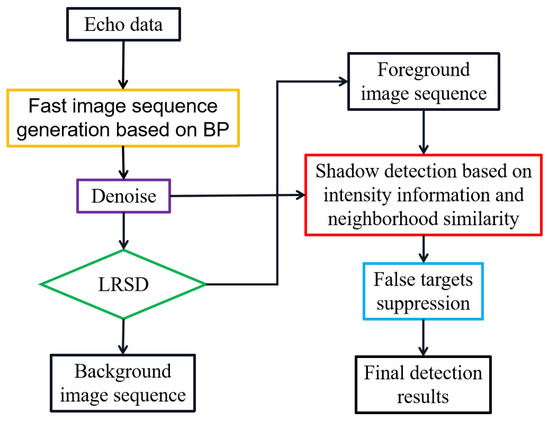
Figure 1.
Flow chart of the proposed moving target shadow detection method. Here, the LRSD and BP represent the low-rank and sparse decomposition and back-projection, respectively.
2.1. Fast Image Sequence Generation
Video SAR collects echo data by continuously illuminating the regions of interest. The return echo data are divided into N blocks with the appropriate window to form an image sequence using the suitable imaging algorithm. To better observe and monitor the objects of interest, it is common to generate overlapping image sequences, as shown in Figure 2. Compared with other imaging algorithms, such as Range Doppler algorithm (RDA) [30], Chirp Scaling algorithm (CS) [31], and Polar Format algorithm (PFA) [32], the Back-projection (BP) [33] imaging algorithm has the advantage of handling arbitrary flight trajectory and adopting incoherent pulses accumulation. As such, the BP algorithm is adopted to handle echo data. However, data repeated processing exists between overlapping image sequences, giving rise to slow image sequence generation. Therefore, it is necessary to reduce the processing of repeated data.

Figure 2.
Schematic diagram of generating overlapping image sequence.
As shown in Figure 2, for the given video SAR data, each echo data are used to form an image X, and the overlapping ratio is set to . The number of same echoes between adjacent frames is , . Correspondingly, the number of different echoes between adjacent frames is . We calculate the greatest common divisor M among , , and . M is the number of pulses contained in the smallest image unit I. Here, the BP imaging algorithm is used to generate image unit I.
where denotes an echo pulse and represents the BP imaging processing.
Consequently, the minimum number of image units contained in each frame and the number of image units between adjacent frames are and , respectively. The first frame can be obtained by the following formula:
Then, the frame can be obtained by the following equation:
Given the overlapping ratio and the number of pulses contained in each frame, the required image sequence can be quickly obtained by Equations (1)–(5). Due to the mechanism of SAR coherent imaging, there is inevitably some noise in the image. For the sake of reducing the interference of noise on target detection and recognition, the mean filtering method is employed to denoise.
2.2. Background and Foreground Separation
Video SAR usually continuously monitors the region of interest and can obtain the overlapping image sequence by the proposed f-BP method. According to the SAR’s mechanism, the scattering variations of static objects in a certain angle are isotropic. Therefore, there is a strong correlation between static objects in sequential images. As described in [34], Zhang et al. introduce the low-rank and sparse decomposition (LRSD) method to separate the static objects and the dofocusing energy of moving targets in circular SAR. However, the defocusing energy of the moving target does not appear at its real position and is offset out of the scene in video SAR. In contrast, its shadow appears at its real position and shows great potential in detecting a moving target. In addition, its shadow continuously moves in sequential images and shows darker features than the static objects. Therefore, this paper adopts the LRSD method to separate the background (static objects) and the foreground (moving target shadows), which can lay a good foundation for the subsequent shadow detection.
The LRSD method has shown good performance in optical video surveillance and other fields [35,36,37]. It mainly minimizes the following optimization problem to obtain the background and the foreground:
The matrix represents the input sequential images. Each frame image is stacked as a column vector by the , where and are the pixel numbers in different directions of . The -norm is the number of the nonzero element. The is used to control the tradeoff between the above items.
The sufficient low-rank property of the O is the basis of Equation (6). We use the empirical cumulative distribution function(CDF) of the singular matrix of O to verify these [38]. The metric of CDF is denoted as follows:
where is the singular value matrix of O, is the singular value, and denotes the top -percent of singular values.
It is a fact that the information contained in a matrix can be represented by its singular values [38]. In general, there is a strong correlation between each column of a rank-one matrix. The information contained in this matrix is less and is concentrated on its unique singular value. As for the full-rank matrix, the correlation between each column is weak, and its information is uniformly distributed on each singular value, as shown in Figure 3. From Figure 3, it can be seen that the CDF of video SAR data matrix is very close to the CDF of the rank-one matrix, and the top 10% singular values capture 80% information of O. It indicates there is a strong correlation between each column of O. Correspondingly, the matrix O has a sufficient low-rank property. Therefore, it is reasonable and appropriate to adopt the LRSD method to obtain the background and the foreground.
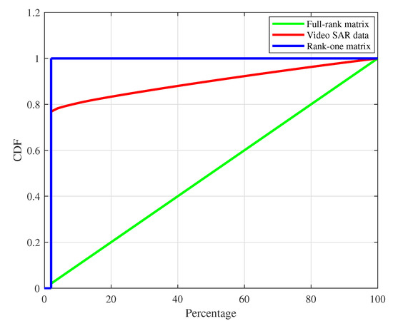
Figure 3.
Low-rank property analysis for video SAR data by using cumulative distribution function (CDF) to data matrix O.
Due to the nonconvexity of the and the -norm, the appropriate convex relaxation is adopted, where the -norm of B and the -norm of F are used as substitutes [39]. Then, Equation (6) can be rewritten as:
Equation (8) can be solved by minimizing the following Augmented Largrange Multiplier function:
where stands for a Largrange Multiplier matrix, , and is a positive scalar.
Since it is difficult to obtain the solution to or by directly minimizing Equation (10), an alternate approach of minimizing Equation (10) with respect to each component is adopted [40]. Based on the singular value thresholding algorithm [41], the closed solution to each component are given:
where denotes the singular decomposition, is the iteration step. is expressed for a scalar x as follows:
Finally, the low-rank static objects and sparse moving targets can be obtained by updating the above steps iteratively.
2.3. Multi-Scale Neighborhood Similarity for Shadow Detection
After obtaining the foreground image, the current methods mainly focus on utilizing the intensity-based detectors to process the foreground image and obtain the binarization result. However, the shadow features of moving targets are more complex than the defocused energy features of moving targets. The shadow features are not only associated with the size and the speed of moving targets, but also associated with the imaging parameters [12]. Within the subaperture, the time for the shadow area to be completely occluded is related to the velocity of the target. If the moving target moves too fast, there may not be a fully occluded shadow area, and the contrast between the shadow and the surrounding background will be weakened. If the speed of the moving target is moderate, there is a completely occluded area, and the shadow center area is darker under this condition. Notwithstanding, the phenomenon that the shadow edges are blurred exists. Therefore, only taking advantage of the intensity information to detect moving targets will give rise to incomplete shadow detection results and missing alarms. Additionally, it is technically difficult to distinguish objects with weak reflectivity from moving target shadows only relying on the low gray value feature of shadows; as such, these objects and some residual clutter produced by scattering changes may be misjudged.
To solve the above problems, we propose a new moving target shadow detection method combing the intensity information and neighborhood information, as shown in Figure 4. The gray value of the moving target shadow in the original image and foreground image is relatively low. Therefore, the original image and the corresponding foreground image are preliminarily processed by using intensity features.

Figure 4.
Flow chart of moving target shadow detection based on intensity information and neighborhood similarity.
Then, the preliminary detection results can be obtained by the following formula:
After the aforementioned low-rank sparse decomposition operation, there are only moving objects, noise, and some residual ground clutter in the separated foreground image. Because the moving target shadow appears at the same position in the initial image and the corresponding foreground image, there is a high similarity between them. However, the static objects in the original image correspond to noise or some residual ground clutter in the foreground image, as such, there is a low similarity between them. Based on the above analysis, the similarity of objects between the initial image and the foreground image can be considered a reliable and effective feature, which can be utilized to distinguish moving target shadow from other objects. Here, the similarity is defined as follows:
where and denote the initial image and the corresponding image, respectively and and represent the neighborhood of the piexl in the initial image and the foreground image.
According to Equation (20), it can be seen that the value of NS is independent of the intensity value of the pixel. Another important point is that the higher the similarity is, the closer the absolute value of the above formula is to 1. It should be emphasized that the NS value between noise and other static objects is low enough, even close to 0. Therefore, it is reliable to detect the moving target shadow by the neighborhood similarity.
Given the different sizes and speeds of moving objects, the corresponding shadows are different in size and shape. It is difficult to choose the optimal neighborhood size. If the neighborhood size is too small, there will be some discrete false alarms. On the contrary, some small shadows cannot be well detected. As a consequence, the multi-scale neighborhood similarity is adopted to ensure that there are as few discrete false alarm points as possible, and that the effect of object detection is as good as possible. The multi-scale neighborhood similarity is defined as follows:
where is the weighting factor and represents the neighborhood similarity calculated in different neighborhood sizes.
It should be emphasized that the number of neighborhood scales essentially depends on the imaging resolution and the size of the moving targets. Then, we can process the with the single global threshold to obtain detection results. The process can be written as follows:
Based on the intensity information and neighborhood similarity, we can obtain the final shadow detection results.
It should be noted that there are some false alarms caused by the shadows of static buildings in the above detection results, because the shadows of moving targets move continuously in the multi-frame images, while the stationary objects remain static or rotate to a certain extent. Consequently, the moving target shows a certain trajectory and covers a large number of pixel areas in the superposition of the multi-frame detection results. Nevertheless, the static objects cover a small fraction of pixels and exhibit irregular discrete trajectories. Therefore, the connected component detection method is applied to the superposition of the multi-frame detection results through appropriate thresholds. After that, the common parts between the resulted results and the corresponding R are the final shadow detection results.
3. Results
In this section, we utilize the proposed shadow detection method to handle the real W-band data. In addition, the experimental results of the classical detection method [26] are also given. The following experiments were conducted with the MATLAB R2018a software. The test platform is a computer with an Intel Core 3.2-GHz processor and 16 GB RAM.
3.1. Image Sequence Generation
Real W-band data are collected by the spotlight SAR sensor, which is attached to the unmanned aircraft and flies along a circular trajectory. The SAR sensor operates at 94 GHz with 900 MHz bandwidth. The flight height, flight radius, and flight velocity of aircraft are 500 m, 500 m, and 36 m/s. The azimuth beamwidth of SAR sensor is 6°, and the size of tested scene is 74 m × 74 m. Other parameters are shown in Table 1. The flight experiment was conducted by the Key Laboratory of Intellisense Technology, China Electronics Technology Group Corporation. The experiment scene is located in a roundabout road in Anyang, Henan province, China. These data contain numerous moving targets with different motion states.

Table 1.
Radar parameters for W-band video SAR data.
In order to monitor dynamic scenes and track targets effectively, airborne video SAR usually utilizes imaging algorithms to generate overlapping image sequences. However, there is a repetition calculation of data in the imaging process. To solve this problem, this paper proposes the f-BP method, as shown in Section 2.1. Next, the f-BP method and BP method are adopted to generate images. The length of subaperture is set to 1° and the overlapping ratio changes from 5% to 100% with an interval of 5%. These methods were used to obtain the image sequence. As shown in Figure 5, we calculate the average time to generate a single frame. It can be seen that the average time of each frame obtained by the BP method is almost the same under different overlapping ratios, resulting from the fact that each frame in the image sequence is formed by processing the same number of pulses. In contrast, with the overlapping ratio increasing, the average time of obtaining each frame using the proposed f-BP method gradually decreases. In particular, the average time is reduced by 1/2 at an overlapping ratio of 50%. More importantly, the average time is reduced to 1/4 at an overlapping ratio of 80%. These are mainly because the proposed method can reduce the repeated calculation of overfitting data. Furthermore, the higher the overlapping ratio is, the more obvious the improvement of the image sequence generation speed of the proposed method is. This is consistent with the principle of the proposed method. Therefore, the f-BP method is helpful and valuable for generating the image sequence in video SAR.
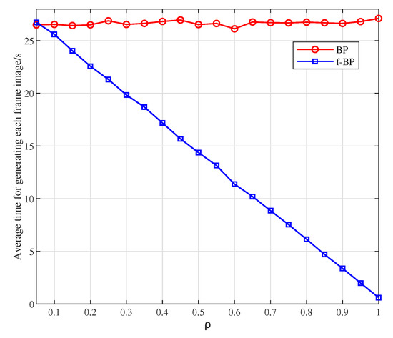
Figure 5.
Comparison of the time of each frame generated by the back-projection method (BP) and the fast back-projection method (f-BP) with different overlapping ratios.
3.2. Detection Results on Real W-Band Data
According to the SAR’s scattering mechanism [29], the scattering properties of objects can be considered isotropic at a certain angle. At this time, it is reasonable to assume that the static objects is low-rank. Here, we choose a 12.5° aspect angle to generate an image sequence of 50 frames using the f-BP method, where the length of the subaperture is 0.5°, and the overlapping ratio is . After that, the LRSD method is used to extract the background image and foreground image accurately. According to experiments, the is set to in the LRSD method, where and are the dimensions of the data matrix O. The positive scalar is set to and the iteration step is set to 2.2.
The formation mechanism of the moving target shadow shows that its intensity value is closely related to the speed and the size of targets and imaging parameters. Additionally, it is also affected by the reflectivity of surrounding clutter. Thereby, the intensity of the moving target shadow is not as distinct from the intensity of other objects as the intensity of the defocusing energy of moving objects. The 17th image, 17th foreground image, the inverse of 17th foreground image, and their corresponding intensity maps are given in Figure 6. It shows that the values of defocusing energy of moving targets are greatly higher than the pixel values of static objects, while the value of the moving target shadow is not significantly lower than the value of other objects. Therefore, the common intensity-based detectors and detection methods are not suitable for shadow detection.
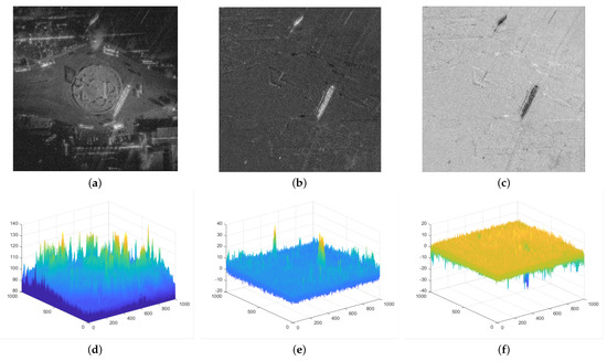
Figure 6.
Intensity analysis of a moving target shadow. (a–c) The 17th image, the 17th foreground image, and the inverse of the 17th foreground image, respectively, and (d–f) their corresponding intensity maps.
Then, we employ the proposed BIIANS method to process the foreground image sequence. The BIIANS method mainly takes advantage of the high similarity of the moving target shadow in the initial image and the corresponding foreground to distinguish them from other objects. Taking the 17th image as an example, we give the results of different steps of the proposed detection method, as shown in Figure 7. The moving targets are labeled by different colored boxes. For simplicity, this method is called LRSD-BIIANS. From Figure 7b,c, we can see that most of the static objects are retained in the background image, and the moving target’s shadow and its energy are extracted. We employ the method in Section 2 to process the foreground and initial image jointly. Since the pixel value of the moving target shadow is relatively low, the threshold and are used to preliminarily handle the initial image and the foreground image, which can reduce the interference of the moving target’s defocus energy and some residual clutter. According to experiments, the and are set to and , where and are the means of the initial image and the foreground and and represent the standard deviations of the initial image and the corresponding foreground.
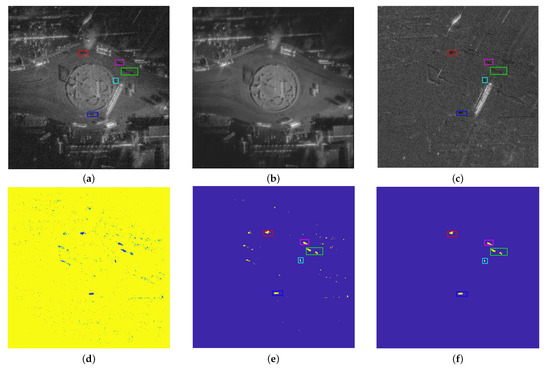
Figure 7.
Results of 17th image in different steps of the proposed moving target shadow detection framework. (a–c) The initial image, the corresponding background, and the foreground, respectively. (d) The multi-scale neighborhood similarity map. (e) The detection results of the BIIANS method. (f) The final detection reesults.
After the preliminary intensity judgment, the neighborhood similarity in different scales is calculated. Based on the imaging resolution and the sizes of moving targets, the neighborhood size ranges from to . In order to reduce the number of discrete false alarms and ensure the integrity of shadow detection results, the scale weighting operation is adopted. The weighting factors are set to 1, 1/2, 1/4, 1/2, and 1, respectively. The final similarity result is given in Figure 7d. The similarity of the moving target’s shadow is greatly higher than that of other residual clutter. Furthermore, the similarity of residual clutter is close to 0. This is consistent with the fact that the similarity between residual clutter or noise in the foreground image and the static objects in the initial image is very low. Then, the single threshold is applied to the similarity map to obtain the binarization detection result, where is set to 2.4. After that, the connected component detection is applied to the superposition of each 10- frame detection result through a suitable threshold. The final shadow detection result is the common part between the resulting result and each frame detection result, as shown in Figure 7f.
3.3. Performance Comparison on W-Band Data
After giving the experimental results of the LRSD-BIIANS method on W-band data, the classical method in [26] is chosen to deal with the W-band data. Besides, the CFAR detector is used to detect moving targets in the foreground image obtained by the LRSD method. For simplicity, this method is called the LRSD-CFAR method. The detection results and quantitative analysis of the LRSD-BIIANS method, the LRSD-CFAR method, and the method in [26] are given in this section.
3.3.1. Detection Results of Different Methods
The classical methods mainly utilize the fact that the intensity value of the moving target’s shadow is lower than other objects’ to realize detection. Firstly, the average intensity of pixels at the same position in every 10 frames is taken as the pixel intensity in the background image. Then, the CFAR detector is adopted to detect moving targets. The size of the CFAR window is , and the window is for the target test. The probability of the false alarm rate (pfa) is set to 0.005. In order to suppress false alarms in the detection result, the morphological operation and connected component detection are adopted. For simplicity, this method is called the MEAN-CFAR method. The detection results of different methods on the 18th frame are presented in Figure 8b–d The ground truth is presented in Figure 8a. Five moving targets are labeled by five color rectangle boxes, and the white rectangle boxes represent the false alarms in all detection results.
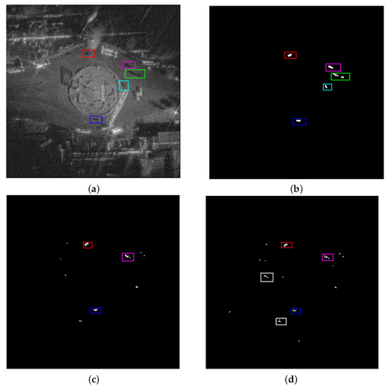
Figure 8.
Detection results of the 18th image using different methods. (a) Initial image. (b–d) LRSD-BIIANS method, LRSD-CFAR method, and MEAN-CFAR method, respectively. The five colored rectangles represent five ground moving targets. The white rectangles are the false targets.
Compared with the LRSD-BIIANS method, the MEAN-CFAR method and the LRSD-CFAR method mainly employ the lower gray value of the moving target shadow to realize detection. As shown in Figure 8d, only three moving targets are correctly detected, and there are also two false targets. Similarly, there are three true moving targets and two missed targets in Figure 8c. In addition, some false points appear in the detection results of LRSD-CFAR method and MEAN-CFAR method. This is mainly attributed to the following factors. On the one hand, according to the formation mechanism of moving target shadow, its intensity value is closely related not only to the motion state and the size of the moving target but also to the imaging parameters. If the target moves too fast, the time for fully occluded areas will shorten, causing the pixel value of its shadow to increase. Consequently, only utilizing the intensity information to realize detection can miss some true moving targets. On the other hand, the objects with low reflectivity present the same low gray feature. Furthermore, due to the anisotropic scattering nature of objects, some static objects in the initial image may become some dark regions in the foreground image, which will be misjudged to a certain extent.
In contrast, the LRSD-BIIANS method can detect five moving targets well, as shown in Figure 8b. Besides, no false targets and points appear in the results of the LRSD-BIIASN method. This is mainly attributed to the joint utilization of intensity and neighborhood information of moving target shadow in the foreground image and the initial image. Due to the anisotropic scattering characteristics of objects, some static objects present low gray values in the foreground image, while its intensity value of the same region in the initial image is generally not very low. Therefore, the joint intensity judgment in the initial image and the foreground image can eliminate these false alarms.
Another important point is that the detected targets of the LRSD-BIIANS method are in better agreement with the ground truth. On the contrary, the detected targets of the MEAN-CFAR method and LRSD-CFAR method miss some details and have incomplete contours, since the intensity of a moving target shadow is related to the occlusion time. Obviously, the occlusion time for the center area is longer than that of the edge. As a result, the central area of the shadow is darker than its edge. Therefore, the conventional intensity-based methods cannot detect them well and completely. There are three types of objects in the foreground image: shadows of moving objects, lots of noise, and less residual clutter. Obviously, regardless of noise or residual clutter, the similarity between them and the stationary objects at the same location in the original image is very low, even close to 0. On the contrary, the similarity of the moving target shadow between the initial image and the corresponding foreground is high, even close to 1. It is not affected by the intensity value of pixels according to Equation (20). Thereby, this method can effectively ensure the accuracy and integrity of shadow detection results.
For the sake of intuitively displaying the detection results of different methods, we randomly select four frames from the processed image sequence, and annotate the minimum circumscribed rectangles of the binarization results on the original image, as shown in Figure 9. The correctly detected shadow targets of the 3rd, 13th, 26th, and 38th frames using the LRSD-BIIANS method are labeled by pink rectangle boxes. The yellow and blue colored boxes are the correctly detected moving targets of MEAN-CFAR method and LRSD-CFAR method. The green circles represent the missing targets and the cyan boxes are the false targets.
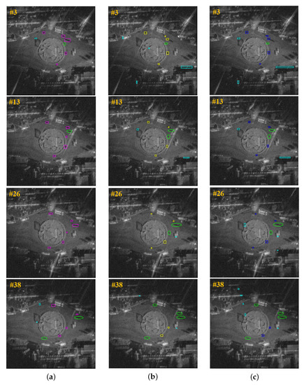
Figure 9.
Detection results of different frames by different methods. (a) Detection results on the 3rd, 13th, 26th, and 38th frames by the LRSD-BIIANS method, which are labeled by pink rectangles. (b) Detection results on the 3rd, 13th, 26th, and 38th frames by the LRSD-CFAR method, which are marked with yellow rectangles. (c) Detection results on the 3rd, 13th, 26th, and 38th frames by the MEAN-CFAR method, which are labeled by blue rectangles. The cyan rectangles represent false alarms and the green circles are missing targets.
From the detection results on the 3rd frame and 13th frame image by MEAN-CFAR and LRSD-CFAR methods, it can be seen that there are two false targets caused by the objects with low reflectivity. Nevertheless, the proposed LRSD-BIIANS method can effectively suppress them. Furthermore, the number of false targets of the LRSD-BIIANS method is significantly less than that of the MEAN-CAFR and LRSD-CFAR methods. This indicates that the proposed method outperforms in suppressing false alarms than other methods. Furthermore, only one moving target is not detected by the LRSD-BIIANS method in the 13th frame result. However, two moving targets are not detected by the MEAN-CFAR method and LRSD-CFAR method. In the 26th frame detection results, the result of the LRSD-BIIANS method contains six targets, while the results of the LRSD-CFAR and MEAN-CFAR methods contain only four targets. Similarly, in the 38th frame detection results, there are two missing targets in the result of the LRSD-BIIANS method, while the number of missing targets of the LRSD-CFAR method and MEAN-CFAR method are twice that of the LRSD-BIIANS method. This indicates that the proposed method contains more correct moving targets than other methods. Besides, it should be emphasized that the completeness of the shadow detection results plays a vital role in the accuracy of the moving target’s localization and velocity measurement. From Figure 9, we can see that the correctly detected moving targets by the LRSD-BIIANS method cover a larger area than those detected by the LRSD-CFAR and MEAN-CFAR methods. Due to the fact that the similarity is not affected by the intensity value of pixels according to (20), as such, the proposed method can effectively reduce the effect of blurred boundary and low shadow contrast. Finally, the corresponding detection results can lay a good foundation for subsequent moving target localization.
3.3.2. Quantitative Analysis
In this section, we quantitatively estimate the performance of different methods from three aspects: detection rate, false alarm rate, and detection integrity. Here, the , , and metrics are used for performance evaluation. The detail of these metrics are given as follows:
where is the total number of images in the image sequence, represents the number of images in which the number of correctly detected target shadows exceeds the given threshold, is the number of images in which the number of false targets exceeds the given threshold, and represents the number of images, where the number of overlapping pixels between the detected moving target and the corresponding ground truth surpasses the given threshold. Because it is very difficult to calculate the number of pixels contained in the ground truth, the maximum number of pixels contained in the detection results of all images obtained by all methods is used to replace that of the ground truth.
The curve and curve are shown in Figure 10 and Figure 11. The ground truth contains six moving targets. It is clear that all detection results of all methods contain two moving targets, as shown in Figure 10. Besides, all detection results of the LRSD-BIIANS method contain three moving targets. However, the detection probability of all frames is not guaranteed by the LRSD-CFAR and MEAN-CFAR methods. More importantly, the number of frames containing five moving targets obtained by the MEAN-CFAR and LRSD-CFAR methods does not exceed of the total frames. In contrast, the detection results of the LRSD-BIIANS method contain five targets. This indicates that the LRSD-BIIANS method performs better in detection probability. Another interesting is the results of red and yellow in Figure 10, which shows that the MEAN-CFAR method is slightly better than the LRSD-CFAR method in detection probability.
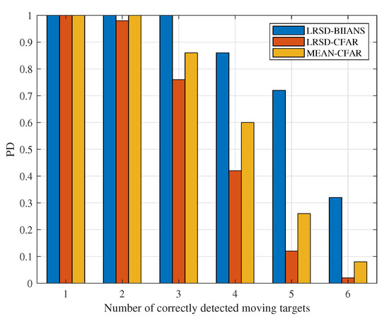
Figure 10.
Comparison of the detection capability of different methods.
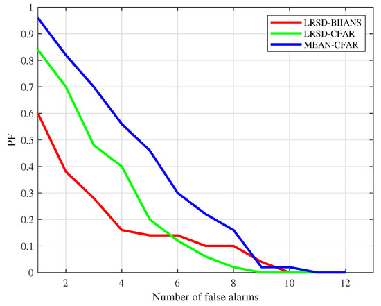
Figure 11.
Comparison of false alarms suppression of different methods.
Apart from the high detection rate, the proposed method also shows good performance in suppressing false alarms, as shown in Figure 11. When the number of false alarms is lower than six, the value of the LRSD-BIIANS method is significantly lower than that of the LRSD-CFAR and MEAN-CFAR methods. More specifically, when the number of false alarms is four, the value of the LRSD-BIIANS method is 16%, while the value of the LRSD-CFAR method and MEAN-CFAR method is twice and three times that of the LRSD-BIIANS method, respectively. This indicates that the detection results of the MEAN-CFAR method and LRSD-CFAR method contain more frames with four false targets, which will give rise to a severe troublesome in moving target localization. In addition, the PF value of the LRSD-CFAR method is smaller than that of the MEAN-CFAR method, indicating that the LRSD-CFAR method is superior to the MEAN-CFAR method in suppressing false alarms.
It should be emphasized that the integrity of the detection results affects the accuracy of moving target localization and tracking. According to the formation mechanism of the shadows of moving targets, some moving targets show low contrast with the surrounding background, and their boundaries are inevitably blurred, which is a great challenge for complete shadow detection. Therefore, it is necessary to evaluate the integrity of target detection results. We select two moving targets and give their curves of different methods, as shown in Figure 12. On the one hand, the value of the LRSD-BIIANS method is higher than that of the other two methods. It means that if the overlapping area between the detection result and the ground truth is the same, the LRSD-BIIANS method obtains more images with complete target shadow detection results than other methods. This can improve the accuracy of moving target tracking. Especially, as for target 1, when the overlap ratio is , the values of the MEAN-CFAR method and the LRSD-CFAR method are only and 24%, respectively.
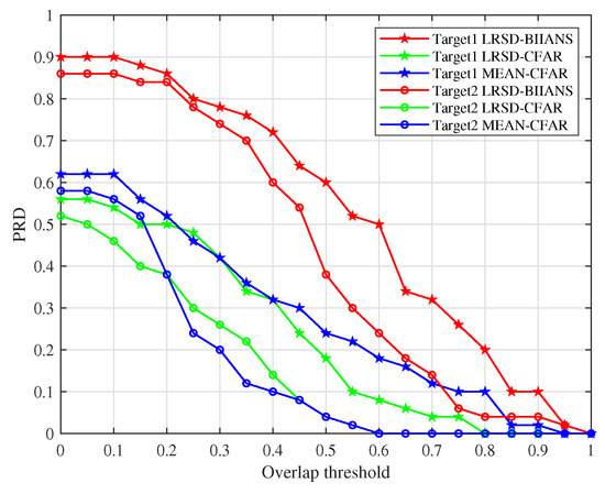
Figure 12.
Comparison of detection integrity of different methods.
Compared with those, the value of the LRSD-BIIANS method is 60%. On the other hand, the red curve descends more slowly than the blue curve and the green curve, indicating the overlapping area between the target correctly detected by the LRSD-BIIANS method and the ground truth is larger than that detected by other methods. Additionally, the value of the LRSD-CFAR method is close to that of the MEAN-CFAR method. This indicates that the LRSD-CFAR method has a similar performance as the MEAN-CFAR method in the integrity of shadow detection.
According to the quantitative evaluation and visual detection results on W-band video SAR data, the proposed LRSD-BIIANS method can obtain target shadow detection results with a low false alarm rate, high detection capability, and good integrity.
4. Discussion
The method proposed in this paper jointly utilizes the similarity and intensity information of a moving target shadow in the original and the corresponding foreground images to detect a moving target. The existing methods usually take advantage of the intensity information of a moving target shadow to realize detection. According to the formation mechanism of a target shadow, the intensity of the shadow of a moving target varies with its speed and size and the scattering characteristics of objects around it. As for moving targets with blurred boundaries and low contrast, the existing methods cannot detect them effectively, as shown in the experimental results. Additionally, the intensities of objects with weak reflectivity are low enough, and the existing methods may misjudge them as true moving targets.
Apart from the low intensity value of a moving target shadow, the similarity of a moving target shadow in the original and the corresponding foreground images is another important feature. As described in Equation (20), this is independent of the intensity value of a moving target shadow. Furthermore, the similarity of a moving target shadow is close to 1, while that of other objects is close to 0. Therefore, it can distinguish a moving target from other objects effectively. As shown in Figure 10, Figure 11 and Figure 12, the , , and curves indicate that the proposed method performs better in terms of detection capability and detection integrity.
However, when the shadows of moving targets are blocked by other objects, such as the defocusing energy of other moving targets, neither the proposed method nor the existing methods can find them. In addition, the shadows of moving targets with high speed are severely blurred, and the existing methods cannot detect them. Further work is needed to solve this problem by combining shadow features and defocusing features of moving targets.
We know that using an unmanned aircraft for data collection and analysis is very useful in a variety of practical applications [42], especially in moving target detection and tracking. However, when the recorded motion information of the unmanned flight platform is not accurate in practice, the stationary objects will be unfocused or blurred in the SAR image, which has a certain degree of negative effect on the shadow intensity of the moving target. We all know that the moving target’s energy deviates from its true position and the incident energy of radar is also obstructed by the target, which creates a shadow on its true position. Furthermore, the offset energy plays a more important role in the shadow formation of moving objects. If the motion errors is small, this effect is negligible compared to the offset energy of the moving target. As shown in Figure 7a, due to the motion errors of the unmanned flight platform, stationary objects in the resulted SAR image are slightly blurred. However, the shadows of the moving target are still very clear and the proposed method can detect them well. When the motion errors are large enough, the stationary objects will be severely blurred and the defocusing energy of other stationary objects will have a larger negative effect on the shadow of moving target. The contrast of a moving target shadow will be severely reduced. Worse still, the shadow of a moving target will be submerged in the defocusing energy of other objects. In theory, the existing detection methods cannot detect moving targets. According to the above, when the unmanned aircraft is equipped with high-performance GPU devices and processors, and accurate GPS recording facilities, the proposed method can be embedded into unmanned platforms and shows good performance on moving target detection.
5. Conclusions
This paper presents a new moving target shadow detection method in video SAR, which consists of f-BP, LRSD, and BIIANS. Firstly, the f-BP method is proposed for quickly generating the overlapping image sequence. Subsequently, on the basis of analyzing the low-rank characteristics of stationary objects and the sparsity characteristics of moving target shadows in the image sequence, the LRSD method is used to obtain a cleaner background and better foreground. Then, the BIIANS method jointly uses the low intensity information and high similarity of moving target shadows in the original image and the corresponding foreground image to realize moving target shadow detection.
Real W-band data are used to verify the proposed method. The experimental results reveal that when the overlapping ratio is 80%, the speed of each frame obtained by the f-BP method is three times faster than that obtained by the BP method. Furthermore, with the increase of the overlapping ratio, the speed of the f-BP method to generate each frame becomes faster. The visual detection results and quantitative evaluation of different methods on W-band data show that the proposed method can obtain target shadow detection results with a low false alarm rate, high detection capability, and good integrity. However, if the targets move too fast, their shadows will be severely blurred, and neither the proposed method nor the existing methods can find them. In addition, if the shadow of the moving target is blocked or partially blocked by the defocusing energy of another objects, the existing methods cannot detect them. To solve this problem, the joint utilization defocusing energy and shadow of moving targets to detect a moving target will be the topic of our future work.
Author Contributions
Conceptualization, Z.Z. and W.S.; methodology, Z.Z.; software, Z.Z.; validation, Z.Z., W.S., W.H. and Y.L.; formal analysis, Z.Z.; investigation, Z.Z.; resources, L.X. and S.S.; data curation, L.X. and S.S.; writing—original draft preparation, Z.Z.; writing—review and editing, W.S., Y.L. and W.H.; visualization, Z.Z.; supervision, W.S., Y.L. and W.H.; funding acquisition, W.S. and W.H. All authors have read and agreed to the published version of the manuscript.
Funding
This research was funded by the National Natural Science Foundation of China under Grant 61860206013, North China University of Technology Research start-up Funds 110051360002, the Fundamental Research Fund of Beijing Municipal Education Commission 110052972027/119, and the Program of Beijing Municipal Education Commission(KM202210009004).
Data Availability Statement
Not applicable.
Conflicts of Interest
The authors declare no conflict of interest.
References
- Balaji, B. A videoSAR mode for the x-band wideband experimental airborne radar. In Proceedings of the Algorithms for Synthetic Aperture Radar Imagery XVII, Orlando, FL, USA, 8–9 April 2010. [Google Scholar]
- Kim, S.H.; Fan, R.; Dominski, F. ViSAR: A 235 GHz radar for airborne applications. In Proceedings of the 2018 IEEE Radar Conference (RadarConf18), Oklahoma City, OK, USA, 23–27 April 2018; pp. 1549–1554. [Google Scholar]
- Palm, S.; Sommer, R.; Janssen, D.; Tessmann, A.; Stilla, U. Airborne Circular W-Band SAR for Multiple Aspect Urban Site Monitoring. IEEE Trans. Geosci. Remote Sens. 2019, 57, 6996–7016. [Google Scholar] [CrossRef]
- Damini, A.; Mantle, V.; Davidson, G. A new approach to coherent change detection in VideoSAR imagery using stack averaged coherence. In Proceedings of the Radar Conference (RADAR), Ottawa, ON, Canada, 29 April–3 May 2013. [Google Scholar]
- Liu, B.; Zhang, X.; Tang, K.; Liu, M.; Liu, L. Spaceborne Video-SAR moving target surveillance system. In Proceedings of the 2016 IEEE International Geoscience and Remote Sensing Symposium (IGARSS), Beijing, China, 10–15 July 2016; pp. 2348–2351. [Google Scholar]
- Jahangir, M. Moving target detection for synthetic aperture radar via shadow detection. In Proceedings of the 2007 IET International Conference on Radar Systems, Edinburgh, UK, 15–18 October 2007. [Google Scholar]
- Xu, H.; Yang, Z.; Chen, G.; Liao, G.; Tian, M. A Ground Moving Target Detection Approach Based on Shadow Feature With Multichannel High-Resolution Synthetic Aperture Radar. IEEE Geosci. Remote Sens. Lett. 2016, 13, 1572–1576. [Google Scholar] [CrossRef]
- Xu, H.; Yang, Z.; Tian, M.; Sun, Y.; Liao, G. An Extended Moving Target Detection Approach for High-Resolution Multichannel SAR-GMTI Systems Based on Enhanced Shadow-Aided Decision. IEEE Trans. Geosci. Remote Sens. 2018, 56, 715–729. [Google Scholar] [CrossRef]
- Cerutti-Maori, D.; Sikaneta, I. A Generalization of DPCA Processing for Multichannel SAR/GMTI Radars. IEEE Trans. Geosci. Remote Sens. 2013, 51, 560–572. [Google Scholar] [CrossRef]
- Budillon, A.; Schirinzi, G. Performance Evaluation of a GLRT Moving Target Detector for TerraSAR-X Along-Track Interferometric Data. IEEE Trans. Geosci. Remote Sens. 2015, 53, 3350–3360. [Google Scholar] [CrossRef]
- Raney, R.K. Synthetic Aperture Imaging Radar and Moving Targets. IEEE Trans. Aerosp. Electron. Syst. 1971, AES-7, 499–505. [Google Scholar] [CrossRef]
- Raynal, A.M.; Bickel, D.L.; Doerry, A.W. Stationary and Moving Target Shadow Characteristics in Synthetic Aperture Radar. In SPIE Defense + Security, Proceedings of the Radar Sensor Technology XVIII, Baltimore, MA, USA, 5–9 May 2014; SPIE: Baltimore, MD, USA, 2014. [Google Scholar]
- Liu, Z.; An, D.; Huang, X. Moving Target Shadow Detection and Global Background Reconstruction for VideoSAR Based on Single-Frame Imagery. IEEE Access 2019, 7, 42418–42425. [Google Scholar] [CrossRef]
- Ding, J.; Wen, L.; Zhong, C.; Loffeld, O. Video SAR Moving Target Indication Using Deep Neural Network. IEEE Trans. Geosci. Remote Sens. 2020, 58, 7194–7204. [Google Scholar] [CrossRef]
- Zhang, Y.; Yang, S.; Li, H.; Xu, Z. Shadow Tracking of Moving Target Based on CNN for Video SAR System. In Proceedings of the IGARSS 2018—2018 IEEE International Geoscience and Remote Sensing Symposium, Valencia, Spain, 22–27 July 2018; pp. 4399–4402. [Google Scholar]
- Wen, L.; Ding, J.; Loffeld, O. Video SAR Moving Target Detection Using Dual Faster R-CNN. IEEE J. Sel. Top. Appl. Earth Obs. Remote Sens. 2021, 14, 2984–2994. [Google Scholar] [CrossRef]
- Bao, J.; Zhang, X.; Zhang, T.; Xu, X. ShadowDeNet: A Moving Target Shadow Detection Network for Video SAR. Remote Sens. 2022, 14, 320. [Google Scholar] [CrossRef]
- Tian, X.; Liu, J.; Mallick, M.; Huang, K. Simultaneous Detection and Tracking of Moving-Target Shadows in ViSAR Imagery. IEEE Trans. Geosci. Remote Sens. 2021, 59, 1182–1199. [Google Scholar] [CrossRef]
- Qin, S.; Ding, J.; Wen, L.; Jiang, M. Joint Track-Before-Detect Algorithm for High-Maneuvering Target Indication in Video SAR. IEEE J. Sel. Top. Appl. Earth Obs. Remote Sens. 2021, 14, 8236–8248. [Google Scholar] [CrossRef]
- Luan, J.; Wen, L.; Ding, J. Multifeature Joint Detection of Moving Target in Video SAR. IEEE Geosci. Remote Sens. Lett. 2022, 19, 1–5. [Google Scholar] [CrossRef]
- Xu, X.; Zhang, X.; Zhang, T.; Yang, Z.; Shi, J.; Zhan, X. Shadow-Background-Noise 3D Spatial Decomposition Using Sparse Low-Rank Gaussian Properties for Video-SAR Moving Target Shadow Enhancement. IEEE Geosci. Remote Sens. Lett. 2022, 19, 1–5. [Google Scholar] [CrossRef]
- Wen, L.; Ding, J.; Cheng, Y.; Xu, Z. Dually Supervised Track-Before-Detect Processing of Multichannel Video SAR Data. IEEE Trans. Geosci. Remote Sens. 2022, 60, 1–13. [Google Scholar] [CrossRef]
- Yang, X.; Shi, J.; Chen, T.; Hu, Y.; Zhou, Y.; Zhang, X.; Wei, S.; Wu, J. Fast Multi-Shadow Tracking for Video-SAR Using Triplet Attention Mechanism. IEEE Trans. Geosci. Remote Sens. 2022, 60, 1–12. [Google Scholar] [CrossRef]
- Zhao, B.; Han, Y.; Wang, H.; Tang, L.; Liu, X.; Wang, T. Robust Shadow Tracking for Video SAR. IEEE Geosci. Remote Sens. Lett. 2021, 18, 821–825. [Google Scholar] [CrossRef]
- Zhong, C.; Ding, J.; Zhang, Y. Video SAR Moving Target Tracking Using Joint Kernelized Correlation Filter. IEEE J. Sel. Top. Appl. Earth Obs. Remote Sens. 2022, 15, 1481–1493. [Google Scholar] [CrossRef]
- Wang, H.; Chen, Z.; Zheng, S. Preliminary Research of Low-RCS Moving Target Detection Based on Ka-Band Video SAR. IEEE Geosci. Remote Sens. Lett. 2017, 14, 811–815. [Google Scholar] [CrossRef]
- Zhang, Y.; Zhu, D.; Xiang, Y.U.; Mao, X. Approach to Moving Targets Shadow Detection for Video SAR. J. Electron. Inf. Technol. 2017, 39, 2197–2202. [Google Scholar]
- Lei, L.; Zhu, D. An approach for detecting moving target in VideoSAR imagery sequence. In Proceedings of the 2016 CIE International Conference on Radar (RADAR), Guangzhou, China, 10–13 October 2016. [Google Scholar]
- Kaplan, L.M. Analysis of multiplicative speckle models for template-based SAR ATR. Aerosp. Electron. Syst. IEEE Trans. 2001, 37, 1424–1432. [Google Scholar] [CrossRef]
- Tan, X.; Li, J. Range-Doppler Imaging via Forward-Backward Sparse Bayesian Learning. IEEE Trans. Signal Process. 2010, 58, 2421–2425. [Google Scholar] [CrossRef]
- Runge, H.; Bamler, R. A Novel High Precision SAR Focussing Algorithm Based On Chirp Scaling. In Proceedings of the International Geoscience & Remote Sensing Symposium, Houston, TX, USA, 26–29 May 1992; pp. 372–375. [Google Scholar]
- Deming, R.; Best, M.; Farrell, S. Polar Format Algorithm for SAR Imaging with Matlab. In Spie Defense + Security, Proceedings of the Algorithms for Synthetic Aperture Radar Imagery XXI, Baltimore, MA, USA, 5–9 May 2014; SPIE: Baltimore, MD, USA, 2014. [Google Scholar]
- Desai, M.; Jenkins, W.K. Convolution backprojection image reconstruction for spotlight mode synthetic aperture radar. IEEE Trans. Image Process. A Publ. IEEE Signal Process. Soc. 1992, 1, 505–517. [Google Scholar] [CrossRef] [PubMed]
- Zhang, Z.; Shen, W.; Lin, Y.; Hong, W. Single-Channel Circular SAR Ground Moving Target Detection Based on LRSD and Adaptive Threshold Detector. IEEE Geosci. Remote Sens. Lett. 2022, 19, 1–5. [Google Scholar] [CrossRef]
- Wright, J.; Ganesh, A.; Rao, S.R.; Ma, Y. Robust Principal Component Analysis: Exact Recovery of Corrupted Low-Rank Matrices. In Proceedings of the Advances in Neural Information Processing Systems, Vancouver, BC, USA, 7–10 December 2009. [Google Scholar]
- Vaswani, N.; Chi, Y.; Bouwmans, T. Rethinking PCA for Modern Data Sets: Theory, Algorithms, and Applications. Proc. IEEE 2018, 106, 1274–1276. [Google Scholar] [CrossRef]
- Oreifej, O.; Li, X.; Shah, M. Simultaneous Video Stabilization and Moving Object Detection in Turbulence. IEEE Trans. Softw. Eng. 2013, 35, 450–462. [Google Scholar] [CrossRef]
- Pu, W.; Wu, J. OSRanP: A novel way for Radar Imaging Utilizing Joint Sparsity and Low-rankness. IEEE Trans. Comput. Imaging 2020, 6, 868–882. [Google Scholar] [CrossRef]
- Candès, E.J.; Li, X.; Ma, Y.; Wright, J. Robust Principal Component Analysis? J. ACM 2009, 58, 11:1–11:37. [Google Scholar] [CrossRef]
- Lin, Z.; Chen, M.; Ma, Y. The Augmented Lagrange Multiplier Method for Exact Recovery of Corrupted Low-Rank Matrices. arXiv 2010, arXiv:1009.5055. [Google Scholar]
- Cai, J.F.; Candès, E.; Shen, Z. A Singular Value Thresholding Algorithm for Matrix Completion. SIAM J. Optim. 2010, 20, 1956–1982. [Google Scholar] [CrossRef]
- Zhang, S.; Bogus, S.M.; Lippitt, C.D.; Kamat, V.; Lee, S. Implementing Remote-Sensing Methodologies for Construction Research: An Unoccupied Airborne System Perspective. J. Constr. Eng. Manag. 2022, 148, 03122005. [Google Scholar] [CrossRef]
Disclaimer/Publisher’s Note: The statements, opinions and data contained in all publications are solely those of the individual author(s) and contributor(s) and not of MDPI and/or the editor(s). MDPI and/or the editor(s) disclaim responsibility for any injury to people or property resulting from any ideas, methods, instructions or products referred to in the content. |
© 2023 by the authors. Licensee MDPI, Basel, Switzerland. This article is an open access article distributed under the terms and conditions of the Creative Commons Attribution (CC BY) license (https://creativecommons.org/licenses/by/4.0/).