1. Introduction
Crops are essential for sustaining human productivity and survival, balancing the carbon cycle of the earth, and providing the body with additional energy [
1]. It is helpful to measure the growth status of the crops in agricultural production to boost crop yields [
2]. Many research studies and experiments on utilizing GNSS signals to measure different variables, such as soil water content (SWC) [
3], sea surface height [
4], water depth [
5], and crop growth status [
6], have been conducted in recent years. The use of GNSS in location, navigation, timing, tropospheric water vapor, ionospheric delay, and scintillation applications has also been thoroughly and creatively documented by [
7]. Numerous variables have been identified as indices of crop growth status, including normalized difference vegetation index (NDVI) [
8,
9], enhanced vegetation index (EVI) [
10,
11], perpendicular vegetation index (PVI) [
12,
13], vegetation water content (VWC) [
14,
15], leaf area index (LAI) [
16,
17].
The Passive Reflectometry and Interferometric System (PARIS), developed by Martin Neira in 1993, takes advantage of the possibility to estimate ocean height [
18]. Later, while retrieving earth characteristics using GNSS-IR, researchers saw encouraging results. The direct signal will interfere with the reflected signal, which the GNSS receiver records as an oscillation in the signal-to-noise ratio (SNR). The SNR of the interference signal is related to SWC and crop growth state [
19]. Winter wheat was modeled as a multi-layer dielectric by Li et al., who gathered the SNR of interference signals utilizing a low-cost GNSS chip and a right-handed circular polarization (RHCP) antenna. Using the Lomb–Scargle periodogram (LSP) spectrum analysis, the height of the wheat canopy was determined. The root mean square error (RMSE) was 5.8 cm [
20]. Larson et al. connected the normalized microwave reflection index (NMRI) and VWC. Moreover, they provided a way to reduce the negative effects of precipitation and snow on NMRI. Based on this approach, more than 300 sites have been developed to retrieve VWC utilizing NMRI [
21].
The dielectric model of crops is difficult because of its anisotropy. Crop growth status may be determined by using the cross-polarization and dual-frequency characteristics of the GNSS signal. The ScoBi-Veg coherent bistatic vegetation model was introduced to improve the precision of existing vegetation scattering models. This model employed a Monte Carlo method to simulate the polarimetric reflectometry of vegetation-covered landscapes and took into account variations in the intensities and polarization states of the signal received along the beam path. The model may be used uniformly on a variety of platforms and altitudes [
22]. Egido et al. conducted long-term GNSS-R polarization experiments to investigate the impact of different terrestrial physical parameters on GNSS scattered signals. The results showed that the power of GNSS-reflected signals changed significantly under different SWC and crop growth statuses. They simultaneously examined the polarization characteristics of GNSS signals to mitigate the effect of soil roughness [
23]. Hugo et al. proposed the first dual-frequency multi-constellation GNSS-R polarimetric for boreal forests and lakes. The results suggest that different forest components are dispersed throughout the soil surface. To help with the modeling of forest models, they developed a vegetation simulator and generated scattering matrices for all of the trees that were formed [
24]. A method for retrieving the height of the vegetation canopy that makes use of the SNR dominant period was proposed. According to the results, the dominant period of the SNR undergoes significant changes, and SWC changes mostly affect the multipath signal phase. However, there is a greater possibility that changes in plant canopy height will alter the dominant period of the SNR [
25]. Chen et al. investigated the relationship between reflectivity and SWC [
26] to demonstrate the validity of a bilinear regression model using the variable reflectivity to produce SWC. The power attenuation that follows signal penetration can be used to retrieve the condition of vegetation growth. During an experiment, one of two identical GNSS antennas was positioned in the open sky and the other behind a walnut tree. The results show that VWC can be successfully recovered by power attenuation [
27]. RHCP and left-handed circular polarization (LHCP) GNSS antennas were placed at various locations beneath the plant canopy by Guerriero et al. while accounting for the anisotropy of the flora. They showed that the polarization characteristics of GNSS signals transmitting the vegetation canopy will change and that by using depolarization, tree parameters may be obtained [
28].
Occasionally, there are several frequency components for the vegetation-covered soil in the interference signals that GNSS receivers collect. Variational mode decomposition (VMD) was used by Ansar et al. to divide the raw time series into many intrinsic mode functions (IMFs) of different variables, which reduced the nonstationary quality of the time-series data [
19]. Dabbakuti et al. used an ionospheric total electron content model based on the singular spectrum analysis (SSA) to reconstruct the main changes and temporal distribution of the ionosphere at low latitudes [
29].
This study proposes an algorithm based on the empirical mode decomposition (EMD) to pre-decompose the reflected signals with different frequencies. The LSP is used to determine the spectrum and antenna height of each reflected signal for simultaneous retrieval of corn growth status (CGS) and SWC through a single GNSS antenna. The variances of the moduli between retrieved and actual antenna heights are used to separate the signals reflected by the soil surface and the corn canopy. Since the corn canopy is anisotropic, it reflects fewer coherent components of GNSS signals compared to the soil surface with less roughness. Consequently, when the corn height is low, the peak power of the LSP of the GNSS signal reflected by the soil surface is highest. Moreover, it gradually decreases with the increasing corn height. This study shows that there is a minimum variance in the modulus between the heights of the GNSS antenna measured by different satellites and its real height. Once the signals reflected by the soil surface and corn canopy are distinguished, the SWC and corn canopy height (CCH) can be determined by using GNSS-IR altimetry [
18] and semi-empirical SWC models. Additionally, the multi-GPS-satellite fusion method is used to improve the precision of retrieval and reduce the effects of anisotropy. The outline of this study is as follows.
Section 2 covers the theories and methods of different CGSs. The data processing is described in
Section 3 and experimental results are analyzed in
Section 4. The discussion and conclusions are presented in
Section 5 and
Section 6, respectively.
2. Theories and Methodologies
In addition to the line-of-sight signal, GNSS receivers also take up signals from other multipath sources [
30]. The amplitude, frequency, and phase of the reflected GNSS signal, however, are related to the SWC and the CGS. In the vegetation remote sensing model, the leaf is always seen as an elliptical disk dielectric while the corn canopy is seen as a planar dielectric. Both the CCH of the corn canopy and the VWC of the corn leaf serve as representations of the CGS. The GNSS-IR altimeter and electromagnetic wave attenuation can then be used to determine the CCH and leaf VWC, respectively.
As shown in
Figure 1, the geometry of GNSS signals includes those delivered down from the line-of-sight, those reflected by the soil surface, and those blocked by corn leaves. As seen in the left portion of the figure, the GNSS antenna can take up signals that are simultaneously reflected by the soil surface and corn canopy, which can interfere with the direct signal. Using GNSS-IR altimetry and semi-empirical SWC models, we can obtain CCH and SWC in this case. The corn leaf will block the GNSS signal if the corn is taller than the antenna, as shown in the right portion of the figure. The enlarged portion of the figure illustrates how GNSS signals transmit through a corn leaf. The thinness of the corn leaf means that changes in the satellite’s elevation angle have a minimal effect on the distance that a signal transmits through it. This will be demonstrated in a later simulation. In this case, the power attenuation of the GNSS signal can be used to obtain the VWC of the corn leaf.
is the satellite elevation angle and
is the angle formed by the refracted electromagnetic wave and the horizontal plane, as seen in
Figure 1. Given that the corn canopy comprises air and that the refraction is not evident, we ignore the difference and assume that
.
According to electromagnetic wave propagation theory, the signal detected by a GNSS receiver with one antenna is a superposition of direct and reflected signals. As the frequencies of the direct and reflected signals are essentially comparable and the propagation path is different in the ground-based situation, the transmissions will display an interference phenomenon, which will cause the interference signal to oscillate [
31]. A geodetic GNSS receiver records this interferometric signal as the SNR, and the mathematical model is indicated by [
32]:
where
represents the amplitude of the direct signal,
and
represent the amplitude of reflected signals from the soil surface and corn canopy, respectively.
and
represent the phase difference between the direct and reflected signals, respectively.
This section will focus on theoretical research related to the separation of reflected signals from the soil surface and corn canopy.
2.1. Separate Reflected Signals from Soil Surface and Corn Canopy
To retrieve SWC and CGS simultaneously, it is necessary to separate the two reflected signals first, according to Equation (
1). Using GNSS-IR remote sensing, reflected signals with different frequency components may be found. The initial step should be to separate the signals from distinct frequency components. The EMD method was developed by Huang et al. and can separate different frequency components of complex signals [
33].
We focus on how to separate reflected signals of different frequencies and then determine which frequency of the reflected signal is the soil surface reflection and which frequency is the corn canopy’s reflection. In addition to frequency, the signals reflected by soil and corn differ in the following aspects: (i) there are more coherent components in the reflected signal from the soil surface; it has a higher peak power in the LSP spectrum than the signal reflected by the corn canopy. (ii) The moduli between the actual GNSS antenna heights and the ones calculated using the reflected signal from the soil surface by different satellites show the least variance.
The occlusion caused by the corn canopy will reduce the strength of the signal reflected by the soil, resulting in mistakes in signal discrimination. The primary criterion used by this model to make decisions is the variance in the moduli between the retrieved and actual antenna heights. The separation method suggested in this study is explained as follows:
- 1.
Preliminary selection of the IMF:
- (a)
EMD is used to extract the high-frequency components and then the low-frequency components. As high-frequency components mainly consist of environmental noise, the LSP spectrum of the last five IMFs (lower frequency) and the mean values of the peak power of different LSP spectra were calculated.
- (b)
After running an LSP estimation on the five IMFs, the two IMFs with the best isolated-peak characteristics should be selected.
- 2.
Normalized LSP peak power:
- (a)
The top n largest values of the LSP peak power and the corresponding frequencies from different satellites and IMF were calculated, respectively, for one IMF, where i represents the PRN of each satellite and j represents the serial number from 1 to n. Considering that low LSP peak power may be caused by noise, and to reduce the calculation times, we calculated the value of n by .
- (b)
We use the SNR of the interferometric signal from one satellite and normalize the LSP peak power
of the two IMFs as follows:
where
represents the max of
.
- 3.
We calculate the variance of the same interval for different satellites:
- (a)
We determine the peak power interval: 0–1 was divided into n equal parts; each interval has a length of . We put and into the corresponding interval.
- (b)
We calculate the vertical distance between the reflector (soil surface or corn canopy) and the antenna phase center (antenna height):
where
represents the wavelength of the electromagnetic wave.
- (c)
We calculate the variance of in the same interval measured by different satellites. The IMF reflected by the soil surface has the smallest variance, whereas the IMF (the other one) reflected by the corn canopy has the second-smallest variance.
It is important to keep in mind that it will be difficult to have any IMFs reflected by the corn canopy if the corn is higher than the GNSS antenna.
2.2. The Retrieval of SWC
Theoretical, semi-empirical, and empirical models are commonly used to estimate the soil dielectric constant for the purpose of retrieving SWC. A semi-empirical model is commonly used for GNSS-IR-based SWC retrieval. This model involves the incorporation of empirical parameters to match observed data with a theoretical model. In addition to the Topp model [
34], Wang model [
35], Dobson model [
36], and universal refractive index-mixed dielectric model [
37], several other conventional semi-empirical models of the soil dielectric constant are also available. Polder and Van Santan [
38] also proposed the basic framework for the dielectric mixing model; DeLoor provided a model suitable for determining the dielectric constants of mixtures [
39]. As the empirical representation of the soil dielectric constant is often produced by simply fitting the observed data without using any theoretical rationale, building the model is relatively straightforward.
The relationship between reflectivity and the soil dielectric constant is specific, and the SWC is the main factor affecting the dielectric constant. We can extract the direct signal and calculate the amplitude ratio of the direct and reflected signals after distinguishing the signal using the method above. Afterward, a semi-empirical model was used to determine the soil’s dielectric constant. An improved empirical relationship between relative permittivity and SWC is reported in [
34]. Time domain reflectometry (TDR) is commonly used to measure the soil dielectric constant. Topp studied the effects of soil water content, frequency, and soil texture on soil dielectric properties. The cubic equations for the soil dielectric constant
at different water contents were discovered via data fitting.
where
represents the soil volume water content.
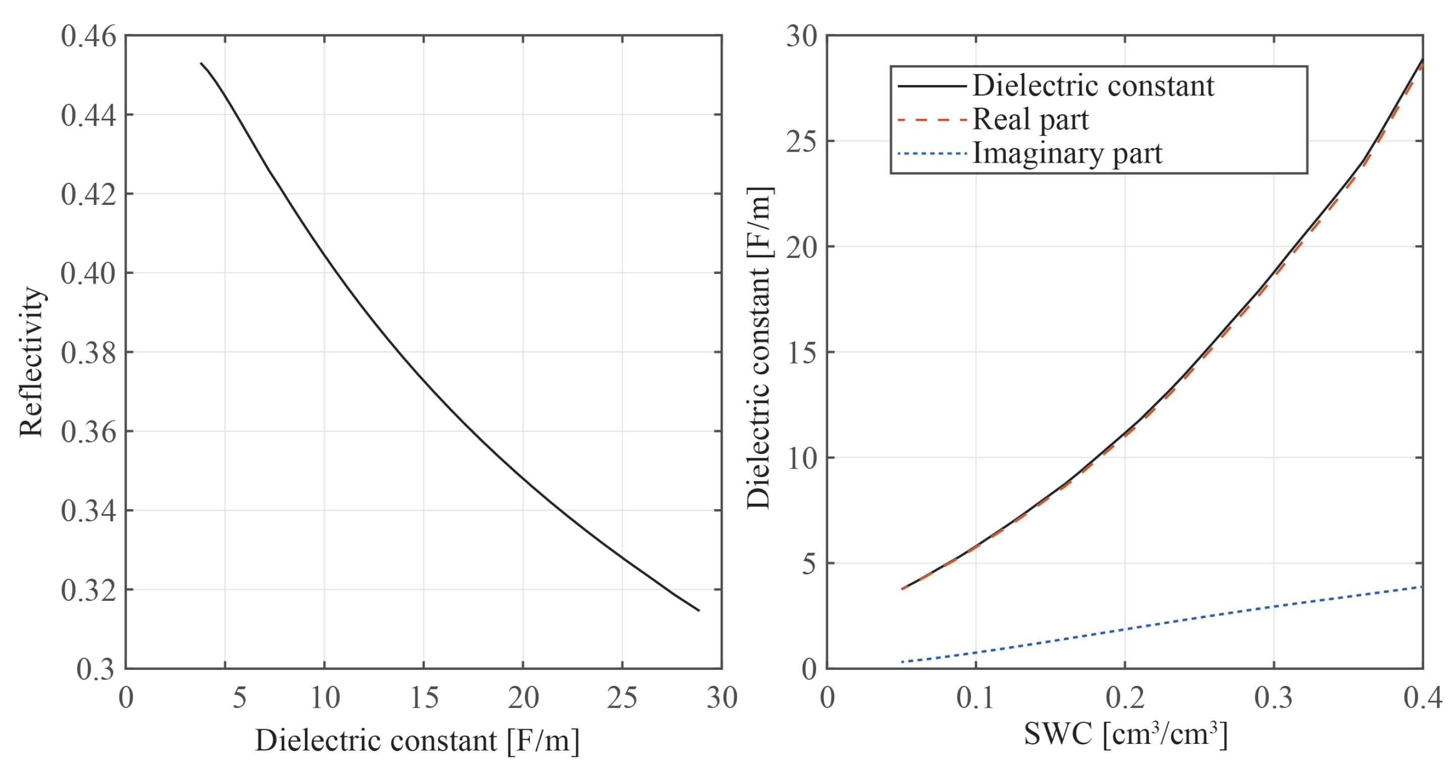
To simplify the computation of SWC retrieval, we simulated the relationship between the amplitude ratio (reflectivity) of the direct and reflected signals and the soil’s dielectric constant. The results are shown in
Figure 2. The x-lab of the left panel is the soil dielectric constant, whereas the y-lab of the right panel is the SWC, and the x-lab of the left panel is the reflectivity. The figure shows that when SWC rises, the soil dielectric constant rises while the reflectivity
of the RHCP component falls. Additionally, there is a nearly linear connection between reflectivity and the soil dielectric constant. Thus, using Equation (
5), we may create an approximation connection.
where subscript
represents that both the transmitted and reflected signals are RHCP.
a and
b represent the fitting coefficients, respectively.
Equations (
4) and (
5) together with the low-order linear fitting method may be used to construct a semi-empirical model of the relationship between the reflectivity and SWC. Moreover, the link between reflectivity and SWC may be obtained by converting Equation (
5), which has two unknowns (
a and
b), into Equation (
4);
a and
b may be derived using the same SWC and the reflectivity of the experimental location. Lastly, in the experimental site, SWC retrieval can be done at different times.
The effect of soil roughness was not considered in the model presented in this study because the influence of corn on SWC retrieval is much greater than that of soil roughness. The empirical relationship of Equation (
5) will also be affected by soil roughness, which can partially alleviate its impact.
2.3. Corn Lower than GNSS Antenna
The left part of the antenna in
Figure 1 depicts the geometric connection of the GNSS signal propagation when corn is lower than the GNSS antenna. According to
Figure 1, the path delay
of the direct and reflected signals is the modulus of two red lines and can be described as [
32]:
where
represents the vertical distance between the GNSS receiver antenna and the corn canopy, and
represents the elevation angle of the satellite.
The oscillation frequency
of the interference signal can be calculated by the following formula, which is a function of the sine of the elevation angle [
32]:
where
represents the wavelength of the GNSS electromagnetic wave. We assume that the
has no change in the growth period of corn in one day [
21].
Equation
7 calculates the frequency of the oscillating signal to retrieve the height of the corn canopy. In signal processing, LSP is frequently used to calculate the GNSS multi-path signal’s frequency. After Lomb revised the Schuster spectrum estimation in 1976, taking into account the generalized form of the periodogram, Scargle created the LSP spectrum analysis technique in 1982. The spectrum
of the raw signal
can be calculated as [
40]:
where
represents the integrating time; to guarantee the time-shift invariance, each time-delay
can be described as:
Using the technique in
Section 2.1, we separate the GNSS signals reflected off the soil surface. The CCH can be determined by
where
H represents the antenna’s actual height and
represents the retrieved height in a sub-small variance interval.
2.4. Corn Higher than GNSS Antenna
The GNSS antenna has difficulty receiving signals reflected by the corn canopy when the corn is taller than the antenna. The right side of
Figure 1 shows the path of propagation of the GNSS signal transmitted by the corn leaves. A corn leaf is an incredibly thin elliptic disk dielectric that has the capacity to weaken electromagnetic power. The primary objective of this part is to establish the relationship between signal power attenuation and the VWC of the corn leaf.
In this study, a mathematical model was established first. Assuming that the power of the GNSS signal that irradiates into the leaf is
, the power attenuation when the transmission distance
in the leaf is
and can be described as [
41]:
where
is the attenuation factor:
where
and
represent the real and imaginary parts of the corn leaf permittivity, respectively.
represents the permeability in vacuum, and
F/m represents the permittivity in vacuum.
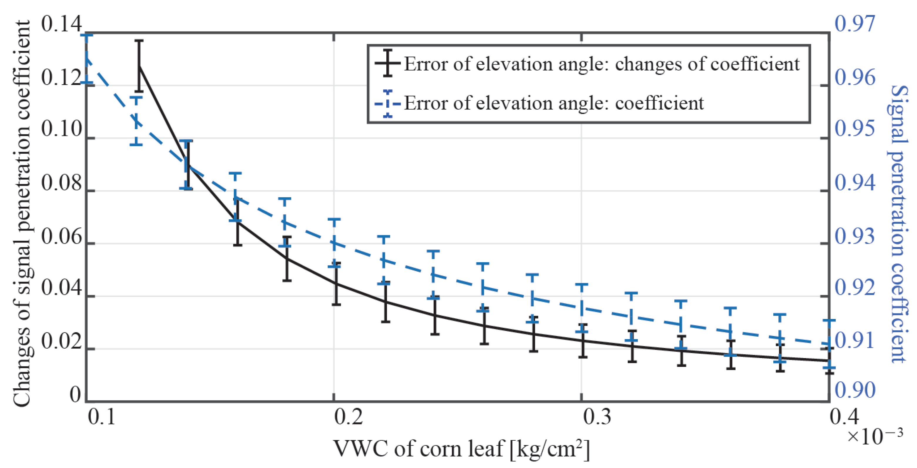
Due to the thinness of the corn leaf, the VWC, which regulates the degree of the signal power attenuation, has a significant effect on the dielectric constant. To determine the effects of the satellite elevation angle and the corn leaf’s VWC on the power attenuation of the GNSS transmission signal, a simulation was conducted under the following conditions:
- 1.
Satellite elevation angle was set from to ;
- 2.
The VWC of corn leaf was set from kg/cm to kg/cm;
- 3.
The angle between the corn leaf and the horizontal plane was set to .
The results, presented in
Figure 3, show the penetration coefficient and its ratio of change. Changes in the satellite elevation angle and the VWC of the corn leaf can impact the penetration coefficient, as represented by the vertical line and curve, respectively. The figure demonstrates that the satellite elevation angle has a minimal impact on the penetration coefficient and its ratio of change. However, the VWC of the corn leaf has a stronger impact.
2.5. Fusion of Multi-GPS-Satellite
Multi-GPS-satellite fusion was employed to enhance retrieval accuracy. The CCH and VWC values were expected to change gradually during the growing season and not abruptly. The variance of the results measured over time by the same satellite was used as the weight for fusion. A fusion unit of 5 days was set, and the retrieved results by each satellite were recorded as
and the variance as
. In the following equation,
r represents the corn height, SWC, and leaf VWC, respectively. The fusion of the retrieval results
can be calculated as:
where
represents the normalization of
, and
i represents the PRN of satellites, which are selected to meet the experimental conditions.
2.6. Flow of Algorithmic
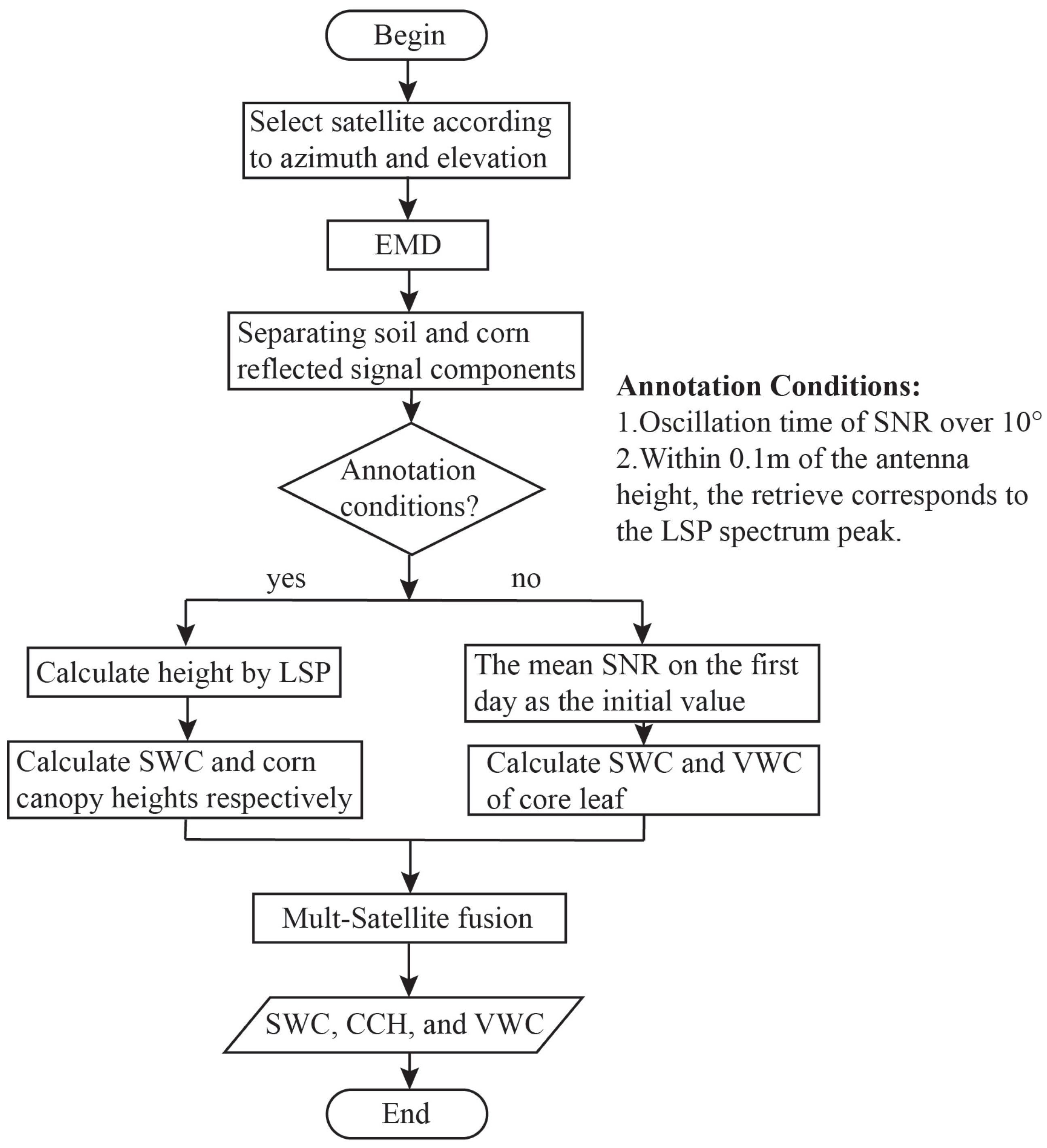
At the end of this section, we present the overall outline of the methodology used in this study. The algorithm suggested in this work, which describes the approach that enables the simultaneous measurement of CCH, VWC, and SWC, is shown in
Figure 4. To ascertain if the corn is taller than the GNSS antenna, the annotation circumstances are used in this algorithm.
Annotation conditions:
Oscillation time of the SNR over
Within 0.1 m of the antenna height, the retrieve corresponds to the LSP spectrum peak.
3. Data Process
A 77-day experiment was carried out on a cornfield in Beijing’s Tongzhou plantation in 2018 by the author’s team. The location of the test site was E and N; the altitude was 96 dm. We utilized the GPS-701-GG GNSS antenna from NovAtel, which offers an L1 signal reception for GPS + GLONASS, and the N72 GNSS receiver from CHCNAV, which can receive GPS, Beidou, GLONASS, and GALILEO, as well as multi-frequency point signals, such as L1/B1 and L2/B2. In this experiment, by using GNSS-IR technology, the LHCP signal was not taken into account and only the RHCP signal was analyzed.
The experiment site was 1600 dm wide from the east to the west and 450 dm wide from the north to the south. The 20.2 dm tall GNSS antenna was placed on the northern edge, 700 dm away from the eastern limit. Moreover, there were no towering impediments in the vicinity of the antenna. In this study, a MicroLog CS SWC detector was used. The first of three SWC in situ measurement probes was installed at the center of the experimental area, and the other two probes were positioned 300 dm on either side of the central probe. Moreover, 5 cm of soil was penetrated by each of the three probes. On the middle, east, and west sides of one corn plant, the CCH, and VWC were measured (once each). To reduce crop damage, we measured in-situ CCH rather than removing the corn from the soil for each measurement. When the corn was taller than the GNSS antenna, we selected three different corn plants from distinct locations and measured two leaves from each plant. Naturally, we avoided measuring VWC on the same corn plant twice. We frequently dried the samples for more than ten hours, depending on their water content, until a constant weight was reached. Since our experiment was conducted on a plantation, we had staff on hand to gather in situ data, and both CCH and VWC measurements were obtained in a single day.
3.1. Corn Lower than GNSS Antenna
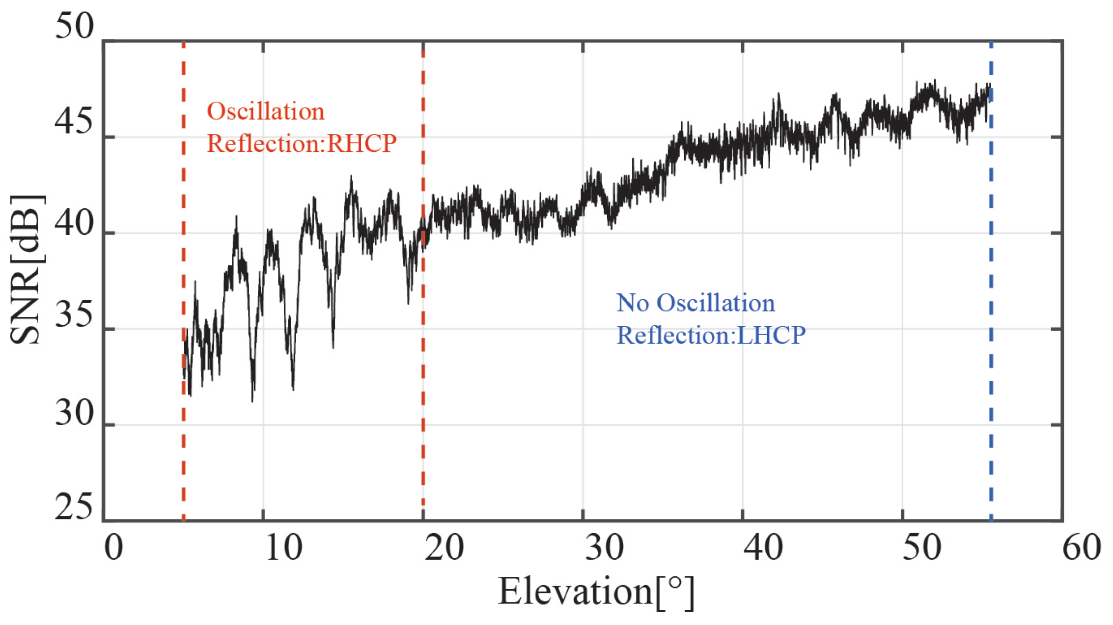
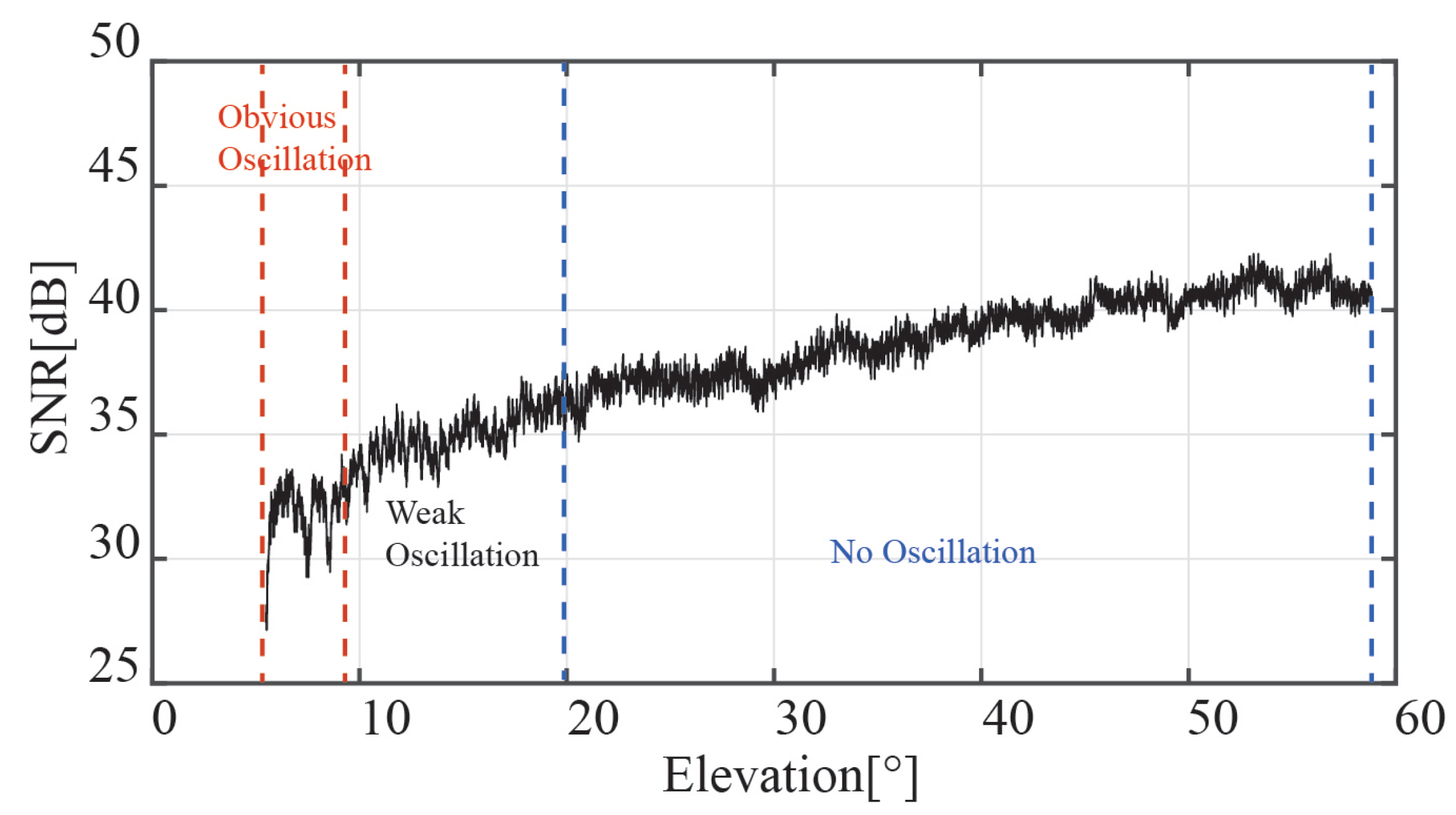
When the corn is lower than the antenna, the GNSS receiver can pick up the signal reflected by the corn canopy. The SNR of the GPS PRN2 interferometric signal is shown in
Figure 5; the x-label is the satellite elevation. The figure shows that the SNR oscillates substantially between
and
of the satellite elevation angle. Because the RHCP antenna cannot receive the reflected GNSS signals at high satellite elevation angles, the oscillation gradually disappears as the satellite elevation angle increases. To improve the accuracy of the retrieval of CCH and SWC, only the SNR data of the satellite elevation angle between
and
were selected.
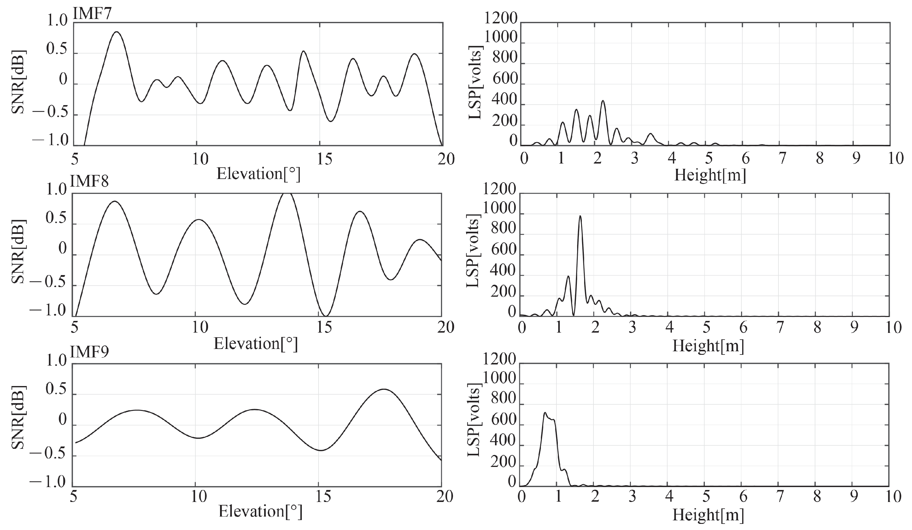
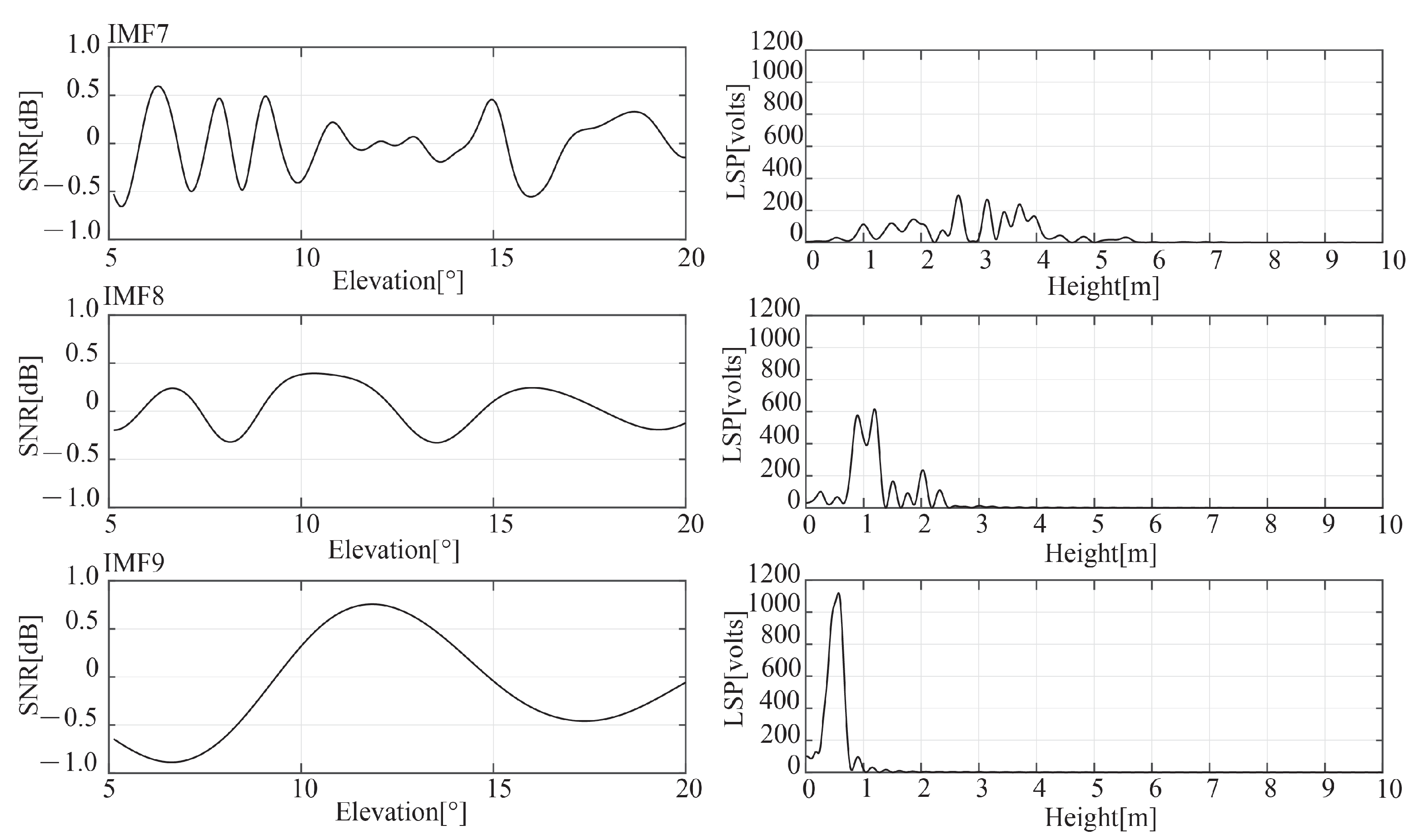
Figure 6 displays the EMD results of the GPS PRN2 (the left three panels) and the LSP spectrum’s estimation of the SNR (the right three panels). After EMD, ten frequency components were separated. The IMF7, 8, and 9 were provided, and they are shown in the figure from top to bottom. The results in
Figure 6 limited the retrieved height to a range of 0 to 10 m and the satellite elevation angle to between
and
. The effect of additional multi-path signals on the accuracy of retrieval and spurs can be significantly reduced after applying EMD, as depicted in the figure. IMF8 and IMF9, which have a single peak and larger LSP spectrum peak powers, are outperformed.
In
Figure 6, the frequency of the IMFs continuously decreases from top to bottom. While the spectrums of IMF8 and IMF9 show good isolated-peak characteristics, the spectrum of IMF7 includes significant multi-peaks at a higher frequency, which may be caused by additional multi-path signals. Furthermore, IMF8 has the biggest peak power; if we follow the methodology provided in
Section 2.4, IMF8 and IMF9 components for GPS PRN2 correspond to the reflected signals of the soil surface and corn canopy, respectively.
We only selected satellites whose azimuth angles ranged from
to
and whose elevation angles ranged from
to
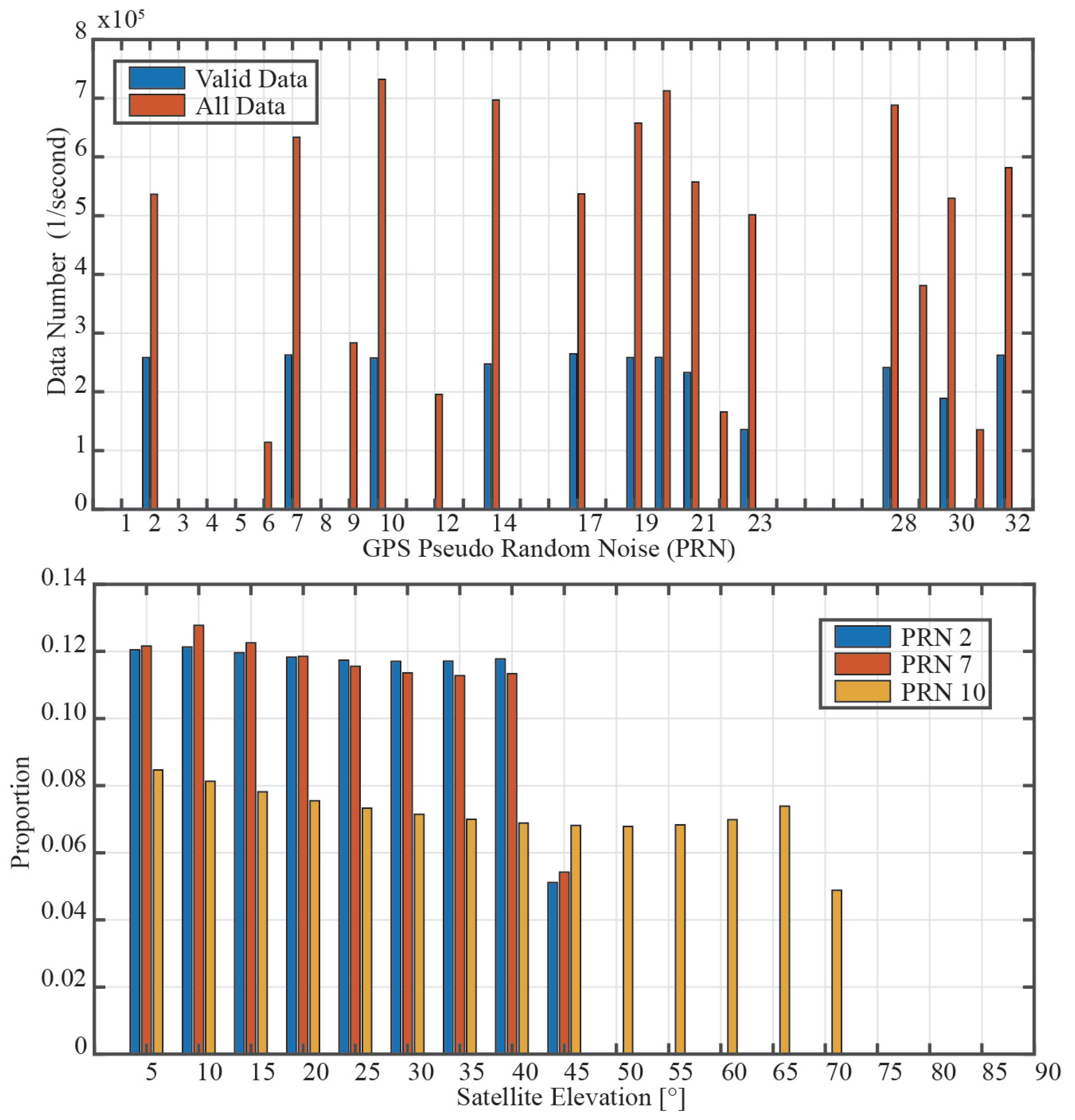
, respectively, following the orientation of the GNSS antenna that was installed at the experimental site, to minimize the impact of inaccurate data and ensure that the first Fresnel reflection area fell within the experimental area. The upper panel of
Figure 7 shows histograms of each GPS satellite’s valid data and all gathered data. We selected the GPS PRN2, 7, 10, 14, 17, 19, 20, 21, 28, and 32 as the research target satellites based on the statistical results. The data fractions of GPS PRN2, 7, and 10 at various elevation angles are shown in the bottom panel of
Figure 7, which displays the statistical results. Therefore, the study is mostly focused on the GNSS data of GPS PRN2 and PRN7 since they have more accurate GNSS data.
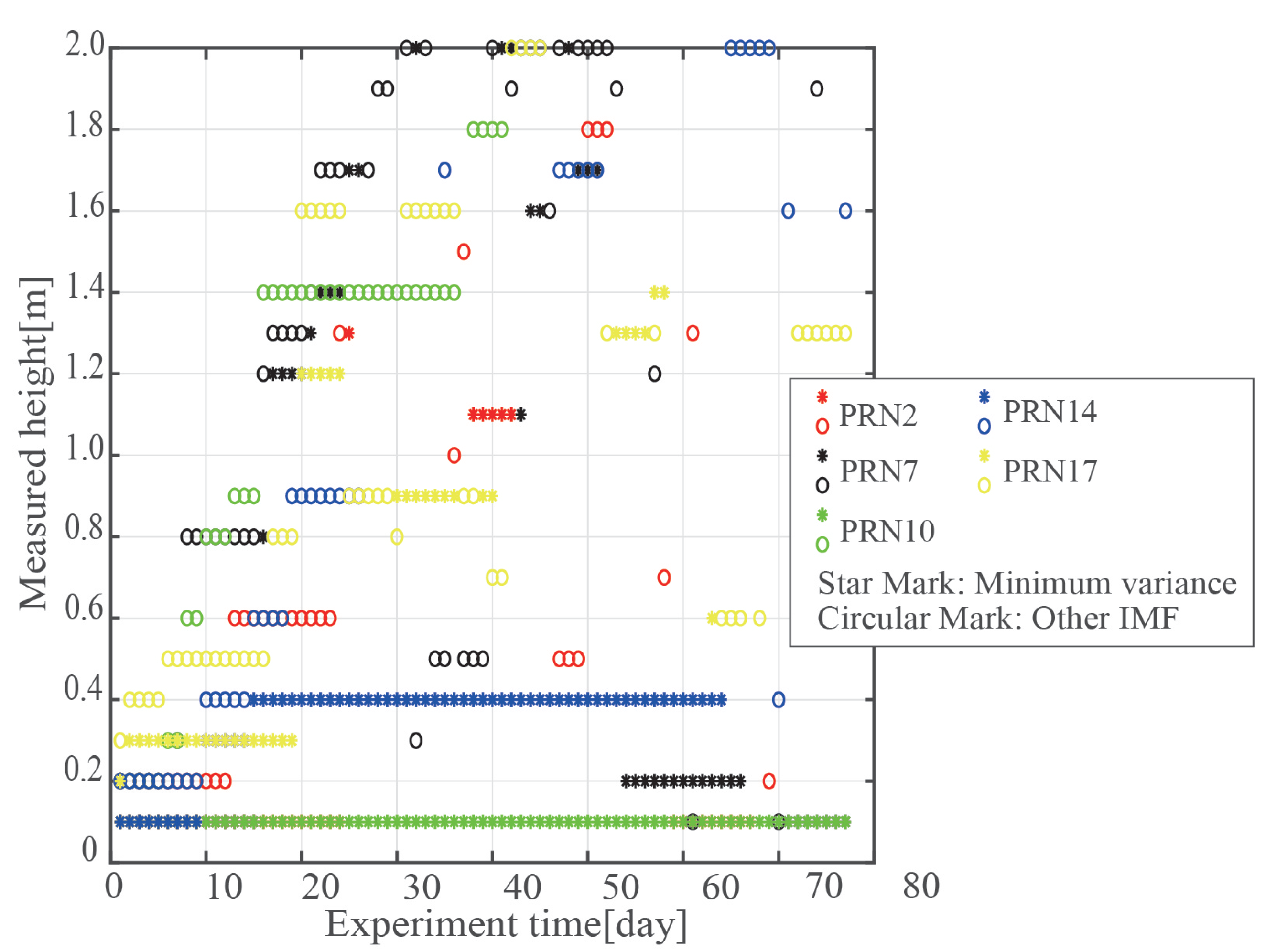
The antenna phase center is located 2.02 m above the soil surface.
Figure 8, which graphs the scatter of the interval of the retrieved height and experiment time, shows the results (PRN2, 7, 10, 14, 17, distinguished by color). The star-marked points indicate the heights with the least variance, while the circle-marked points represent the heights calculated by the other IMF. The circle-marked points steadily increase as the experiment goes on; however, the bulk of the star-marked points are distributed at low-height intervals. This demonstrates that, while the other IMF’s signal is reflected by the corn canopy, the signal of the retrieved height with the least variance is reflected by the soil surface. The ability to simultaneously retrieve SWC and CGS is then verified using the LSP spectrum peak. Due to the anisotropy of corn, the height collected by satellites with different azimuths during the same experiment changes as well. The variance is more noticeable when the corn is higher and the leaf is denser.
3.2. Corn Higher than GNSS Antenna
When the corn is taller than the GNSS antenna,
Figure 9 shows the SNR of GPS PRN2. The SNR oscillation is now less pronounced, and the observable oscillation is between
and
. Compared to the SNR of GPS PRN2 while the corn was growing, as shown in
Figure 5, the effect of the interference signal on the oscillation is not discernible, and the average power is also modest.
Figure 10 displays the SNR of the IMF7, IMF8, and IMF9 of the GPS PRN2 in DOY 228. In contrast to
Figure 6, the spectrum of the IMF8 component includes multiple peaks, and as a result of being blocked by the corn leaf, the power of each peak has diminished. Additionally, IMF9 has a single peak, which is most likely the result of reflection by the corn stalk.
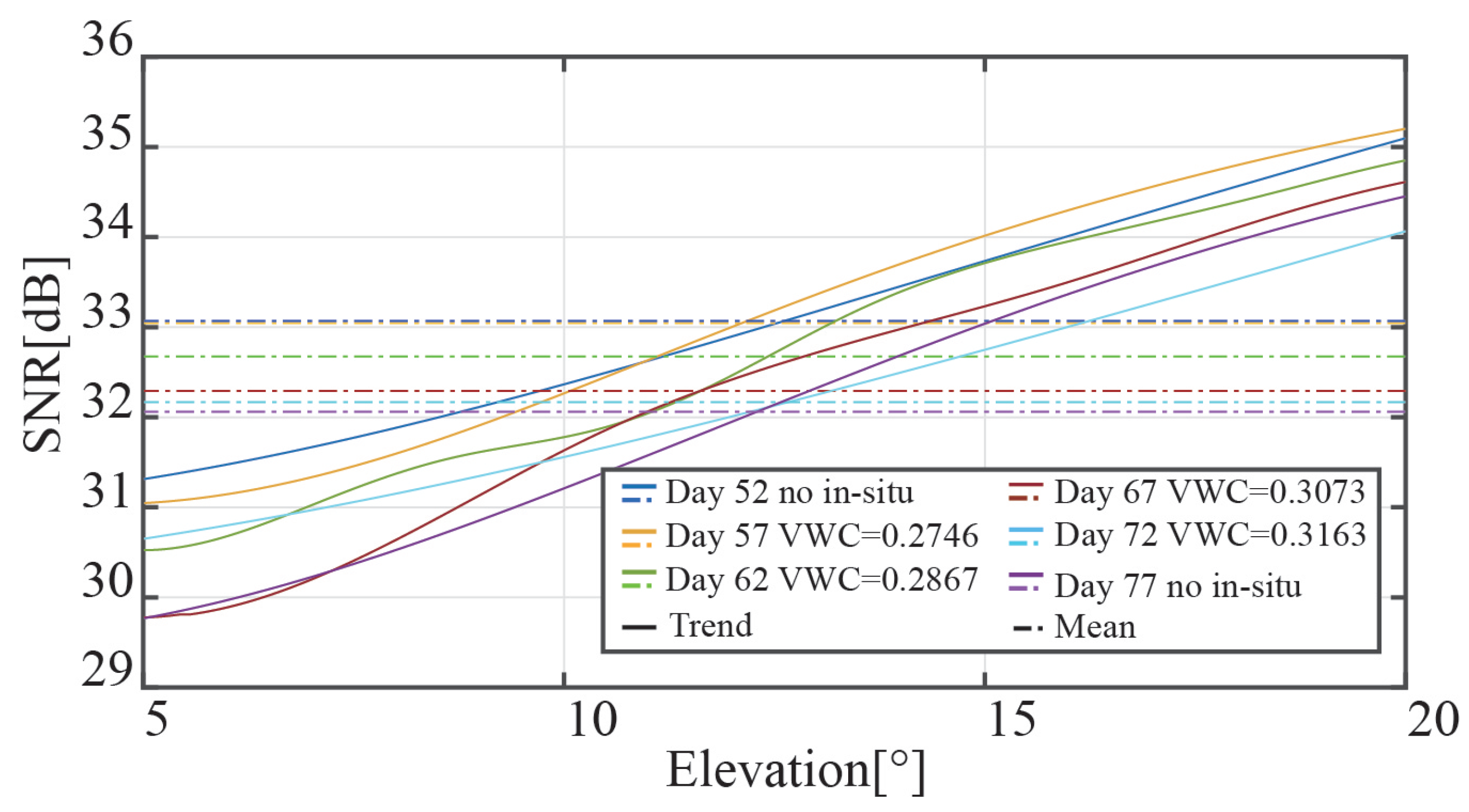
From day 55 to day 77 of the experiment, we plotted the signal power of GPS PRN2 at a five-day unit in order to visually examine the change of the signal power attenuation with CGS.
Figure 11 shows the results. To pick up the signals obstructed by the corn leaf, we chose the data of the satellite elevation angle of
to
. The same GPS satellite’s amplitude changes as the corn matures (see
Figure 11). The graphic shows the mean SNR of each direct signal as a dotted line, and it steadily decreases over the course of the experiment.
4. Results
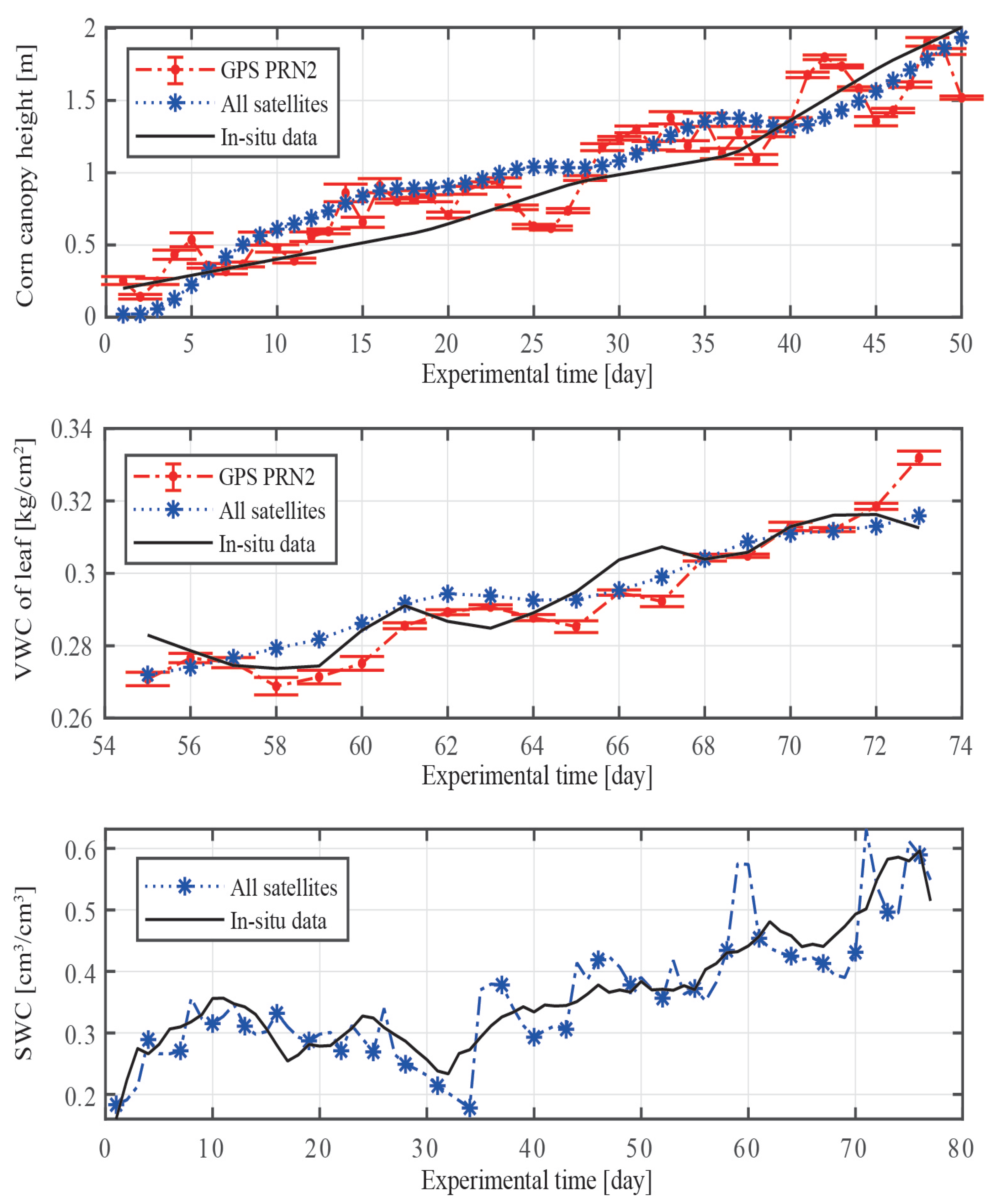
The results are shown in more detail in
Figure 12 and
Table 1 after we plot the retrieved and in situ data with an x-label for the experimental time. The results of CCH are displayed in the top panel, the results of the corn leaf’s VMC are displayed in the middle panel, and the results of SWC are displayed in the bottom panel. Moreover, the red line and blue line represent the results of GPS PRN2 and multi-GPS-satellite fusion, respectively. The two aforementioned instances show how much more accurate multi-GPS-satellite fusion is than a single satellite.
The top two panels in
Figure 12 compare the results of the fusion of different satellites with those of a single satellite (GPS PRN2). Both the data from a single satellite and those from different satellites are generally reliable, although the results from different satellites are smoother and have fewer average errors. The correlations between retrieved and in situ data for a single satellite and different satellites are
and
, as shown in the top panel, respectively. The center panel also reveals that the correlations between retrieved and in situ data for one and several satellites are
and
, respectively. The results obtained from a single satellite have significantly higher RMSE; however, the fusion of data from multiple GPS satellites may be able to effectively reduce this impact through weighting and fusion techniques.
It was noticed that the retrieval accuracy of SWC decreased when the height of the corn canopy surpassed the height of the GNSS antenna. We also used different satellite retrievals of CCH and VWC during the same time period to determine the uncertainty (type A). When the SWC was low and the VWC was large, respectively, the measurement uncertainty of CCH was the lowest and was inversely associated with the SWC.
It is important to note that the measurements of CCH are numerously larger than the in situ data in
Figure 12. When we measured the in situ CCH, we measured the height from the soil surface to the corn canopy rather than the top of the corn since the vegetation’s reflecting surface was frequently lower than the vegetation top. As a result, our in situ data will be smaller, resulting in larger CCH being retrieved using GNSS-IR than in situ CCH. Yet this problem does not exist when measuring VWC and SWC. Thus, in the follow-up inquiry, we will also look for more accurate approaches to measure the vegetation height data.
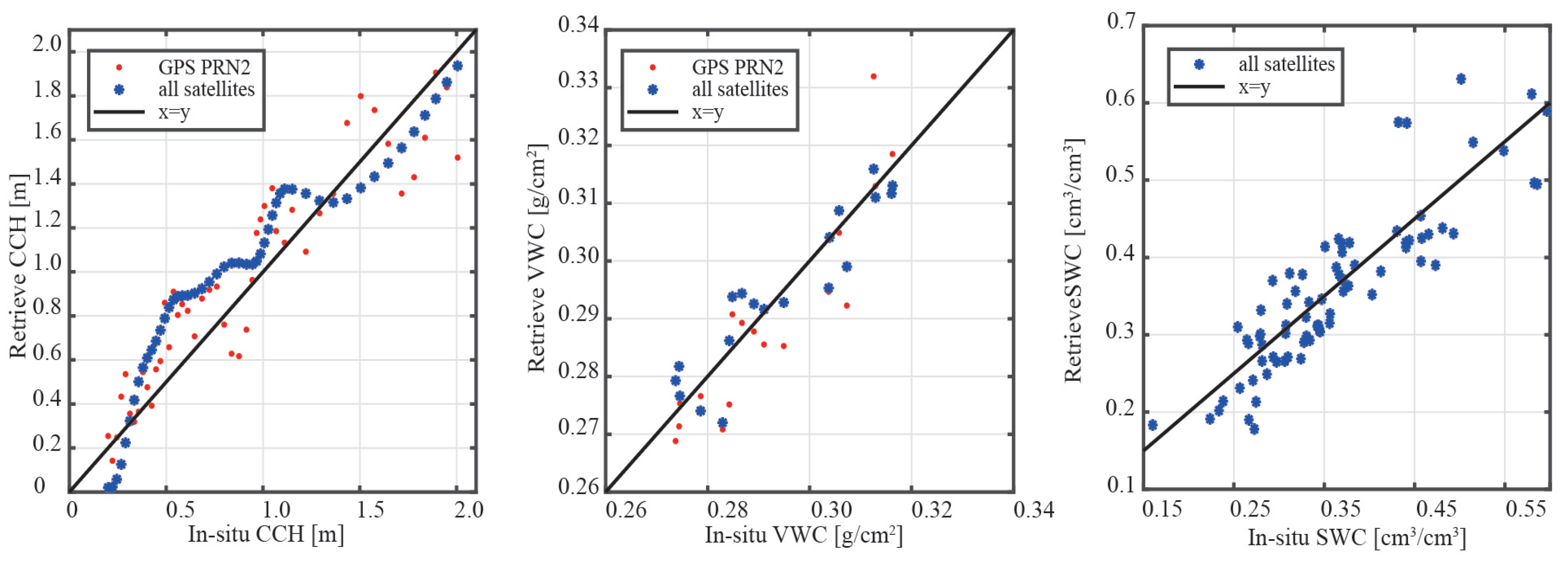
To obtain the results shown in
Figure 13, we created a scatter of the three parameters using the in situ data as the x-labels and the retrieved results as the y-labels. The panels from left to right are measured with the results of CCH, leaf VWC, and SWC, respectively. The single-satellite retrieval results are shown in the three panels by the red dots, whereas the multi-GPS-satellite fusion retrieval results are indicated by the blue star. The black line represents equation
. They were all closely related to the in situ statistics.
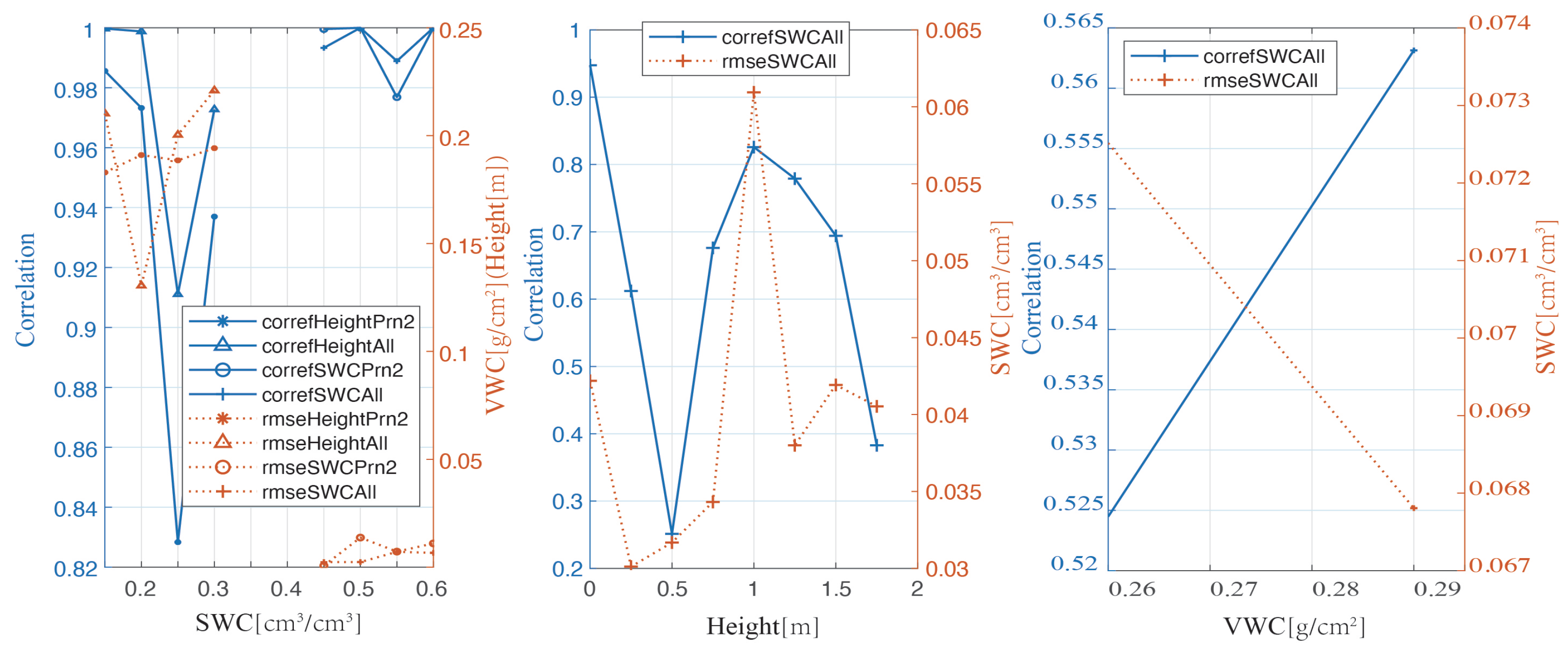
To study the influences on the measurement accuracies of CCH, VWC, and SWC, we used one of the parameters as a variable and showed the correlation and RMSE. The left, middle, and right panels are based on CCH-, VWC-, and SWC-variants; as shown in
Figure 14, both the correlation and the RMSE increase with the growth of the x-label in the left and middle panels. The association was weaker for the middle panel when the CCH was low or high. This is because, when CCH is low, corn roughens the soil surface, and when CCH is high, corn increases the signal attenuation of the soil surface reflection. However, the result is contrary to the assumption, likely because there were fewer sample points in this experiment.
5. Discussion
Researchers have made substantial progress in the retrieval of snow depth [
42,
43], vegetation height [
44], and sea height [
45]. GNSS-IR technology has been used to measure land surface and ocean parameters for decades. The different frequency components of GNSS interference signals, which transmit signals through various paths and are reflected by other objects, have received little research attention. In this study, the spectrum parameters of various signals were calculated by separating the components of GNSS-IR signals with different frequencies using EMD. We were able to distinguish between GNSS signals reflected by the soil surface and the corn canopy by comparing the estimated GNSS antenna height from different satellites with the true height at the same time. SWC and CGS were measured simultaneously using a single GNSS RHCP navigation antenna. The model used in this study demonstrated satisfactory performance in measuring the SWC, CCH, and VWC of corn leaves.
According to our research, we found that a lot of useful information may be deconstructed if analyzed utilizing different time scales following EMD. Other than the corn canopy and soil surface, we believe these signals are information-rich and may include data on the soil’s abrasiveness and the distribution of the corn stalk, stem, and leaf development. The author’s team will continue to research the best ways to effectively extract the aforementioned parameters.
As electromagnetic waves transmit objects with different dielectric characteristics, their amplitudes and phases will change. We believe that this is a trend that will continue in the remote sensing of land surface parameters in the future. As described in the introduction [
27,
28], signal power attenuation and polarization characteristics of GNSS transmission signal were used to retrieve forest parameters. Forest anisotropy is more complex, and GNSS transmission signals are more depolarized than cereals such as corn. After multiple reflections off the trunk and canopy of the vegetation, the primary polarization features of the GNSS transmission signal will be changed from RHCP to LHCP. To retrieve vegetation growth status, two GNSS antennas with different polarization properties are used to detect two polarization components and calculate their ratios to derive the cross-polarization ratio of vegetation. Future studies will concentrate on measuring the status of vegetation growth by analyzing the cross-polarization ratio of GNSS signals.
In actuality, the soil’s internal structure is fairly consistent and can be thought of as an isotropic dielectric. Based on the depolarization properties of GNSS signals, it is challenging to reverse SWC. Typically, researchers rely on the amplitude and phase characteristics of GNSS transmission signals to retrieve SWC. In order to measure the SWC, Koch et al. used the power attenuation of the GNSS transmission signal as it transmitted through the soil [
41]; they investigated how the distinctive characteristics of the GNSS transmission signal varied. At the experiment site of this study, the authors used GNSS transmission signals to retrieve SWC. The results showed that when the soil depth was 21 cm and the soil moisture was between 0.15 cm
/cm
and 0.30 cm
/cm
, the GNSS signal strength decreased to a point where it could not be detected by the GNSS sensor. Additionally, the RMSE of the retrieval using GNSS transmission signal power attenuation was less than 0.04 cm
/cm
.
The technique for measuring the VWC of corn leaves using the GNSS transmission signal power attenuation is presented in this study, and an experiment was conducted to confirm the method’s viability. Despite the brief trial time in this study, it offers a possibility for future retrieval of vegetation growth state using GNSS transmission signals. Based on this research, we will use the electromagnetic properties of GNSS transmission signals in further studies to measure vegetation growth status.
6. Conclusions
To simultaneously retrieve SWC and CGS using a single GNSS antenna, this study proposes a method that uses EMD and spectrum peak power to distinguish GNSS signals reflected by the soil surface and corn canopy. The GNSS-IR altimetry, semi-empirical model, and power attenuation were used to simultaneously measure the CCH, SWC, and corn leaf VWC. We conducted experimental verification of the method presented in this study, which can retrieve the CCH, SWC, and VWC simultaneously. The detailed conclusions are as follows:
- 1.
In this study, the spectrum of direct/reflected GNSS signals at different frequencies was separated using LSP, and then the variance of the modulus between an actual GNSS antenna height and one that was obtained from different satellites was calculated. The results show that the signal reflected by the soil surface has the least variance. This study also shows that the accuracy of the retrieval may be greatly improved by using the variance of the retrieval results as the weighting coefficient in multi-GPS-satellite fusion. The correlation between the retrieved and in situ CCH for a single GPS satellite and multi-GPS-satellite is and , respectively, and the RMSE is m and m, respectively. Moreover, the accuracy of the retrieval decreases as the SWC increases.
- 2.
To retrieve the VWC of the corn leaf when corn is higher than the GNSS antenna, this study used the power attenuation of GNSS transmission signals. To avoid receiving unoccluded GNSS signals, only satellite elevation angles between and were used. Furthermore, the multi-GPS-satellite can improve the accuracy of the corn leaf’s VWC retrieval. The correlations between the retrieved and in situ VWC for the single satellite and multi-GPS-satellite are and , and the RMSEs are kg/cm and kg/cm, respectively.
- 3.
In this study, the reflected signal was separated from the soil surface and then a semi-empirical model was used to calculate SWC. The retrieval accuracy of SWC decreases when the corn height rises due to the occlusion and attenuation of the corn leaves, according to the results. The correlation and RMSE between the retrieved and in situ SWC are and cm/cm, respectively.
Compared to what researchers have already accomplished, the model and method created in this study can simultaneously retrieve CCH and SWC utilizing a single GNSS antenna that is feasible to differentiate between bare soil and vegetation. Experiments on more crops will be conducted in later studies to further prove the feasibility of GNSS transmission signal power attenuation in retrieving vegetation parameters.

