Abstract
A nonlinear grid transformation (NGT) method is proposed for weather radar convective echo extrapolation prediction. The change in continuous echo images is regarded as a nonlinear transformation process of the grid. This process can be reproduced by defining and solving a 2 × 6 transformation matrix, and this approach can be applied to image prediction. In ideal experiments with numerical and path changes of the target, NGT produces a prediction result closer to the target than does a conventional optical flow (OF) method. In the presence of convection lines in real cases, NGT is superior to OF: the critical success index (CSI) for 40 dBZ of the echo prediction at 60 min is approximately 0.2 higher. This is due to the better estimation of the movement of the whole cloud system in the NGT results since it reflects the continuous change in the historical images. For the case with a mesoscale convective complex, the NGT results are better than the OF results, and a deep learning result is cited from a previous study for the same case for 20 and 30 dBZ. However, the result is the opposite for 40 dBZ, where the deep learning method may produce an overestimation of the stronger echo.
1. Introduction
A weather radar is an important means to monitor and warn of severe convective weather [1,2,3]. Although data assimilation of weather radar helps to improve numerical forecasting [4,5], extrapolation prediction based on weather radar echoes remains the most direct method for nowcasting a convective event, especially for mesoscale convective weather [6,7] with rapid development and dramatic changes. By means of the current observed radar data, the movement and variation of the echo are obtained, and the position and intensity of the echo in the next few minutes or longer period are estimated.
The methods of extracting radar echo moving features from horizontal two-dimensional radar images can be divided into two categories according to the target. One focuses on identifying and tracking a whole cloud, such as the Thunderstorm Identification, Tracking, Analysis, and Nowcasting algorithm (TITAN) [8]. The cloud is determined by the maximum circumscribed ellipse under a given reflectivity threshold to obtain its trajectory and variation characteristics. Another category of methods focuses on obtaining the vector field of echo movement under a uniform grid. The Tracking Radar Echo by Correlation algorithm (TREC) [9], a common algorithm in the past, determines the echo moving vector on the specified grid point based on the cross-correlation between the subunits around adjacent time points. Both TITAN and TREC contribute to a classical auto-nowcast system [3]. The Optical Flow (OF) method can also produce a vector field based on images around adjacent time points. By assuming the target gray level is constant and introducing the global smoothing condition (known as Horn-Schunk OF, [10]) or the local consistency condition (known as Lucas-Kanade OF, [11]), moving vectors can be solved based on the local change and spatial gradient of the images. A recent study shows that different nowcasting schemes based on OF can both produce better results than TREC to some extent [12]. In addition, an improved prediction method combines OF with an assimilation system and considers water content and principal component analysis [13].
However, some challenges remain in the feature extraction and extrapolation of convective clouds in the above methods. The alternating development of convective cells often occurs in convective systems. The moving direction of the whole cloud system typically depends on the combination of individual cell movement and the direction of new cell emergence, which may not be correctly reproduced by a method based on a few images at adjacent times, such as TREC and OF. Although TITAN can provide the echo movement trajectory based on longer historical echo image samples, each convective cell in a cloud system may not only move in different directions but also merge, resulting in complex topological relationships that are difficult to extrapolate. In addition, the shape and intensity of convective echoes can vary locally and rapidly, which makes it difficult to capture classical local image features such as Scale-Invariant Feature Transform (SIFT) [14] and Harris corner detectors [15]. Therefore, other image recognition and analysis algorithms based on those features cannot be effectively applied to the extrapolation of weather radar echoes. In general, there is a lack of algorithms that consider multiple historical times and do not rely on identifying individual targets.
There are also some learning methods that have been applied to radar echo and precipitation nowcasting [16,17,18,19,20,21,22,23] in recent years. These methods allow multiple observed image inputs and predict the image in the future, which appears to address the limitations mentioned above. However, since the model parameters and modeling process are implicit and there is a requirement for a large number of samples for training, the reliability of these methods requires further verification in application.
In this paper, a new method is proposed for the extrapolation and prediction of weather radar echo images. The change in continuous echo images is regarded as a nonlinear transformation process of the grid by a transformation matrix. By defining and solving this matrix, the extrapolation and prediction of the echo image can be realized. The process of establishing the new method is described in Section 2. The echo prediction experiments are shown in Section 3, including a set of ideal cases and three real cases. A summary and discussion are provided in Section 4.
2. Nonlinear Grid Transformation Method
2.1. Matrix for Grid Transformation
The concept of the transformation matrix is first introduced in this section, including the conventional transformation matrix and the extended transformation matrix used in this paper. The connection between the transformation matrix and the echo image prediction is introduced in Section 2.2 and Section 2.3.
The general form of the transformation matrix used in this paper is a matrix Mp×p, as shown in Equation (1):
where the first p − 1 rows are independent elements, the value in row p and column p is 1, and the other values in row p are 0. When p is 3, a two-dimensional point set [X1, Y1] can be transformed to [X2, Y2] as follows:
where the “1” at the third location in the square bracket provides a nonhomogeneous term when performing linear transformation of the point coordinates. Equation (2) is known as “affine transformation” [24], which is a common algorithm of image geometric transformation. With this matrix, the original point set can be translated, rotated, scaled, and deformed (sheared, stretched, etc.). For the convenience of observation, [X1, Y1] is set to an orthogonal grid, and Figure 1a shows a comprehensive example, which includes changes such as moving to the right, magnification, counterclockwise rotation, and stretching the upper right corner. This transformation is repeatable. After N-1 times left multiplication by M3×3, the transformation result [XN, YN] is obtained in the same way:

Figure 1.
Example of grid transformation from [X1, Y1] (blue grids) to [X2, Y2] (red grids) using (a) M3×3, (b) M4×4, and (c) M6×6. The black arrows represent the transformation direction of a grid.
Related principles and examples of such common 2D image transformation are seen in [24]. Note that only the first two rows of M3×3 can actually be taken if only one transformation is needed. In addition, the inverse matrix of M3×3 represents the opposite transformation. Usually, when at least three groups of X and Y before and after the transformation are known, the six parameters in M3×3 can be solved to achieve a similar transformation for other point sets, or the expected transformation can be achieved by directly specifying the 6 parameters.
However, this conventional affine transformation has a limited ability to characterize image deformation. Note that in Figure 1a, although the shape has changed to some extent, the opposite edges are still parallel, so it is obviously not suitable for characterizing the changes in weather echo images. The transformation could be expanded by adding more parameters. It is easy to extend M in the form of Equation (1). When expanding the formula with coordinates multiplied by M, the newly added variables must be known or knowable and cannot be completely linearly related to the point sequence of the original X1 and Y1. A nonlinear XY term is proposed to be added, and the transformation matrix M is 4 × 4 as follows:
An example of the transformation of Equation (4) is given in Figure 1b, which shows that it can already characterize the case where the contrast is not parallel. However, every edge of the orthogonal grid after transformation is still a straight line. To further improve the deformation ability of the transformation, the nonlinear terms X2 and Y2 are added, and a 6 × 6 transformation matrix is used:
Now, the transformation can characterize not only the translation of the grid points but also the flexible bending deformation of the original orthogonal grid (Figure 1c), which has the potential to characterize the movement and shape change of the weather echo. Therefore, Equation (5) is used as the form of nonlinear grid transformation discussed in the following sections.
2.2. Estimation of the Nonlinear Grid Transformation Matrix
As mentioned in Section 1, it is difficult to extract the target feature points that do not change with time in the weather echo image, so a pair of known and corresponding [X1, Y1] and [X2, Y2] is hard to find. Thus, a major challenge is how to solve Equation (5) to obtain the transformation matrix M6×6 when given two or more echo images.
Assuming the original image values (reflectivity values) at two adjacent times are Q1 and Q2, [X1, Y1] is the original orthogonal grid of the image, and [X2, Y2] is the point set after transformation by M6×6. Since [X2, Y2] probably does not coincide with the original orthogonal grid, let Q2* be the estimated value on [X2, Y2] of Q2. Here, Figure 1c can be taken as a simple schematic diagram, where the blue grids are [X1, Y1] and the red grids are [X2, Y2]. The pixels of Q1 and Q2 are 2D fields corresponding to the blue grids, while the pixels of Q2* correspond to the red grids. The goal of the expected transformation is to make Q1 look like Q2, where the difference between Q1 and Q2* is as small as possible after moving the image values of Q1 from [X1, Y1] to [X2, Y2]. The above objective can be expressed as minimizing Equation (6):
where the summation is for all grids of the image. However, Q2* cannot be obtained by interpolation since the transformation and [X2, Y2] are unknown in advance. Thus, an estimate of Q2* is proposed using a Taylor first-order expansion as follows:
The approximation of Equation (7) is clearly rough and does not always hold, so some additional conditions are needed. First, the grid spacing should be larger than the displacement of the object in the images. Considering that the jet velocity in convective weather is often larger than 20 m s−1, as is the outflow formed by convective precipitation, clouds may move 4.8~7.2 km or more with the wind within the interval of an operational weather radar, whose volume scan often takes 4~6 min. Therefore, the grid spacing selected for echo extrapolation should be greater than this order of magnitude, for example, at least 10 km × 10 km. Then, the echo image should be smoothed to some extent, such as via small-scale two-dimensional Gaussian filtering, to smooth the local jagged texture that may exist in the image so that the first-order partial derivative of the space in Equation (7) is representative.
After substituting Equation (7) into Equation (6), the problem of minimizing (6) can be transformed into solving a system of equations on the original orthogonal grid, where each equation is:
where ΔQ2−1 is the difference of Q2 minus Q1 on each grid. The expressions of X2 and Y2 can be obtained by expanding Equation (5) as follows:
After substituting Equations (9) and (10) into Equation (8), the nonhomogeneous linear equations of the parameters to be solved can be obtained:
where the known quantity B and the parameter M* to be solved are shown in Equations (12) and (13) as follows:
As long as more than 6 grids are satisfied, the system of equations consisting of Equation (11) can be solved by Least Squares Estimation (LSE). The obtained M* contains the elements of the first two rows of M6×6, and [X2, Y2] can then be obtained by Equation (14):
For a single transformation, the 2 × 6 transformation matrix in Equation (14) is sufficient. For the remaining 3~5 rows in M6×6, each row can be obtained by LSE after substituting [X2, Y2] into Equation (5). Thus, a method for solving the nonlinear transformation matrix is obtained when two images are given. This approach is also applicable to multiple images. For example, for the case of three images, Equation (11) on each grid using the first and second images is first listed in the system of equations, then that of the second and third images are appended to the system of equations, and finally, they are solved together via LSE. This process enables the final transformation matrix to reflect the continuous movement and deformation characteristics of multiple images.
There are four more points to note:
- (1)
- Quadratic coordinates and distance derivatives are involved in the operation of Equation (11), which makes it possible for the value of the coefficient to span many orders of magnitude. Therefore, all the variables involved in the actual calculation should be at least double-precision floating-point numbers.
- (2)
- An underestimation of image change will occur if points of ΔQ2−1 = 0 are considered when preparing Equation (11) because when only points of ΔQ2−1 = 0 are used, the final obtained M6×6 will be a unit matrix, that is, the image is unchanged.
- (3)
- Although the time complexity for solving Equation (11) appears to increase quadratically with the number of grids, the size of the original image does not become a problem because the method is not based on detailed texture and rather requires a certain degree of coarse grid spacing. A current personal computer can complete the calculation in 1–10 s when the historical sequence length is approximately 10, and the number of grid points is less than 100 × 100.
- (4)
- After obtaining the transformation matrix and before extrapolating using Equation (14), the image and coordinates are replaceable. For example, the filtered coarse-resolution image can be replaced by the original fine-resolution image. However, the unit of coordinates cannot be replaced because the transformation matrix is based on the coordinates used. For example, the coordinates cannot be changed from rectangular coordinate distance to latitude and longitude once the transformation matrix is obtained or from the latitude and longitude of a region to another different region.
2.3. Practical Steps for Extrapolation Prediction
An ideal extrapolation prediction scheme is to first find M6×6 and obtain the transformation matrix after multiplication according to the time N that needs to be extrapolated, which is similar to Equation (3). Then, the inverse matrix is produced, and the discrete point set of reverse extrapolation is obtained and used for backward interpolation. Finally, the predicted image is obtained directly by linear interpolation. However, during the experiment for constructing the new method in this paper, some anomalies caused by nonlinear effects when N was large (such as greater than 10) were found. For example, the image does not further deform or move as expected but rolls back. Therefore, a more reliable extrapolation method is proposed.
First, only M2×6 is obtained using Equation (11). Then, [X2, Y2] are obtained using Equation (14), and [X1, Y1] are subtracted from [X2, Y2] to find a vector field u and v to represent the one-time grid transformation. According to the time N to be extrapolated, the original grid points are moved in the opposite direction of u and v in N steps, and u and v on the new discrete points are interpolated in each step, which is known as backward interpolation. The values of the final backward positions are obtained by linear interpolation and are deemed to appear on the orthogonal grid point after N steps; thus, the predicted image is obtained. Although this process is somewhat different from a direct transformation similar to Equation (3), it can reflect the grid movement and deformation characteristics generated by the solved transformation matrix, and there is no abnormality caused by nonlinear effects.
The above introduces the image extrapolation method proposed in this paper, called the Nonlinear Grid Transformation (NGT) method. The main steps of echo extrapolation prediction are supplemented and summarized as follows:
- (1)
- Prepare a set of time-continuous historical echo images prior to the start time of the prediction. Perform resolution reduction and two-dimensional Gaussian filtering if necessary.
- (2)
- For each pair of adjacent images, each Equation (11) from a grid in which ΔQ2−1 ≠ 0 is selected continuously to form a system of linear equations.
- (3)
- Solve the system of linear equations in the last step to obtain the transformation matrix M2×6. Obtain [X2, Y2] according to Equation (14), and subtract the origin orthogonal grid [X1, Y1] to obtain grid transformation vector fields u and v. Here, the u and v are generated one-time.
- (4)
- If a resolution reduction is applied in the first step, u and v are linearly interpolated to the original resolution.
- (5)
- Based on the original image at the start time of the prediction, u and v are used to conduct backward interpolation, and the extrapolation image at N steps is obtained.
3. Weather Radar Echo Prediction Experiments
3.1. Experimental Setting
3.1.1. Case Setting and Statistics
To examine the proposed NGT method, a set of ideal cases and three real cases are used. In the ideal experiment, a simple two-dimensional normal distribution image with an extreme value region is used to simulate the echo of a precipitation cloud. Some simple changes, such as moving or numerically changing, are added to the images to test whether NGT can achieve the expected results. The three experiments using real radar observations are based on different radars and convective weather events. The original input echo images have a range of 600 km × 600 km and a resolution of 1 km × 1 km. The data form of these images is Constant Altitude Plan Position Indicator (CAPPI) or composite reflectivity, whose details are provided in Section 3.3, Section 3.4 and Section 3.5.
For real cases, three commonly used skill scores, namely, the critical success index (CSI, also known as the threat score), the probability of detection (POD), and the false alarm ratio (FAR), are used to examine the prediction results [25]. These skill scores are calculated as follows:
where NA is the number of grid points with successful predictions (the hit number) for which both the observation and prediction are greater than a given threshold; NB is the number of grid points with false alarms for which the observation is less than the given threshold, and the prediction is greater than the given threshold; and NC is the number of grid points with unsuccessful predictions, for which the condition is opposite to NB. Referring to previous studies [18,19], the thresholds of radar reflectivity (Z) on the echo image are set to 20, 30, and 40 dBZ. A perfect prediction result has a CSI and POD close to 1 and a FAR close to 0. CSI is the overall statistic, while POD and FAR help to further explain, for example, whether a lower CSI is due mainly to a low hit rate or a high false alarm rate.
When comparing the CSI of different methods, a static reference value is additionally calculated, where the CSI of this static reference is obtained without processing the image at the starting time of the prediction. The purpose of doing so is to test the effectiveness of the CSI in the prediction results. Specifically, for clouds with a large range or inconspicuous movement, higher CSI may be obtained even without any echo extrapolation. Therefore, an effective prediction result should have a CSI larger than the static reference at the same time; otherwise, it should be regarded as a quantitative result with a negative effect.
3.1.2. The Method for Comparison
A method that can also output the image moving vector field is to be selected for comparison to examine whether the image prediction is improved by the newly proposed NGT method. Note that TREC and OF can both fulfill that. However, OF has lower computational complexity than TREC at the same resolution, and some recent studies indicate that OF makes better predictions [12]. Therefore, a simple and feasible OF scheme is adopted. A global smoothing constraint condition of Horn-Schunk OF [10,26] is implemented, and the minimizing function is Equation (18):
where Ω is the area domain of grid points, It, Ix, and Iy are the temporal and spatial partial derivatives that synthesize two adjacent times, and α2 is a smoothing parameter. The iterative scheme to solve the optical flow vector fields u and v is as follows:
where and are the regional average values of u and v, respectively, and the superscripts n and n + 1 represent the order of iterations. Here, α2 is set to the global average of Ix2 + Iy2. The number of iterations is 1000 to ensure the solution instead of setting a breakdown condition. More details about the calculation scheme of It, Ix, Iy, , and the boundary are provided in [26].
The OF adopts a similar method as the NGT, where the vector fields u and v for extrapolation are obtained first, and then backward interpolation is used on the image at the predicted time. For real cases, the solving of u and v is performed under an average grid of 10 km × 10 km. An additional two-dimensional Gaussian filter with a standard deviation of 1 grid and a radius of 10 grid is applied to NGT. The prediction is under the resolution of the original 1 km × 1 km grid. Images of the prediction start time and the previous time are used as historical samples in OF, while NGT uses historical samples one hour ahead of the prediction start time. The impact of historical sample selection on OF is briefly discussed in Section 3.2, and the impact of historical sample length on NGT is briefly discussed at the end of Section 3.3.
3.2. Ideal Cases
As shown in Figure 2a, both NGT and OF can make basically accurate predictions when only a simple translation exists. This also shows that the OF extrapolation scheme used for comparison in this paper is reliable for simple prediction.

Figure 2.
Example of extrapolation results in ideal experiments based on simple images: (a) only translation, (b) add increment, and (c) direction change. Samples are two-dimensional normal distribution images with an initial value range of 0~1, and contour lines for 0.5 are shown. The translation speed in (a) and (b) is 0.5 grids per time in both the X and Y directions. A 0.01 increment over time is added in (b). The rotation speed of the extreme center in (c) is 3 degrees per time. The historical samples shown are t = 1~10, the predictions start from t = 10, and the object is at t = 20. NGT is modeled using all ten historical samples, while OF uses only t = 9~10. The X and Y axes are distances with arbitrary units.
When the image value has a time increment (Figure 2b), although the results of the two methods are both biased, the result of NGT is closer to the target object, while OF has almost more than twice the deviation, possibly due to the time increment, which does not conform to the basic assumption of the OF method itself.
When the moving path of the target object has an arc with rotation characteristics (Figure 2c), the result of NGT is closer to the target, while the result of OF seems to be only a linear extrapolation of the historical sample trajectory, resulting in an obvious deviation. In addition, it can be expected that the change in the historical sample selection will produce different OF results, where the predicted red circle will appear at the extension lines of the central positions of the two historical samples, which is still farther from the target. That is, the OF method is weak at extrapolating this path turning, regardless of how historical samples are selected. Note that the use of more than two historical samples for OF in [12] is expected also not helpful under this condition since it does not change the algorithm feature. In summary, compared with the conventional OF method, NGT can perceive more image changes from historical samples and can obtain more accurate extrapolation prediction results when the target value and path change.
The deviation of the NGT should also be noted. It is seen from Section 2.2 that only the spatial derivatives and coordinates of the image are involved in NGT, while the simple target used in Figure 2 has similar spatial derivatives in all directions, which might bring confusion and cause deviation. However, since this defect does not exist in real cases, it is no longer discussed below.
3.3. Real Case 1: A Convective Line with Shape Evolution
A convective weather event with obvious movement and shape change in radar echo images is selected first. A squall line event occurred in the U.S. on 20 May 2011, which was analyzed in a previous study [27]. The stage is selected in which a convective line is detected by a NEXRAD S-band radar (the station code is KTLX, located at 97.28°W, 35.33°N) when this convective line with shape-shifting moves to the radar. This radar performs a volume scan consisting of 15 elevations in 255 s. The CAPPI at a height of 3 km is obtained by triple linear interpolation from the volume scan data, which can not only reflect the main movement of the echo but also automatically shield most of the clutter in the boundary layer.
As shown in Figure 3, the convection line and its strong echo front are first in an inverted L-shape. As the cloud system moves northeastward, the convection line gradually evolves into a bow shape. Due to the north side of the cloud body moving out of the radar detection range, the original inverted L-shaped east–west echo band also gradually disappears. The visual moving directions of cells, new cells emerging and the whole cloud system are marked in Figure 3a. The horizontal wind U and V from ERA5 reanalysis data (Figure 4) are cited as a physical wind field for comparison with NGT and OF to analyze their features. The direction of new cell emergence is toward the southeast side, which is the windward direction of the relatively low level (e.g., 950 hPa), while the direction of the cell movement at a height of 3 km is along the north and slightly eastward, basically the same as that of the wind field at a similar height (from 850 hPa to 700 hPa). The combination of the above two directions eventually makes the whole cloud system move northeast.
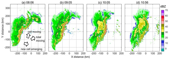
Figure 3.
CAPPI at a height of 3 km observed by KTLX radar on 20 May 2011. X and Y represent west–east and south–north distances relative to the radar site. (a) 08:06; (b) 09:05; (c) 10:05; (d) 10:56. The time is in UTC. The black arrows in (a) represent the visual directions of cell movement, new cell emergence, and total movement of the whole system.
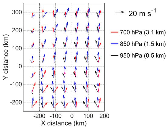
Figure 4.
Wind field from ERA5 reanalysis data at 09:00 UTC.
Taking a 60 min prediction as an example, the data in Figure 3b are taken as the starting time, and Figure 3c is taken as the prediction target where the convection line moves and deforms. The results of NGT are basically consistent with the observed front edge of the convective line (Figure 5a). The grid transformation vectors mainly point to the northeast, which is consistent with the overall movement direction of the cloud system. In addition, these vectors point to the west at the northernmost point, which is also consistent with the image change characteristics of the weakening and disappearance of the east–west echo band on the north side in Figure 3. On the other hand, the OF results obviously underestimate the movement of the convection line (Figure 5b). The vector value of OF on the southeast side is small, which may be related to the interference of small-scale scattered clouds in the clear sky region at the front. More importantly, although the vector field of OF is similar to the wind field at the front of the convective line, pointing north and similar to the direction of monomer movement, this is not the direction of the overall cloud movement, which may be the main reason for the underestimation of movement.
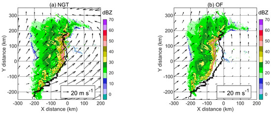
Figure 5.
Sixty-minute prediction results. The target time is 10:05 UTC on 20 May 2011. The shading is the predicted CAPPI at a height of 3 km. The black solid lines are the 30 dBZ leading edge of the convective echo observed at the target time (Figure 3c). The vector fields are obtained by NGT and OF for backward interpolation. (a) NGT; (b) OF.
Although the prediction effect decreases with time, there are differences between the two methods (Figure 6). The CSI of NGT is lower than that of OF only in the first 1–3 times of prediction and is better than that of OF in other prediction periods. For the higher 40 dBZ echo, NGT has the most obvious advantage over OF, and the CSI can be 0.2 higher than that of OF in the 40~60 min prediction period. The CSI of OF for 30 and 40 dBZ is lower than the static references within 60 min, which means that the prediction accuracy loses its value, while the CSI of NGT decreases more smoothly, indicating that it has the capability to perform echo prediction over a longer prediction period. In addition, due to the overall deviation of the position of the convective line predicted by OF, its prediction skill scores are all lower than those of NGT (Table 1).
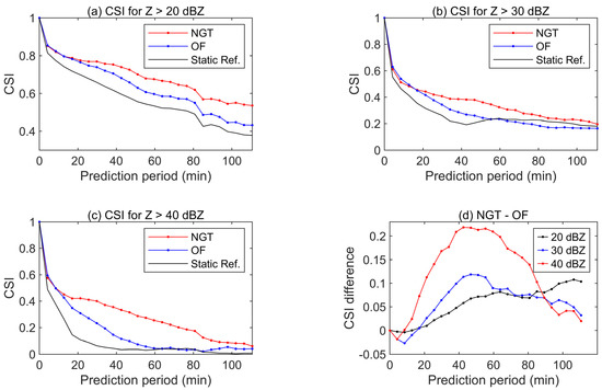
Figure 6.
CSI of the prediction by NGT and OF for (a) Z > 20 dBZ, (b) Z > 30 dBZ, (c) Z > 40 dBZ, and (d) NGT—OF. The prediction starts at 9:05 UTC on 20 May 2011. The “static ref.” lines mean a reference without any extrapolation on the data of the starting time.

Table 1.
Skill scores of the two methods for 60 min prediction. The target time is 10:05 UTC on 20 May 2011.
Figure 7 briefly shows the effect of historical sample length on NGT. The CSI is lower when only two historical samples (less than 5 min in this case) are taken. With an increase in the length of the historical sample, the CSI rises in oscillation first and then rises slowly when the sample is longer than 20~30 min, indicating that a longer sample length leads to a better NGT prediction effect. However, since the duration of convective weather is usually only a few hours or less, it is not practical to use historical samples longer than 60 min. Therefore, only 60 min of the historical sample for NGT is used and discussed in most parts of this paper.

Figure 7.
The CSI of 60 min prediction by NGT using different time lengths of historical samples for (a) Z > 20 dBZ, (b) Z > 30 dBZ, and (c) Z > 40 dBZ. The prediction starts at 9:05 UTC on 20 May 2011.
3.4. Real Case 2: A Convective Event with Convective Line Formation
To examine whether the NGT is always better than OF in different stages of a convective event, it is necessary to select a case that has been detected by radar for a more complete life cycle. The selected case is a convective event that occurred in Shandong Province, China, on 17 May 2020. The radar data are from a CINRAD-SA type S-band radar (the station number is Z9532, located at 120.23°E, 35.99°N). This radar performs a volume scan consisting of 9 elevations within 342 s. Other information is provided in [28]. The CAPPI at 3 km height is used for analysis, similar to the last case in Section 3.3.
As shown in Figure 8, scattered convective clouds appear at the northwest side of the radar first, develop into a severe convective cell group, and then form a convective line, passing over the radar origin and moving southeastward. In the following time, the stratiform cloud area at the back of the convection line gradually expands, and the strong echo at the front gradually weakens, which is no longer displayed together here.
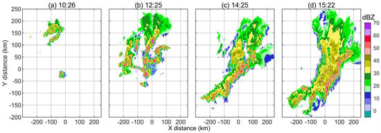
Figure 8.
CAPPI at 3 km height observed by Z9532 radar on 17 May 2020. X and Y represent west–east and south–north distances relative to the radar site. (a) 10:26; (b) 12:25; (c) 14:25; (d) 16:59. The time is in UTC.
Figure 9 shows the 60 min prediction skill scores of almost the entire weather process. Clearly, NGT is not always superior to OF in echo prediction for 20 and 30 dBZ. However, the CSI of NGT for 40 dBZ is higher than that of OF at the target time of 14~16 UTC, which is the stage where the convective line exists.
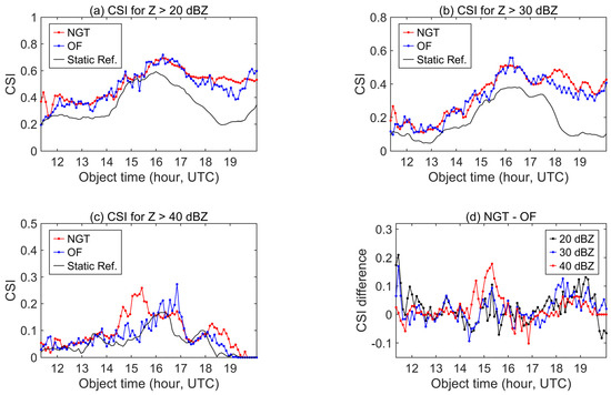
Figure 9.
CSI of the 60 min extrapolating prediction by NGT and OF for (a) Z > 20 dBZ, (b) Z > 30 dBZ, (c) Z > 40 dBZ, and (d) NGT—OF on 17 May 2020. The prediction starts at 9:05 UTC on 20 May 2011.
A one-hour prediction is taken as an example for analysis similar to Section 3.3, where the data in Figure 8c are taken as the starting time, and Figure 8d is taken as the prediction target when the convection line persists. Note that 57 min is used here to represent a one-hour period since there is no data point exactly at the next 60 min. The NGT results show that the predicted convective lines are basically consistent with the observations (Figure 10a). Note that there is a large grid transformation vector over the normal wind speed in the clear sky area on the southeast side of the convective line pointing to the southeast, which indicates that the image is greatly stretched southeastward in the prediction. However, in the OF results (Figure 10b), an underestimation of the movement of the convective line remains. This underestimation is similar to that in Section 3.3 and is thus also due to the deviation of the moving direction of the whole cloud system and cells. In this 60 min prediction example, the CSI of NGT is better than that of OF (Figure 11), and the advantage is most obvious for 40 dBZ. Regarding the other skill scores, only the FAR of NGT is inferior to that of OF for 20 and 30 dBZ (Table 2). This may be due to the increase in the false alarm rate of NGT caused by a displacement greater than the expected echo at X = 0~100 km and Y = −200~−100 km in Figure 10a, but this does not affect the overall advantage of NGT.
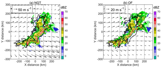
Figure 10.
Fifty-seven-minute prediction results. The target time is 15:22 UTC on 17 May 2020. The shading is the predicted CAPPI at a height of 3 km. The black solid lines are the 30 dBZ contours of the convective echo observed at the target time (Figure 8c). The vector fields are obtained by NGT and OF for backward interpolation. (a) NGT; (b) OF.
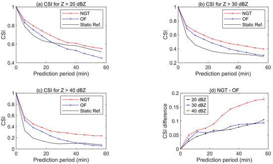
Figure 11.
CSI of the prediction by NGT and OF for (a) Z > 20 dBZ, (b) Z > 30 dBZ, (c) Z > 40 dBZ, and (d) NGT—OF. The prediction starts at 14:25 UTC on 17 May 2020.

Table 2.
Skill scores of the two methods for 60 min prediction. The target time is 15:22 UTC on 17 May 2020.
3.5. Real Case 3: A Mesoscale Convective Complex and Comparison with Previous Deep Learning Results
As a newly proposed method, NGT must be tested in different types of convective weather, and it is best to compare it with other newer popular methods. We have identified a case that can approximately meet this goal. A convective weather process dominated by a Mesoscale Convective Complex (MCC) occurred in Hebei Province, China, on 21 June 2017. A 30 min prediction result was presented in previous deep learning studies by Liang et al. [18] and Han et al. [19], where 8 years of data were used for training and 30 min of historical data were inputted to generate predictions. They mainly used a U-Net model, which is a convolutional neural network and is constructed by stacking downsampling and upsampling convolutional modules yielding a unique U-shape network architecture. The table of skill scores was given in [18] for this prediction example. Therefore, it is possible to compare NGT with the previous deep learning method by collecting the same radar data and repeating only the 30-min predictions during the same prediction period instead of collecting a large number of training datasets to reproduce the deep learning result or directly citing the resulting images, which is not applicable. The radar echo image used in [18] is composite reflectivity, which is a combination of six operational radars. The station numbers are Z9010, Z9220, Z9311, Z9313, Z9314, and Z9335, where Z9313 and Z9314 are CINRAD-CB type, and others are CINRAD-SA type. The time interval of the image is 6 min.
The observation at the target time and the prediction results of NGT and OF are shown in Figure 12, while the results of the deep learning method under the same prediction conditions are seen in [18]. The differences between the observation and the prediction results from both NGT and OF seem no longer as obvious as shown in the above two sections. For the CSI (Figure 13), the results of NGT and OF are very close, where NGT is slightly higher for 20 and 30 dBZ. In addition, the CSIs of NGT and OF are only slightly higher than the static reference, indicating that the prediction of echo movement is limited. Considering that the OF method is sensitive to the instantaneous movement of the cloud, these results indicate that the movement itself of MCC is not as obvious as the squall lines referred to in the last sections. More importantly, the deep learning method appears to be a more advanced method with results better than those of NGT and OF for 40 dBZ; however, its CSI for 20 and 30 dBZ is not only worse than that of NGT and OF but also worse than the static reference, which indicates that it may not correctly reflect the movement of the echo.

Figure 12.
(a) Composite reflectivity obtained by multiple radars at 11:30 UTC (target time) on 21 June 2017 and 30 min prediction results by (b) NGT and (c) OF.
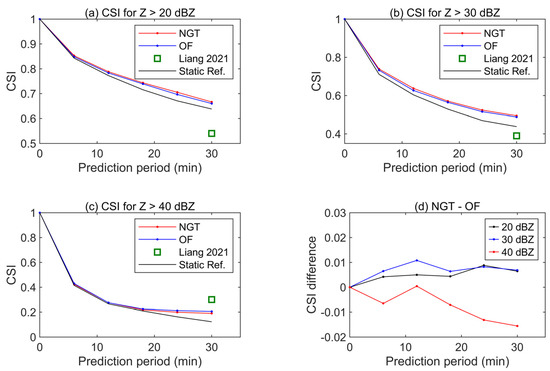
Figure 13.
CSI of the prediction by NGT and OF for (a) Z > 20 dBZ, (b) Z > 30 dBZ, (c) Z > 40 dBZ, and (d) NGT—OF. The prediction starts at 11:00 UTC on 21 June 2017. Liang 2021 is cited from [18] as a deep learning method for comparison.
As shown in the skill scores (Table 3), although the POD of this deep learning method at 20 and 30 dBZ is the highest, the FAR is also higher than that of the other two methods. That is, both the hit rate and false rate are high, indicating an overestimation of the reflectivity of the echo images. This overestimation is seen in the image in Liang et al. (2021) and might be one of the reasons that the deep learning method obtains a better skill score for a larger echo threshold.

Table 3.
Skill scores of two methods for 30 min prediction and the comparison with results from a previous deep learning study. The target time is 11:30 UTC on 21 June 2017.
4. Conclusions
The NGT method is proposed for weather radar convective echo extrapolation prediction. A set of ideal experiments and three real echo extrapolation experiments were performed to demonstrate the performance of the new method. The results are compared with those from an optical flow (OF) method, and a brief comparison with a previous study based on a deep learning method is conducted in a real case. The main conclusions are as follows.
- (1)
- In the ideal experiments for simple targets, NGT can achieve better prediction results than OF when there are changes in the value and path of the image target.
- (2)
- For cases with a convective line, NGT is superior to OF, where the CSI for 40 dBZ of the echo prediction at 60 min is approximately 0.2 higher.
- (3)
- For the case of MCC, NGT is better than OF and a deep learning method for 20 and 30 dBZ, while the deep learning method produces the best skill score for 40 dBZ. However, the good performance of the deep learning method may be due to the overestimation of the stronger echo.
The conventional OF method is based on a few historical data samples, tending to present the instantaneous movement direction of convective cells. Therefore, although the results of OF are closer to the physical motion of a cloud, there is a deviation compared with the movement of the overall cloud system. On the other hand, NGT can be modeled based on historical 60 min data. Although the grid transformation vector of the NGT is generally different from the physical wind field, the results are closer to the continuous variation characteristics of the echo image. Therefore, the movement and variation pattern of the whole convection line can be predicted more approximately.
In general, NGT, as a new method, improves the prediction effect of at least one type of convective system. This improvement in nowcasting capability can help to respond to severe convective weather, such as making corresponding changes to outdoor activities and transportation plans and better arranging artificial hail suppression operations.
However, many studies must be conducted in the future. The sensitivity of the prediction effect to the parameters in the prediction method needs to be further studied. More importantly, the CSIs of NGT and OF for stronger echo are still low and are markedly less than those for weaker echoes, which may be caused by the spatial nonuniformity and the strength variation of convective echoes. Therefore, an extrapolation of the echo strength may be needed to improve the result. Moreover, since deep learning methods have the potential to better predict the increase in echo strength, more operational observation cases are needed for further study to take full advantage of different prediction methods.
Author Contributions
Conceptualization, Y.S. and Y.T.; methodology, Y.S. and H.X.; software, Y.S.; validation, Y.S.; formal analysis, Y.S. and H.X.; investigation, Y.S.; resources, H.X., Y.T. and H.Y.; data curation, Y.T. and H.Y.; writing—original draft preparation, Y.S.; writing—review and editing, H.X., Y.T. and H.Y.; visualization, Y.S.; supervision, H.X.; project administration, H.X.; funding acquisition, Y.S., H.X. and H.Y. All authors have read and agreed to the published version of the manuscript.
Funding
This research was supported in part by the National Key Research and Development Plan of China (grant no. 2019YFC1510304), the National Natural Science Foundation of China (grant no. 42105127), the Research and Experiment on the Construction Project of Weather Modification Ability in Central China (grant no. ZQC-T22254), and the Special Research Assistant Project of Chinese Academy of Sciences.
Data Availability Statement
Data are available in a publicly accessible repository that does not issue DOIs. Publicly available datasets were analyzed in this study. The NEXRAD radar base data used in Section 3.3 can be found at https://www.ncdc.noaa.gov/nexradinv/map.jsp, accessed on 7 February 2023. Other data sharing is not applicable.
Conflicts of Interest
The authors declare no conflict of interest.
References
- Wilson, J.W.; Crook, N.A.; Mueller, C.K.; Sun, J.Z.; Dixon, M. Nowcasting Thunderstorms: A Status Report. Bull. Am. Meteorol. Soc. 1998, 79, 2079–2099. [Google Scholar] [CrossRef]
- Schumacher, R.S.; Rasmussen, K.L. The formation, character and changing nature of mesoscale convective systems. Nat. Rev. Earth Environ. 2020, 1, 300–314. [Google Scholar] [CrossRef]
- Mueller, C.; Saxen, T.; Roberts, R.; Wilson, J.; Betancourt, T.; Dettling, S.; Oien, N.; Yee, J. NCAR Auto-Nowcast System. Wea. Forecast. 2003, 18, 545–561. [Google Scholar] [CrossRef]
- Sun, J.Z.; Wang, H.L. WRF-ARW Variational Storm-Scale Data Assimilation: Current Capabilities and Future Developments. Adv. Meteorol. 2013, 2013, 13. [Google Scholar] [CrossRef]
- Dance, S.L.; Ballard, S.P.; Bannister, R.N.; Clark, P.; Cloke, H.L.; Darlington, T.; Flack, D.L.A.; Gray, S.L.; Hawkness-Smith, L.; Husnoo, N.; et al. Improvements in Forecasting Intense Rainfall: Results from the FRANC (Forecasting Rainfall Exploiting New Data Assimilation Techniques and Novel Observations of Convection) Project. Atmosphere 2019, 10, 125. [Google Scholar] [CrossRef]
- Roy, S.S.; Mohapatra, M.; Tyagi, A.; Bhowmik, S.K.R. A review of Nowcasting of convective weather over the Indian region. Mausam 2019, 70, 465–484. [Google Scholar] [CrossRef]
- Sokol, Z.; Szturc, J.; Orellana-Alvear, J.; Popová, J.; Jurczyk, A.; Célleri, R. The Role of Weather Radar in Rainfall Estimation and Its Application in Meteorological and Hydrological Modelling—A Review. Remote Sens. 2021, 13, 351. [Google Scholar] [CrossRef]
- Dixon, M.; Wiener, G. Titan-thunderstorm identification, tracking, analysis, and nowcasting-a radar-based methodology. J. Atmos. Oceanic. Technol. 1993, 10, 785–797. [Google Scholar] [CrossRef]
- Tuttle, J.D.; Foote, G.B. Determination of the boundary-layer air-flow from a single doppler radar. J. Atmos. Oceanic. Technol. 1990, 7, 218–232. [Google Scholar] [CrossRef]
- Horn, B.K.P.; Schunck, B.G. Determining optical flow. Artif. Intell. 1981, 17, 185–203. [Google Scholar] [CrossRef]
- Lucas, B.D.; Kanade, T. An Iterative Image Registration Technique with an Application to Stereo Vision. In Proceedings of the 7th International Joint Conference on Artificial Intelligence, Vancouver, BC, Canada, 24 August 1981; pp. 674–679. [Google Scholar]
- Woo, W.-C.; Wong, W.-K. Operational Application of Optical Flow Techniques to Radar-Based Rainfall Nowcasting. Atmosphere 2017, 8, 48. [Google Scholar] [CrossRef]
- Bechini, R.; Chandrasekar, V. An Enhanced Optical Flow Technique for Radar Nowcasting of Precipitation and Winds. J. Atmos. Ocean. Technol. 2017, 34, 2637–2658. [Google Scholar] [CrossRef]
- Munich, M.; Pirjanian, P.; Di Bernardo, E.; Goncalves, L.; Karlsson, N.; Lowe, D. SIFT-ing through features with ViPR-Application of visual pattern recognition to robotics and automation. IEEE Robot. Autom. Mag. 2006, 13, 72–77. [Google Scholar] [CrossRef]
- Sánchez, J.; Monzón, N.; Salgado, A. An Analysis and Implementation of the Harris Corner Detector. Image Process. Line 2018, 8, 305–328. [Google Scholar] [CrossRef]
- Ravuri, S.; Lenc, K.; Willson, M.; Kangin, D.; Lam, R.; Mirowski, P.; Fitzsimons, M.; Athanassiadou, M.; Kashem, S.; Madge, S.; et al. Skilful precipitation nowcasting using deep generative models of radar. Nature 2021, 597, 672–677. [Google Scholar] [CrossRef]
- Pan, X.; Lu, Y.H.; Zhao, K.; Huang, H.; Wang, M.J.; Chen, H.A. Improving Nowcasting of Convective Development by Incorporating Polarimetric Radar Variables Into a Deep-Learning Model. Geophys. Res. Lett. 2021, 48, 10. [Google Scholar] [CrossRef]
- Liang, H.; Chen, H.; Zhang, W.; Ge, Y.; Han, L. Convective Precipitation Nowcasting Using U-Net Model. In Proceedings of the 2021 IEEE International Geoscience and Remote Sensing Symposium IGARSS, Brussels, Belgium, 11–16 July 2021; pp. 7134–7137. [Google Scholar] [CrossRef]
- Han, L.; Liang, H.; Chen, H.; Zhang, W.; Ge, Y. Convective Precipitation Nowcasting Using U-Net Model. IEEE Trans. Geosci. Remote Sens. 2022, 60, 8. [Google Scholar] [CrossRef]
- Yao, S.; Chen, H.N.; Thompson, E.J.; Cifelli, R. An Improved Deep Learning Model for High-Impact Weather Nowcasting. IEEE J. Sel. Top. Appl. Earth Obs. Remote Sens. 2022, 15, 7400–7413. [Google Scholar] [CrossRef]
- Luo, C.; Li, X.; Wen, Y.; Ye, Y.; Zhang, X. A Novel LSTM Model with Interaction Dual Attention for Radar Echo Extrapolation. Remote Sens. 2021, 13, 164. [Google Scholar] [CrossRef]
- Bouget, V.; Béréziat, D.; Brajard, J.; Charantonis, A.; Filoche, A. Fusion of Rain Radar Images and Wind Forecasts in a Deep Learning Model Applied to Rain Nowcasting. Remote Sens. 2021, 13, 246. [Google Scholar] [CrossRef]
- Sun, N.; Zhou, Z.; Li, Q.; Jing, J. Three-Dimensional Gridded Radar Echo Extrapolation for Convective Storm Nowcasting Based on 3D-ConvLSTM Model. Remote Sens. 2022, 14, 4256. [Google Scholar] [CrossRef]
- Szeliski, R. Computer Vision: Algorithms and Applications; Springer: Berlin/Heidelberg, Germany, 2010. [Google Scholar]
- Roebber, P.J. Visualizing Multiple Measures of Forecast Quality. Weather. Forecast. 2009, 24, 601–608. [Google Scholar] [CrossRef]
- Meinhardt-Llopis, E.; Pérez, J.S.; Kondermann, D. Horn-Schunck Optical Flow with a Multi-Scale Strategy. Image Process. Line 2013, 20, 151–172. [Google Scholar] [CrossRef]
- Xue, L.L.; Fan, J.W.; Lebo, Z.J.; Wu, W.; Morrison, H.; Grabowski, W.W.; Chu, X.; Geresdi, I.; North, K.; Stenz, R.; et al. Idealized Simulations of a Squall Line from the MC3E Field Campaign Applying Three Bin Microphysics Schemes: Dynamic and Thermodynamic Structure. Mon. Weather. Rev. 2017, 145, 4789–4812. [Google Scholar] [CrossRef]
- Sun, Y.; Xiao, H.; Yang, H.; Chen, H.; Feng, L.; Shu, W.; Yao, H. A Uniformity Index for Precipitation Particle Axis Ratios Derived from Radar Polarimetric Parameters for the Identification and Analysis of Raindrop Areas. Remote Sens. 2023, 15, 534. [Google Scholar] [CrossRef]
Disclaimer/Publisher’s Note: The statements, opinions and data contained in all publications are solely those of the individual author(s) and contributor(s) and not of MDPI and/or the editor(s). MDPI and/or the editor(s) disclaim responsibility for any injury to people or property resulting from any ideas, methods, instructions or products referred to in the content. |
© 2023 by the authors. Licensee MDPI, Basel, Switzerland. This article is an open access article distributed under the terms and conditions of the Creative Commons Attribution (CC BY) license (https://creativecommons.org/licenses/by/4.0/).