Review

Real Representation of the Polarimetric Scattering Matrix for Monostatic Radar

1
CNRS / Grenoble INP, GIPSA-Lab, Université Grenoble Alpes, 38000 Grenoble, France
2
Department of Telecommunications, Research Center for Spatial Information, University Politehnica of Bucharest, 060032 Bucharest, Romania
*
Author to whom correspondence should be addressed.
These authors contributed equally to this work.
Current address: GIPSA-Lab., UMR 5216, 11 rue des Mathématiques, Domaine Universitaire-BP 46, 38402 Grenoble, France.
Remote Sens. 2023, 15(4), 1037; https://doi.org/10.3390/rs15041037
Submission received: 9 December 2022 / Revised: 6 February 2023 / Accepted: 13 February 2023 / Published: 14 February 2023

Abstract

:
Synthetic aperture radar with polarimetric diversity is a powerful tool in remote sensing. Each pixel is described by the scattering matrix corresponding to the emission/reception polarization states (usually horizontal and vertical). The algebraic real representation, a block symmetric matrix form, is introduced to adopt a more comprehensive framework (non-restricted by reciprocity assumptions) in mapping the scattering matrix by the consimilarity equivalence relation. The proposed representation can reveal potentially new information. For example, its eigenvalue decomposition, which is itself a necessary step in obtaining the consimilarity transformation products, may be useful in characterizing the degree of reciprocity/nonreciprocity. As a consequence, it can be employed in testing the reciprocity compliance assumed with monostatic PolSAR data. Full-wave simulated polarimetric data confirm that oriented scatterers can present complex eigenvalues, even with the monostatic geometry.

1. Introduction

Remote sensing with polarimetric synthetic aperture radar (PolSAR) uses the scattering matrix as the main descriptor for the interaction between the electromagnetic wave and the investigated media.
For deterministic targets, coherent decomposition techniques (CDT) are applied directly on the polarimetric scattering matrix, and canonical scattering components are obtained. These components can be represented by different parameters, from which a physical interpretation is derived.
The coherent target decompositions can be divided into two categories: summation or product techniques. The most well-known summation models are Pauli and Krogager [1]. The product decompositions generally make use of a change of basis transformation. For example, we cite the Huynen [2] (in some works referred as Huynen–Euler), the Cameron [3,4], the target scattering vector model (TSVM) [5], or the polar [6] decomposition methods.
When they were first proposed, some of the product models (Huynen, TSVM) were restricted to the evaluation of reciprocal scatterers, which are characterized by symmetric scattering matrices ( S = S T ). Some of the elementary scatterers (e.g., the ones modeling even and odd bounce) are symmetric (a term defined in relation to the Cameron decomposition and which describes those physical objects having an axis of symmetry in the plane orthogonal to the radar line of sight (LOS) [7]) in monostatic PolSAR. However, the reciprocity assumption of all scattering matrices, under backscattering alignment (BSA) [8], offers for a convenient solution, with a less complex mathematical model in monostatic PolSAR.
Under the BSA convention of the radar domain, the scattered wave vector is represented in the coordinate system with an opposite orientation (i.e., from the receiving element to the target). As a result, a major distinction of the general BSA case is that the scattering matrix used to describe the electric field into a new, arbitrary basis is obtained through basis transformation using a conjugate similarity operation [9].
When claiming the symmetry of S , the transformation matrix (i.e., the one converting the scattering matrix into the new basis) reduces to a unitary form (having its inverse equal to its conjugate transpose). Under these conditions, the equivalence relation of con(jugate) similarity reduces to that of unitary congruence [10,11], an observation many times present in the work of Lüneburg [12] and with other early polarimetric studies. Bebbington et al. proposes instead the use of the spinorial formalism under the radar backscattering convention [13]. In this paper, we assume the Lüneburg interpretation.
For general scattering processes, when the reciprocity simplification cannot be assumed in BSA, one has to consider the mathematical framework for conjugate similarity in order to perform equivalence transformations of the electric field components. This may be the case for monostatic observations with the waves propagating in anisotropic medium(s) (e.g., when ionospheric conditions introduce noticeable Faraday rotation effects) or can simply be the result of performing BSA acquisitions under geometries deviating from monostatic (i.e., no longer co-located transmitter and receiver): quasi-monostatic, bistatic/multistatic observations.
In this paper, we propose to challenge the monostatic coherent target decompositions [2,5] against the new mathematical framework provided by the real representation. In particular, we address the nonreciprocity assumption, which is integrated by these method as a restrictive requirement when applying the eigen decomposition of the power matrix (i.e., Graves method).
We have identified that the unpopularity of the consimilarity transformation is also related to one practical aspect. The theoretical description for such a transformation is dispersed in the mathematical literature with sometimes diverging formulations between papers and practical implementations examples being even more rare in such case.
In Section 2, we offer serialized steps for solving the consimilarity transformation under the RR framework with highlights for a numerical implementation. However, the main results focus on exploiting the properties of the real representation scattering matrix (RRSM) for characterizing the scattering of monostatic elementary targets. By performing a monostatic investigation, it is easier to confront results against well-verified polarimetric theories and to highlight some of the differences when using the real representation.
The remainder of this paper is organized as follows: Section 2 explains the rationale of the consimilarity framework with monostatic polarimetric observations, introduces the RR form and settles into discussing its properties. For a numerical implementation, the section also introduces two tolerance parameters and the selection of a proper value for each of them. Section 3 looks into the results of a RR eigenvalues analysis on real and simulated monostatic data. A possible equivalence between the type of eigenvalues returned by the RR and the nonreciprocity parameter is highlighted. Finally, Section 4 concludes the paper and outlooks further study directions.

2. Algebraic Real Representation of a Complex Matrix

Throughout the paper the following mathematical notations are used: lowercase letters for scalars-a, lowercase boldface for vectors- a (with accent for unitary vectors, a ^ ) and uppercase boldface letters for matrices- A . Letter I is reserved for the identity matrix (indices directly expressing its dimension may be used or omitted, depending on the context).
R and C are the set of real and complex numbers and when having an m × n exponent they represent the set of m × n matrices with elements from R or C . A T , A * and A H are the transpose, complex–conjugate and complex–conjugate transpose of matrix A , while operators Re ( · ) and Im ( · ) will be used in extracting the real and imaginary parts of a given complex quantity.

2.1. Conjugate Similarity Transformation

The general equivalence relation employed with square real matrices is the similarity transformation. With a square complex matrix, A C n × n , two such equivalence transformations are defined, as [14]:
1.
(Ordinary) similarity
A st = Y 1 A Y ,
2.
Conjugate similarity (i.e, consimilarity)
A cst = ( X * ) 1 A X .
In Equations (1) and (2), A st , A cst are the equivalent matrices corresponding to the similarity and the conjugate similarity transformations, respectively. Y and X represent the transformation matrices for each case (and are not related in any way).
When having a symmetric complex matrix ( A = A T ) and a unitary transformation matrix ( P , P H P = P P H = I ), (2) becomes a unitary congruence relation:
A congr = ( P * ) 1 A P = ( P 1 ) * A P = ( P H ) * A P = P T A P ,
given A congr is now an equivalent form of A under congruence.

2.2. Mapping Conjugate Similarity to Real Ordinary Similarity

When solving the consimilarity transformation of a complex, square matrix, Ling [15] and Jiang [16] have proposed to use a similarity transformation of an equivalent algebraic real representation (RR) form. Here, we go beyond the case study of Ling and address the new information that can be extracted using the Real representation scattering matrix.
The algebraic RR of a square, complex matrix A C n × n is a real, block matrix of dimensions 2 n × 2 n with constituent blocks, the real and imaginary parts of matrix A .
Block composite real forms have been employed in applications using complex or quaternion matrices, to solve or achieve more convenient computations, in sectors ranging from complex signal processing to quantum computing [17,18,19,20]. Such real representations (RRs) are formed using real and imaginary block elements from the original complex matrices. Two general RRs forms are present in the literature: a real-valued block-skew symmetric (or, block skew-circulant) and a real-valued block-symmetric (or, block-Hankel-skew-circulant) [21]. The former will be the block form of the algebraic real representation used in the current paper, as in (4) [22]:
A RR = Re ( A ) Im ( A ) Im ( A ) Re ( A )
To the best of our knowledge, there is no direct method in the complex domain for solving a consimilarity transformation between two complex matrices. With the models found in the literature, solving the consimilarity equation is primary based on using a mapping to an equivalent space where the conjugate similarity equation can be evaluated as a similarity one. The earlier methods have proposed to map a complex, symmetric matrix A to a power form ( A * A ) and then perform an eigen decomposition (the similarity transformation) of the power representation. A mathematical connection existing between the results from the power domain and the results from the original domain was then exploited. In radar polarimetry, the method is known as the Graves method (and the Hermitian power matrix is addressed as the Graves matrix) [23]. It has remained the unique algorithm for solving the monostatic congruence equivalence in BSA and determining the coneigenvalues and coneigenvectors of the scattering matrix. A coneigenvalue/coneigenvector pair ( ξ , x ) of matrix S will verify the relation:
S x = ξ x *
Under the necessary condition that the eigenvalues of matrix G are non-negative, the Graves method exploits the property that the two coneigenvalues of S , ξ 1 and ξ 2 , are the square roots of the eigenvalues of G . From the same method, the coneigenvectors are equal to the eigenvectors of the power matrix. However, one must emphasize that a necessary requirement in assuring non-negative eigenvalues of G is that S is reciprocal. In the current study, we represent the scattering matrix in the block-symmetric algebraic RR form (4) and from there determine the products of the consimilarity transformation. For two matrices in the complex domain, the general consimilarity theorem states that: if S is consimilar to S cst , then S RR is similar to ( S RR ) st [16]; S , S cst C 2 × 2 and S RR , ( S RR ) st R 4 × 4 .

2.3. On (Con)-Eigenvalues/Eigenvectors

With the current RR approach, the eigen decomposition of the equivalent form S RR is characterized by some symmetrical particularities, inherent to the mathematical model because of the dimensions of the scattering matrix.

2.3.1. Eigenvalues of the RRSM

For a real block matrix S RR R 4 × 4 , the eigenvalues will appear either in the form of two positive–negative (±) real pairs: ( λ k , λ k ) , k = { 1 , 2 } or as a complex quad: ( λ , λ * , λ , λ * ) . In our notation, a complex quad is a set of two ± complex–conjugate pairs. While the Graves theory rejects from analysis anything outside the real non-negative eigenvalues case, negative and complex eigenvalues are directly embedded in the theory of the RR transformation. Moreover, because the values appear grouped in pairs, for a given 4 × 4 RRSM, all eigenvalues are numerically of the same type and, as a result may fall into one of two possibilities:
  • Case 1: Only real eigenvalues with:
    two distinct ± real pairs, Case 1a: { ( λ 1 , λ 1 ) , ( λ 2 , λ 2 ) } ; or
    one double ± real pair, Case 1b: { ( λ , λ ) , ( λ , λ ) } ).
  • Case 2: Only complex eigenvalues in the form of a quad: { ( λ , λ * , λ , λ * ) } .

2.3.2. Coneigenvalues of the SM

Horn has shown that mathematically, a certain pair of (coneigenvalue, associated coneigenvector) is characterized by a phase uncertainty (6) and as a result, a matrix may have an infinite number of such pairs [24]. It can be verified that (5) holds for any ( ξ · e i 2 φ , x · e i φ ), ∀ φ 0 , π :
S ( e i φ x ) = ( ξ e i 2 φ ) x e i φ *
However, from a practical point of view, we are interested only in identifying one unique pair from any such ambiguous set and for this, the coneigenvalues ξ k have been previously restricted to the unique modulus | ξ k | for any ambiguous coneigenvalue | ξ k | · e i 2 φ k , φ .
For the current investigation, any real pair of eigenvalues ( λ k , λ k ) of S R R will have associated one positive, real coneigenvalue, ξ k = λ k . Eigenvectors corresponding to a pair ( λ k , λ k ) are used in calculating the coneigenvector associated to ξ k .
For any complex quad ( λ , λ * , λ , λ * ) , we shall associate a complex conjugate coneigenvalues pair [25]. For this reasons, the coneigenvalues of a general scattering matrix can be all either real positive or complex under the current definition.
Two particular scattering matrix cases are those of (mathematically) complex symmetric and complex skew-symmetric. One can verify rapidly that the two have RR forms which also verify the symmetry and skew-symmetry property, respectively. It is generally known that a real symmetric matrix will have only real eigenvalues, while a real skew-symmetric matrix will have purely imaginary eigenvalues. Hence, we consider these two specific examples as the extreme cases for the eigenvalues classification scale.

2.3.3. Similarity Transformation Vectors

As a general statement from linear algebra, any square matrix with real elements is similar to a matrix (sometimes in block form) known as the Jordan canonical form [24]. In our case, for the similarity operation to hold in the real representation space, irrespective of the RRSM that is used, ( S RR ) st will be written in the Jordan form. For a S RR matrix returning real, distinct pairs of ± eigenvalues, this is identical to the diagonal form with proper values as diagonal elements. For a S RR matrix with eigenvalues in a complex quad, ( S RR ) st is written in real Jordan form [16].
In the real R 4 × 4 space, any eigenvalue λ k has associated an eigenvector (or generalized eigenvectors), v ( λ k ) . The similarity transformation matrix, Y is written using the eigenvectors (or generalized eigenvectors) when ( S RR ) st is in the block canonical or the real Jordan form, as follows:
  • Case 1 (real ± eigenvalues pairs):
    Y = [ v ( λ 1 ) , v ( λ 2 ) , v ( λ 1 ) , v ( λ 2 ) ] , λ 1 λ 2 0 .
  • Case 2 (complex quad ± eigenvalues pairs):
    In this case, because ( S RR ) st is written in the real Jordan form, a real transformation matrix is created by column-wise operations with the real and imaginary parts of the initial complex eigenvectors, v ( λ ) , v ( λ * ) , v ( λ ) , v ( λ * ) :
    Y ( : , 1 ) = 1 2 Re v ( λ ) + Re v ( λ * ) Y ( : , 2 ) = 1 2 Im v ( λ ) Im v ( λ * ) Y ( : , 3 ) = 1 2 Im v ( λ ) Im v ( λ * ) Y ( : , 4 ) = 1 2 Re v ( λ ) + Re v ( λ * )

2.3.4. Consimilarity Transformation Vectors

Then, one can solve for the consimilarity transformation matrix, X , using [15]:
X = 1 4 [ I 2 , i I 2 ] ( Y Q 4 Y Q 4 ) [ I 2 ; i I 2 ]
where I 2 represents the 2 × 2 identity matrix and Q 4 = 0 I 2 I 2 0 .
The compliance of the result from (7) can be verified by the consimilarity definition (2). Each column of matrix X serves as coneigenvector. We expect the coneigenvectors having associated real, distinct coneigenvalues to be linear independent and orthogonal, while for real and equal coneigenvalues, the coneigenvectors may loose the orthogonality property. In the case of conjugate coneigenvalue, one of the coneigenvectors is null.
For some of the general monostatic scattering matrices included in Table 1 [9,26], we present in Table 2, the coneigenvalues and coneigenvectors derived by using the RR transformation. The results verify the consimilarity equation in (2).
For clarity of notation, in PolSAR there is not a mere equivalence between a “symmetric scatterer” and a (mathematically) symmetric scattering matrix. While the latter describes the relation between the response’s measured cross and co-pol channel components, the former describes attributes of the physical scatterer generating the response. A “symmetric scatterer” usually describes the targets presenting an axis of symmetry in the plane orthogonal to the LOS. For monostatic acquisitions the response of such targets will always be symmetric, but they represent only a subgroup in the domain of scatterers having (mathematically) symmetric scattering matrices (which in the text are referred as reciprocal). All the elementary scatterers from Table 1 have reciprocal scattering matrices. These are matrices for which the RR eigen decomposition returns only real, positive coneigenvalues.

2.4. Tolerance Parameters for RRSM Eigenvalues

The previous subsection has introduced some expected outcomes, in terms of the RRSM eigenvalue classification. In computing the final results, it is important to offer correct evaluation criteria also from a numerical point of view. Evaluation criteria are necessary when dealing with:
1.
RR complex eigenvalues with small imaginary part (orders of magnitude lower than the real part);
2.
RR real eigenvalues of near value (which can be considered equal under a given tolerance).
For this, two parameters are defined in order to evaluate and isolate eigenvalues which do not fall under some desired tolerances:
1.
δ i m a g : used to describe the ratio of the imaginary part of one complex eigenvalue ( λ ), with respect to its real part. We evaluate the threshold value determined by the product δ i m a g · Re ( λ ) against the actual value of Im ( λ ) . If the imaginary part is lower than the threshold, then it is considered negligibly small compared to the real part and can be ignored. Because in the case of complex eigenvalues, the complex pairs have the same magnitude, when dropping the imaginary part, we remain with two real, equal pairs of eigenvalues.
2.
δ r _ e q : used only in testing the case of ± real pairs, the parameter is useful for numerically evaluating if two values are equal (under a given tolerance). With the present implementation, two eigenvalues λ 1 and λ 2 , λ 1 , λ 2 0 are within tolerance if they verify the relation: | λ 1 λ 2 | δ r _ e q · max ( λ 1 , λ 2 ) . Under practical tests, the δ r _ e q parameter does not seem to modify the numerical implicit RRSM eigenvalues classification (i.e., without δ r _ e q definition) for differences | λ 1 λ 2 | up to 10 2 , which is, however, not an acceptable comparison precision. The threshold is fixed to a standard value, δ r _ e q = 10 6 .
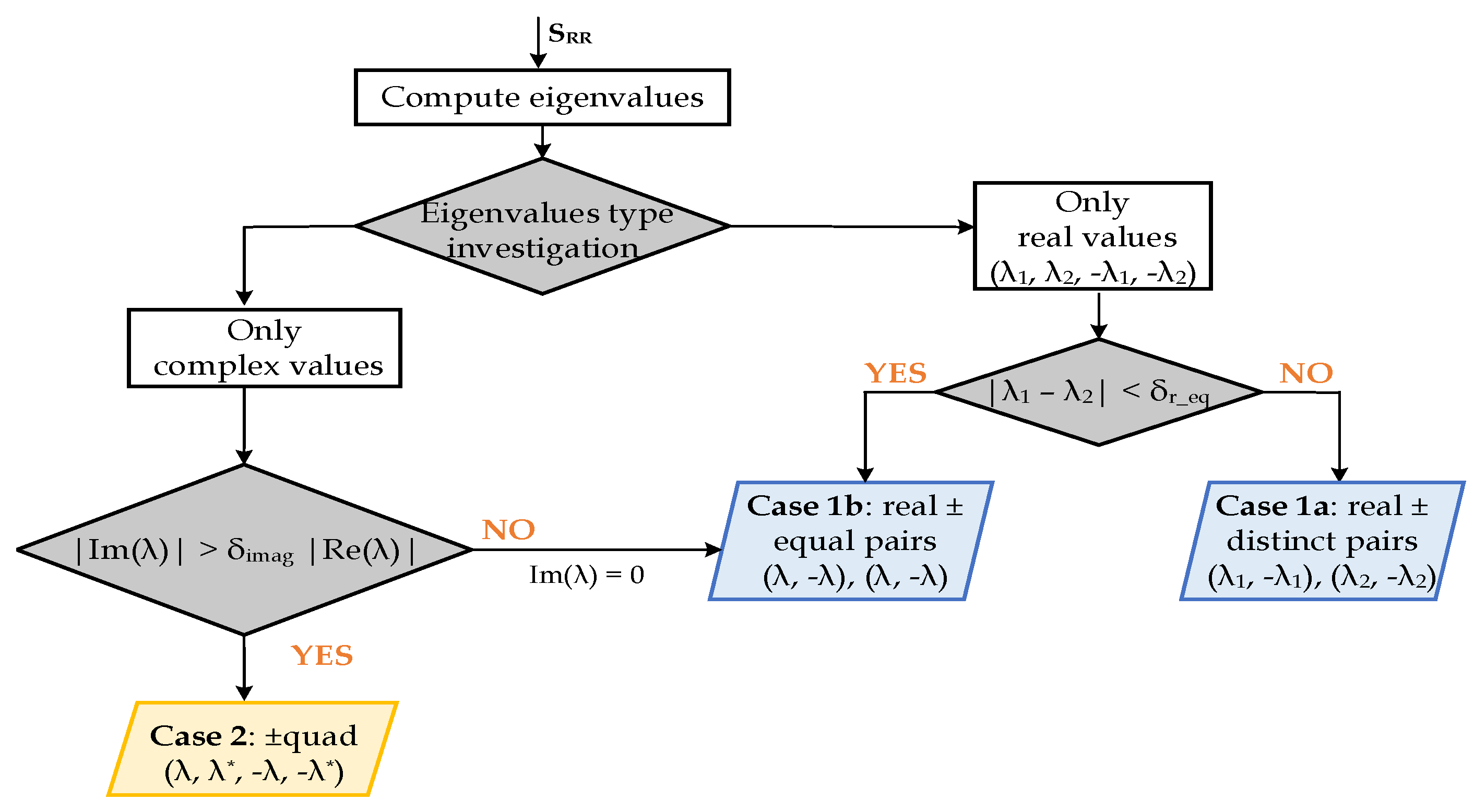
Figure 1 integrates the main steps for evaluating the RR eigenvalues considering both δ r _ e q and δ i m a g parameters.
In the remainder of this section, we perform a practical evaluation on real monostatic data, for choosing the tolerance parameter δ i m a g (between significance values of 1% or 5%).
Karnychev et al. [27,28] have introduced an invariant parameter for characterizing asymmetric scattering matrices, the polarization nonreciprocity factor (NRF). With the scattering matrix written in the HV basis: S = S h h S h v S v h S v v , the nonreciprocity factor will be:
ζ = 1 2 S v h S h v | | S | | F ,
where | | S | | F = | S h h | 2 + | S h v | 2 + | S v h | 2 + | S v v | 2 is the Euclidean norm.
The parameter is a complex number ζ = | ζ | · e j φ ζ C , with | ζ | [ 0 , 1 ] . The value is zero when the two cross-polar components are equal (i.e., reciprocal scattering matrices). As discussed, this is a case for which the RRSM eigen classification should return only real eigenvalues. For partially nonreciprocal objects, any values in the open interval | ζ | ( 0 , 1 ) can be expected.
Apart from the NRF value or the simple comparison of the difference/radio between HV and VH channels, statistical tests on the coherency matrix have also been proposed for assessing the reciprocity of general scattering matrices [29,30]. As discussed in the previous subsection, the types of eigenvalues obtained from decomposing the RR of a complex matrix may vary from real to purely imaginary if the matrix changes from symmetric to skew-symmetric. That is why we argue that, by investigating the RR eigenvalues, a new criterion for assessing the reciprocity of coherent scattering matrices can be obtained.
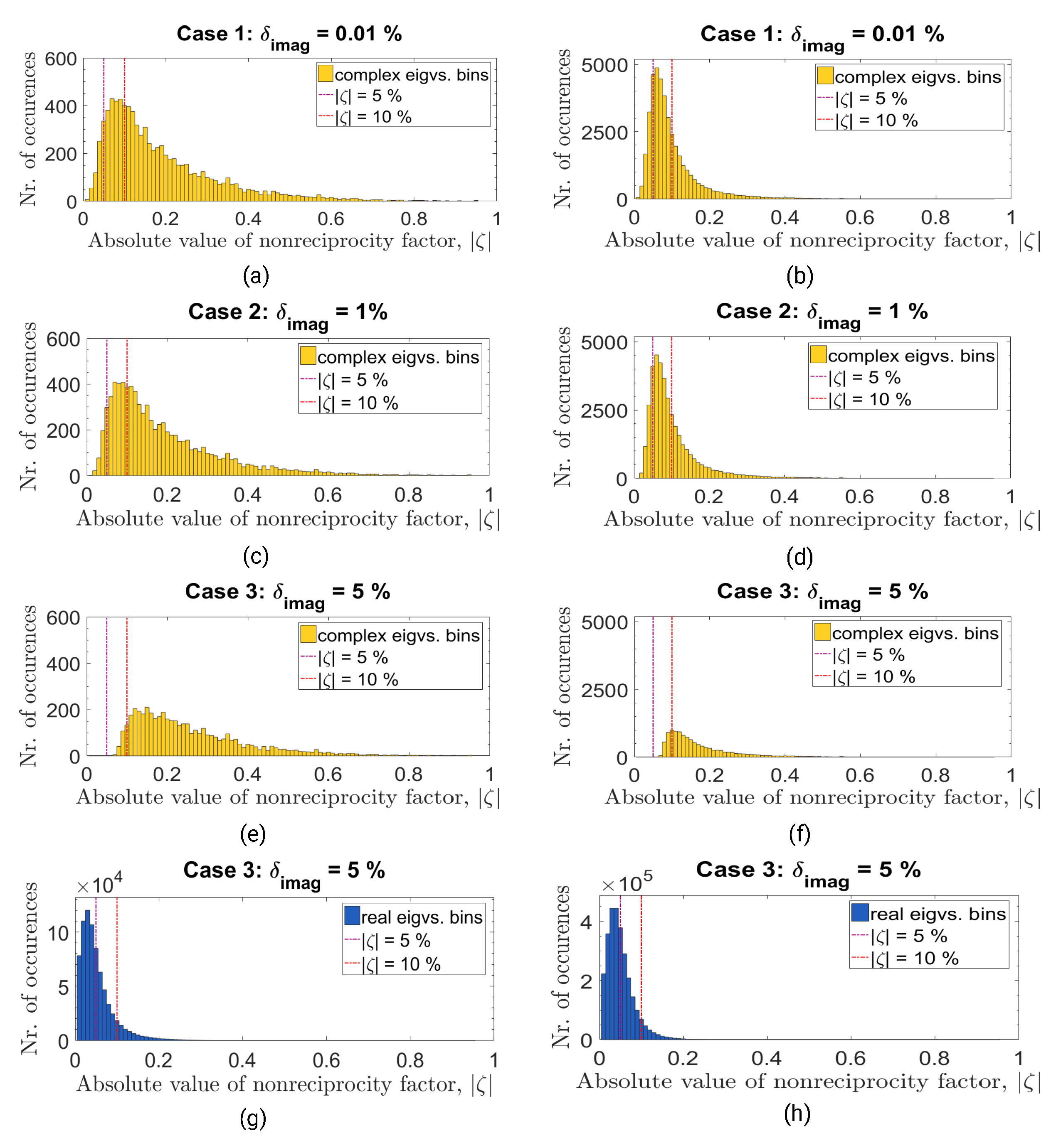
Table 3 and Figure 2 evaluate the differences in the distribution of RR eigenvalues classification of two Convair full-polarimetric monostatic scenes (details in Table 4) directly or by NRF investigation, respectively, when δ i m a g takes the values of 0.01 % , 1 % , 5 % . Speckle filtering or reciprocity equalization S h v n e w = S v h n e w = S h v + S v h 2 have not been applied to the two scenes; the investigation is performed directly on the original scattering matrices.
From Table 3, we observe that with both polarimetric datasets, by setting the value of δ i m a g to 1% the repartition of eigenvalues from complex to real, equal pairs changes with at most 0.1%. A more significant change, of ≈1% (migration from complex to real pairs) appears when increasing the δ i m a g threshold value to 5%. The percentages characterizing real, distinct eigenvalues pairs do not change in the table. This is because the variation of δ i m a g can influence only the distribution within the other two classes; e.g., complex eigenvalues pairs with a very small imaginary component may no longer pass the δ i m a g evaluation threshold, case in which we set to zero the imaginary part and the eigenvalues are evaluated now as real, equal pairs.
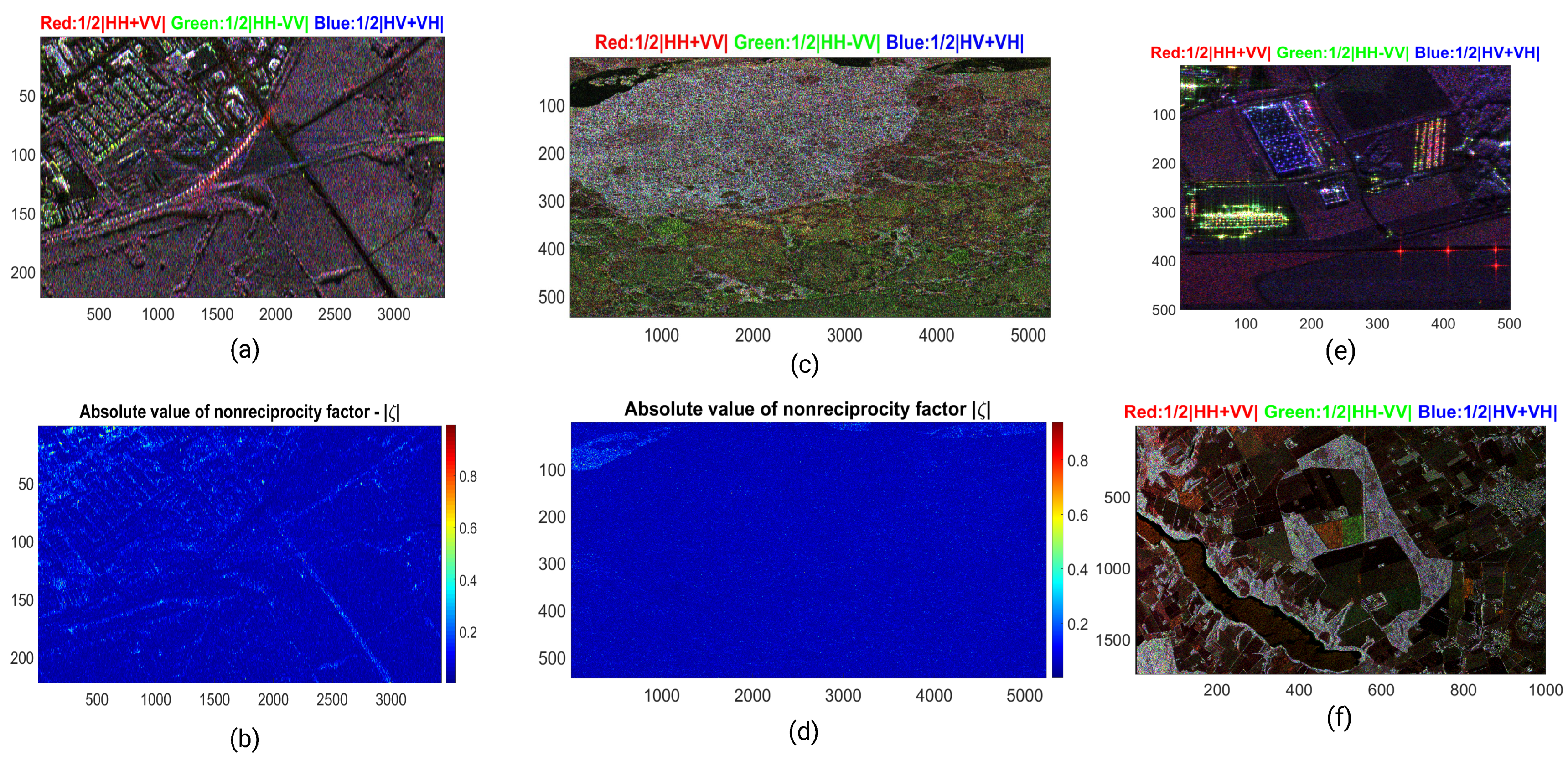
We evaluate now, with the help of results in Figure 2, the changes introduced by δ i m a g values modification, considering the nonreciprocity parameter. The histograms in yellow/blue display the distribution of scattering matrices, with respect to the absolute NRF parameter values, when their RRSM eigenvalues pairs are only of complex/real type. Changes are recorded for δ i m a g 0.01 % ; 1 % ; 5 % on first, second and third rows of Figure 2, respectively. On the graphs, the red and magenta dotted lines mark values of | ζ | = 0.05 ; 0.1 . Figure 3b,d display the absolute value of the NRF parameter for the monostatic Convair Ottawa and Convair Ice scenes. The Pauli color composite for the two images are shown in Figure 3a,c. The color coded images for the NRF parameters are rich in blue color which, as expected, corresponds to very low values for | ζ | .
For the blue histograms in Figure 2g,h, we observe that the majority of monostatic scattering matrices having RR real eigenvalues are characterized by a NRF below 0.1 (red line mark) if | ζ | = 5 % . For δ i m a g = 0.01 % and δ i m a g = 1 % , the yellow distributions reveal that a large number of scattering matrices (however, comparably lower than the peaks of the blue histogram) returning RR complex eigenvalues (but, of low values for the imaginary part) appear also for | ζ | values below 0.1 (i.e., nearly reciprocal matrices). On the third line of the yellow histograms (Figure 2e,f), the distributions change significant, with the decrease in the total number of eigenvalues classified as complex. The remaining RRSM not only present complex eigenvalues with an imaginary part of at least 5% (of its real part), but they also have a NRF factor of at least 0.05.
As the analyzed datasets are both monostatic, we see that the threshold value of δ i m a g can play a role in removing scattering points affected by noise (or other errors), points which may not be representative in the initial classification returned by the numerical analysis. That is why, hereafter we choose a level of significance δ i m a g = 5 % .

3. Practical Implementation and Testing

In this section, we concentrate on the RR scattering matrix eigenvalues testing with monostatic real SAR data and simulated data.

3.1. Real Monostatic Polarimetric Data

Two different real monostatic PolSAR datasets are selected. They have equal azimuth and range resolution values but were obtained by two airborne instruments working in different frequency bands (details in Table 4). Figure 3e,f display the Pauli color composite of the two scenes, over Brétigny and Foulum, respectively.
For each dataset, the RR eigenvalues classification is performed. To include all possible relations between (the absolute values) of the real and imaginary parts of each eigenvalue, five possible groups are considered: real (R), purely imaginary (I), complex with equal real and imaginary parts ( C e q R I ), complex but with a larger real part ( C G R ) and complex with a larger imaginary part ( C G I ). The former (real case) is itself divided, depending on whether the two ± pairs are distinct or equal.
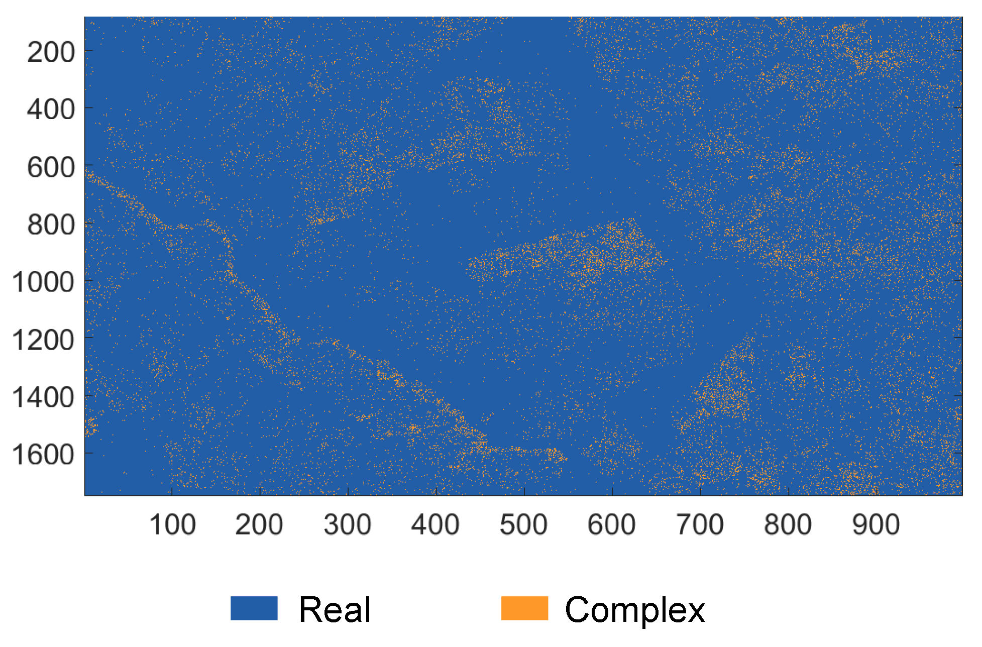
For both datasets, it is no surprise to verify that a striking percentage of the eigenvalues are of real type (Table 5). Moreover, the complex values generally have the real part larger than the imaginary one, with only a small percentage in the Foulum dataset displaying the opposite. For the Brétigny dataset, the small percentage of pixels classified with complex eigenvalues are at random positions, while in the Foulum image, some distinctive patterns/contours can be observed (Figure 4).

3.2. Simulated Monostatic Polarimetric Responses

Table 1 has presented a list of elementary scattering matrices for the canonical polarimetric objects, in linear horizontal (H) and vertical (V) basis. The letters (H/V) or numbers preceding the name of each scatterer signifies its orientation with respect to LOS. For some of the scatterers, simple analytical expressions can be found [31] for parametrizing the scattering matrices using in-plane rotations, around the radar LOS. However, when dealing with real imaging geometries, the scatterers will present quite diverse orientations, and we clearly expect that alongside the ideal scattering responses, more complex ones will appear.
In the current subsection, we propose to use a computational electromagnetic software (CES) in investigating the polarimetric responses of two elementary scatterers (a dihedral with square facets and a square plate, i.e., the canonical targets associated to double and single scattering mechanisms, respectively). Monostatic simulations have been performed using a computational electromagnetic software. The monostatic electric far-field response is computed with the help of the integral equation solver from the software tool. The solver performs a frequency domain analysis using a numerical method that divides the computational area of a scatterer into a certain number of meshing domains and then estimates the current distribution (and then the radiated fields) over each segment area. With the integral equation solver, we use the (default) surface-based meshing type.
A spherical coordinate system is used in the simulator for indicating the monostatic directions for transmission/reception and in computing the final backscattered E s electric field values,
E s = E φ s · φ ^ + E θ s · θ ^ ,
with φ ^ and θ ^ representing the versors in the spherical coordinates associated to the azimuth and elevation directions, respectively. Moreover, E φ s and E θ s are the projections of the far-field electric field along each of these directions.
The estimation of monostatic S matrices elements becomes a straightforward task, under known values of the incidence and scattered fields: E s = S · E i .
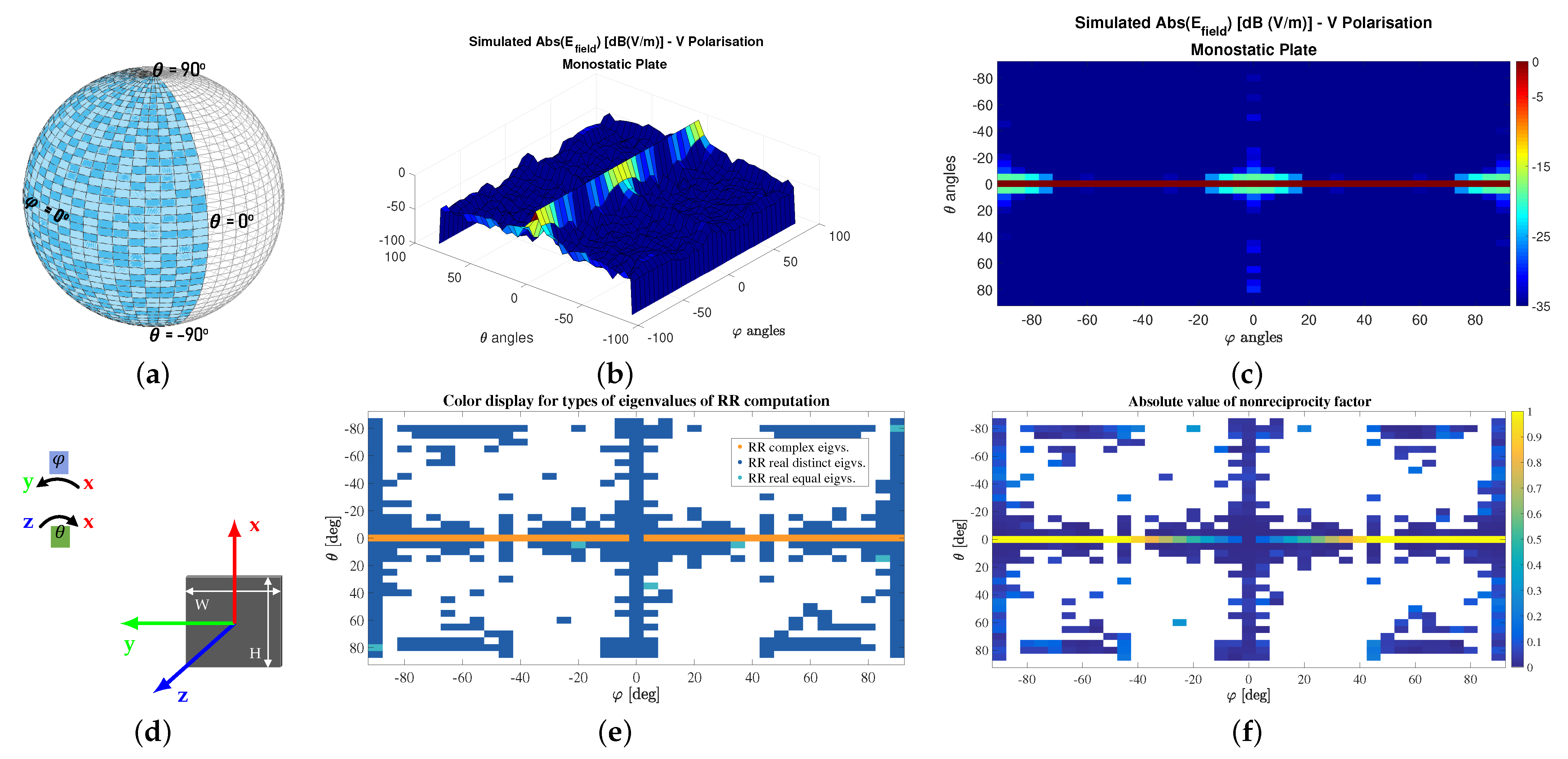
The simulated objects are large compared to the wavelength, modeled entirely from PEC (perfect electric conductor) materials. The representation of the two scatterers with respect to the local coordinate system can be examined in Figure 5d and Figure 6d. For the two scattering configurations, the electric field vector propagates along the Z direction, from positive to negative values. The spherical angular parameters ϕ and θ are defined in the XY and XZ planes, respectively. We consider the monostatic incidence/scattered directions within the angular intervals φ , θ [ 90 , 90 ] , with the direction defined by θ = 0 and ϕ = 0 aligned alongside the Z axis and representing the center of the coordinate system.
For the monostatic multi-directional responses of the plate and dihedral, we calculate the nonreciprocity factor and perform the eigenvalue decomposition of their algebraic RRs. Moreover, we compute two invariant polarimetric descriptors for analyzing the compliance of the simulated results to the well-known polarimetric phenomenology of odd and even bounce, which should characterize the response of the plate and dihedral.
The two descriptors are the coherent Cloude and Pottier α -angle, α C l o u d e [32]:
α C l o u d e = cos 1 2 | S h h + S v v | | | S | | F 1 ,
as well as the α -parameter of the Touzi TSVM decomposition α T S V M (used as α s for display reasons in the equation below), which appears in the modeling of the symmetric target scattering vector [5],
m e j Φ s 1 0 0 0 cos 2 Ψ sin 2 Ψ 0 sin 2 Ψ cos 2 Ψ cos α T S V M sin α T S V M · e j Φ α T S V M 0 .
For symmetric targets (in the polarimetric sense), the two parameters are expected to provide the same result [5].

3.2.1. Elementary Scatterer 1: Dihedral

We consider a 90 dihedral having square facets, with the joint line oriented along the Y axis, as in Figure 5d. To avoid any unwanted small-scale scattering effects, the dihedral is modeled as a large scatterer. Each facet has the dimension of 15 wavelengths. The central frequency of the signals used in the simulation belongs to the C-Band ( f 0 = 5.405 GHz). A small bandwidth of 20 MHz has been set. These parameters are widely in current Earth observation SAR missions, such as the Copernicus Sentinel-1 monostatic radars or the RADARSAT-2 constellation.
Figure 5c and Figure 6c display the simulated normalized electric field response for monostatic incidence/scattered directions spanning between θ [ 45 , 45 ] and φ [ 90 , 90 ] (illustration of angular interval in Figure 5a, which corresponds only to those directions illuminating the interior of the dihedral. The absolute value NRF for the scattering matrices computed for these directions, appears in Figure 5f. For almost all incidence/scattering positions, the estimated scattering matrices appear to verify reciprocity. However, around the θ = 0 line, NRF nonzero absolute values (below 0.4) appear associated with larger | φ | . By investigating also the colormap from Figure 5e, we observe that, for these positions, the type of the RR eigenvalues pairs varies from real-distinct (near normal incidence) to real-equal and then complex. In the entire image, the percentage distribution is that of 97.72% (real distinct eigenvalues pairs), 0.85% (real equal eigenvalues pairs) and 1.42% (complex pairs).
The problem of oriented dihedral scattering is one well known in polarimetry, and it has been shown that by increasing the orientation of a dihedral scatterer with respect to LOS, the power in the cross-channel components increases (for 45 the co-channel components S h h and S v v , become zero). For example, it is acknowledged that in urban environments, the effect of oriented dihedral is often misinterpreted by the model-based decomposition techniques as volume scattering [33], and efforts have been made in constructing models robust to such a fallacy [34,35]. With the current simulation (on line θ = 0 ), while the nonreciprocity factor appears to linearly increase even before φ = ± 45 , the RR eigenvalues change their type to complex just above this threshold (Figure 5e), from where the asymmetry of the scattering matrix is no longer negligible.
We compute at each investigated monostatic direction the values of the two angular parameters α C l o u d e and α T S V M (Figure 7). For this polarimetric descriptors, the theoretical value associated to the dihedral scatterer is that of 90 (with an acceptable statistical variation of ± 10 for real quad-pol data [36]). For all the monostatic directions investigated, Table 6 summarizes the percentage of angular values which fall within ranges of 10 , for the entire range of α values.
With respect to the θ direction (in combination with any φ value), variations of at most ± 20 do not produce significant changes in the evaluation of the scattering mechanism. Moreover, for more than 45% of the analyzed monostatic directions, the values of the two polarimetric descriptors remain within [ 70 , 90 ] . For observation directions on the upper/lower parts of each plate of the dihedral, near the free edges, the estimated α values suggest scattering mechanisms similar to that of a dipole ( 40 50 ). There are studies [26,37] that propose that any elementary scattering matrix can be written as a coherent sum of oriented and unoriented dipole scatterers with fixed spatial separations. For example, the dihedral scattering matrix is modeled by using two orthogonal dipoles (one H and one V) with a separation between them of λ 4 and the extreme cases of right and left rotated dihedrals can be written using dipoles with ± 45 orientation angles. Accordingly, we can suspect that dipoles with random orientations can be used for describing the phenomenology of randomly oriented dihedrals and one of such components becomes dominant, depending on orientation. A rapid check of the coneigenvalues returned at the investigated directions has not found matches of the results expected for H, V or 45 dihedrals (characterized by normalized { 1 , 0 } values, as in Table 2.
At θ = 0 direction, the inclination of the incidence wave (non-zero values of φ ) can be compensated by mapping to a preferential coordinate system in which the normal incidence on the scatterer is preserved (by performing a simple in-plane rotation of the dihedral). However, while a 2D rotation matrix describes only clockwise and counter-clockwise rotations, such a simple operation will not be sufficient for more complex model orientations (for compensating incidence/scattering directions of both non-zero θ and φ ).
It is also interesting to comment about the estimated values at the upper and lower θ limits, with | φ | ± 20 (near normal incidence). There, the reflection on the edges of the dihedral is dominant and therefore, the even bounce mechanism ( α 0 ) is perceived.
Finally, we observe that the estimation difference between the values of the two classical polarimetric parameters remains quite low only for directions near the scatterer’s center (Figure 7c), and overall the distribution of the identified scattering mechanisms remains the same (Table 6).

3.2.2. Elementary Scatterer 2: Square Plate

We now investigate a square plate having the same dimensions ( 15 λ ) as one single, square facet of the dihedral.
The scatterer is aligned in the XY plane with its center matching the center of the coordinate system, Figure 6d. For the simulated monostatic directions, we cover a much wider range, | θ | [0 , 90 ] (Figure 6a)-from normal incidence on the XY plane to reflection/refraction towards the edges of the plate.
We observe quite strong specular reflections near normal incidence on the plate’s facet (which is again off perfectly conducting material). However, because the absolute values of the simulated electric field are quite low for some of the monostatic directions (Figure 6c), we have decided to filter all responses from directions in which the scattered electric field (V polarization) is below −20 dB (normalized value). Very early radar experiments have shown that it is expected for oriented plates to present a smaller backscattered response [38]. The filtered directions are the ones in white for Figure 6e,f and Figure 8a,c. These have been disregarded in subsequent calculations (e.g., for percentages in Table 7).
Compared to the results obtained for the dihedral, the plate scatterer appears to be more sensitive for different variations in azimuth, around θ = 0 . The pattern can be observed by the rapidly increasing absolute values of the NRF parameter, which becomes equal to 1 with | φ | 45 (Figure 6e). However, as previously discussed, we observe the RR eigenvalues to change to complex type, from approximately | ζ | 0.5 . Similar to the dihedral case, we do not observe large changes of the NRF parameter (and consequently, for the eigenvalues type of the RRSMs) for other directions, characterized by non-zero θ and ϕ angles.
While it is reasonable to state that the oblique observations at these directions produce transformations of the scattering phenomenon, the overall reciprocity of the resulting scattering matrix appears not to be affected (e.g., very small values of the | ξ | parameter). For this reason, the two investigations performed in the paper (through the nonreciprocity factor and the RRSM eigenvalues classification) appear to be unable to offer more information about the effects present there.
With respect to the polarimetric descriptors, the even-bounce surface scattering mechanism (i.e., parameters values near 0 ± statistical fluctuations) is observed particularly for the case with θ [ 20 , 20 ] and φ [ 35 , 35 ] . Apart from the surface scattering mechanism characterizing these directions (and which presents the largest contribution in our 10 classification intervals, from Table 7, an important percentage is also represented by dipole scattering (large percentage of α values between [40 , 50 ] and [50 , 60 ]) and which imposes overall as dominant mechanism (appearing mostly for the angular intervals of very skewed incidence). While a surface unoriented in the LOS direction has a response which can be modeled by two orthogonal H and V dipoles with a separation of λ 2 [26], we argue that the great percentage of dihedral scattering observed for our monostatic skewed observations may appear as only one (possibly oriented) of those dipole components becomes dominant. However, further investigations will be necessary in this direction.
Whereas the values of the two estimated α parameters have again the same angular distribution, there are much larger differences for some of them in the angular range of observations (Figure 8c).

4. Final Discussion

4.1. Reciprocity and Nonreciprocity of the Scattering Matrix

In the previous section, we have performed an experimental investigation on both real and simulated monostatic data. A strong correlation exists between the values of the nonreciprocity parameter of a certain scattering matrix and the type of eigenvalues its RRSM form will present. For example, complex matrices having large NRF values certainly will exhibit eigenvalues of complex type when analyzing their RRSMs. However, the percentage of monostatic matrices exhibiting nonreciprocity in the real datasets investigated is (as expected) quite low and the real representation scattering matrices have predominantly real eigenvalues.
Nonetheless, with monostatic data, increasing the rotation around the LOS of elementary scatterers has proven to magnify the asymmetry between cross-channel components, which can be rapidly quantified through the nonreciprocity parameter or the eigenvalues classification of the RRSM. On the flip side, the shortcoming has also been identified: for those rotation effects which overall preserve the reciprocity property, neither the NRF nor the RRSM investigation are able to obtain new information. For such a case, polarimetric parameters as the monostatic coherent alpha angle may prove to be more reliable descriptors: investigations on simulated data using a computational electromagnetic software have shown that dihedral and plate scatterers with skewed or side illumination present scattering mechanisms similar to those of dipoles. Approaches to better quantify such situations may form the core of future works. Indeed, there is already a great piece of literature devoted to the study and estimation of the polarimetric orientation angle (POA), with the parameter being defined as the angle of rotation around LOS [39] and used for compensating the asymmetry introduced by such a rotation directly on the scattering matrix (e.g., used with the TSVM method) or on the coherency/covariance matrix (i.e., mainly a pre-processing step for current model-based decompositions).
The experiments with the simulated scatterers in Section 3.2 have shown an increase in the asymmetry of the scattering matrix for some incidence directions ( θ = 0 , φ [ 90 , 90 ] ), while for other directions the asymmetry assumption of the response matrix has not proven itself as a distinctive mark for the underling skewed incidence/scattered configurations. Further investigations are needed for addressing such aspects.
Apart from certain LOS orientation effects, it is shown by the literature that a monostatic scattering response will no longer display reciprocity due to strong nonuniform behaviors of the propagation medium.
On a distinct note, there is nowadays, in the radar community, an increased interest in deploying systems with distributed geometries: quasi-monostatic, bistatic or multistatic. Under full-polarimetric diversity, the backscattering response of such systems will no longer be compliant with the reciprocity assumption.

4.2. Conclusions

The new real representation framework for solving the conjugate similarity with the polarimetric scattering matrix, under BSA, has been presented. This allowed to explore the space generated by the coneigenvalues at its full extent, being reciprocal/nonreciprocal, or real/complex-valued.
By means of investigating the imaginary part of the coneigenvalues, we have challenged the reciprocity condition imposed with the non-negative factorization of the Hermitian Graves matrix.
Results obtained with both real SAR and simulated monostatic polarimetric data has revealed that complex coneigenvalues can be present. As expected, they appear with a very low probability, below 5% in all cases.
Further work will address in-depth analysis of the coneigenvectors corresponding to nonreciprocal scattering matrices. For the time being, the current framework is restricted to coherent applications. Investigations towards an incoherent target decomposition model will be considered.

Author Contributions

Conceptualization, M.C. and G.V.; methodology, M.C. and G.V.; software, M.C. and A.A.; validation, M.C., G.V. and A.A.; writing—original draft preparation, M.C. and G.V.; writing—review and editing, G.V.; visualization, M.C. and A.A.; supervision, G.V., M.G and S.C.; project administration, G.V. and M.G.; funding acquisition, M.G. and G.V. All authors have read and agreed to the published version of the manuscript.

Funding

This research was funded under a PhD grant from the French Ministry of Higher Education and Research.

Data Availability Statement

Not applicable.

Acknowledgments

The authors would like to thank Fabien Ndagijimana from the Grenoble Institute of Technology, Grenoble, France, for providing access to the CST Microwave Studio software.

Conflicts of Interest

The authors declare no conflict of interest.

Abbreviations

BSABackscattering Alignment
CESComputational Electromagnetic Software
CDTCoherent Decomposition Techniques
EMISARElectroMagnetic Institute Synthetic Aperture Radar
HHorizontal Polarization
LOSLine of Sight
NRFNonreciprocity Factor
ONERAThe French Aerospace Lab
Office National d’Etudes et de Recherches Aérospatiales
PECPerfect Electrical Conductor
POAPolarimetric Orientation Angle
PolSARPolarimetric Synthetic Aperture Radar
RAMSESRadar Aéroporté Multi-spectral d’Etude des Signatures
RRReal Representation
RRSMReal Representation Scattering Matrix
SARSynthetic Aperture Radar
SMScattering Matrix
TSVMTarget Scattering Vector Model
TUDTechnical University of Denmark
VVertical Polarization

References

  1. Krogager, E. Decomposition of the radar target scattering matrix with application to high resolution target imaging. In Proceedings of the National Telesystems Conference, Atlanta, GE, USA, 16–27 March 1991; pp. 77–82. [Google Scholar] [CrossRef]
  2. Huynen, J.R. Phenomenological Theory of Radar Targets. Ph.D. Thesis, Tech. Univ. Delft, Delft, The Netherlands, 1970. [Google Scholar]
  3. Cameron, W.L.; Leung, L.K. Feature motivated polarization scattering matrix decomposition. In Proceedings of the IEEE International Conference on Radar, Arlington, VT, USA, 7–10 May 1990; pp. 549–557. [Google Scholar]
  4. Cameron, W.L.; Rais, H. Derivation of a Signed Cameron Decomposition Asymmetry Parameter and Relationship of Cameron to Huynen Decomposition Parameters. IEEE Trans. Geosci. Remote. Sens. 2011, 49, 1677–1688. [Google Scholar] [CrossRef]
  5. Touzi, R. Target Scattering Decomposition in Term of Roll-Invariant Target Parameters. IEEE Trans. Geosci. Remote. Sens. 2007, 45, 73–84. [Google Scholar] [CrossRef]
  6. Carrea, L.; Wanielik, G. Polarimetric SAR processing using the polar decomposition of the scattering matrix. In Proceedings of the IEEE International Geoscience and Remote Sensing Symposium (IGARSS), Sydney, Ausralia, 9–13 July 2001; Volume 1, pp. 363–365. [Google Scholar] [CrossRef]
  7. Li, H.; Chen, J.; Li, Q.; Wu, G.; Chen, J. Mitigation of Reflection Symmetry Assumption and Negative Power Problems for the Model-Based Decomposition. IEEE Trans. Geosci. Remote Sens. 2016, 54, 7261–7271. [Google Scholar] [CrossRef]
  8. Lee, J.S.; Pottier, E. Polarimetric Radar Imaging: From Basics to Applications; CRC Press-Taylor and Francisc Group: Boca Raton, FL, USA, 2009. [Google Scholar]
  9. Hajnsek, I.; Desnos, Y.L. Polarimetric Synthetic Aperture Radar: Principles and Application; Springer: Berlin, Germany, 2020. [Google Scholar]
  10. Ikramov, K.D. A note on complex matrices that are unitarily congruent to real matrices. Linear Algebra Its Appl. 2010, 433, 838–842. [Google Scholar] [CrossRef]
  11. Hong, Y.; Horn, R.A. A characterization of unitary congruence. Linear Multilinear Algebra 1989, 25, 105–119. [Google Scholar] [CrossRef]
  12. Lüneburg, E.; Morisaki, J.; Boerner, W.M. On the forward scatter alignment and the backscatter alignment conventions of bistatic radar polarimetry. In Proceedings of the ISAP, 24–27 March 2004; Volume 1, pp. 1273–1276. [Google Scholar]
  13. Bebbington, D.; Carrea, L. On Mathematical and Physical Principles of Transformations of the Coherent Radar Backscatter Matrix. IEEE Trans. Geosci. Remote. Sens. 2012, 50, 4657–4669. [Google Scholar] [CrossRef]
  14. Wu, A.G.; Zhang, Y. Complex Conjugate Matrix Equations for Systems and Control; Springer: Berlin, Germany, 2017. [Google Scholar]
  15. Ling, S.; Jiang, T. New Method for General Kennaugh’s Pseudoeigenvalue Equation in Radar Polarimetry. Front. Math. China 2012, 7, 85–95. [Google Scholar] [CrossRef]
  16. Jiang, T.; Cheng, X.; Chen, L. An Algebraic Relation Between Consimilarity and Similarity of Complex Matrices and its Applications. J. Phys. Math. Gen. 2006, 39, 9215–9222. [Google Scholar] [CrossRef]
  17. Hellings, C.; Utschick, W. Block-Skew-Circulant Matrices in Complex-Valued Signal Processing. IEEE Trans. Signal Process. 2015, 63, 2093–2107. [Google Scholar] [CrossRef]
  18. Wu, A.G.; Wang, H.Z. A real representation of complex polynomial matrices in the framework of conjugate product. Int. J. Comput. Math. 2019, 96, 1567–1575. [Google Scholar] [CrossRef]
  19. Jiang, T.; Ling, S. Algebraic Methods for Condiagonalization Under Consimilarity of Quaternion Matrices in Quaternion Quantum Mechanics. Adv. Appl. Clifford Algebr. 2013, 23, 405–415. [Google Scholar] [CrossRef]
  20. Kösal, H.H.; Tosun, M. Universal similarity factorization equalities for commutative quaternions and their matrices. Linear Multilinear Algebra 2019, 67, 926–938. [Google Scholar] [CrossRef]
  21. Hellings, C.; Utschick, W. Two different real representations of complex matrices for describing widely linear systems. In Proceedings of the International Symposium on Wireless Communication Systems, Brussels, Belgium, 25–28 August 2015; pp. 641–645. [Google Scholar] [CrossRef]
  22. Jiang, T.; Wei, M. On the Reduction of a Complex Matrix to Triangular or Diagonal by Consimilarity. Numer. Math. Engl. Ser. 2006, 15, 107. [Google Scholar]
  23. Graves, C. Radar Polarization Power Scattering Matrix. Proc. IRE 1956, 44, 248–252. [Google Scholar] [CrossRef]
  24. Horn, R.; Johnson, C. Matrix Analysis, 2nd ed.; Cambridge University Press: Cambridge, UK, 2013. [Google Scholar]
  25. Ciuca, M.; Vasile, G.; Gay, M.; Anghel, A.; Ciochina, S. Polarimetric Analysis using the Algebraic Real Representation of the Scattering Matrix. In Proceedings of the International Geoscience and Remote Sensing Symposium (IGARSS), Brussels, Belgium, 11–16 July 2021; pp. 499–502. [Google Scholar] [CrossRef]
  26. Singh, G.; Yamaguchi, Y. Model-Based Six-Component Scattering Matrix Power Decomposition. IEEE Trans. Geosci. Remote. Sens. 2018, 56, 5687–5704. [Google Scholar] [CrossRef]
  27. Karnychev, V.; Khlusov, V.A.; Ligthart, L.P.; Sharygin, G. Algorithms for estimating the complete group of polarization invariants of the scattering matrix (SM) based on measuring all SM elements. IEEE Trans. Geosci. Remote Sens. 2004, 42, 529–539. [Google Scholar] [CrossRef]
  28. Karnychev, V.; Ligthart, L.; Khlusov, V.; Sharygin, G. Determination of polarization invariants of asymmetric scattering matrix. In Proceedings of the International Conference on Microwaves, Radar and Wireless Communications, 20–22 May 2002; Volume 2, pp. 572–575. [Google Scholar] [CrossRef]
  29. Aubry, A.; Carotenuto, V.; De Maio, A.; Pallotta, L. Assessing Reciprocity in Polarimetric SAR Data. IEEE Geosci. Remote Sens. Lett. 2020, 17, 87–91. [Google Scholar] [CrossRef]
  30. Pallotta, L. Reciprocity Evaluation in Heterogeneous Polarimetric SAR Images. IEEE Geosci. Remote Sens. Lett. 2020, 1–5. [Google Scholar] [CrossRef]
  31. Dallmann, T. Polarimetric Radar Cross-Section Imaging. Ph.D. Thesis, RWTH Aachen University, Aachen, Germany, 2017. [Google Scholar]
  32. Cloude, S. Polarisation: Applications in Remote Sensing; Oxford University Press: Oxford, UK, 2009. [Google Scholar]
  33. Delgado Blasco, J.M.; Fitrzyk, M.; Patruno, J.; Ruiz-Armenteros, A.M.; Marconcini, M. Effects on the Double Bounce Detection in Urban Areas Based on SAR Polarimetric Characteristics. Remote Sens. 2020, 12, 1187–1209. [Google Scholar] [CrossRef]
  34. Xiang, D.; Ban, Y.; Su, Y. The cross-scattering component of polarimetric SAR in urban areas and its application to model-based scattering decomposition. Int. J. Remote Sens. 2016, 37, 3729–3752. [Google Scholar] [CrossRef]
  35. Atwood, D.K.; Thirion-Lefevre, L. Polarimetric Phase and Implications for Urban Classification. IEEE Trans. Geosci. Remote Sens. 2018, 56, 1278–1289. [Google Scholar] [CrossRef]
  36. Nord, M.; Ainsworth, T.; Lee, J.S.; Stacy, N. Comparison of Compact Polarimetric Synthetic Aperture Radar Modes. IEEE Trans. Geosci. Remote Sens. 2009, 47, 174–188. [Google Scholar] [CrossRef]
  37. Wang, Y.; Yu, W.; Hou, W. Five-Component Decomposition Methods of Polarimetric SAR and Polarimetric SAR Interferometry Using Coupling Scattering Mechanisms. IEEE J. Sel. Topics Appl. Earth Observ. Remote Sens. 2021, 14, 6662–6676. [Google Scholar] [CrossRef]
  38. Lahaie, I.; Sengupta, D. Scattering of electromagnetic waves by a slowly rotating rectangular metal plate. IEEE Trans. Antennas Propag. 1979, 27, 40–46. [Google Scholar] [CrossRef]
  39. Lee, J.S.; Ainsworth, T.L.; Wang, Y. Polarization Orientation Angle and Polarimetric SAR Scattering Characteristics of Steep Terrain. IEEE Trans. Geosci. Remote Sens. 2018, 56, 7272–7281. [Google Scholar] [CrossRef]
Figure 1. Flowchart for tolerance parameters testing.
Remotesensing 15 01037 g001
Figure 2. Convair Ottawa results (left); Convair Ice results (right); (a,c,e) Changes in the distribution of NRF absolute values for the RRSMs returning complex eigenvalues (yellow color), introduced by varying δ i m a g -Convair Ottawa data. (b,d,f) Same as with (a,c,e), but for Convair Ice data. (g) Distribution of NRF absolute values for RRSMs returning real eigenvalues (blue color), when δ i m a g = 5%-Convair Ottawa data. (h) Same as (g), for Convair Ice data.
Remotesensing 15 01037 g002
Figure 3. Pauli color composites for polarimetric data: (a) Convair Ottawa. (c) Convair Ice. (e) Ramses Brétigny. (f) Emisar Foulum. Absolute value of NRF parameter: (b) Convair Ottawa. (d) Convair Ice.
Remotesensing 15 01037 g003
Figure 4. Colormap displaying positions of real and complex RR eigenvalues (Emisar Foulum).
Remotesensing 15 01037 g004
Figure 5. 90 Dihedral. (a) Range of incidence/scattered spherical positions for the monostatic simulations. Normalized absolute value of simulated scattered electric far-field E f i e l d s [dB(V/m)]: (b) Vertical polarization, 3D. (c) Vertical polarization, 2D. (d) Dihedral representation in the general coordinate system. (e) Colormap display for RR eigenvalues classification of the dihedral’s monostatic response, for observation directions in the investigated range. (f) Modulus of the nonreciprocity factor for the dihedral’s monostatic response for observation directions in the investigated range.
Remotesensing 15 01037 g005
Figure 6. Square plate. (a) Range of incidence/scattered spherical positions for the monostatic simulations. (b) Normalized absolute value of simulated scattered electric far-field E f i e l d s [dB(V/m)]: (b) Vertical polarization, 3D. (c) Vertical polarization, 2D. (d) Square plate representation in the general coordinate system. (e) Colormap display for RR eigenvalues classification of the plate’s monostatic response for a selection of observation directions in the investigated range. (f) Modulus of the nonreciprocity factor for the plate’s monostatic response for a selection of observation directions.
Remotesensing 15 01037 g006
Figure 7. 90 Dihedral. (a) Estimation of α C l o u d e parameter for the dihedral’s response for all observation directions in the investigated range. (b) Estimation of α T S V M parameter for the dihedral’s response for all observation directions in the investigated range. (c) Absolute difference between results from (a,b).
Remotesensing 15 01037 g007
Figure 8. Square plate. (a) Estimation of α C l o u d e parameter for the plate’s response for a selection of observation directions. (b) Estimation of α T S V M parameter for the plate’s response for a selection of observation directions. (c) Absolute difference between results from (a,b).
Remotesensing 15 01037 g008
Table 1. Monostatic scattering matrices of elementary targets in HV basis.
H dipole 45 dipole V dipole
1 0 0 0 1 2 · 1 1 1 1 0 0 0 1
H dihedral 45 dihedral V dihedral
1 0 0 1 0 1 1 0 1 0 0 1
H quarter-wave 45 quarter wave V quarter-wave
1 0 0 i 1 i 2 · 1 1 1 1 i 0 0 1
sphere/platecenter helixright helix
1 0 0 1 1 2 · 1 i i 1 1 2 · 1 i i 1
Table 2. Coneigenvalues and coneigenvectors determined through the RR method for some of the elementary scattering matrices.
ScatterersConeigenvs. ξ 1 , ξ 2 Coneigenvectors
sphere/plate 1 , 1 x 1 = 1 , 0 T x 2 = 0 , 1 T
H dipole 1 , 0 x 1 = 1 , 0 T x 2 = 0 , 1 T
45 dipole 1 , 0 x 1 = 1 2 , 1 2 T x 2 = x 1
V dipole 1 , 0 x 1 = 0 , 1 T x 2 = 1 , 0 T
H dihedral 1 , 1 x 1 = 1 2 · 1 , i T x 2 = x 1 *
V dihedral 1 , 1 x 1 = 0 , 0 T x 2 = 0 , 1 T
H quarter-wave 1 , 1 x 1 = 1 2 · 1 , 1 2 + i 1 2 T x 2 = x 1 *
V quarter-wave 1 , 1 x 1 = 1 2 · 1 2 i 1 2 , 1 T x 2 = x 1 *
Table 3. Variations in the distribution of RRSM eigenvalues type, with changes in the values of δ i m a g , for two monostatic real PolSAR dataset (Convair Ottawa and Convair Ice).
Real Eigvs. Pairs [%]Complex Real Eigvs. Pairs [%]Complex
δ imag DistinctEqualPairs [%] δ imag DistinctEqualPairs [%]
CONV. Ottawa CONV. Ice
0.01%98.9030.0001.09 98.5580.0001.440
1%98.9030.0451.05 98.5580.1041.340
5%98.9030.4830.61 98.5581.0370.400
Table 4. Monostatic full-polarimetric datasets used in the paper.
Dataset NameAcquisition System (Institution)Type, BandResolution (rg. × az.) [m]Size (Rows × Columns)
Convair IceCONVAIR (Environment Canada)airborne, C4 × 0.4544 × 5238
Convair OttawaCONVAIR (Environment Canada)airborne, C4 × 0.4222 × 3429
Ramses BrétignyRAMSES (ONERA)airborne, X1.5 × 1.5501 × 501
Emisar FoulumEMISAR (TUD, Denmark)airborne, C2 × 21750 × 1000
Table 5. Classification of RR eigenvalues for two real datasets.
DatasetReal Pairs (R) [%]Complex Pairs [%]
DistinctEqual C eqRI C GR C GI
RAMSES Brétigny99.380.3600.260
EMISAR Foulum95.610.703.630.06
Table 6. 90 Dihedral. Percentage distribution of estimated values for the angular polarimetric descriptors in intervals of 10 deg., between [0, 90] deg. (for all observation directions in the investigated range).
ParameterAngular Intervals for Values of Polarimetric Descriptor: [Upper limit , Lower limit ) [deg.]
90–8080–7070–6060–5050–4040–3030–2020–1010–0
α C l o u d e 28.7%18.2%12.8%9.8%15.1%8.53%4.03%1.42%1.42%
α T S V M 28.7%17.5%11.8%9.8%12.95%11.7%4.7%1.42%1.42%
Table 7. Square plate. Percentage distribution of estimated values for the angular polarimetric descriptors, in intervals of 10 deg., between [0, 90] deg., for the selection of monostatic observation directions.
ParameterAngular Intervals for Values of Polarimetric Descriptor: [Upper limit , Lower limit ) [deg.]
90–8080–7070–6060–5050–4040–3030–2020–1010–0
α C l o u d e 2.32%3.48%6.72%13.0%18.8%9.28%8.12%16%22.27%
α T S V M 2.08%3.71%5.9%13.45%17.86%8.32%7.65%13.9%27.13%
Disclaimer/Publisher’s Note: The statements, opinions and data contained in all publications are solely those of the individual author(s) and contributor(s) and not of MDPI and/or the editor(s). MDPI and/or the editor(s) disclaim responsibility for any injury to people or property resulting from any ideas, methods, instructions or products referred to in the content.