
An In-Flight Alignment Method for Global Positioning System-Assisted Low Cost Strapdown Inertial Navigation System in Flight Body with Short-Endurance and High-Speed Rotation

 , and
, and
Abstract
1. Introduction
2. Construction of Multi-Vector Alignment Model on Lie Group
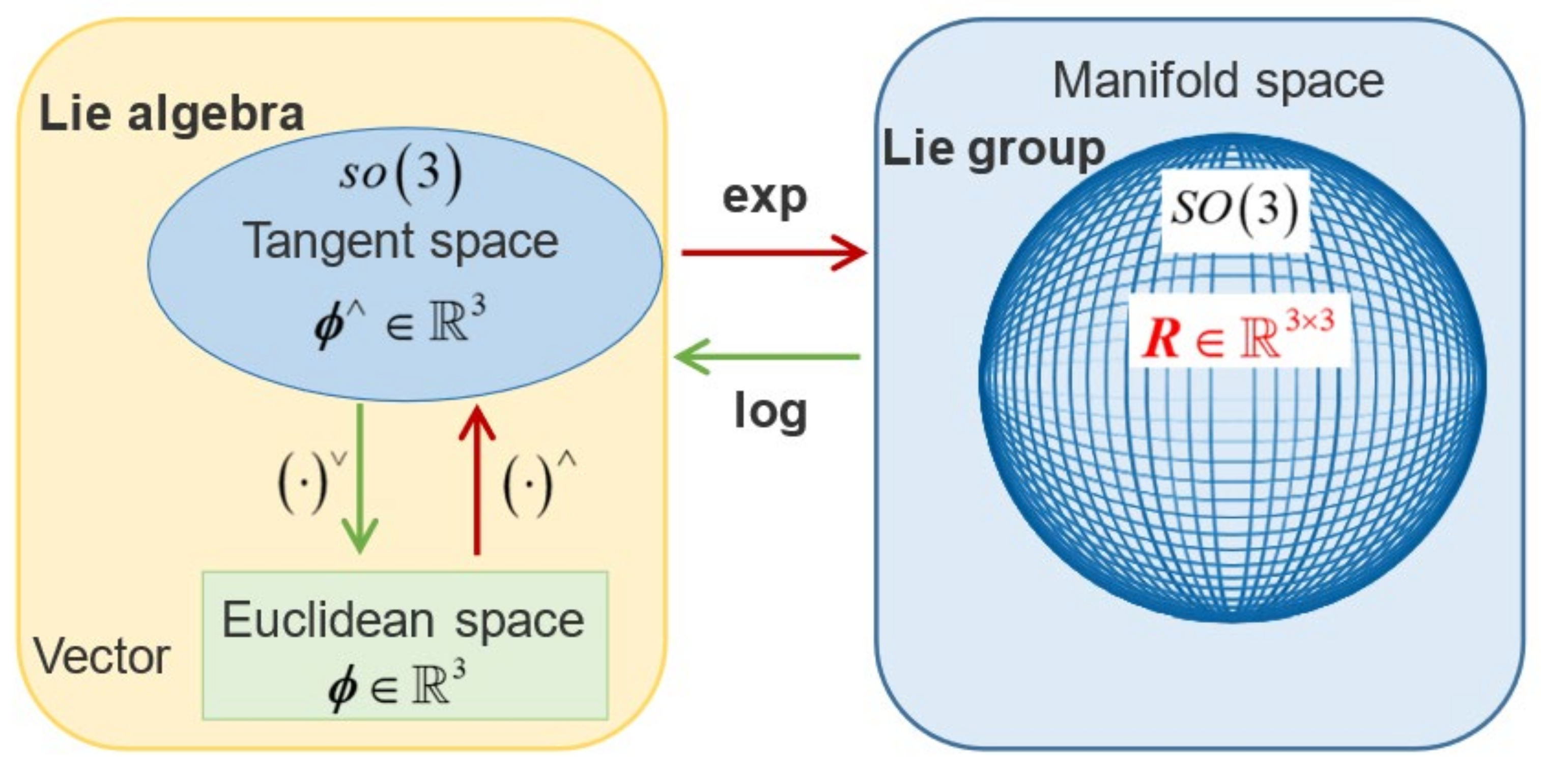
2.1. Mathematical Description of the Lie Group
2.2. Alignment Principle of Multi-Vector Attitude Determination on Lie Group
3. Improved UKF Based on Lie Group
3.1. Error Analysis
3.2. Improved UKF Modeling on Lie Group
- 1)
- Initialization
- 2)
- Time Update
- (a)
- Predicting the model value at k + 1 time:
| Algorithm 1: Calculation of on . |
| Input: Set of rotations in |
| 1. |
| 2. |
| 3. |
| 4. return |
- (b)
- Calculating the covariance matrix
- (c)
- Combining vectors and into vector . The predicted covariance is then calculated as:
- 3)
- Measurement Update
- 4)
- Calculation of Auto-Covariance Matrix and Cross-Covariance Matrix
- 5)
- Filtering Update
- (a)
- Calculating filter gain matrix:
- (b)
- Correcting the state prediction:
- (c)
- Updating the covariance of the system:
4. Simulation and Experimental Results
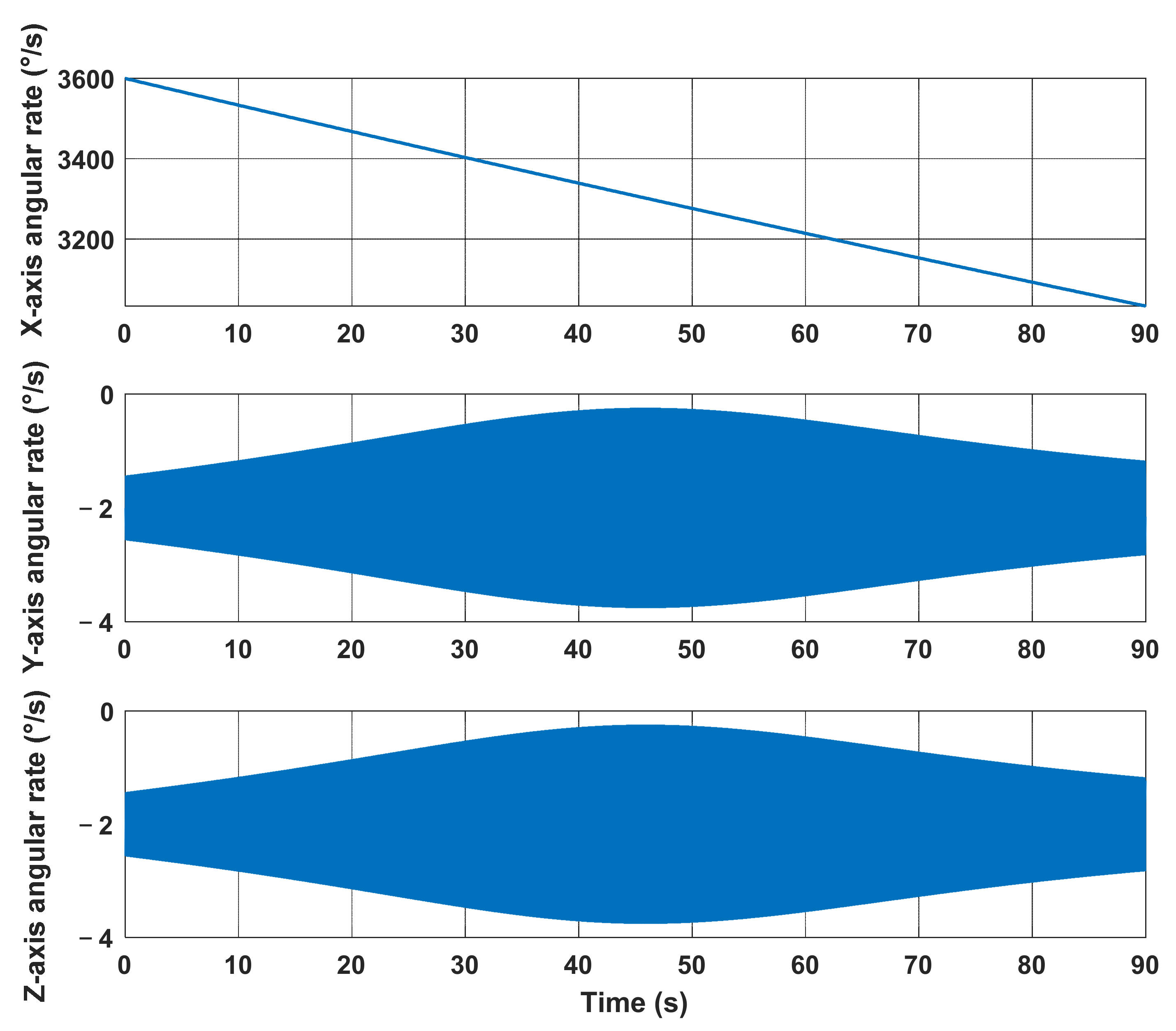
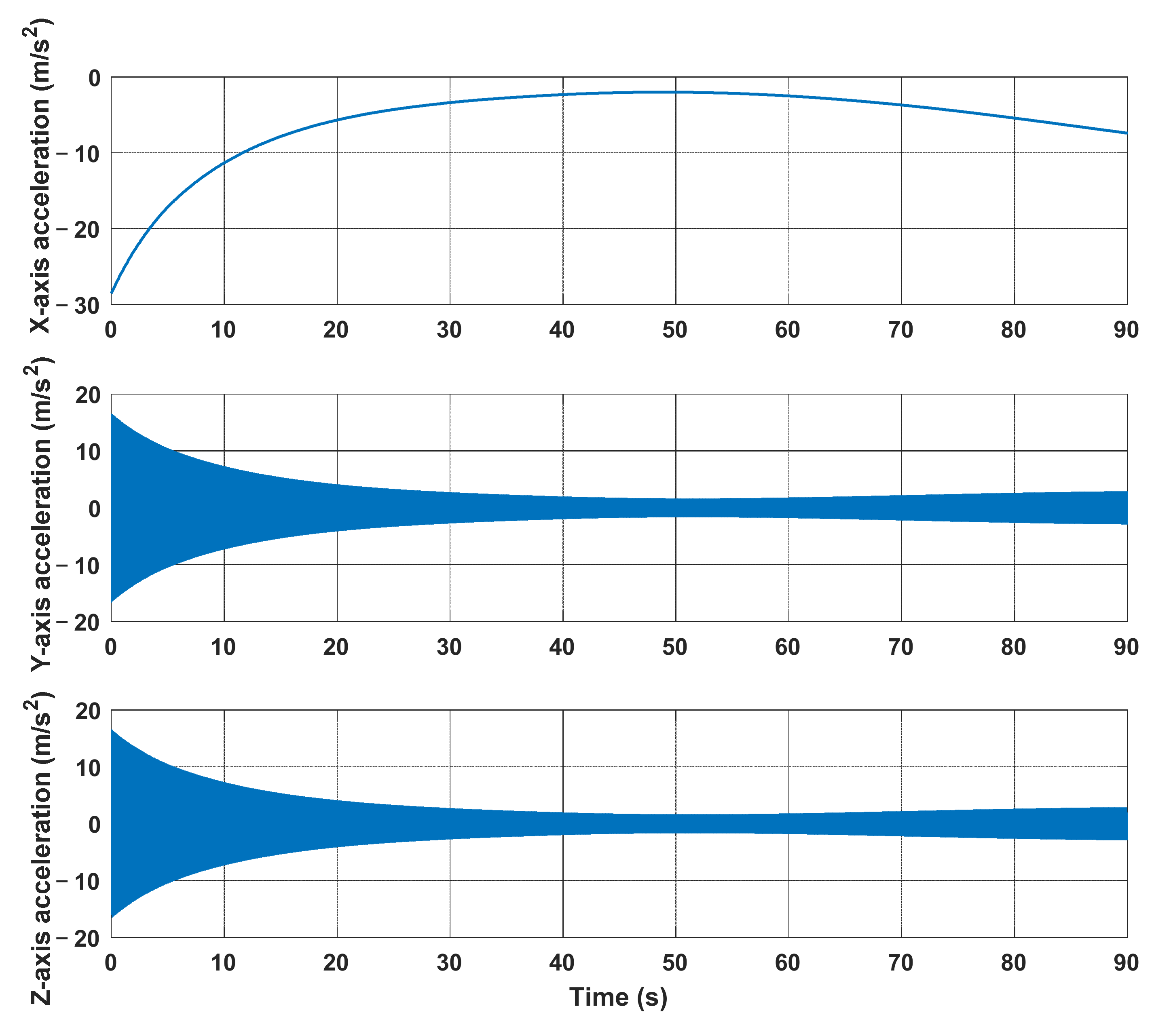
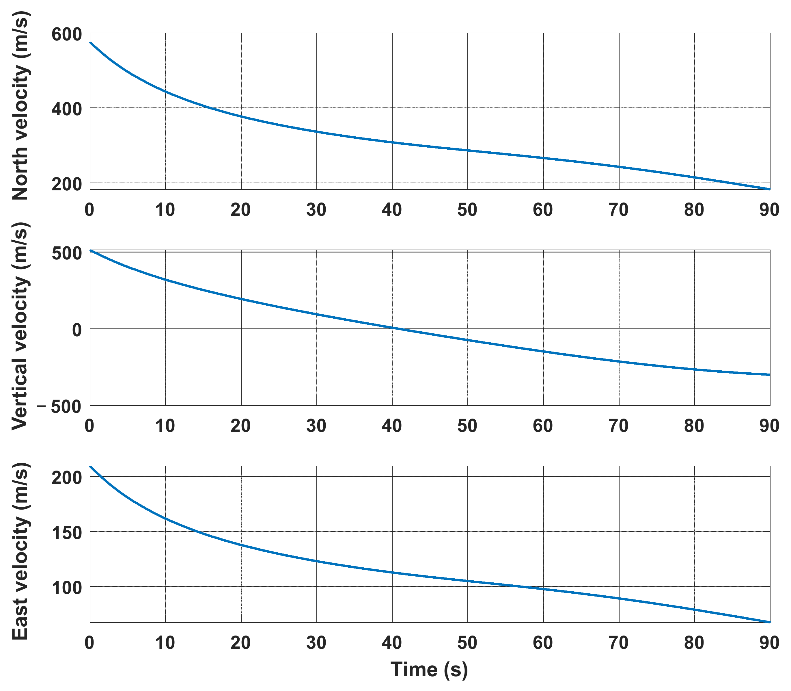
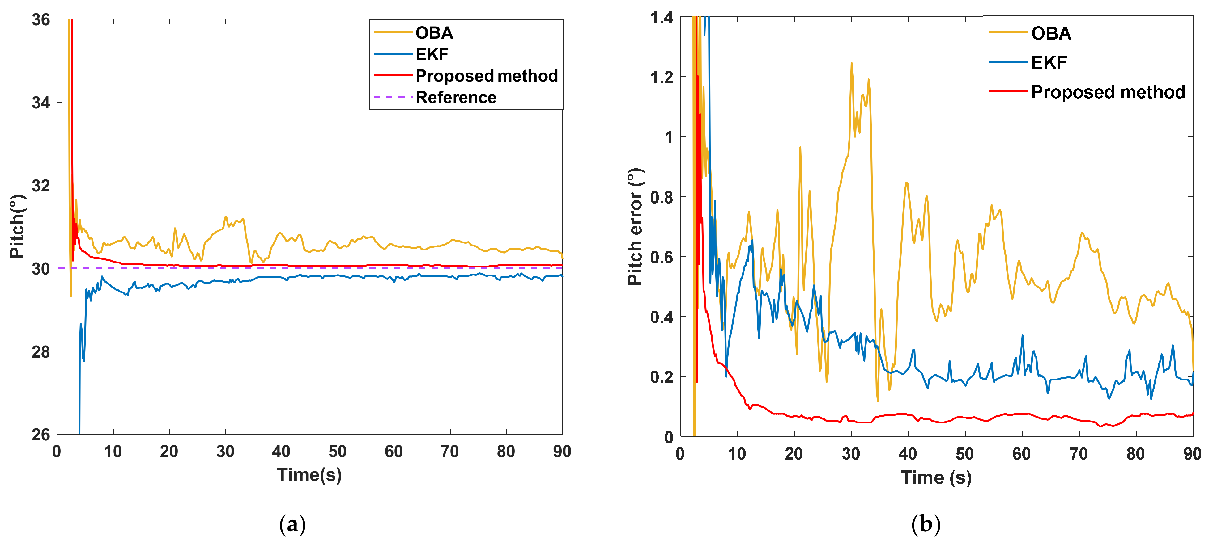
4.1. Simulation Results
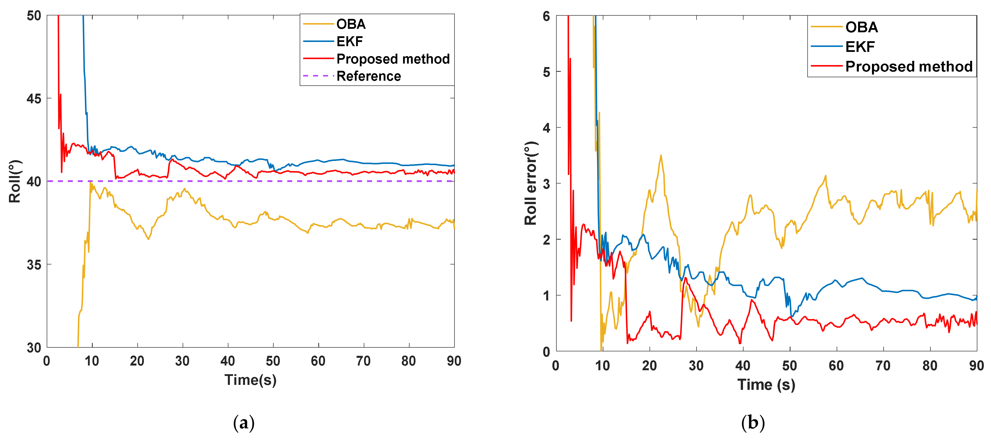
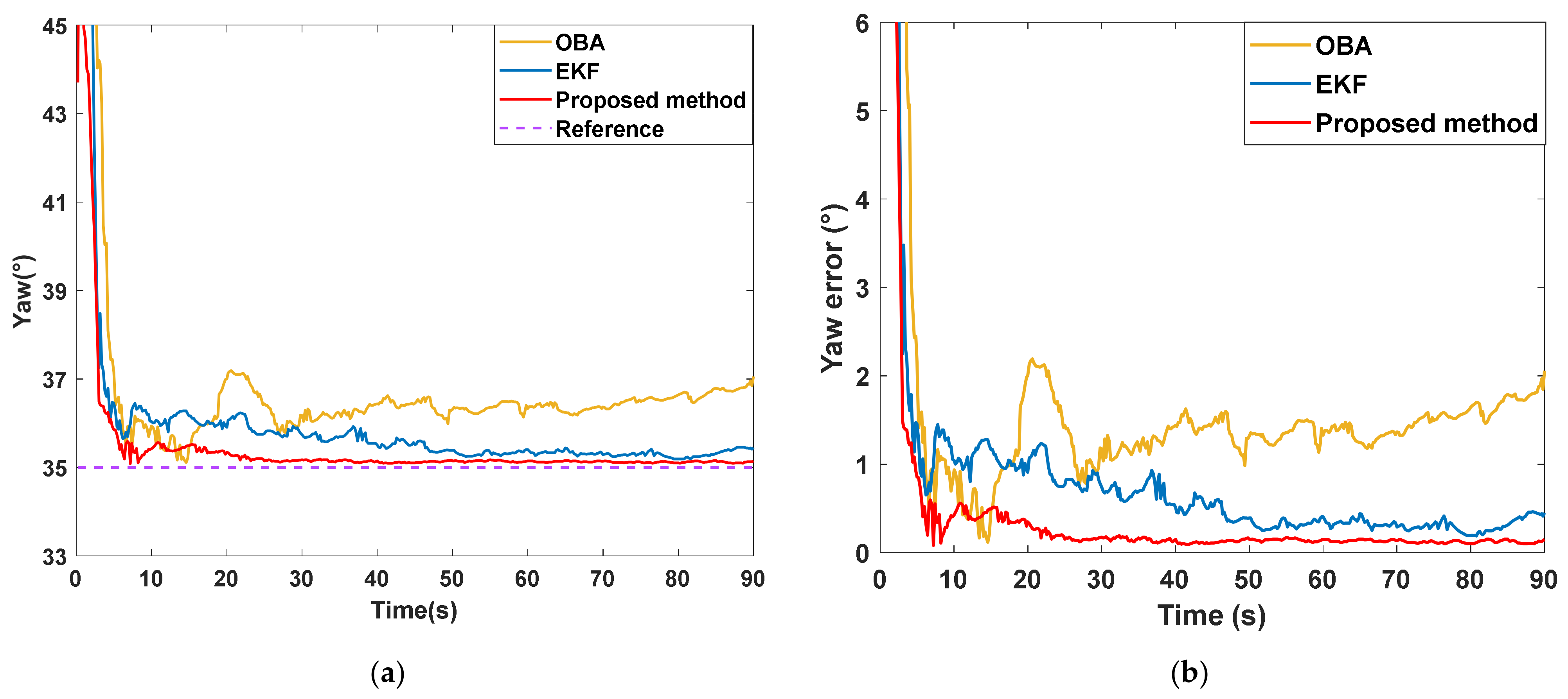
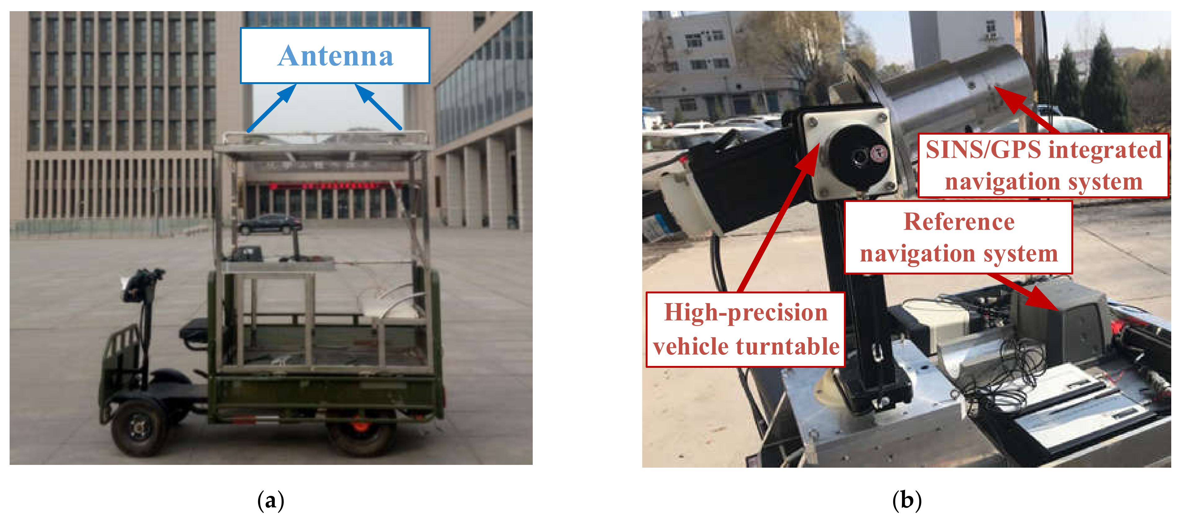
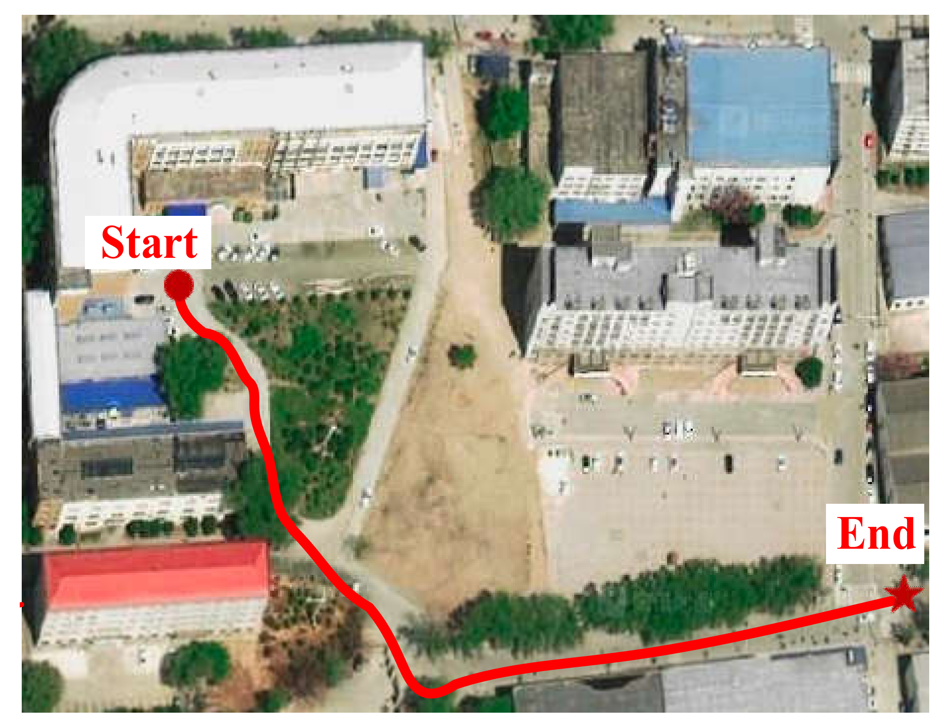
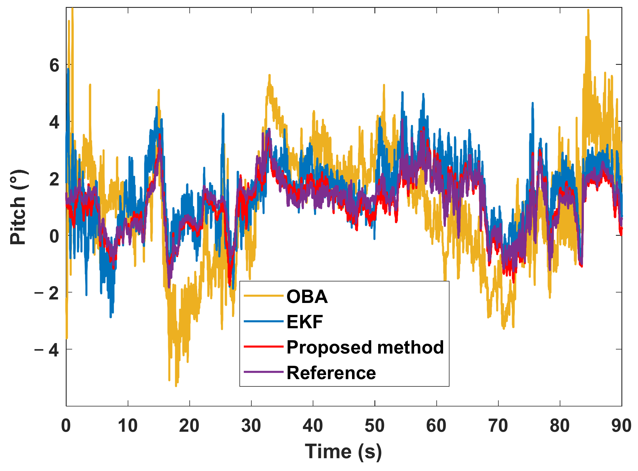
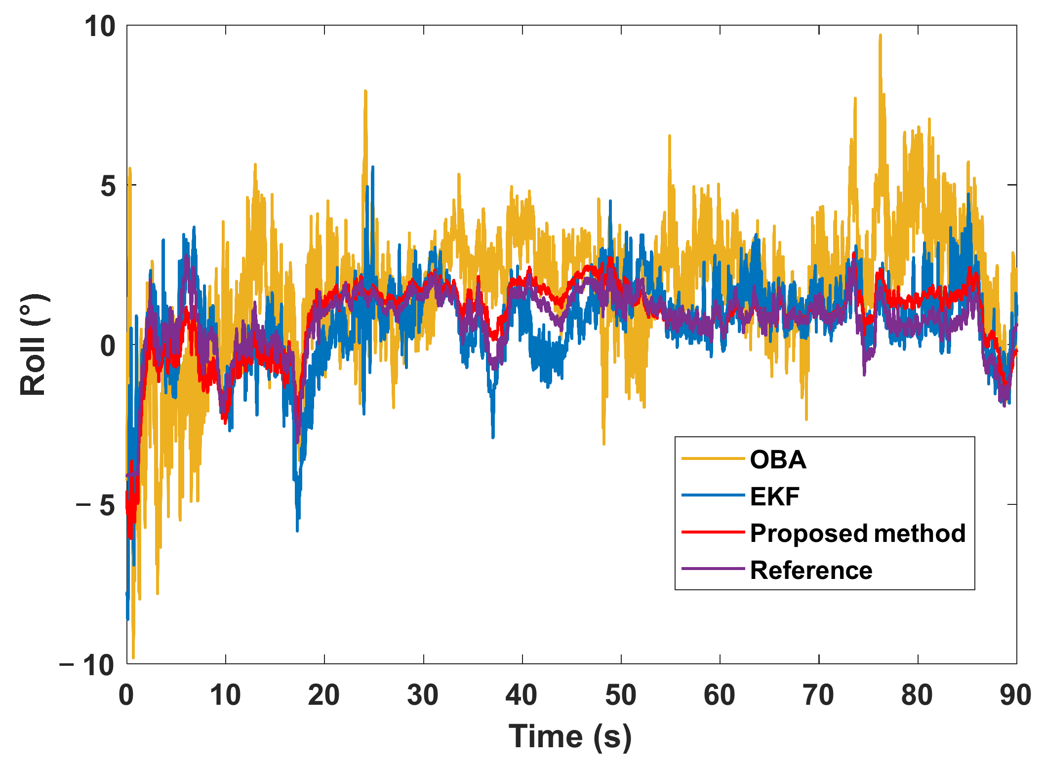
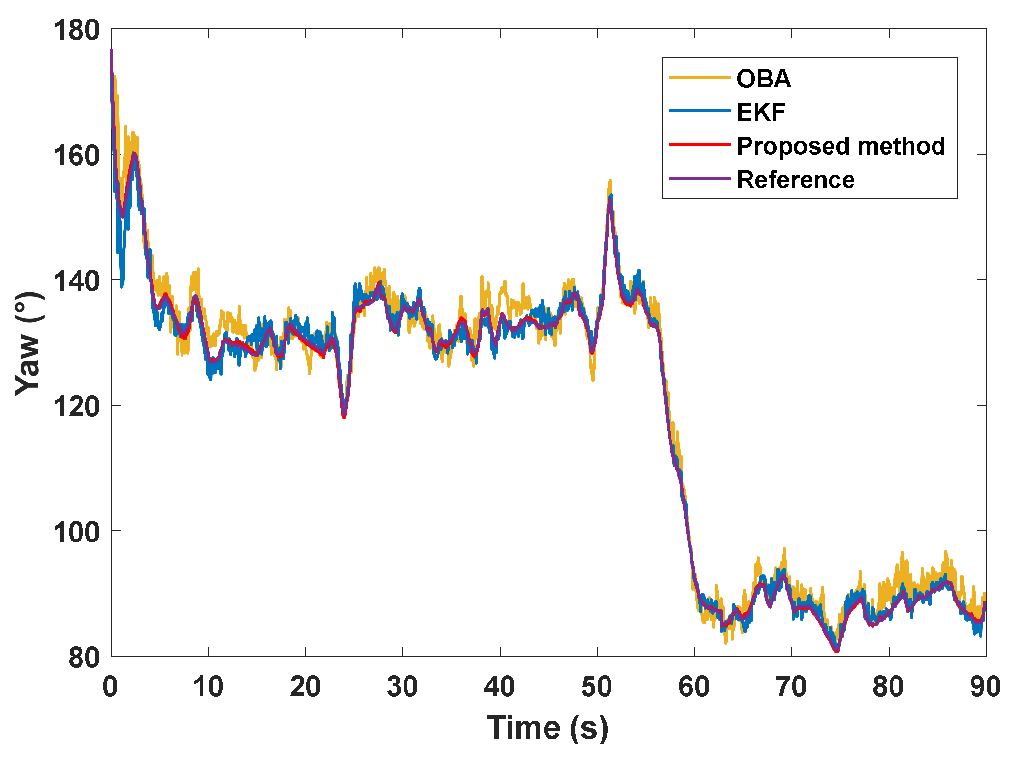
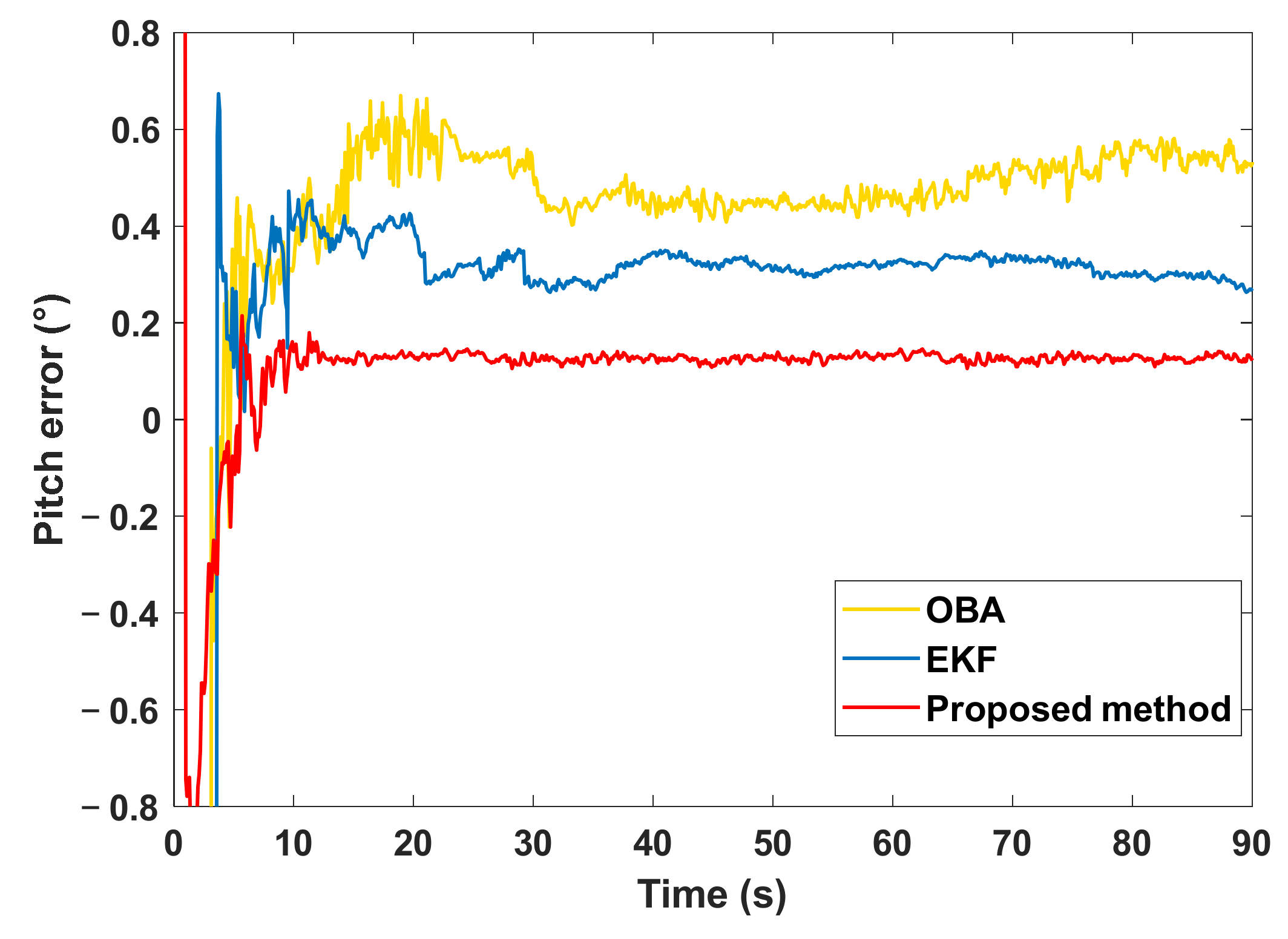
4.2. Experimental Results
5. Conclusions
Author Contributions
Funding
Data Availability Statement
Acknowledgments
Conflicts of Interest
References
- Li, N.; Guan, L.; Gao, Y.; Du, S.; Wu, M.; Guang, X.; Cong, X. Indoor and Outdoor Low-Cost Seamless Integrated Navigation System Based on the Integration of INS/GNSS/LIDAR System. Remote Sens. 2020, 12, 3271. [Google Scholar] [CrossRef]
- Li, T.; Zhang, H.; Gao, Z.; Niu, X.; El-sheimy, N. Tight Fusion of a Monocular Camera, MEMS-IMU, and Single-Frequency Multi-GNSS RTK for Precise Navigation in GNSS-Challenged Environments. Remote Sens. 2019, 11, 610. [Google Scholar] [CrossRef]
- Sun, Y. Autonomous Integrity Monitoring for Relative Navigation of Multiple Unmanned Aerial Vehicles. Remote Sens. 2021, 13, 1483. [Google Scholar] [CrossRef]
- Ge, B.; Zhang, H.; Fu, W.; Yang, J. Enhanced Redundant Measurement-Based Kalman Filter for Measurement Noise Covariance Estimation in INS/GNSS Integration. Remote Sens. 2020, 12, 3500. [Google Scholar] [CrossRef]
- Cheng, Q.; Chen, P.; Sun, R.; Wang, J.; Mao, Y.; Ochieng, W.Y. A New Faulty GNSS Measurement Detection and Exclusion Algorithm for Urban Vehicle Positioning. Remote Sens. 2021, 13, 2117. [Google Scholar] [CrossRef]
- Kim, Y.; An, J.; Lee, J. Robust Navigational System for a Transporter Using GPS/INS Fusion. IEEE Trans. Ind. Electron. 2017, 65, 3346–3354. [Google Scholar] [CrossRef]
- Chang, L.; Qin, F.; Jiang, S. Strapdown Inertial Navigation System Initial Alignment Based on Modified Process Model. IEEE Sens. J. 2019, 19, 6381–6391. [Google Scholar] [CrossRef]
- Dingjie, W.; Hanfeng, L.; Jie, W. In-flight initial alignment for small UAV MEMS-based navigation via adaptive unscented Kalman filtering approach. Aerosp. Sci. Technol. 2017, 61, 73–84. [Google Scholar]
- Dmitriyev, S.P.; Stepanov, O.A.; Shepel, S.V. Nonlinear filtering methods application in INS alignment. IEEE Trans. Aerosp. Electron. Syst. 1997, 33, 260–272. [Google Scholar] [CrossRef]
- Cao, S.; Guo, L. Multi-objective robust initial alignment algorithm for Inertial Navigation System with multiple disturbances. Aerosp. Sci. Technol. 2012, 21, 1–6. [Google Scholar] [CrossRef]
- Li, J.; Xu, J.; Chang, L.; Zha, F. An Improved Optimal Method For Initial Alignment. J. Navig. 2014, 67, 727–736. [Google Scholar] [CrossRef]
- Wu, J.; Zhou, Z.; Fourati, H.; Li, R.; Liu, M. Generalized Linear Quaternion Complementary Filter for Attitude Estimation From Multisensor Observations: An Optimization Approach. IEEE Trans. Autom. Sci. Eng. 2019, 16, 1330–1343. [Google Scholar] [CrossRef]
- Liu, J.; Zhao, T. In-flight alignment method of navigation system based on microelectromechanical systems sensor measurement. Int. J. Distrib. Sens. Netw. 2019, 15, 155014771984492. [Google Scholar] [CrossRef]
- Wu, M.; Wu, Y.; Hu, X.; Hu, D. Optimization-based alignment for inertial navigation systems: Theory and algorithm. Aerosp. Sci. Technol. 2011, 15, 1–17. [Google Scholar] [CrossRef]
- Chang, L.; Li, J.; Li, K. Optimization-based Alignment for Strapdown Inertial Navigation System Comparison and Extension. IEEE Trans. Aero. Elec. Sys. 2016, 52, 1697–1713. [Google Scholar] [CrossRef]
- Shuster, M.D. A Survey of Attitude Representations. J. Astronaut. Sci. 1993, 41, 439–517. [Google Scholar]
- Pan, C.; Qian, N.; Li, Z.; Gao, J.; Liu, Z.; Shao, K. A Robust Adaptive Cubature Kalman Filter Based on SVD for Dual-Antenna GNSS/MIMU Tightly Coupled Integration. Remote Sens. 2021, 13, 1943. [Google Scholar] [CrossRef]
- Lin, Y.; Miao, L.; Zhou, Z. An Improved MCMC-based Particle Filter for GPS-aided SINS In-motion Initial Alignment. IEEE Trans. Instrum. Meas. 2020, 69, 7895–7905. [Google Scholar] [CrossRef]
- Shao, H.; Miao, L.; Gao, W.; Shen, J. Ensemble Particle Filter Based on KLD and Its Application to Initial Alignment of the SINS in Large Misalignment Angles. IEEE Trans. Ind. Electron. 2018, 65, 8946–8955. [Google Scholar] [CrossRef]
- Atia, M.M.; Liu, S.; Nematallah, H.; Karamat, T.B.; Noureldin, A. Integrated Indoor Navigation System for Ground Vehicles With Automatic 3-D Alignment and Position Initialization. IEEE Trans. Veh. Technol. 2015, 64, 1279–1292. [Google Scholar] [CrossRef]
- Zhang, P.; Zhao, Y.; Lin, H.; Zou, J.; Wang, X.; Yang, F. A Novel GNSS Attitude Determination Method Based on Primary Baseline Switching for A Multi-Antenna Platform. Remote Sens. 2020, 12, 747. [Google Scholar] [CrossRef]
- Yang, Y.; Liu, X.; Zhang, W.; Liu, X.; Guo, Y. A Nonlinear Double Model for Multisensor-Integrated Navigation Using the Federated EKF Algorithm for Small UAVs. Sensors 2020, 20, 2974. [Google Scholar] [CrossRef] [PubMed]
- Wang, M.; Wu, W.; Zhou, P.; He, X. State transformation extended Kalman filter for GPS/SINS tightly coupled integration. GPS Solut. 2018, 22, 112. [Google Scholar] [CrossRef]
- Pei, F.; Zhu, D.; Yin, S. An In-Motion Initial Alignment Algorithm for SINS Using Lie Group Matrix Kalman Filter. In Proceedings of the 2019 Chinese Automation Congress (CAC), Hangzhou, China, 22–24 November 2019. [Google Scholar] [CrossRef]
- Yunfeng, W.; Chirikjian, G.S. Error propagation on the Euclidean group with applications to manipulator kinematics. IEEE Trans. Robot. 2006, 22, 591–602. [Google Scholar] [CrossRef]
- Joukov, V.; Ćesić, J.; Westermann, K.; Marković, I.; Petrović, I.; Kulić, D. Estimation and Observability Analysis of Human Motion on Lie Groups. IEEE Trans. Cybern. 2020, 50, 1321–1332. [Google Scholar] [CrossRef]
- Barrau, A.; Bonnabel, S. Intrinsic filtering on Lie groups with applications to attitude estimation. IEEE Trans. Automat. Contr. 2014, 60, 436–449. [Google Scholar] [CrossRef]
- Zhang, C.; Taghvaei, A.; Mehta, P.G. Feedback Particle Filter on Riemannian Manifolds and Matrix Lie Groups. IEEE Trans. Automat. Contr. 2018, 63, 2465–2480. [Google Scholar] [CrossRef]
- Celledoni, E.; Owren, B. Lie group methods for rigid body dynamics and time integration on manifolds. Comput. Methods Appl. Mech. Eng. 2003, 192, 421–438. [Google Scholar] [CrossRef]
- Kang, D.; Jang, C.; Park, F.C. Unscented Kalman Filtering for Simultaneous Estimation of Attitude and Gyroscope Bias. IEEE/ASME Trans. Mech. 2019, 24, 350–360. [Google Scholar] [CrossRef]
- Brossard, M.; Condomines, J.P. Unscented Kalman Filtering on Lie Groups. In Proceedings of the 2017 IEEE/RSJ International Conference on Intelligent Robots and Systems (IROS), Vancouver, BC, Canada, 24–28 September 2017. [Google Scholar]
- Phogat, K.S.; Chang, D.E. Invariant extended Kalman filter on matrix Lie groups. Automatica 2020, 114, 108812. [Google Scholar] [CrossRef]
- Chang, L.; Li, J.; Chen, S. Initial Alignment by Attitude Estimation for Strapdown Inertial Navigation Systems. IEEE Trans. Instrum. Meas. 2015, 64, 784–794. [Google Scholar] [CrossRef]
- Huang, Y.; Zhang, Z.; Du, S.; Li, Y.; Zhang, Y. A high-accuracy GPS-aided coarse alignment method for MEMS-based SINS. IEEE Trans. Instrum. Meas. 2020, 69, 7914–7932. [Google Scholar] [CrossRef]
- Wu, Y.; Pan, X. Velocity/Position Integration Formula Part I: Application to In-Flight Coarse Alignment. IEEE Trans. Aero. Electron. Sys. 2011, 49, 1006–1023. [Google Scholar] [CrossRef]
- Mortari, D. ESOQ-2 Single-Point Algorithm for Fast Optimal Spacecraft Attitude Determination. Am. Soc. Mech. Eng. 1997, 95, 817–826. [Google Scholar]
- Markley, F.L. Attitude Determination Using Vector Observations and the Singular Value Decomposition. J. Astronaut. Sci. 1987, 38, 245–258. [Google Scholar]
- Wu, Y.; Pan, X. Velocity/Position Integration Formula Part II: Application to Strapdown Inertial Navigation Computation. IEEE Trans. Aero. Elec. Sys. 2013, 49, 1024–1034. [Google Scholar] [CrossRef]
- Wahba, G. A Least Squares Estimate of Satellite Attitude. Siam Rev. 2006, 7, 409. [Google Scholar] [CrossRef]
- Mortari, D. Euler-q Algorithm for Attitude Determination from Vector Observations. J. Guid. Control. Dyn. 1998, 7, 328–334. [Google Scholar] [CrossRef]
- Aboutaleb, A.; El-Wakeel, A.S.; Elghamrawy, H.; Noureldin, A. LiDAR/RISS/GNSS Dynamic Integration for Land Vehicle Robust Positioning in Challenging GNSS Environments. Remote Sens. 2020, 12, 2323. [Google Scholar] [CrossRef]
- Julier, S.J. Unscented filtering and nonlinear estimation. Proc. IEEE 2004, 92, 401–422. [Google Scholar] [CrossRef]
- Turner, D.; Lucieer, A.; Wallace, L. Direct Georeferencing of Ultrahigh-Resolution UAV Imagery. IEEE Trans. Geosci. Remote Sens. 2014, 5, 2738–2745. [Google Scholar] [CrossRef]
- Wu, Q.; Li, K.; Song, T.X. The calibration for inner and outer lever-arm errors based on velocity differences of two RINSs. Mech. Syst. Signal Process. 2021, 160, 107868. [Google Scholar] [CrossRef]


| Device | Parameter | Value | Frequency |
|---|---|---|---|
| SINS | Gyro bias | 50°/h | 100 Hz |
| Gyro random walk | |||
| Accelerometer bias | 5 mg | ||
| GPS (CNS50) | Position accuracy | 2 m | 5 Hz |
| Velocity accuracy | 0.2 m/s | ||
| Time accuracy | 50 ns | ||
| Reference system (NovAtel SPAN-LCI) | Position accuracy | 1 cm ± 1 ppm | 100 Hz |
| Velocity accuracy | 0.03 m/s | ||
| Time accuracy | 20 ns | ||
| Vehicle turntable | Roll angle accuracy | 0.05° | - |
| Alignment Error | Method | Std | RMSE |
|---|---|---|---|
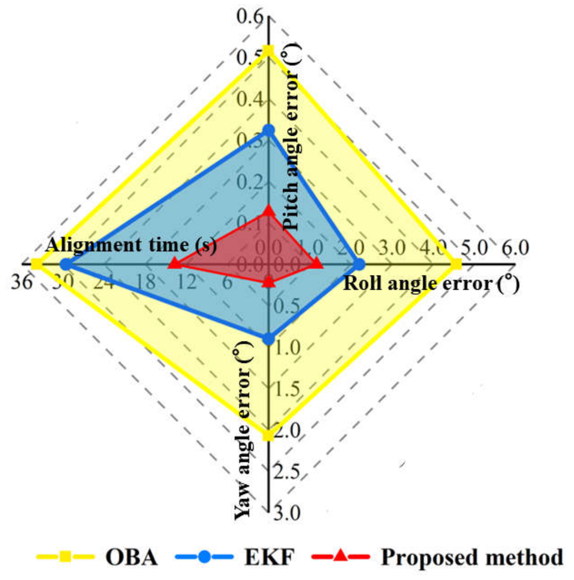
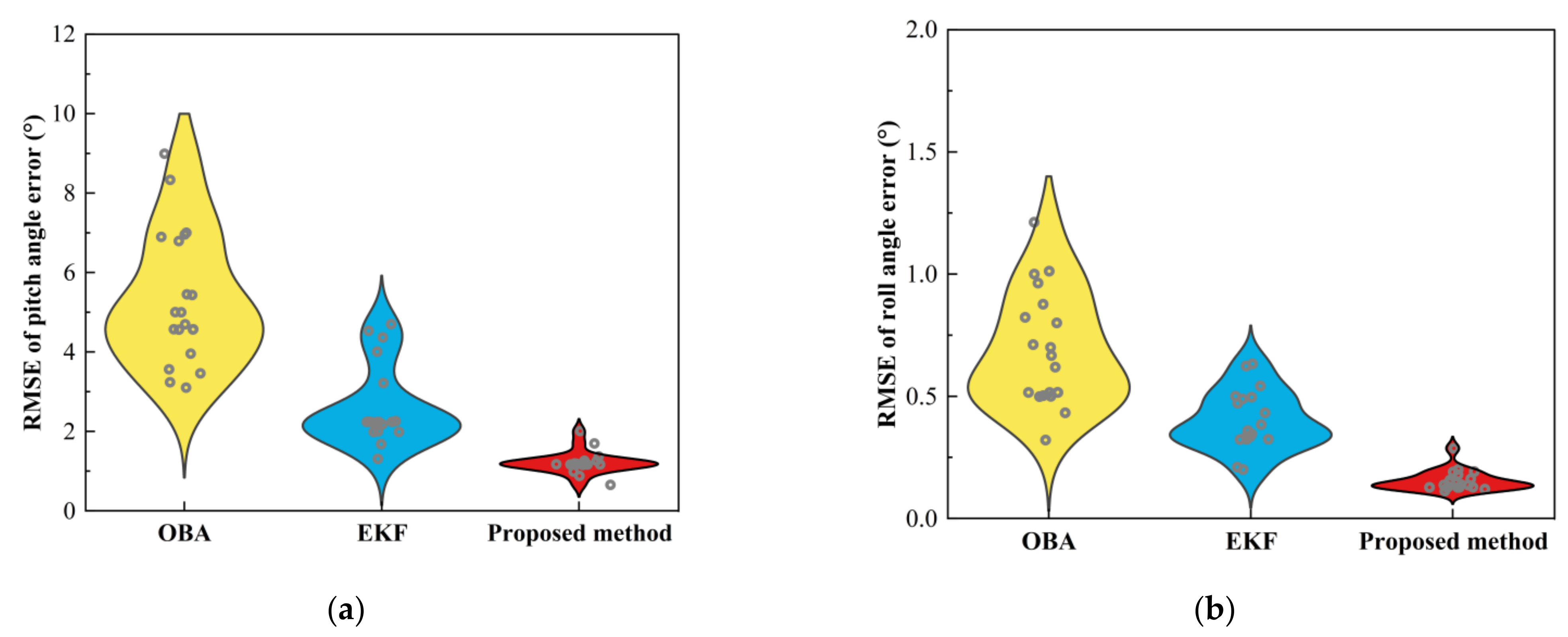
| Pitch angle error (°) | OBA | 0.04 | 0.52 |
| EKF | 0.02 | 0.32 | |
| Proposed method | 0.01 | 0.13 | |
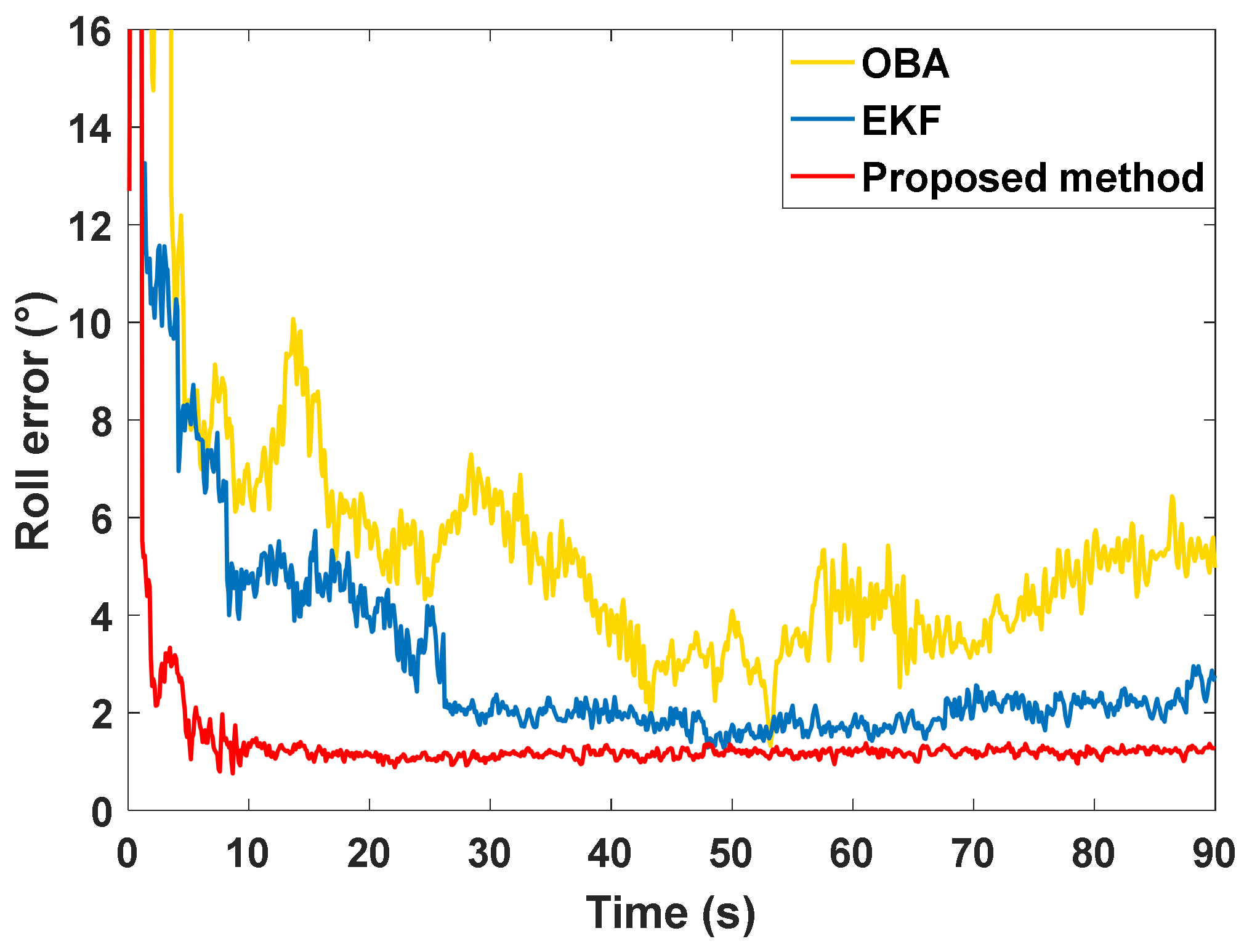
| Roll angle error (°) | OBA | 1.02 | 4.56 |
| EKF | 0.56 | 2.20 | |
| Proposed method | 0.08 | 1.16 | |
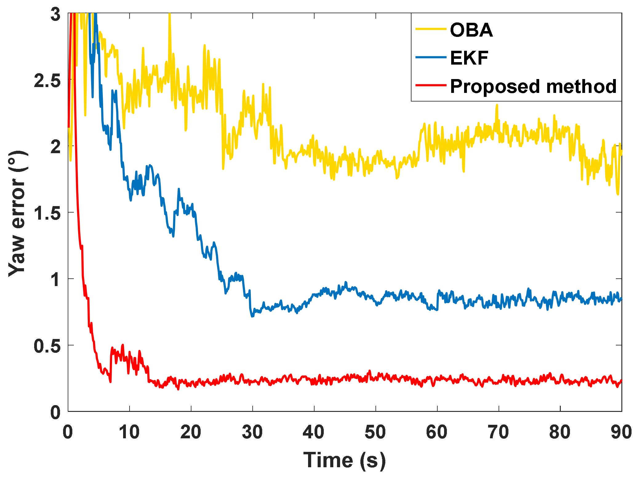
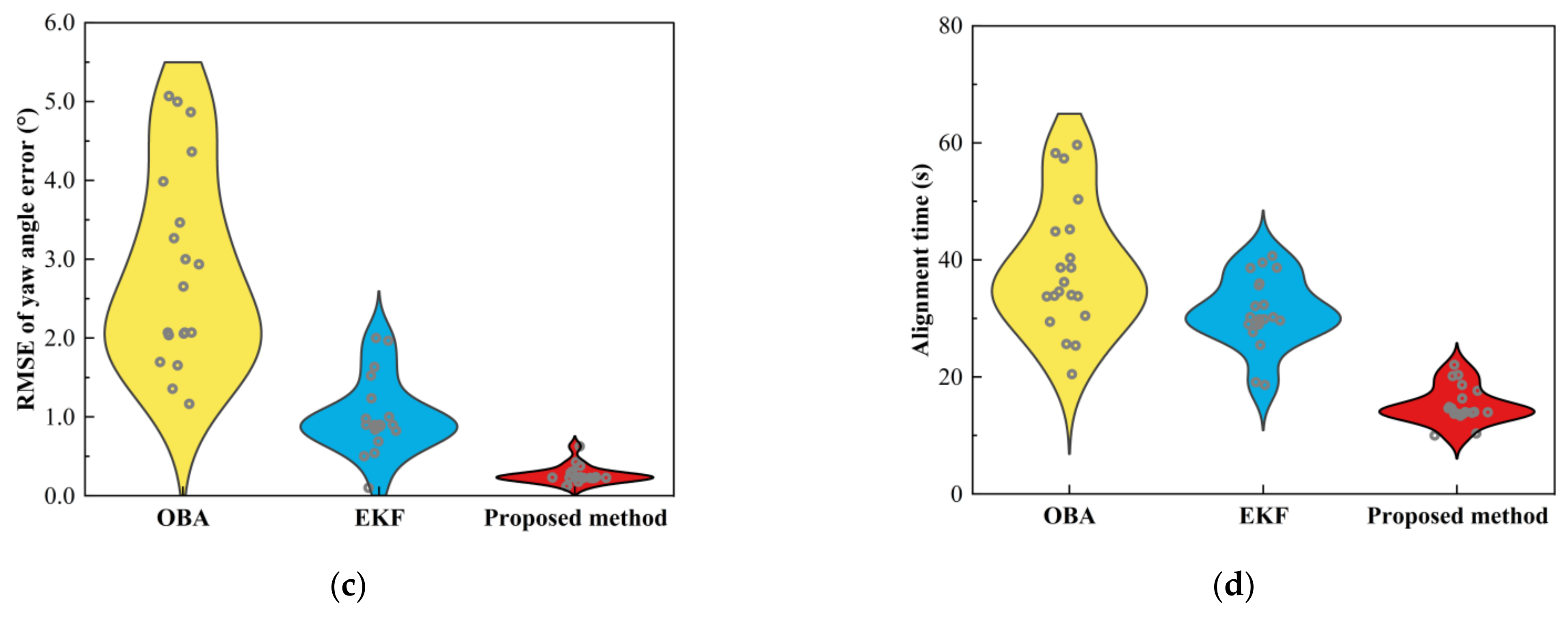
| Yaw angle error (°) | OBA | 0.18 | 2.07 |
| EKF | 0.09 | 0.90 | |
| Proposed method | 0.02 | 0.23 |
| Method | OBA | EKF | Proposed Method |
|---|---|---|---|
| Alignment time (s) | 33.79 | 29.56 | 13.71 |
Disclaimer/Publisher’s Note: The statements, opinions and data contained in all publications are solely those of the individual author(s) and contributor(s) and not of MDPI and/or the editor(s). MDPI and/or the editor(s) disclaim responsibility for any injury to people or property resulting from any ideas, methods, instructions or products referred to in the content. |
© 2023 by the authors. Licensee MDPI, Basel, Switzerland. This article is an open access article distributed under the terms and conditions of the Creative Commons Attribution (CC BY) license (https://creativecommons.org/licenses/by/4.0/).
Share and Cite
Wei, X.; Li, J.; Han, D.; Wang, J.; Zhan, Y.; Wang, X.; Feng, K. An In-Flight Alignment Method for Global Positioning System-Assisted Low Cost Strapdown Inertial Navigation System in Flight Body with Short-Endurance and High-Speed Rotation. Remote Sens. 2023, 15, 711. https://doi.org/10.3390/rs15030711
Wei X, Li J, Han D, Wang J, Zhan Y, Wang X, Feng K. An In-Flight Alignment Method for Global Positioning System-Assisted Low Cost Strapdown Inertial Navigation System in Flight Body with Short-Endurance and High-Speed Rotation. Remote Sensing. 2023; 15(3):711. https://doi.org/10.3390/rs15030711
Chicago/Turabian StyleWei, Xiaokai, Jie Li, Ding Han, Junlin Wang, Ying Zhan, Xin Wang, and Kaiqiang Feng. 2023. "An In-Flight Alignment Method for Global Positioning System-Assisted Low Cost Strapdown Inertial Navigation System in Flight Body with Short-Endurance and High-Speed Rotation" Remote Sensing 15, no. 3: 711. https://doi.org/10.3390/rs15030711
APA StyleWei, X., Li, J., Han, D., Wang, J., Zhan, Y., Wang, X., & Feng, K. (2023). An In-Flight Alignment Method for Global Positioning System-Assisted Low Cost Strapdown Inertial Navigation System in Flight Body with Short-Endurance and High-Speed Rotation. Remote Sensing, 15(3), 711. https://doi.org/10.3390/rs15030711