

A Simulation Framework of Unmanned Aerial Vehicles Route Planning Design and Validation for Landslide Monitoring


Abstract
:1. Introduction
- An UAV flight simulation approach that amalgamates UE4 and AirSim is proposed, which address challenges encountered in other simulation frameworks, including texture fidelity, asset constraints, and protocol compatibility and so on;
- Utilizing the simulation framework to optimize the flight path algorithms, substantiating the practical utility of the proposed framework, and validating the correction of the algorithms;
- Simulation technology is used in advance to simulate the actual flight, which effectively reduces the input of manpower and material costs, avoids risks, and improves the execution efficiency of actual flight tasks.
2. Methods
2.1. Landslide Terrain Modeling
2.1.1. Landslide Terrain Modeling
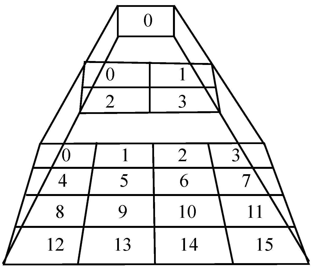
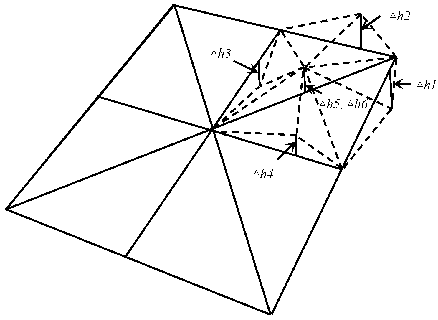
2.1.2. Levels of Detail
2.2. Simulation Framework
2.2.1. Unreal Engine
2.2.2. AirSim
2.2.3. Texture Mapping
2.2.4. Normal Mapping
2.2.5. Lighting
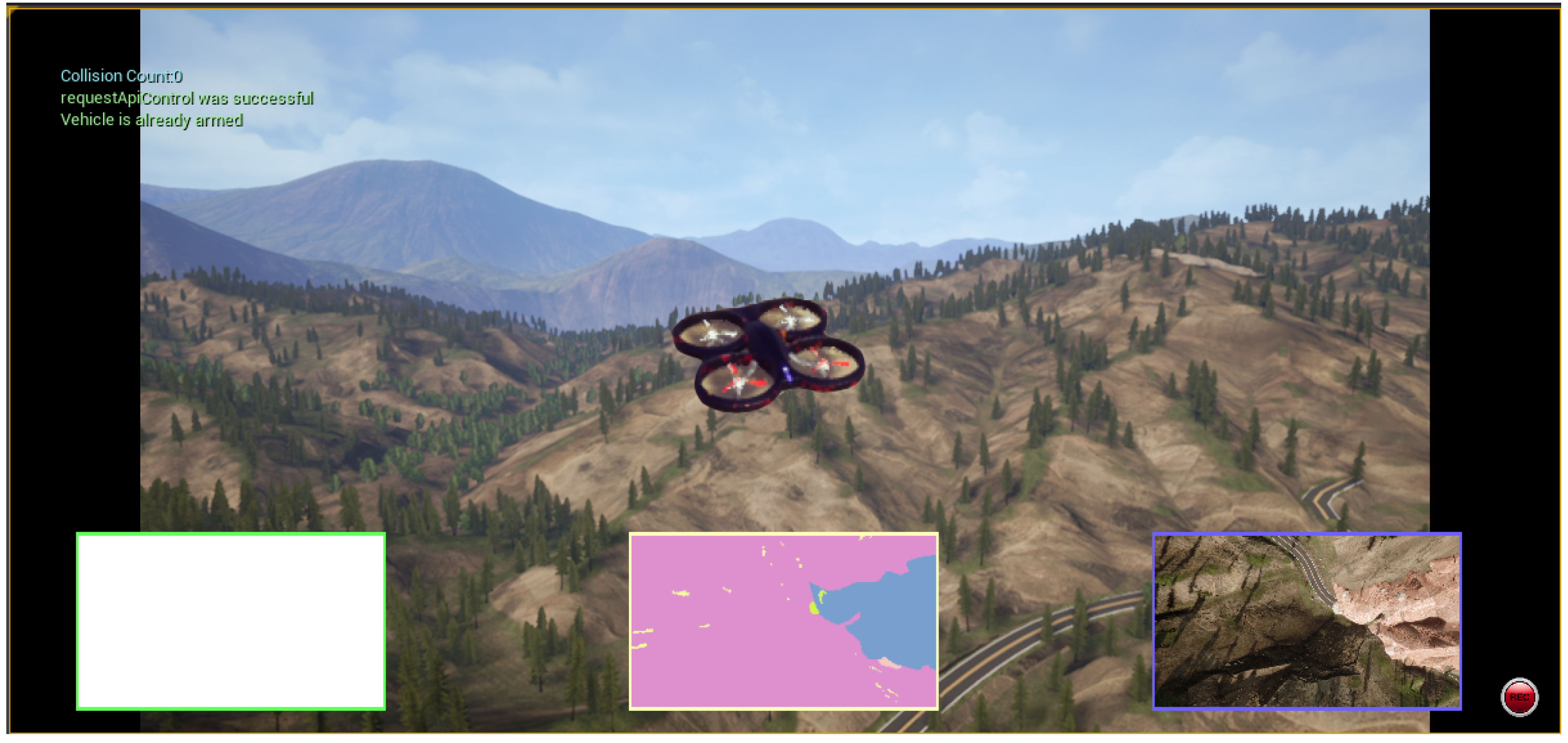
2.2.6. Unreal Engine UAV Flight Simulation
2.3. UAV Flight Route Planning
2.3.1. Traditional Flight Route Planning
2.3.2. Novel Route Planning
3. Experiment and Results
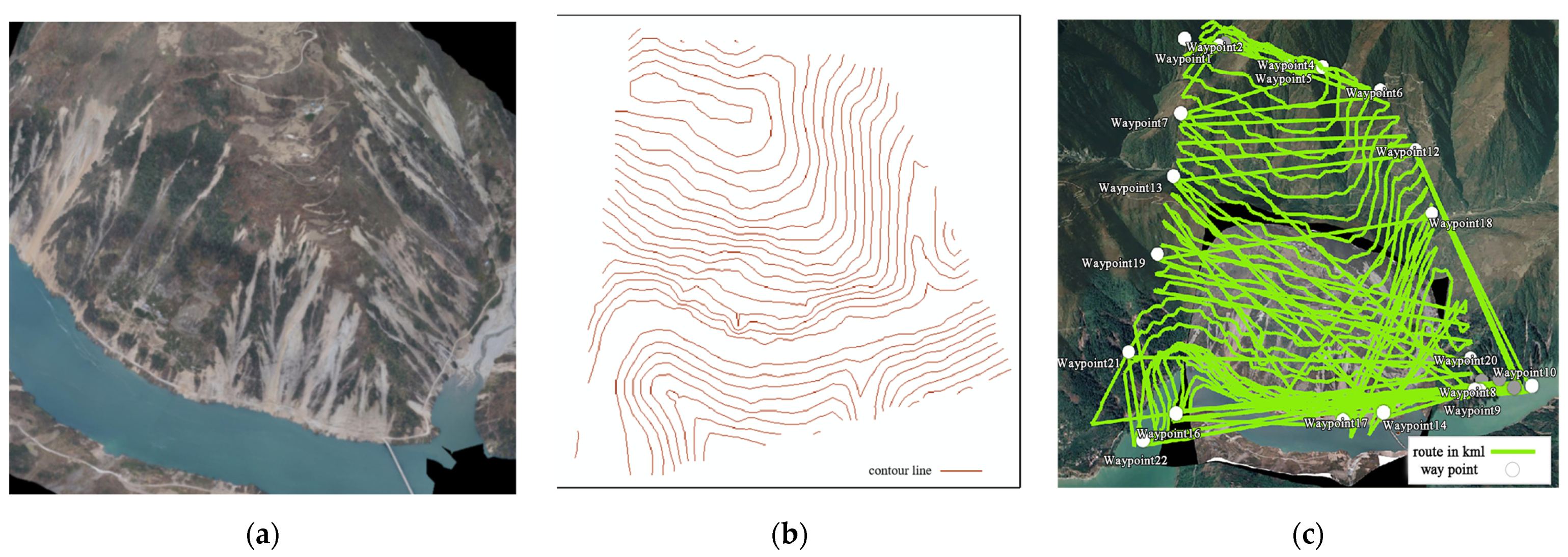
3.1. Data Set
3.2. Landslide Model Construction
3.3. UAV Flight Path Planning Simulation Implementation
3.4. Result
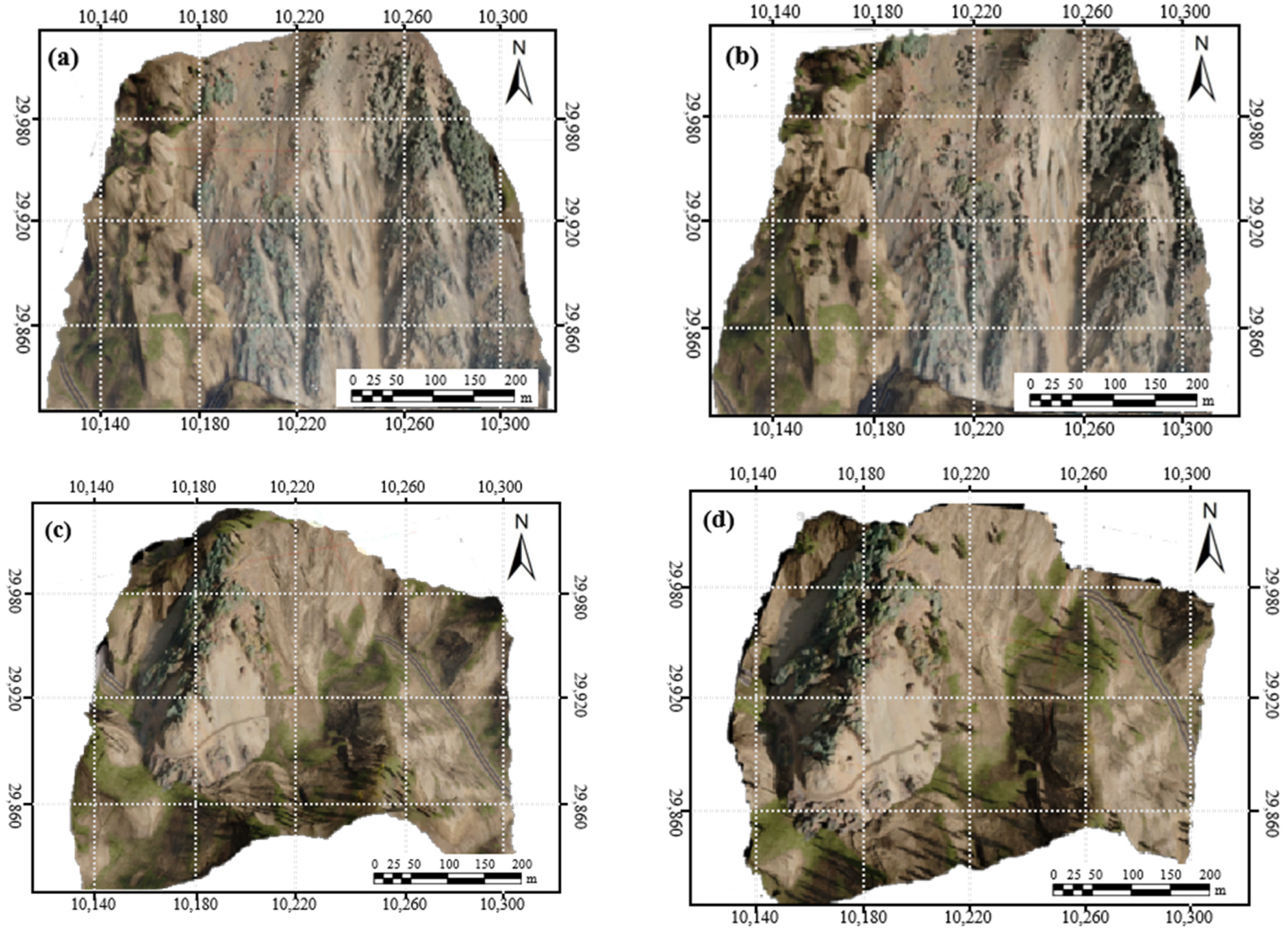
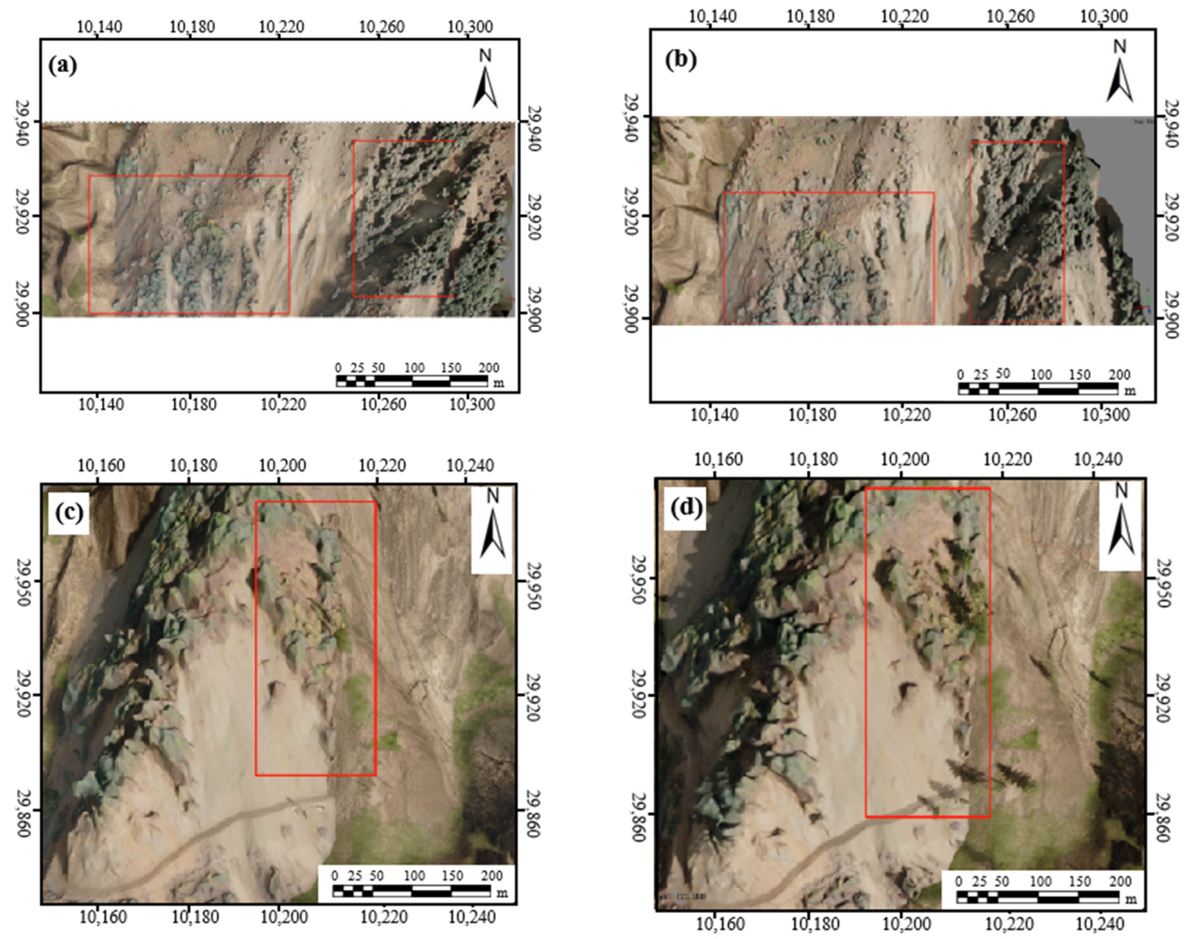
3.4.1. 3D Model Completeness
3.4.2. 3D Model Accuracy
4. Discussion
5. Conclusions
Author Contributions
Funding
Data Availability Statement
Conflicts of Interest
References
- Yao, W.; Li, C.; Zhan, H.; Zhou, J.-Q.; Criss, R.E.; Xiong, S.; Jiang, X. Multiscale Study of Physical and Mechanical Properties of Sandstone in Three Gorges Reservoir Region Subjected to Cyclic Wetting–Drying of Yangtze River Water. Rock. Mech. Rock. Eng. 2020, 53, 2215–2231. [Google Scholar] [CrossRef]
- Guzzetti, F.; Gariano, S.L.; Peruccacci, S.; Brunetti, M.T.; Marchesini, I.; Rossi, M.; Melillo, M. Geographical Landslide Early Warning Systems. Earth-Sci. Rev. 2020, 200, 102973. [Google Scholar] [CrossRef]
- Gariano, S.L.; Guzzetti, F. Landslides in a Changing Climate. Earth-Sci. Rev. 2016, 162, 227–252. [Google Scholar] [CrossRef]
- Nguyen, B.-Q.-V.; Kim, Y.-T. Regional-Scale Landslide Risk Assessment on Mt. Umyeon Using Risk Index Estimation. Landslides 2021, 18, 2547–2564. [Google Scholar] [CrossRef]
- Chen, G.; Meng, X.; Qiao, L.; Zhang, Y.; Wang, S. Response of a Loess Landslide to Rainfall: Observations from a Field Artificial Rainfall Experiment in Bailong River Basin, China. Landslides 2018, 15, 895–911. [Google Scholar] [CrossRef]
- Tang, Y.; Feng, F.; Guo, Z.; Feng, W.; Li, Z.; Wang, J.; Sun, Q.; Ma, H.; Li, Y. Integrating Principal Component Analysis with Statistically-Based Models for Analysis of Causal Factors and Landslide Susceptibility Mapping: A Comparative Study from the Loess Plateau Area in Shanxi (China). J. Clean. Prod. 2020, 277, 124159. [Google Scholar] [CrossRef]
- Huang, Y.; Zhao, L. Review on Landslide Susceptibility Mapping Using Support Vector Machines. Catena 2018, 165, 520–529. [Google Scholar] [CrossRef]
- Wang, C.; Chang, L.; Wang, X.; Zhang, B.; Stein, A. A Review of InSAR Statistical Inference in Deformation Measurement and Geophysical Inversion. IEEE Geosci. Remote Sens. Mag.
- Teo, T.-A.; Fu, Y.-J.; Li, K.-W.; Weng, M.-C.; Yang, C.-M. Comparison between Image-and Surface-Derived Displacement Fields for Landslide Monitoring Using an Unmanned Aerial Vehicle. Int. J. Appl. Earth Obs. Geoinf. 2023, 116, 103164. [Google Scholar] [CrossRef]
- Kaleem, Z.; Rehmani, M.H. Amateur Drone Monitoring: State-of-the-Art Architectures, Key Enabling Technologies, and Future Research Directions. IEEE Wirel. Commun. 2018, 25, 150–159. [Google Scholar] [CrossRef]
- Khachumov, M.; Khachumov, V. Optimization Models of UAV Route Planning For Forest Fire Monitoring. In Proceedings of the 2022 International Russian Automation Conference (RusAutoCon), Sochi, Russian, 4–10 September 2022; IEEE: New York, NY, USA, 2022; pp. 272–277. [Google Scholar]
- Zhou, Z.; Feng, J.; Gu, B.; Ai, B.; Mumtaz, S.; Rodriguez, J.; Guizani, M. When Mobile Crowd Sensing Meets UAV: Energy-Efficient Task Assignment and Route Planning. IEEE Trans. Commun. 2018, 66, 5526–5538. [Google Scholar] [CrossRef]
- Kim, S.-H.; Padilla, G.E.G.; Kim, K.-J.; Yu, K.-H. Flight Path Planning for a Solar Powered UAV in Wind Fields Using Direct Collocation. IEEE Trans. Aerosp. Electron. Syst. 2020, 56, 1094–1105. [Google Scholar] [CrossRef]
- Battulwar, R.; Winkelmaier, G.; Valencia, J.; Naghadehi, M.Z.; Peik, B.; Abbasi, B.; Parvin, B.; Sattarvand, J. A Practical Methodology for Generating High-Resolution 3D Models of Open-Pit Slopes Using UAVs: Flight Path Planning and Optimization. Remote Sens. 2020, 12, 2283. [Google Scholar] [CrossRef]
- D’Urso, F.; Santoro, C.; Santoro, F.F. An Integrated Framework for the Realistic Simulation of Multi-UAV Applications. Comput. Electr. Eng. 2019, 74, 196–209. [Google Scholar] [CrossRef]
- Shao, X.; Shi, Y.; Zhang, W. Fault-Tolerant Quantized Control for Flexible Air-Breathing Hypersonic Vehicles with Appointed-Time Tracking Performances. IEEE Trans. Aerosp. Electron. Syst. 2020, 57, 1261–1273. [Google Scholar] [CrossRef]
- Hentati, A.I.; Krichen, L.; Fourati, M.; Fourati, L.C. Simulation Tools, Environments and Frameworks for UAV Systems Performance Analysis. In Proceedings of the 2018 14th International Wireless Communications & Mobile Computing Conference (IWCMC), Limassol, Cyprus, 25–29 June 2018; IEEE: New York, NY, USA, 2018; pp. 1495–1500. [Google Scholar]
- X-Plane 12 Flight Simulator—X-Plane. Available online: https://www.x-plane.com/ (accessed on 27 September 2023).
- Wang, Z.; Li, J. 3D Simulation of Flight Control System for Quad Tilt Rotor UAV Based on Flightgear. IOP Conf. Ser. Earth Environ. Sci. 2020, 440, 052056. [Google Scholar] [CrossRef]
- Gazebo. Available online: https://gazebosim.org/home (accessed on 27 September 2023).
- Matlekovic, L.; Juric, F.; Schneider-Kamp, P. Microservices for Autonomous UAV Inspection with UAV Simulation as a Service. Simul. Model. Pract. Theory 2022, 119, 102548. [Google Scholar] [CrossRef]
- Ling, H.; Luo, H.; Chen, H.; Bai, L.; Zhu, T.; Wang, Y. Modelling and Simulation of Distributed UAV Swarm Cooperative Planning and Perception. Int. J. Aerosp. Eng. 2021, 2021, 9977262. [Google Scholar] [CrossRef]
- Fernando, H.; De Silva, A.T.A.; De Zoysa, M.D.C.; Dilshan, K.; Munasinghe, S.R. Modelling, Simulation and Implementation of a Quadrotor UAV. In Proceedings of the 2013 IEEE 8th International Conference on Industrial and Information Systems, Peradeniya, Sri Lanka, 17–20 December 2013; IEEE: New York, NY, USA, 2013; pp. 207–212. [Google Scholar]
- Park, S.; Lee, S.; Im, B.; Lee, D.; Shin, S. Improvement of a Multi-Rotor UAV Flight Response Simulation Influenced by Gust. Aerosp. Sci. Technol. 2023, 134, 108156. [Google Scholar] [CrossRef]
- Song, Y.; Naji, S.; Kaufmann, E.; Loquercio, A.; Scaramuzza, D. Flightmare: A Flexible Quadrotor Simulator. In Proceedings of the 2020 Conference on Robot Learning, PMLR, Cambridge MA, USA, 4 October 2021; pp. 1147–1157. [Google Scholar]
- Benjamin, A.R.; O’Brien, D.; Barnes, G.; Wilkinson, B.E.; Volkmann, W. Improving Data Acquisition Efficiency: Systematic Accuracy Evaluation of GNSS-Assisted Aerial Triangulation in UAS Operations. J. Surv. Eng. 2020, 146, 05019006. [Google Scholar] [CrossRef]
- Wen, X.; Xie, H.; Liu, H.; Yan, L. Accurate Reconstruction of the LoD3 Building Model by Integrating Multi-Source Point Clouds and Oblique Remote Sensing Imagery. ISPRS Int. J. Geo-Inf. 2019, 8, 135. [Google Scholar] [CrossRef]
- Xiong, C.; Lu, X.; Huang, J.; Guan, H. Multi-LOD Seismic-Damage Simulation of Urban Buildings and Case Study in Beijing CBD. Bull. Earthquake Eng. 2019, 17, 2037–2057. [Google Scholar] [CrossRef]
- Yijun, Z.; Jiadong, X.; Chen, L. A Fast Bi-Directional A* Algorithm Based on Quad-Tree Decomposition and Hierarchical Map. IEEE Access 2021, 9, 102877–102885. [Google Scholar] [CrossRef]
- Chen, Q.; Liu, G.; Ma, X.; Mariethoz, G.; He, Z.; Tian, Y.; Weng, Z. Local Curvature Entropy-Based 3D Terrain Representation Using a Comprehensive Quadtree. ISPRS J. Photogramm. Remote Sens. 2018, 139, 30–45. [Google Scholar] [CrossRef]
- Qiu, W.; Yuille, A. Unrealcv: Connecting Computer Vision to Unreal Engine. In Proceedings of the Computer Vision–ECCV 2016 Workshops, Amsterdam, The Netherlands, 8–10, 15–16 October 2016; Part III 14. Springer: Berlin/Heidelberg, Germany, 2016; pp. 909–916. [Google Scholar]
- Shah, S.; Dey, D.; Lovett, C.; Kapoor, A. Airsim: High-Fidelity Visual and Physical Simulation for Autonomous Vehicles. In Proceedings of the Field and Service Robotics: Results of the 11th International Conference, Zurich, Switzerland, 12–15 September 2017; pp. 621–635. [Google Scholar]
- AirSim. Available online: https://github.com/microsoft/AirSim/ (accessed on 28 September 2023).
- Li, Z.; Zhang, Y.-D. 3D Reconstruction Method of Forest Landscape Based on Virtual Reality. Multimed. Tools Appl. 2020, 79, 16369–16383. [Google Scholar] [CrossRef]
- Sanchez, G.M.E.; Van Renterghem, T.; Sun, K.; De Coensel, B.; Botteldooren, D. Using Virtual Reality for Assessing the Role of Noise in the Audio-Visual Design of an Urban Public Space. Landsc. Urban. Plan. 2017, 167, 98–107. [Google Scholar] [CrossRef]
- Gil-Tena, A.; Aquilué, N.; Duane, A.; De Cáceres, M.; Brotons, L. Mediterranean Fire Regime Effects on Pine-Oak Forest Landscape Mosaics under Global Change in NE Spain. Eur. J. For. Res. 2016, 135, 403–416. [Google Scholar] [CrossRef]
- Xu, Y.; Zhu, X.; Shi, J.; Zhang, G.; Bao, H.; Li, H. Depth Completion From Sparse LiDAR Data With Depth-Normal Constraints. In Proceedings of the 2019 IEEE/CVF International Conference on Computer Vision (ICCV), Seoul, Republic of Korea, 27 October–2 November 2019; pp. 2811–2820. [Google Scholar]
- Shen, J.; Cashman, T.J.; Ye, Q.; Hutton, T.; Sharp, T.; Bogo, F.; Fitzgibbon, A.; Shotton, J. The Phong Surface: Efficient 3D Model Fitting Using Lifted Optimization. In Computer Vision—ECCV 2020; Vedaldi, A., Bischof, H., Brox, T., Frahm, J.-M., Eds.; Lecture Notes in Computer Science; Springer International Publishing: Cham, Switzerland, 2020; Volume 12346, pp. 687–703. ISBN 978-3-030-58451-1. [Google Scholar]
- Gao, Y.; Li, Q.; Yan, B.; Guo, S. A Blinn-Phong Light Enhancement Algorithm Based on the Gradient of Voxel. In Proceedings of the 2019 International Conference on Computer, Network, Communication and Information Systems (CNCI 2019), Qingdao, China, 27–29 March 2019; Atlantis Press: Amsterdam, The Netherlands, 2019; pp. 17–23. [Google Scholar]
- Sun, L.; Liang, Y. The Impact Factor Analysis on the Improved Cook-Torrance Bidirectional Reflectance Distribution Function of Rough Surfaces. In Proceedings of the Fifth Euro-China Conference on Intelligent Data Analysis and Applications; Krömer, P., Zhang, H., Liang, Y., Pan, J.-S., Eds.; Advances in Intelligent Systems and Computing; Springer International Publishing: Cham, Switzerland, 2019; Volume 891, pp. 463–470. ISBN 978-3-030-03765-9. [Google Scholar]
- Jiddi, S.; Robert, P.; Marchand, E. Detecting Specular Reflections and Cast Shadows to Estimate Reflectance and Illumination of Dynamic Indoor Scenes. IEEE Trans. Visual. Comput. Graphics 2022, 28, 1249–1260. [Google Scholar] [CrossRef]
- He, T.; Zeng, Y.; Hu, Z. Research of Multi-Rotor UAVs Detailed Autonomous Inspection Technology of Transmission Lines Based on Route Planning. IEEE Access 2019, 7, 114955–114965. [Google Scholar] [CrossRef]
- Liu, J.; Li, H.; Yang, Z.; Wu, K.; Liu, Y.; Liu, R.W. Adaptive Douglas-Peucker Algorithm with Automatic Thresholding for AIS-Based Vessel Trajectory Compression. IEEE Access 2019, 7, 150677–150692. [Google Scholar] [CrossRef]
- Skypixel. Available online: https://www.skypixel.com/ (accessed on 28 September 2023).


| FlightGear | XPlane | JMavSim | Gazebo | AirSim | UE4Sim | |
|---|---|---|---|---|---|---|
| Commercial Free | Free | Commercial | Free | Free | Free | Free |
| Vehicles | Airplanes | AIrplanes | Multirotor | Multirotor and robots | Multirotor | Multirotor, cars |
| Scene Fidelity | High | Medium | Low | Low | Low | Low |
| Interface ROS | No | No | Yes | Yes | No | No |
| Sensors | Diversity of sensors | Easy incorporation of sensors | No incorporation of sensors | Easy modification of sensors | Monocular depth cameras | Easy modification of sensors |
| Obstacles | Yes | Yes | No | Yes | Yes | Yes |
| SITL-HITL | Yes | Yes | Yes | Yes | Yes | No |
| MAVLink | Yes | Yes | Yes | Yes | Yes | No |
| Ease of Development | Medium | Medium | High | High | Medium | Medium |
| Type of Landslide | Flying Height/m | Route Mode | Flight Runtime/s | Time Interval/s | Flight Distance/m | Ground Resolution/cm/px | Number of Images/Sheet |
|---|---|---|---|---|---|---|---|
| Compound type | 0–360 | traditional method | 256 | 2 | 1024 | 10.6 | 128 |
| Novel method | 250 | 1024 | 8 | 125 | |||
| Steep type | 0–200 | traditional method | 264 | 3 | 1024 | 11.92 | 88 |
| Novel method | 255 | 1024 | 7 | 85 |
| Type of Landslide | Route Type | RMSE/cm | 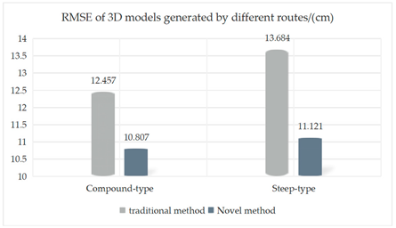 |
| Compound type | Traditional method | 12.457 | |
| Novel method | 10.807 | ||
| Steep type | Traditional method | 13.684 | |
| Novel method | 11.121 |
Disclaimer/Publisher’s Note: The statements, opinions and data contained in all publications are solely those of the individual author(s) and contributor(s) and not of MDPI and/or the editor(s). MDPI and/or the editor(s) disclaim responsibility for any injury to people or property resulting from any ideas, methods, instructions or products referred to in the content. |
© 2023 by the authors. Licensee MDPI, Basel, Switzerland. This article is an open access article distributed under the terms and conditions of the Creative Commons Attribution (CC BY) license (https://creativecommons.org/licenses/by/4.0/).
Share and Cite
Xie, D.; Hu, R.; Wang, C.; Zhu, C.; Xu, H.; Li, Q. A Simulation Framework of Unmanned Aerial Vehicles Route Planning Design and Validation for Landslide Monitoring. Remote Sens. 2023, 15, 5758. https://doi.org/10.3390/rs15245758
Xie D, Hu R, Wang C, Zhu C, Xu H, Li Q. A Simulation Framework of Unmanned Aerial Vehicles Route Planning Design and Validation for Landslide Monitoring. Remote Sensing. 2023; 15(24):5758. https://doi.org/10.3390/rs15245758
Chicago/Turabian StyleXie, Dongmei, Ruifeng Hu, Chisheng Wang, Chuanhua Zhu, Hui Xu, and Qipei Li. 2023. "A Simulation Framework of Unmanned Aerial Vehicles Route Planning Design and Validation for Landslide Monitoring" Remote Sensing 15, no. 24: 5758. https://doi.org/10.3390/rs15245758
APA StyleXie, D., Hu, R., Wang, C., Zhu, C., Xu, H., & Li, Q. (2023). A Simulation Framework of Unmanned Aerial Vehicles Route Planning Design and Validation for Landslide Monitoring. Remote Sensing, 15(24), 5758. https://doi.org/10.3390/rs15245758