Nonrigid Point Cloud Registration Using Piecewise Tricubic Polynomials as Transformation Model
Abstract
:1. Introduction
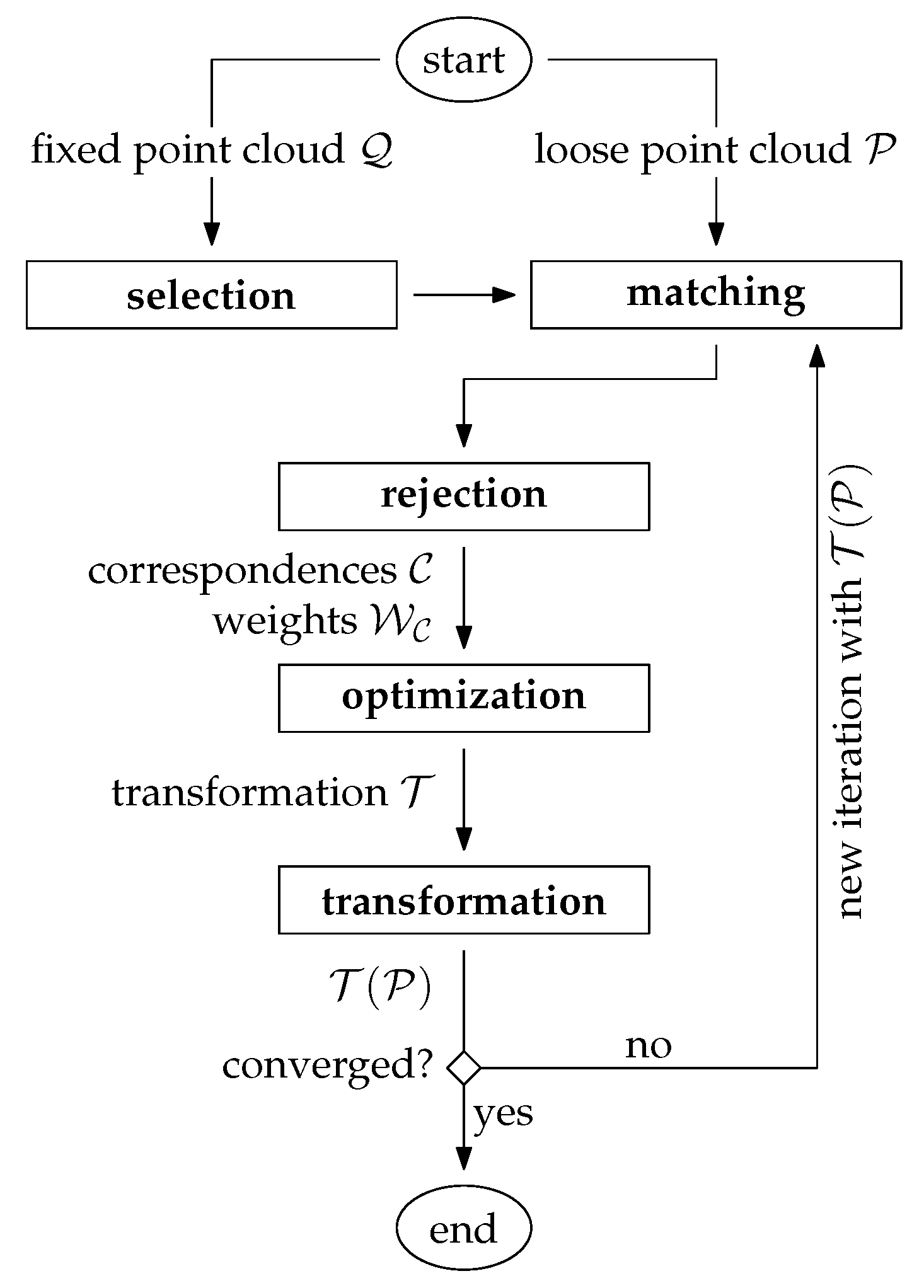
- Selection: A subset of points (instead of using each point) is selected within the overlap area in one point cloud [3]. For this, the fixed point cloud is typically chosen.
- Matching: The points, which correspond to the selected subset, are determined in the other point cloud, typically the loose point cloud .
- Rejection: False correspondences (outliers) are rejected on the basis of the compatibility of points. The result of these first three stages is a set of correspondences with an associated set of weights .
- Optimization: The transformation for the loose point cloud is estimated by minimizing the weighted and squared distances (e.g., the Euclidean distances) between corresponding points.
- Transformation: The estimated transformation is applied to the loose point cloud: .
1.1. Variants of Point Cloud Registration Algorithms
- Coarse registration vs. fine registration: Often the initial relative orientation of the point clouds is unknown in advance, e.g., if an object or a scene is scanned from multiple arbitrary view points. The problem of finding an initial transformation between the point clouds in the global parameter space is often denoted as coarse registration. Solutions to this problem are typically heavily based on matching of orientation-invariant point descriptors [9]. The 3DMatch benchmark introduced by [10] evaluates the performance of 2D and 3D descriptors for the coarse registration problem. Once a coarse registration of the point clouds is found that lies in the convergence basin of the global minima, a local optimization, typically some variant of the ICP algorithm, can be applied for the fine registration. It is noted that in case of multisensor setups, the coarse registration is often observed by means of other sensor modalities. For instance, in case of dynamic laser scanning systems, e.g., airborne laser scanning (ALS) or mobile laser scanning (MLS), the coarse registration between overlapping point clouds is directly given through the GNSS/IMU trajectory of the platform—in such cases, only a refinement of the point cloud registration is needed, e.g., by strip adjustment or (visual-)lidar SLAM (see below).
- Rigid transformation vs. nonrigid transformation: Rigid methods apply a rigid-body transformation to one of the two point clouds to improve their relative alignment. A rigid-body transformation has 3/6 degrees of freedom (DoF) in 2D/3D and is usually parameterized through a 2D/3D translation vector and 1/3 Euler angles. In contrast, nonrigid methods have usually a much higher number of DoF in order to model more complex transformations. Consequently, the estimation of a nonrigid transformation field requires a much larger number of correspondences. Another challenging problem is the choice of a proper representation of the transformation field: on the one hand, it must be flexible enough to model systematic discrepancies between the point clouds, and on the other hand, overfitting and excessive computational costs must be avoided. We will discuss these and other aspects in Section 1.2 and Section 3.
- Traditional vs. learning based: Traditional methods are based entirely on handcrafted, mostly geometric relationships. This may also include the design of handcrafted descriptive point features used in the matching step. Recent advances in the field of point cloud registration, however, have been clearly dominated by deep-learning-based methods—a recent survey is given by [11]. Such methods are especially useful for finding a coarse initial transformation between the point clouds, i.e., to solve the coarse registration problem. In such scenarios, deep-learning-based methods typically lead to a better estimate of the initial transformation by automatically learning more robust and distinct point feature representations. This is particularly useful in the presence of repetitive or symmetric scene elements, weak geometric features, or low-overlap scenarios [6]. Recently, deep-learning-based methods have also been published for the nonrigid registration problem, e.g., HPLFlowNet [12] or FlowNet3D [13].
- Pairwise vs. multiview: The majority of registration algorithms can handle a single pair of point clouds only. In practice, however, objects are typically observed from multiple viewpoints. As a consequence, a single point cloud generally overlaps with >1 other point clouds. In such cases, a global (or joint) optimization of all point clouds is highly recommended. Such an optimization problem is often interpreted as a graph where each node corresponds to an individual point cloud with associated transformation and the edges are either the correspondences themselves (single-step approach, e.g., [14]) or the pairwise transformations estimated individually in a preprocessing step (two-step approach, e.g., [15,16,17]).
- Full overlap vs. partial overlap Many algorithms (particularly also in the context of nonrigid transformations, e.g., [18,19]) assume that the two point clouds are fully overlapping. However, in practice, a single point cloud often corresponds only to a small portion of the observed scene, e.g., when scanning an object from multiple viewpoints. It is particularly difficult to find valid correspondences (under the assumption that the point clouds are not roughly aligned) in low-overlap scenarios, e.g., point clouds with an overlap below 30%. This challenge is addressed by [7] and the therein introduced 3DLoMatch benchmark, where the algorithm by [20] currently leads to the best results.
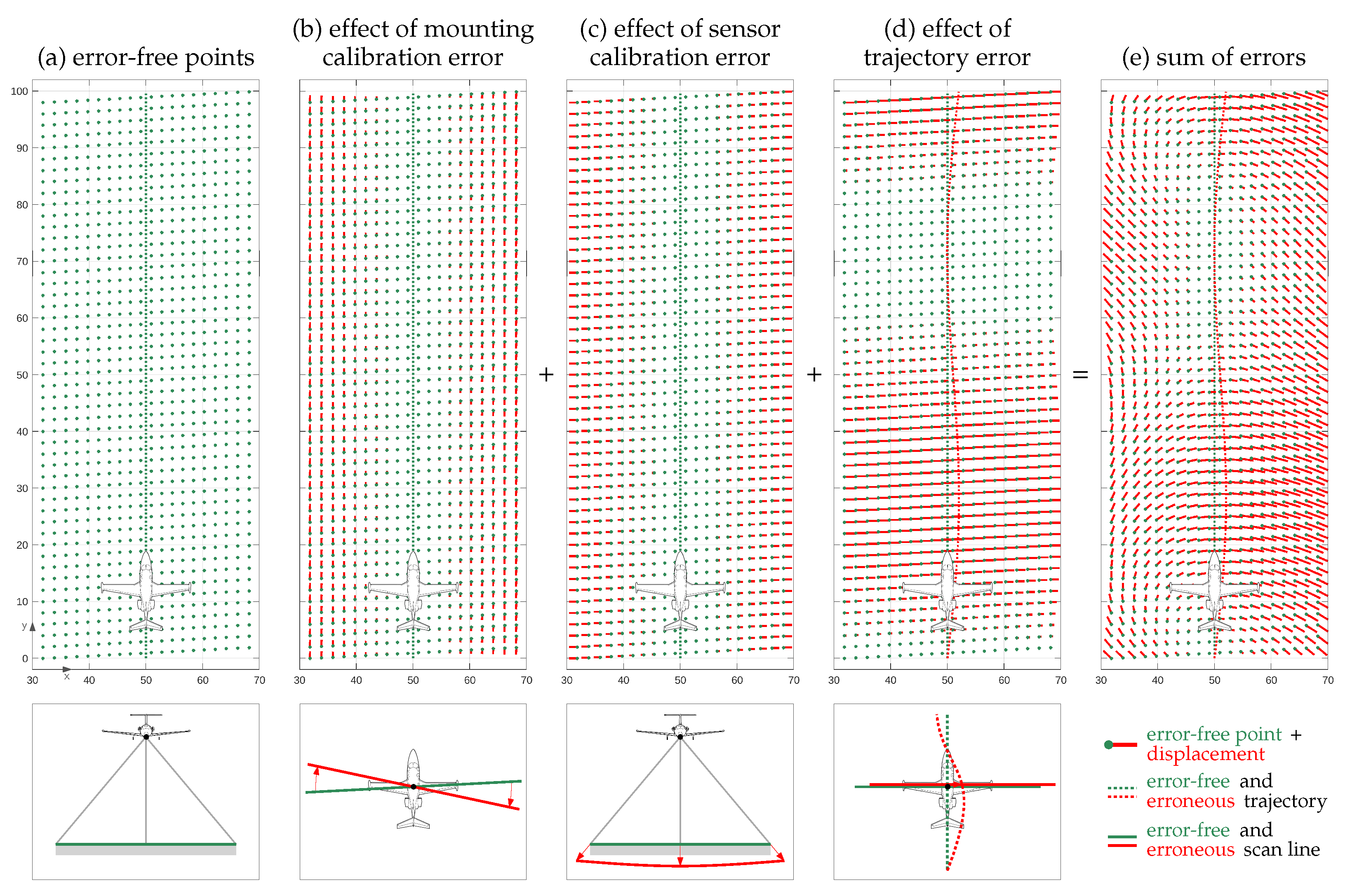
- Approximative vs. rigorous: Most registration algorithms are approximative in the sense that they use the 2D or 3D point coordinates as inputs only and try to minimize discrepancies across overlapping point clouds by applying a rather simple and general (rigid or nonrigid) transformation model. Ref. [21] describes this group of algorithms as rubber-sheeting coregistration solutions. In contrast, rigorous solutions try to model the point cloud generation process as accurately as possible by going a step backwards and using the sensor’s raw measurements. The main advantage of such methods is that point cloud discrepancies are corrected at their source, e.g., by sensor self-calibration of a miscalibrated lidar sensor [22]. Rigorous solutions are especially important in case of point clouds captured from moving platforms, e.g., robots, vehicles, drones, airplanes, helicopters, or satellites. In a minimal configuration, such methods simultaneously register overlapping point clouds and estimate the trajectory of the platform. More sophisticated methods additionally estimate intrinsic and extrinsic sensor calibration parameters and/or consider ground truth data, e.g., ground control points (GCPs), to improve the georeference of the point clouds. If point clouds need to be generated online, e.g., in robotics, this type of problem is addressed by SLAM (simultaneous localization and mapping), and especially lidar SLAM [23] and visual-lidar SLAM [24] methods. For offline point cloud generation, however, methods are often summarized under the term (rigorous) strip adjustment, as the continuous platform’s trajectory is often divided into individual strips for easier data handling—an overview can be found in [21,25].
1.2. Motivation for Nonrigid Transformations
1.3. Main Contributions
1.4. Structure of the Paper
2. The Point Cloud Registration Problem
Extension to Nonrigid Transformations
3. Related Work in the Context of Nonrigid Point Cloud Registration
3.1. Continuity Model
- Physically based models: These models use some kind of physical analogy to model nonrigid distortions. They are typically defined by partial differential equations of continuum mechanics. Specifically, they are mostly based on the theory of linear elasticity (e.g., [45]), the theory of motion coherence (e.g., [18,27]), the theory of fluid flow (e.g., [46]), or similarly, the theory of optical flow (e.g., [47]).
- Models based on interpolation and approximation theory: These models are purely data driven and typically use basis function expansion to model the transformation field . For this, some sort of piecewise polynomial functions with a degree ≤ 3 are widely used, e.g., radial basis functions, thin-plate splines (e.g., [26]), B-splines (e.g., [48]), or wavelets. Other methods use simply a weighted mean interpolation (e.g., [41,49,50,51]), penalize changes of the parameter vector (e.g., [52]) or the translation vector (e.g., [53,54,55]) with increasing distance, or try to preserve the length of neighboring points (e.g., [56]).
3.2. Local Transformation Model
- Local translation (; linear model): This is the simplest and most intuitive model: the transformation is defined at each position by an individual translation vector (). Accordingly, Equation (14) simplifies to the trivial formand the transformation parameters directly correspond to .An example is the coherent point drift (CPD) algorithm, a rather popular solution introduced by [18]. It is available in several programs, e.g., PDAL (http://pdal.io, accessed on 10 October 2023) or Matlab (function pcregistercpd). The transformation model is based on the motion coherence theory [57]. Accordingly, the translations applied to the loose point cloud are modeled as a temporal motion process. The displacement field is thereby estimated as a continuous velocity field, whereby a motion coherence constraint ensures that points close to one another tend to move coherently. A modern interpretation of the CPD algorithm with several enhancements was recently published by [27]. Another widely used algorithm in this category was published by [26]. The transformation model is thereby based on the above-mentioned thin-plate splines (TPS), a mechanical analogy referring to the bending of thin sheets of metal. In our context of point cloud registration, the authors interpret the bending as the displacement of the transformed points w.r.t. to their original position. The TPS transformation model ensures the continuity of the transformation values. Large local oscillations of these values are avoided by minimizing the bending energy, i.e., by penalizing the second derivatives of the transformation surface (in 2D) or volume (in 3D).The local translation model offers the highest level of flexibility as it does not couple the transformation to any kind of geometrical constraint. However, this flexibility comes also with the risk of un-natural local shape deformations due to overfitting, especially in cases where the transformation field has a very flexible control structure.
- Local rigid-body transformation (; nonlinear model): The transformation at each point is defined by an individual set of rigid-body transformation parameters . In the 3D case, is composed of three rotation angles, , , and , and the translation vector (), and the translation becomesThe open-source solution by [41] uses a graph-based transformation field, where each node has an associated individual rigid-body transformation; the transformation values between these nodes are determined by interpolation. A similar graph-based approach used for motion reconstruction is described in [45,55]. The authors of [50] first segment the point cloud into rigid clusters and then map an individual rigid-body transformation to each of these segments.Generally, the advantage of a rigid-body transformation field—especially in comparison with the less restricted translation field—is that it implicitly guarantees local shape preservation and needs less correspondences due to geometrical constraints implicitly added by the transformation model. The main disadvantages, however, are the nonlinearity of the model due to the involved rotations and the larger number of unknown parameters in the optimization.
- Local affine transformation (; linear model): This is the most commonly used model in the literature. The transformation at each point is defined by an individual set of affine transformation parameters :where is composed of the vectors (holding the elements of the affine matrix ) and the translation vector .A popular early example of an affine-based transformation field is presented by [52]. Ref. [49] proposes a graph-based transformation field, where each node corresponds to an individual affine transformation. To avoid un-natural local shearing, they use additional regularization terms, which ensure that the transformation is locally “as-rigid-as-possible”. Specifically, additional condition equations are added to the optimization so that the matrix A is “as-orthogonal-as-possible”, i.e., so that it is very close to an orthogonal rotation matrix. Ref. [53] additionally allows a local scaling of the point cloud by constraining the local affine transformation to a similarity transformation in an “as-conformal-as-possible” approach.In terms of flexibility, the affine transformation lies between the local translation model (more flexible) and the rigid-body transformation model (less flexible). An important advantage compared with the rigid-body transformation is the linearity of the model. However, the linearity often gets lost by the introduction of additional nonlinear equations, e.g., for local rigidity or local conformity. This model leads in comparison with the ones discussed above to the highest number of unknown parameters in the optimization.
3.3. Control Structure
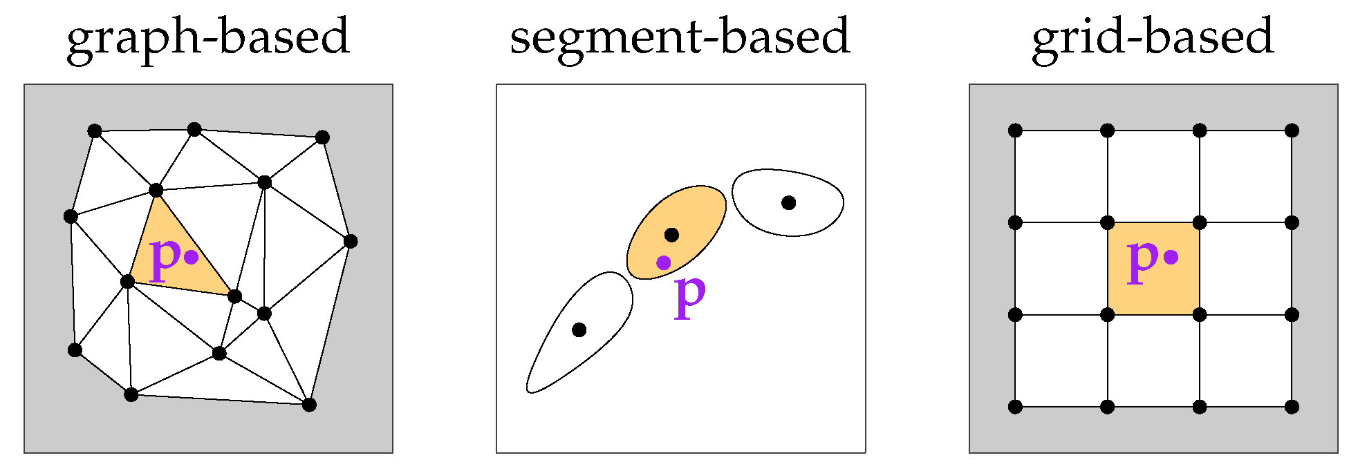
- Graph-based: This is the most commonly used control structure. The graph for a transformation field is typically constructed by selecting a subset of the observed points as nodes, e.g., by using a random or uniform sampling approach [3]. Consequently, the nodes lie directly on the scanned objects. Nodes are typically connected by undirected edges, which indicate local object connectivities. The flexibility of the transformation field can be adjusted by the density of the nodes.In the context of nonrigid deformation of moving characters, a widely used and highly efficient subsampling algorithm was introduced in [59]—it was also used in [49] to obtain evenly distributed nodes over the entire object. Ref. [55] extended the concept of graph-based structures to a double-layer graph, where the inner layer was used to model the human skeleton and the outer layer was used to model the deformations of the observed surface regions. Ref. [41] defined the nodes by subsampling the point cloud with a voxel-based uniform sampling method.Considering that graph-based control structures are tightly bound to the observed objects (e.g., humans or animals), they can be regarded as best suited in cases where transformations should model the movement (deformation) of these objects. On the downside, this concept is difficult to adopt to large scenes that include multiple heterogeneous objects and complex geometries (e.g., vegetation). For example, in lidar-based remote sensing, point clouds of relatively large areas (of up to hundreds of square kilometers) that include many very different objects (buildings, vegetation, cars, persons, etc.) are acquired. In such cases, the proper definition of a graph-based control structure is rather difficult.
- Segment based: Such methods split the point clouds in multiple segments and estimate an individual transformation (often a rigid-body transformation under the assumption of local rigidity) for each segment. A frequent application is the matching of human scans where individual segments correspond to, e.g., upper arms, forearms, upper legs, and shanks.Ref. [60] determines such segments under the assumption of an isometric (distance-preserving) deformation and predetermined correspondences using the RANSAC framework. Ref. [56] additionally blends the transformations between two adjacent segments in the overlapping region to preserve the consistency of the shape. A similar approach was presented in [50]; however, global consistency is achieved here by defining the final transformation of a point as a weighted sum of the individual segment transformations, whereby the weights decrease with growing segment distances.An advantage of this type of methods is a relatively low DoF, which lowers the risk of overfitting and processing time. A major limitation, however, is that the point clouds to be registered must be divisible into multiple rigid segments. In this sense, their usability is also not very versatile.
- Grid based: These methods use regularly or irregularly spaced grids as a control structure of . The flexibility of the control structure can be easily influenced by the grid spacing.An early work using a hierarchical grid-based control structure that is based on an octree is described in [48]—deformations are thereby modeled by volumetric B-splines. Ref. [51] discretizes the object space in a regular 3D grid, i.e., a voxel grid. A local rigid-body transformation is associated with each grid point. Transformation parameter values between the grid points are obtained via trilinear interpolation. Ref. [54] also used a voxel grid in combination with local rigid-body transformations; however, the transformation values at the voxel resolution are obtained by interpolating transformations of an underlying sparse graph-based structure—this way, the number of unknown parameters can drastically be reduced, which in turn allows for an efficient estimation of the transformation field.A regularly spaced grid-based control structure is typically object independent; i.e., the grid structure is not influenced by the type of objects that are in the scene. In this sense, it is a much more general choice compared with the two control structures discussed above, which are mostly tailored to specific use cases or specific measurement setups. Consequently, a grid-based structure seems also to be a natural choice for large, complex, multiobject scenes, e.g., for large lidar point clouds. Another relating advantage is that it is easier to control the domain of —for example, the domain can be easily set to a precisely defined 3D bounding box of the observed scene.
4. Method
4.1. The Nonrigid Transformation Model
- Continuity: The transformation field is and continuous; i.e., transformation values change smoothly over the entire voxel structure.
- Flexibility: The domain of corresponds to the extents of the voxel structure. Thus, it can easily be defined by the user, e.g., to match exactly the extents of point cloud tiles. Moreover, the resolution of can easily be adjusted through the voxel size.
- Efficiency: The transformation field can efficiently be estimated for two reasons. First, the number of unknown parameters is relatively low. Second, the transformation is a linear function of the parameters in . In other words, the parameters of can be estimated through a closed-form solution that does not require an iterative solution or initial values for the parameters. Moreover, the transformation of very large point clouds can efficiently be implemented using Equation (31).
- Intuitivity: The parameters of the transformation field can easily be interpreted as they directly correspond to the translation values and the derivatives. Thus, it is also rather easy to manipulate these parameters by introducing additional parameter observations, constraints, or upper limits to the optimization.
4.2. Regularization
- To solve an ill-posed or ill-conditioned problem. Our problem becomes ill posed (underdetermined) if the domain of , i.e., the voxel structure, contains areas with too few or even no correspondences. As a consequence, a subset of the unknown parameters cannot be estimated. Relatedly, the problem can be ill conditioned (indicated by a high condition number C of the equation system) if the correspondences have locally an unfavorable geometrical constellation; for example, the scalar fields and can hardly be estimated when matching two nearly horizontal planes. By regularization, an ill-posed or ill-conditioned problem can be transformed into a well-posed and well-conditioned problem.
- To control the smoothness of the transformation field and thereby also prevent overfitting. The smoothness of is controlled by directly manipulating the unknown parameters, i.e., the function values and the derivatives at the voxel corners. Simultaneously, overfitting can also be avoided, i.e., the suppression of excessively fluctuating values of the scalar fields , , and .
4.3. A Synthetic 2D Example
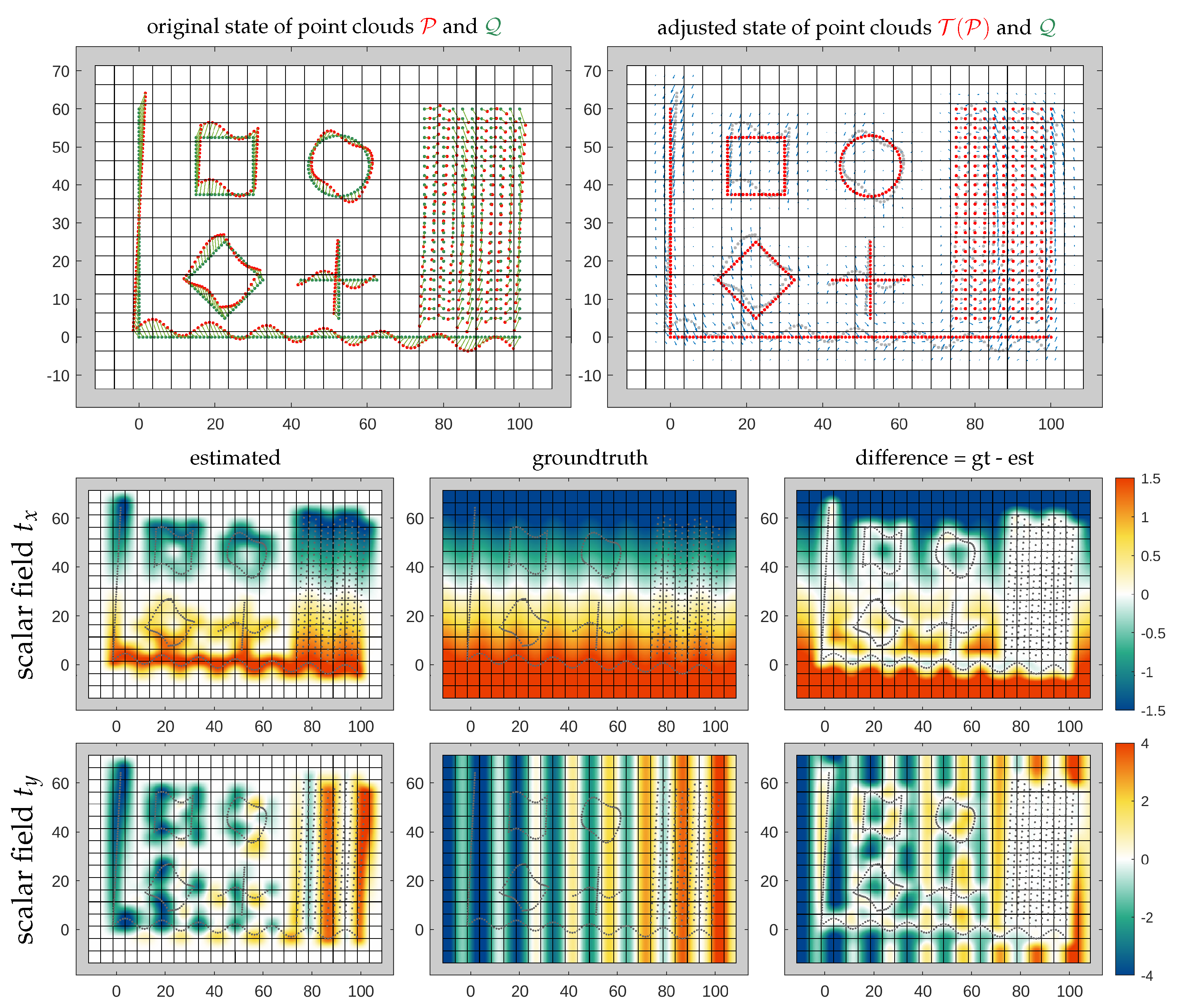
- In areas with dense correspondences, the transformation can be well estimated; i.e., the differences between the estimated scalar fields and their ground truth fields are nearly zero in these areas. In correspondence-free areas the transformation tends towards zero due to a lack of information.
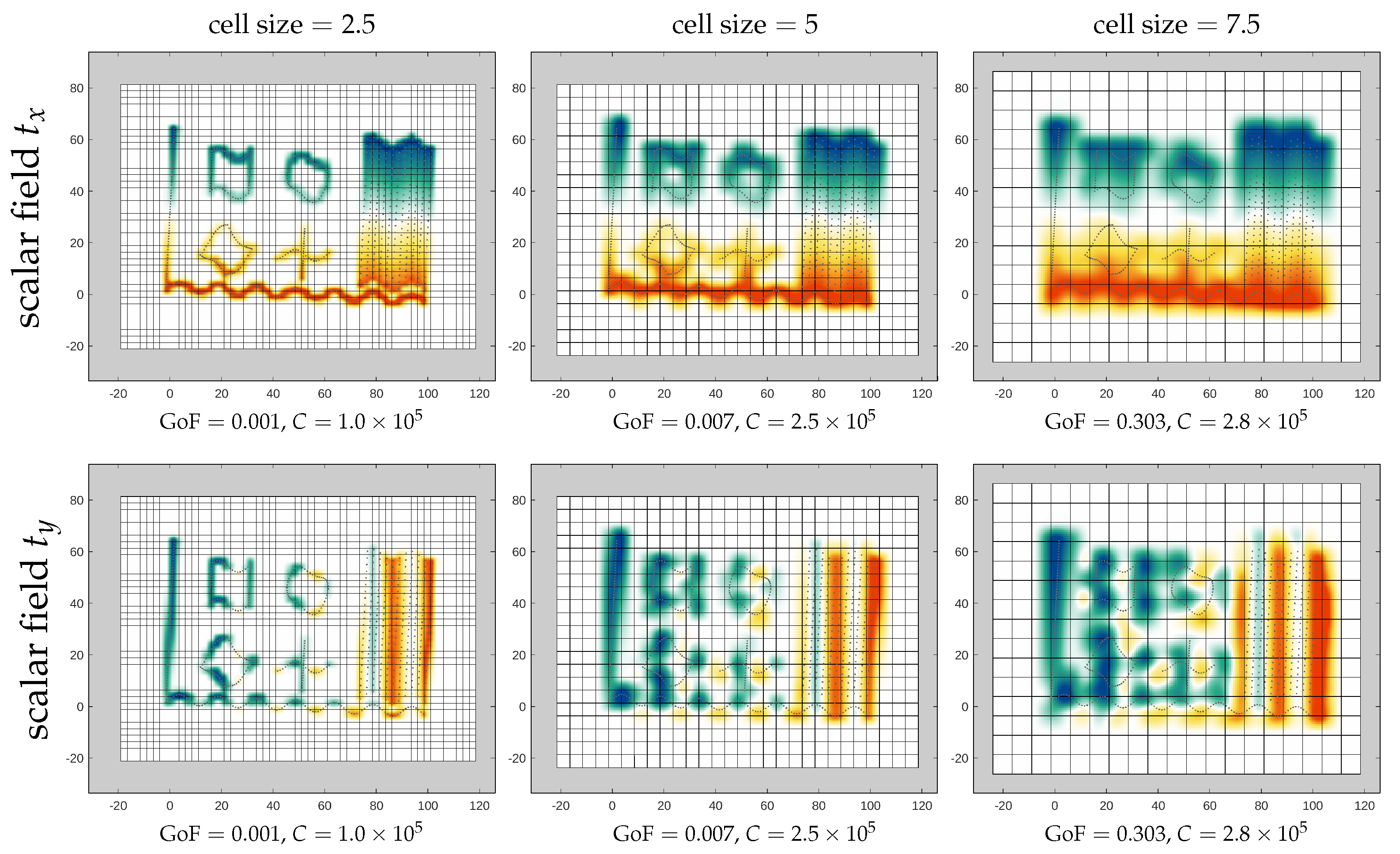
- The locality of the transformation depends mainly on the cell size. Minor adjustments of the locality can be made by modifying the weight . The cell size needs to be adjusted to the variability of the transformation to be modeled.
- The scalar fields tend to oscillate if the ratio is large—in such cases, the scalar fields have relatively steep slopes at the cell corners.
- The GoF is better for lower weights and smaller cell sizes. However, in case of correspondences with even small random errors, a small cell size also increases the risk of overfitting.
- The condition number C decreases with higher weights; i.e., the stability and efficiency of the parameter estimation increase.
5. Implementation Details
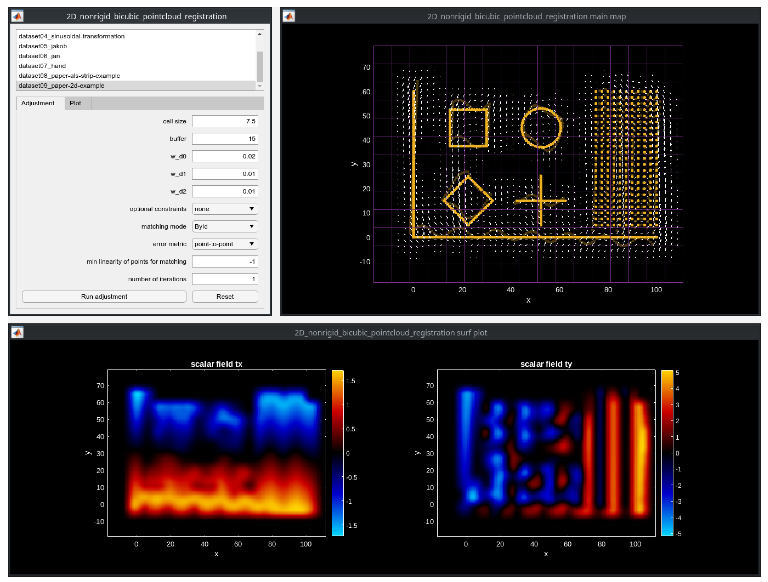
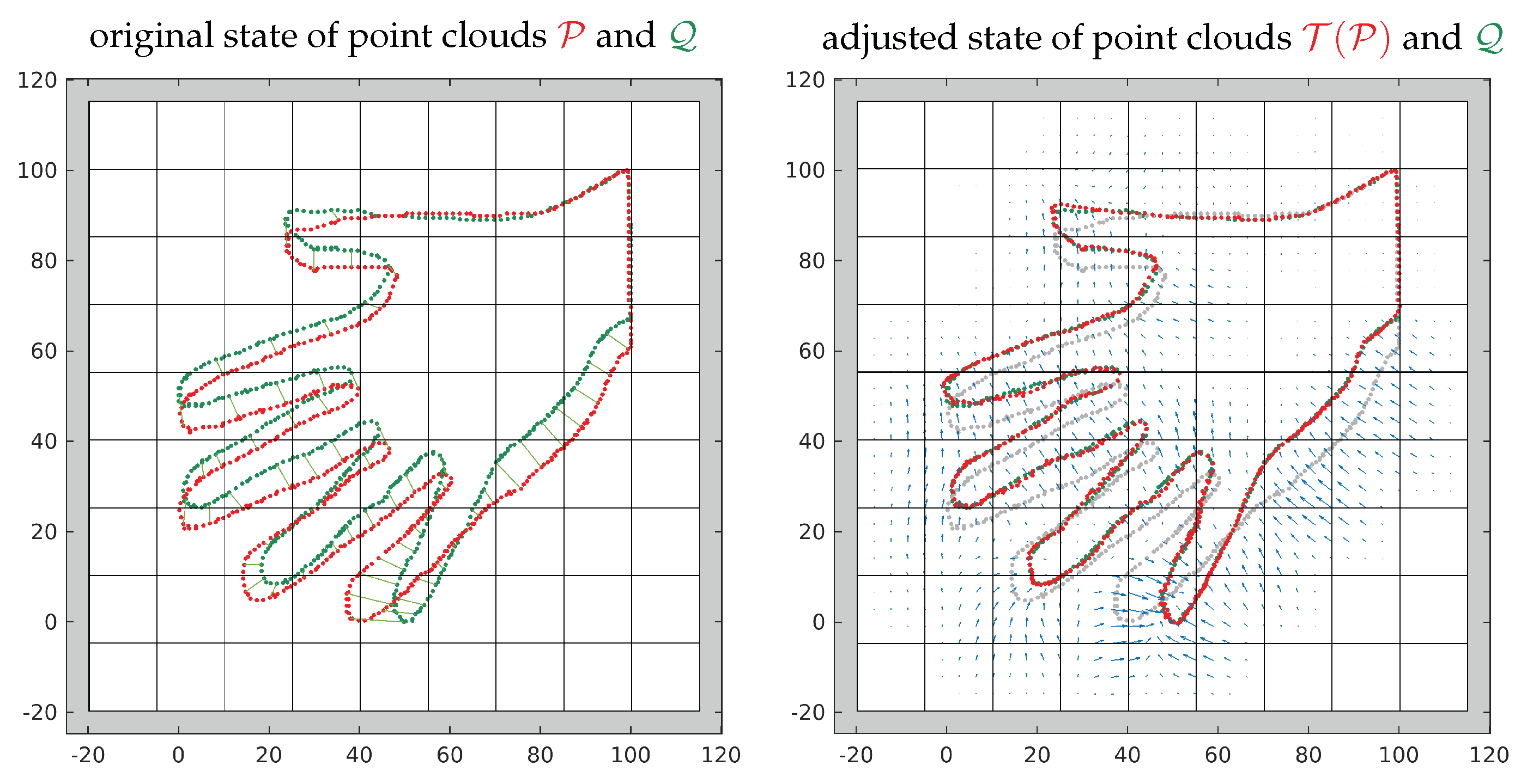
- Matlab (2D): This is an open-source prototype implementation for two-dimensional point clouds (Figure 10). It can be downloaded here: https://github.com/AIT-Assistive-Autonomous-Systems/2D_nonrigid_tricubic_pointcloud_registration (accessed on 10 October 2023). Parameters can easily be modified through a graphical user interface (GUI). The least squares problem is defined using the problem-based optimization setup from the Optimization Toolbox; thereby, all matrix and vector operations are vectorized for efficiency reasons. The problem is solved using the linear least squares solver lsqlin. In addition to the Optimization Toolbox, the Statistics and Machine Learning Toolbox is required to run the code. As a reference, solving the optimization for the example depicted in Figure 10 takes approximately 0.4 s on a regular PC (CPU Intel Core i7-10850H).
- C++/Python (3D): This is a highly efficient implementation of our method for large (e.g., lidar-based) three-dimensional point clouds. It can be downloaded here: https://github.com/AIT-Assistive-Autonomous-Systems/3D_nonrigid_tricubic_pointcloud_registration (accessed on 10 October 2023). The full processing pipeline is managed by a Python script and consists of three main steps. In the first step, the loose point cloud and the fixed point cloud are preprocessed using PDAL (https://pdal.io, accessed on 10 October 2023); the preprocessing includes mainly a filtering of the point clouds and the normal vector estimation. In the second step, a C++ implementation of the registration pipeline depicted in Figure 2 is used to estimate the transformation field by matching the preprocessed point clouds. Thereby, the main C++ dependencies are Eigen (https://eigen.tuxfamily.org, accessed on 10 October 2023) and nanoflann (https://github.com/jlblancoc/nanoflann, accessed on 10 October 2023). Eigen is used for all linear algebra operations and for setting up and solving the optimization problem. A benchmark has shown that the biconjugate gradient stabilized solver (BiCGSTAB) is the most efficient solver for our type of problem. Finally, in the third step, the estimated transformation is applied to the original point cloud . As a reference, the estimation of the transformation field for the point clouds in Section 6.4 takes approximately 10 s, again on the regular PC mentioned above.
6. Experimental Results
6.1. Use Case 1: Airborne Laser Scanning (ALS)—Alignment of Historical Data
6.2. Use Case 2: Airborne Laser Scanning (ALS)—Post-Strip-Adjustment Refinement
6.3. Use Case 3: Low-Cost Mobile Laser Scanning (MLS)
6.4. Use Case 4: Terrestrial Laser Scanning (TLS)
6.5. Use Case 5: Dense Optical Flow
6.6. Use Case 6: Popular Datasets
7. Conclusions
Author Contributions
Funding
Data Availability Statement
Acknowledgments
Conflicts of Interest
Nomenclature
| Notation | |||
| Symbol(s) | Description | Type | Dim. |
| Point cloud registration | |||
| loose and fixed set of points (point clouds), resp. | set | , | |
| individual point of point cloud and , resp. | vector | ||
| transformation of point cloud and point , resp. | func. | ||
| transformed point cloud | set | ||
| transformed point | vector | ||
| translation vector | vector | ||
| normal vector | vector | ||
| set of correspondences between and | set | ||
| set of weights associated with | set | ||
| individual weight of | scalar | ||
| transformation field | func. | ||
| f | continuity model | func. | |
| g | local transformation model | func. | |
| vector containing transformation parameters | vector | ||
| Optimization | |||
| overall number of unknown parameters | scalar | ||
| E | error term of objective function | scalar | |
| C | condition number of equation system | scalar | |
| Piecewise tricubic polynomials | |||
| reduced and normalized coordinates of point | vector | ||
| vector containing coefficients of single voxel | vector | ||
| vector containing function values and derivatives of single voxel | vector | ||
| matrix for mapping between and | matrix | ||
| vector containing products of | vector | ||
| matrix containing products of for points | matrix | ||
| voxel origin | vector | ||
| s | voxel size | scalar | |
References
- Besl, P.J.; McKay, N.D. Method for registration of 3-D shapes. In Robotics-DL Tentative; International Society for Optics and Photonics: Bellingham, WA, USA, 1992; pp. 586–606. [Google Scholar]
- Chen, Y.; Medioni, G. Object modelling by registration of multiple range images. Image Vis. Comput. 1992, 10, 145–155. [Google Scholar] [CrossRef]
- Glira, P.; Pfeifer, N.; Briese, C.; Ressl, C. A Correspondence Framework for ALS Strip Adjustments based on Variants of the ICP Algorithm. PFG Photogramm. Fernerkund. Geoinf. 2015, 2015, 275–289. [Google Scholar] [CrossRef]
- Rusinkiewicz, S.; Levoy, M. Efficient variants of the ICP algorithm. In Proceedings of the Third International Conference on 3-D Digital Imaging and Modeling, Quebec City, QC, Canada, 28 May–1 June 2001; pp. 145–152. [Google Scholar]
- Pomerleau, F.; Colas, F.; Siegwart, R. A review of point cloud registration algorithms for mobile robotics. Found. Trends Robot. 2015, 4, 1–104. [Google Scholar] [CrossRef]
- Dong, Z.; Liang, F.; Yang, B.; Xu, Y.; Zang, Y.; Li, J.; Wang, Y.; Dai, W.; Fan, H.; Hyyppä, J.; et al. Registration of large-scale terrestrial laser scanner point clouds: A review and benchmark. ISPRS J. Photogramm. Remote. Sens. 2020, 163, 327–342. [Google Scholar] [CrossRef]
- Huang, S.; Gojcic, Z.; Usvyatsov, M.; Wieser, A.; Schindler, K. Predator: Registration of 3D point clouds with low overlap. In Proceedings of the IEEE/CVF Conference on Computer Vision and Pattern Recognition, Nashville, TN, USA, 20–25 June 2021; pp. 4267–4276. [Google Scholar]
- Li, L.; Wang, R.; Zhang, X. A tutorial review on point cloud registrations: Principle, classification, comparison, and technology challenges. Math. Probl. Eng. 2021, 2021, 9953910. [Google Scholar] [CrossRef]
- Yang, J.; Li, H.; Campbell, D.; Jia, Y. Go-ICP: A globally optimal solution to 3D ICP point-set registration. IEEE Trans. Pattern Anal. Mach. Intell. 2015, 38, 2241–2254. [Google Scholar] [CrossRef] [PubMed]
- Zeng, A.; Song, S.; Nießner, M.; Fisher, M.; Xiao, J.; Funkhouser, T. 3DMatch: Learning Local Geometric Descriptors from RGB-D Reconstructions. In Proceedings of the 2017 IEEE Conference on Computer Vision and Pattern Recognition (CVPR), Honolulu, HI, USA, 21–26 July 2017. [Google Scholar]
- Zhang, Z.; Dai, Y.; Sun, J. Deep learning based point cloud registration: An overview. Virtual Real. Intell. Hardw. 2020, 2, 222–246. [Google Scholar] [CrossRef]
- Gu, X.; Wang, Y.; Wu, C.; Lee, Y.J.; Wang, P. HPLFlowNet: Hierarchical Permutohedral Lattice FlowNet for Scene Flow Estimation on Large-scale Point Clouds. In Proceedings of the 2019 IEEE International Conference on Computer Vision and Pattern Recognition (CVPR), Long Beach, CA, USA, 15–20 June 2019. [Google Scholar]
- Liu, X.; Qi, C.R.; Guibas, L.J. FlowNet3D: Learning Scene Flow in 3D Point Clouds. In Proceedings of the 2019 IEEE/CVF Conference on Computer Vision and Pattern Recognition (CVPR), Long Beach, CA, USA, 15–20 June 2019; pp. 529–537. [Google Scholar] [CrossRef]
- Glira, P.; Pfeifer, N.; Briese, C.; Ressl, C. Rigorous Strip Adjustment of Airborne Laserscanning Data Based on the ICP Algorithm. ISPRS Ann. Photogramm. Remote. Sens. Spat. Inf. Sci. 2015, II-3/W5, 73–80. [Google Scholar] [CrossRef]
- Theiler, P.W.; Wegner, J.D.; Schindler, K. Globally consistent registration of terrestrial laser scans via graph optimization. ISPRS J. Photogramm. Remote. Sens. 2015, 109, 126–138. [Google Scholar] [CrossRef]
- Brown, B.; Rusinkiewicz, S. Global Non-Rigid Alignment of 3-D Scans. ACM Trans. Graph. 2007, 26, 1–9. [Google Scholar] [CrossRef]
- Ressl, C.; Pfeifer, N.; Mandlburger, G. Applying 3D affine transformation and least squares matching for airborne laser scanning strips adjustment without GNSS/IMU trajectory data. In Proceedings of the ISPRS Workshop Laser Scanning 2011, Calgary, Canada, 29–31 August 2011. [Google Scholar]
- Myronenko, A.; Song, X.; Carreira-Perpinan, M. Non-rigid point set registration: Coherent point drift. Adv. Neural Inf. Process. Syst. 2006, 19, 1009–1016. [Google Scholar]
- Liang, L.; Wei, M.; Szymczak, A.; Petrella, A.; Xie, H.; Qin, J.; Wang, J.; Wang, F.L. Nonrigid iterative closest points for registration of 3D biomedical surfaces. Opt. Lasers Eng. 2018, 100, 141–154. [Google Scholar] [CrossRef]
- Qin, Z.; Yu, H.; Wang, C.; Guo, Y.; Peng, Y.; Xu, K. Geometric Transformer for Fast and Robust Point Cloud Registration. arXiv 2022. [Google Scholar] [CrossRef]
- Toth, C.K. Strip Adjustment and Registration. In Topographic Laser Ranging and Scanning-Principles and Processing; Shan, J., Toth, C.K., Eds.; CRC Press: Boca Raton, FL, USA, 2009; pp. 235–268. [Google Scholar]
- Lichti, D.D. Error modelling, calibration and analysis of an AM–CW terrestrial laser scanner system. ISPRS J. Photogramm. Remote. Sens. 2007, 61, 307–324. [Google Scholar] [CrossRef]
- Hess, W.; Kohler, D.; Rapp, H.; Andor, D. Real-time loop closure in 2D LIDAR SLAM. In Proceedings of the 2016 IEEE International Conference on Robotics and Automation (ICRA), Stockholm, Sweden, 16–21 May 2016; pp. 1271–1278. [Google Scholar]
- Zhang, J.; Singh, S. Visual-lidar odometry and mapping: Low-drift, robust, and fast. In Proceedings of the 2015 IEEE International Conference on Robotics and Automation (ICRA), Seattle, WA, USA, 26–30 May 2015; pp. 2174–2181. [Google Scholar]
- Glira, P. Hybrid Orientation of LiDAR Point Clouds and Aerial Images. PhD Thesis, TU Wien, Vienna, Austria, 2018. [Google Scholar]
- Chui, H.; Rangarajan, A. A new point matching algorithm for non-rigid registration. Comput. Vis. Image Underst. 2003, 89, 114–141. [Google Scholar] [CrossRef]
- Fan, A.; Ma, J.; Tian, X.; Mei, X.; Liu, W. Coherent Point Drift Revisited for Non-Rigid Shape Matching and Registration. In Proceedings of the IEEE/CVF Conference on Computer Vision and Pattern Recognition (CVPR), New Orleans, LA, USA, 18–24 June 2022; pp. 1424–1434. [Google Scholar]
- Keszei, A.P.; Berkels, B.; Deserno, T.M. Survey of non-rigid registration tools in medicine. J. Digit. Imaging 2017, 30, 102–116. [Google Scholar] [CrossRef] [PubMed]
- Dai, M.; Xiao, G.; Fiondella, L.; Shao, M.; Zhang, Y.S. Deep Learning-Enabled Resolution-Enhancement in Mini- and Regular Microscopy for Biomedical Imaging. Sens. Actuators A Phys. 2021, 331, 112928. [Google Scholar] [CrossRef] [PubMed]
- Ressl, C.; Kager, H.; Mandlburger, G. Quality Checking of ALS Projects using Statistics of Strip Differences. In Proceedings of the International Society for Photogrammetry and Remote Sensing 21st Congress, Beijing, China, 3–7 July 2008; Volume XXXVII, Part B3b. pp. 253–260. [Google Scholar]
- Glira, P.; Pfeifer, N.; Mandlburger, G. Rigorous Strip adjustment of UAV-based laserscanning data including time-dependent correction of trajectory errors. Photogramm. Eng. Remote. Sens. 2016, 82, 945–954. [Google Scholar] [CrossRef]
- Glira, P.; Pfeifer, N.; Mandlburger, G. Hybrid Orientation of Airborne Lidar Point Clouds and Aerial Images. ISPRS Ann. Photogramm. Remote. Sens. Spat. Inf. Sci. 2019, 4, 567–574. [Google Scholar] [CrossRef]
- Glennie, C. Rigorous 3D error analysis of kinematic scanning LIDAR systems. J. Appl. Geod. 2007, 1, 147–157. [Google Scholar] [CrossRef]
- Habib, A.; Rens, J. Quality assurance and quality control of Lidar systems and derived data. In Proceedings of the Advanced Lidar Workshop, University of Northern Iowa, Cedar Falls, IA, USA, 7–8 August 2007. [Google Scholar]
- Kager, H. Discrepancies between overlapping laser scanner strips–simultaneous fitting of aerial laser scanner strips. Int. Arch. Photogramm. Remote. Sens. Spat. Inf. Sci. 2004, 35, 555–560. [Google Scholar]
- Filin, S.; Vosselman, G. Adjustment of airborne laser altimetry strips. ISPRS Arch. Photogramm. Remote. Sens. Spat. Inf. Sci. 2004, XXXV, B3. [Google Scholar]
- Ressl, C.; Mandlburger, G.; Pfeifer, N. Investigating adjustment of airborne laser scanning strips without usage of GNSS/IMU trajectory data. Int. Arch. Photogramm. Remote. Sens. Spat. Inf. Sci. 2009, 38, 195–200. [Google Scholar]
- Csanyi, N.; Toth, C.K. Improvement of lidar data accuracy using lidar-specific ground targets. Photogramm. Eng. Remote. Sens. 2007, 73, 385–396. [Google Scholar] [CrossRef]
- Vosselman, G.; Maas, H.G. Adjustment and Filtering of Raw Laser Altimetry Data. In Proceedings of the OEEPE Workshop on Airborne Laserscanning and Interferometric SAR for Detailed Digital Terrain Models, Stockholm, Sweden, 1–3 March 2001. [Google Scholar]
- Förstner, W.; Wrobel, B. Photogrammetric Computer Vision—Statistics, Geometry, Orientation and Reconstruction; Springer: Berlin/Heidelberg, Germany, 2016. [Google Scholar] [CrossRef]
- Zampogiannis, K.; Fermüller, C.; Aloimonos, Y. Topology-Aware Non-Rigid Point Cloud Registration. IEEE Trans. Pattern Anal. Mach. Intell. 2021, 43, 1056–1069. [Google Scholar] [CrossRef] [PubMed]
- Tam, G.K.; Cheng, Z.Q.; Lai, Y.K.; Langbein, F.C.; Liu, Y.; Marshall, D.; Martin, R.R.; Sun, X.F.; Rosin, P.L. Registration of 3D Point Clouds and Meshes: A Survey from Rigid to Nonrigid. IEEE Trans. Vis. Comput. Graph. 2013, 19, 1199–1217. [Google Scholar] [CrossRef] [PubMed]
- Deng, B.; Yao, Y.; Dyke, R.M.; Zhang, J. A Survey of Non-Rigid 3D Registration. Comput. Graph. Forum 2022, 41, 559–589. [Google Scholar] [CrossRef]
- Holden, M. A review of geometric transformations for nonrigid body registration. IEEE Trans. Med. Imaging 2007, 27, 111–128. [Google Scholar] [CrossRef]
- Li, W.; Zhao, S.; Xiao, X.; Hahn, J.K. Robust Template-Based Non-Rigid Motion Tracking Using Local Coordinate Regularization. In Proceedings of the 2020 IEEE Winter Conference on Applications of Computer Vision (WACV), Snowmass, CO, USA, 1–5 March 2020; pp. 390–399. [Google Scholar]
- Christensen, G.E.; Rabbitt, R.D.; Miller, M.I. 3D brain mapping using a deformable neuroanatomy. Phys. Med. Biol. 1994, 39, 609–618. [Google Scholar] [CrossRef]
- Thirion, J.P. Image matching as a diffusion process: An analogy with Maxwell’s demons. Med. Image Anal. 1998, 2, 243–260. [Google Scholar] [CrossRef]
- Szeliski, R.; Lavallée, S. Matching 3-D anatomical surfaces with non-rigid deformations using octree-splines. Int. J. Comput. Vis. 1994, 18, 171–186. [Google Scholar] [CrossRef]
- Sumner, R.W.; Schmid, J.; Pauly, M. Embedded deformation for shape manipulation. ACM Trans. Graph. 2007, 26, 80–88. [Google Scholar] [CrossRef]
- Huang, Q.X.; Adams, B.; Wicke, M.; Guibas, L.J. Non-Rigid Registration Under Isometric Deformations. Comput. Graph. Forum 2008, 27, 1449–1457. [Google Scholar] [CrossRef]
- Innmann, M.; Zollhöfer, M.; Nießner, M.; Theobalt, C.; Stamminger, M. VolumeDeform: Real-Time Volumetric Non-rigid Reconstruction. arXiv 2016, arXiv:1603.08161. [Google Scholar] [CrossRef]
- Allen, B.; Curless, B.; Popovic, Z. The space of human body shapes: Reconstruction and parameterization from range scans. ACM Trans. Graph. 2003, 22, 587–594. [Google Scholar] [CrossRef]
- Yoshiyasu, Y.; Ma, W.C.; Yoshida, E.; Kanehiro, F. As-Conformal-As-Possible Surface Registration. Comput. Graph. Forum 2014, 33, 1–11. [Google Scholar] [CrossRef]
- Newcombe, R.A.; Fox, D.; Seitz, S.M. DynamicFusion: Reconstruction and tracking of non-rigid scenes in real-time. In Proceedings of the 2015 IEEE Conference on Computer Vision and Pattern Recognition (CVPR), Boston, MA, USA, 7–12 June 2015; pp. 343–352. [Google Scholar]
- Yu, T.; Zheng, Z.; Guo, K.; Zhao, J.; Dai, Q.; Li, H.; Pons-Moll, G.; Liu, Y. DoubleFusion: Real-Time Capture of Human Performances with Inner Body Shapes from a Single Depth Sensor. In Proceedings of the 2018 IEEE/CVF Conference on Computer Vision and Pattern Recognition, Salt Lake City, UT, USA, 18–23 June 2018; pp. 7287–7296. [Google Scholar]
- Chang, W.; Zwicker, M. Automatic Registration for Articulated Shapes. Comput. Graph. Forum 2008, 27, 1459–1468. [Google Scholar] [CrossRef]
- Yuille, A.; Grzywacz, N. The Motion Coherence Theory. In Proceedings of the 1988 Second International Conference on Computer Vision, Tampa, FL, USA, 5–8 December 1988; pp. 344–353. [Google Scholar] [CrossRef]
- Yamazaki, S.; Kagami, S.; Mochimaru, M. Non-rigid Shape Registration Using Similarity-Invariant Differential Coordinates. In Proceedings of the 2013 International Conference on 3D Vision, Seattle, WA, USA, 29 June–1 July, 2013; pp. 191–198. [Google Scholar]
- Mohr, A.; Gleicher, M. Building efficient, accurate character skins from examples. ACM Trans. Graph. 2003, 22, 562–568. [Google Scholar] [CrossRef]
- Ge, X. Non-rigid registration of 3D point clouds under isometric deformation. ISPRS J. Photogramm. Remote. Sens. 2016, 121, 192–202. [Google Scholar] [CrossRef]
- Lekien, F.; Marsden, J. Tricubic interpolation in three dimensions. Int. J. Numer. Methods Eng. 2005, 63, 455–471. [Google Scholar] [CrossRef]
- Calvetti, D.; Reichel, L. Tikhonov regularization of large linear problems. BIT Numer. Math. 2003, 43, 263–283. [Google Scholar] [CrossRef]
- Mandlburger, G.; Hauer, C.; Wieser, M.; Pfeifer, N. Topo-Bathymetric LiDAR for Monitoring River Morphodynamics and Instream Habitats—A Case Study at the Pielach River. Remote. Sens. 2015, 7, 6160–6195. [Google Scholar] [CrossRef]
- Vizzo, I.; Guadagnino, T.; Mersch, B.; Wiesmann, L.; Behley, J.; Stachniss, C. KISS-ICP: In Defense of Point-to-Point ICP—Simple, Accurate, and Robust Registration If Done the Right Way. IEEE Robot. Autom. Lett. 2023, 8, 1029–1036. [Google Scholar] [CrossRef]
- Lague, D.; Brodu, N.; Leroux, J. Accurate 3D comparison of complex topography with terrestrial laser scanner: Application to the Rangitikei canyon (N-Z). ISPRS J. Photogramm. Remote. Sens. 2013, 82, 10–26. [Google Scholar] [CrossRef]
- Puttonen, E.; Lehtomäki, M.; Litkey, P.; Näsi, R.; Feng, Z.; Liang, X.; Wittke, S.; Pandžić, M.; Hakala, T.; Karjalainen, M.; et al. A Clustering Framework for Monitoring Circadian Rhythm in Structural Dynamics in Plants From Terrestrial Laser Scanning Time Series. Front. Plant Sci. 2019, 10, 486. [Google Scholar] [CrossRef] [PubMed]
- Zlinszky, A.; Molnár, B.; Barfod, A.S. Not All Trees Sleep the Same—High Temporal Resolution Terrestrial Laser Scanning Shows Differences in Nocturnal Plant Movement. Front. Plant Sci. 2017, 8, 1814. [Google Scholar] [CrossRef]
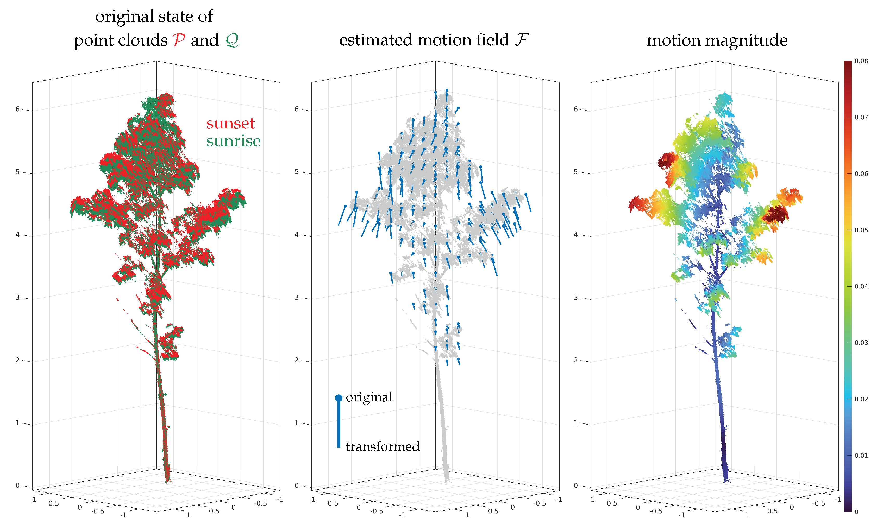
- Wang, D.; Puttonen, E.; Casella, E. PlantMove: A tool for quantifying motion fields of plant movements from point cloud time series. Int. J. Appl. Earth Obs. Geoinf. 2022, 110, 102781. [Google Scholar] [CrossRef]
- Alcantarilla, P.F.; Nuevo, J.; Bartoli, A. Fast Explicit Diffusion for Accelerated Features in Nonlinear Scale Spaces. In Proceedings of the British Machine Vision Conference, Bristol, UK, 9–13 September 2013. [Google Scholar]



| Experimental Results | ||||||||||
|---|---|---|---|---|---|---|---|---|---|---|
| Use Case | Sec. | 2D/3D | Cell Size | Regularization Weights | #corresp. | #it. | ||||
| 1 | ALS 1 | Section 6.1 | 3D | 125.0 m | 2.00 | 2.00 | 2.00 | 2.00 | 20,000 | 3 |
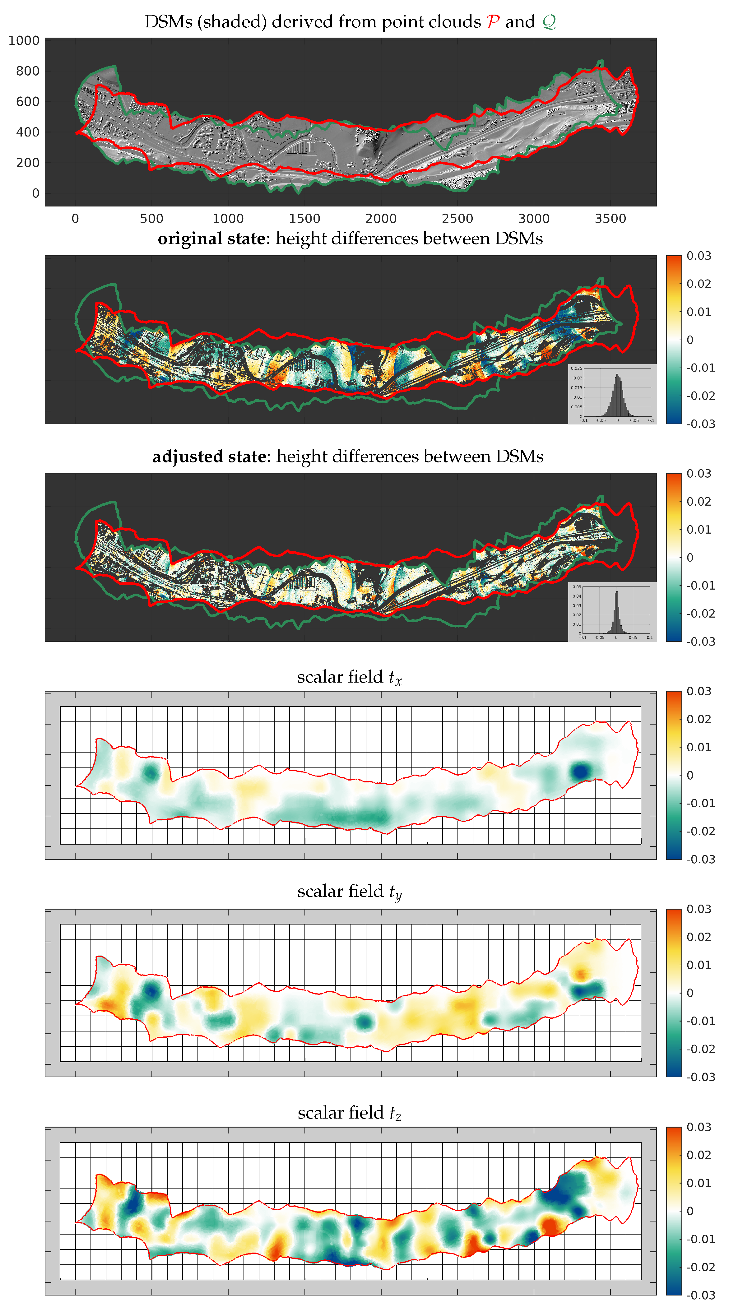
| 2 | ALS 2 | Section 6.2 | 3D | 100.0 m | 1.00 | 1.00 | 1.00 | 0.10 | 20,000 | 3 |
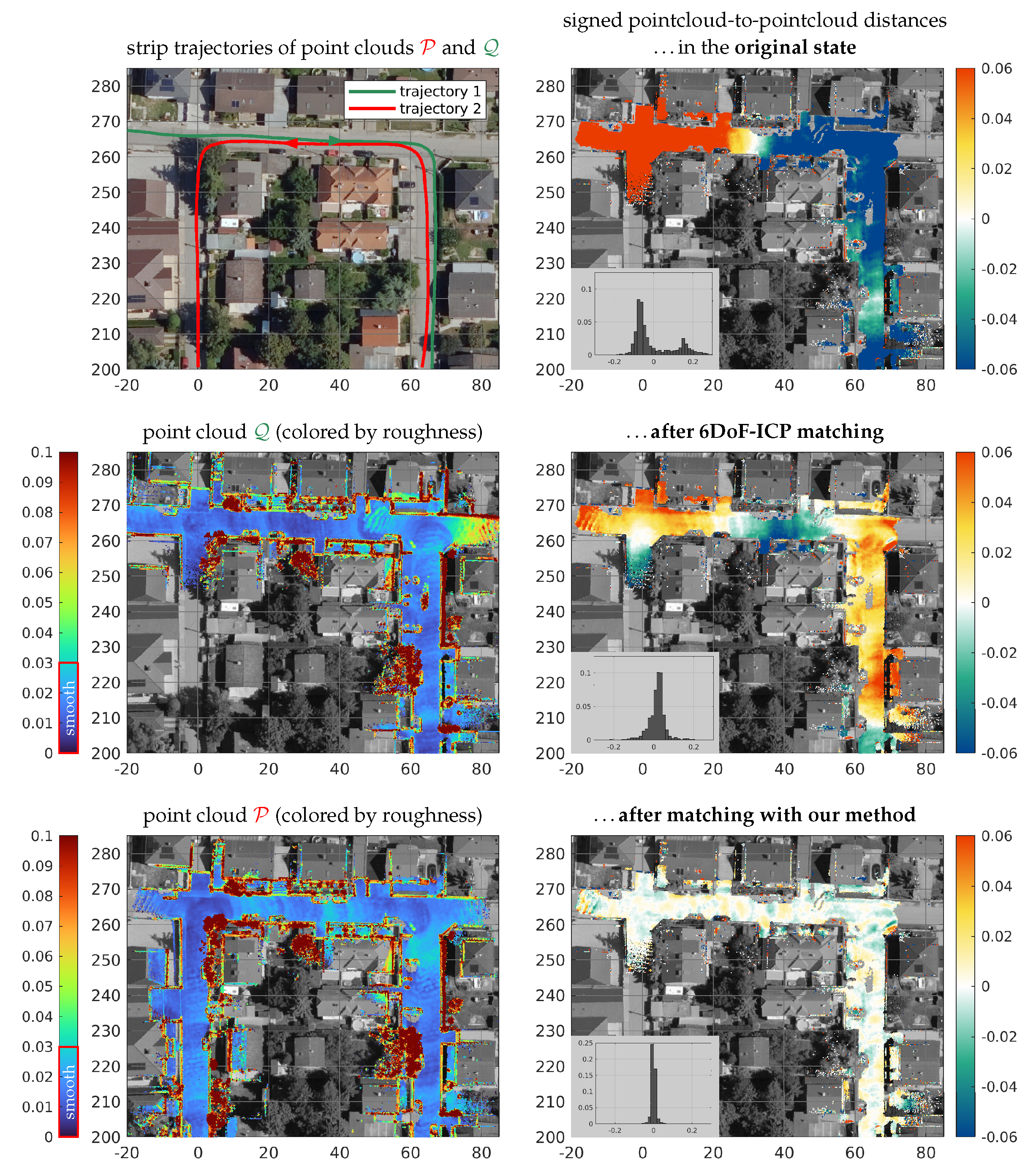
| 3 | MLS | Section 6.3 | 3D | 5.0 m | 0.10 | 0.10 | 0.10 | 0.10 | 10,000 | 3 |
| 4 | TLS | Section 6.4 | 3D | 2.0 m | 0.01 | 0.01 | 0.01 | 0.01 | 10,000 | 5 |
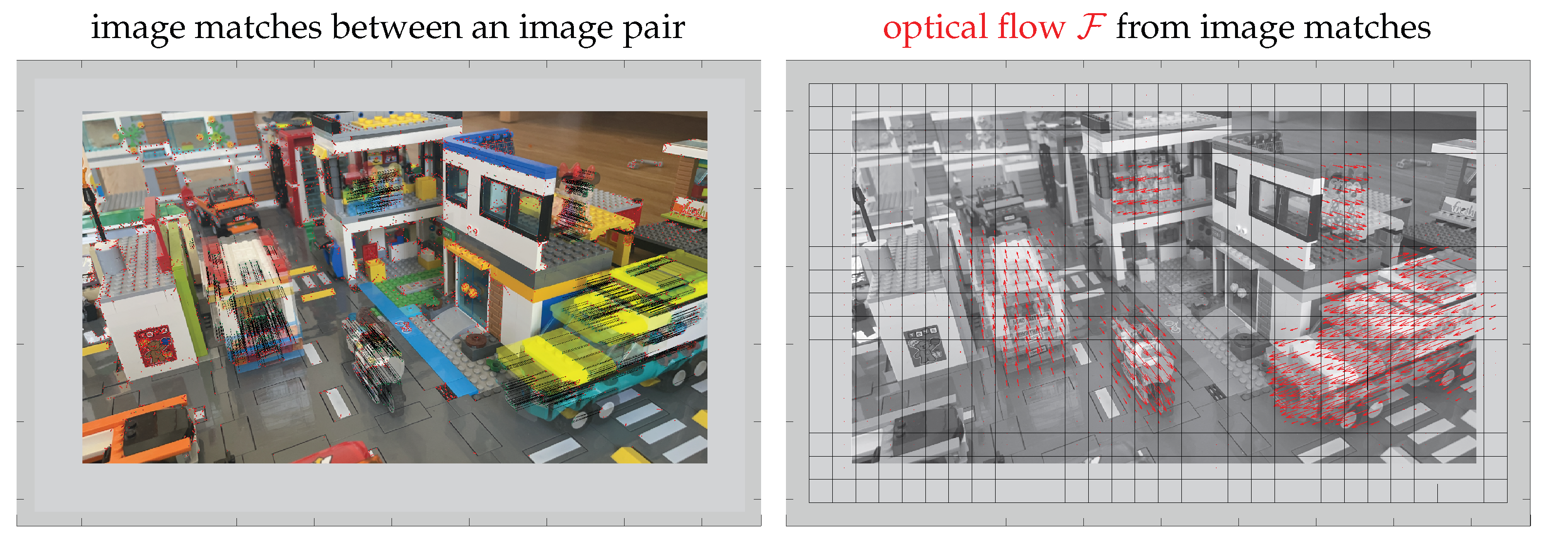
| 5 | Opt. flow | Section 6.5 | 2D | 15.0 px | 0.20 | 0.10 | 0.10 | – | 6713 | 1 |
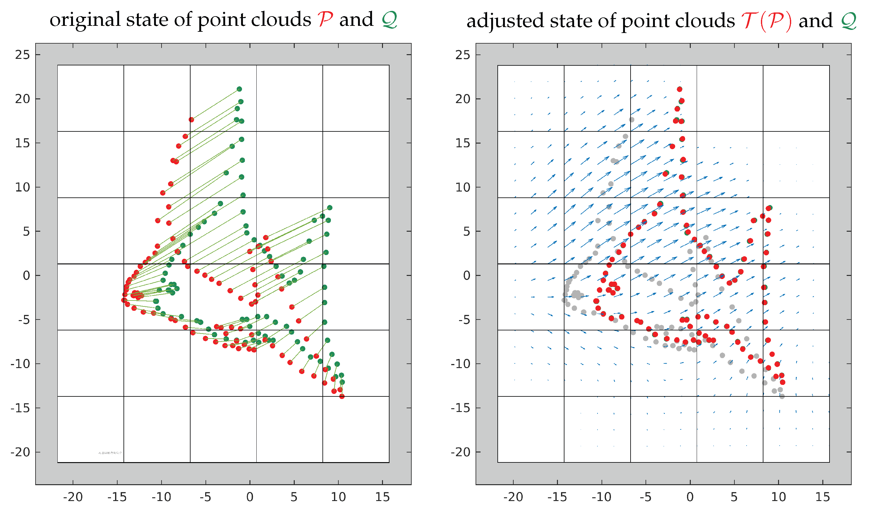
| 6 | Fish | Section 6.6 | 2D | 7.5 | 0.10 | 0.10 | 0.10 | – | 91 | 1 |
| 7 | Hand | Section 6.6 | 2D | 15.0 | 0.05 | 0.05 | 0.10 | – | 36 | 1 |
Disclaimer/Publisher’s Note: The statements, opinions and data contained in all publications are solely those of the individual author(s) and contributor(s) and not of MDPI and/or the editor(s). MDPI and/or the editor(s) disclaim responsibility for any injury to people or property resulting from any ideas, methods, instructions or products referred to in the content. |
© 2023 by the authors. Licensee MDPI, Basel, Switzerland. This article is an open access article distributed under the terms and conditions of the Creative Commons Attribution (CC BY) license (https://creativecommons.org/licenses/by/4.0/).
Share and Cite
Glira, P.; Weidinger, C.; Otepka-Schremmer, J.; Ressl, C.; Pfeifer, N.; Haberler-Weber, M. Nonrigid Point Cloud Registration Using Piecewise Tricubic Polynomials as Transformation Model. Remote Sens. 2023, 15, 5348. https://doi.org/10.3390/rs15225348
Glira P, Weidinger C, Otepka-Schremmer J, Ressl C, Pfeifer N, Haberler-Weber M. Nonrigid Point Cloud Registration Using Piecewise Tricubic Polynomials as Transformation Model. Remote Sensing. 2023; 15(22):5348. https://doi.org/10.3390/rs15225348
Chicago/Turabian StyleGlira, Philipp, Christoph Weidinger, Johannes Otepka-Schremmer, Camillo Ressl, Norbert Pfeifer, and Michaela Haberler-Weber. 2023. "Nonrigid Point Cloud Registration Using Piecewise Tricubic Polynomials as Transformation Model" Remote Sensing 15, no. 22: 5348. https://doi.org/10.3390/rs15225348
APA StyleGlira, P., Weidinger, C., Otepka-Schremmer, J., Ressl, C., Pfeifer, N., & Haberler-Weber, M. (2023). Nonrigid Point Cloud Registration Using Piecewise Tricubic Polynomials as Transformation Model. Remote Sensing, 15(22), 5348. https://doi.org/10.3390/rs15225348


