Abstract
Lidar has emerged as an important technology for the high-precision three-dimensional remote sensing of the ocean. While oceanic lidar has been widely deployed on various platforms, its underwater deployment is relatively limited, despite its significance in deep-sea exploration and obstacle avoidance for underwater platforms. Underwater lidar systems must meet stringent requirements for high performance, miniaturization, and high integration. Single-photon lidar, by elevating the detection sensitivity to the single-photon level, enables high-performance detection under the condition of a low-pulse-energy laser and a small-aperture telescope, making it a stronger candidate for underwater lidar applications. However, this imposes demanding requirements for the data acquisition system utilized in single-photon lidar systems. In this work, a self-developed multi-channel acquisition system (MCAS) with a high-resolution and real-time histogram statistics capability was developed. By utilizing field-programmable gate array (FPGA) technology, a method that combines coarse counters with multi-phase clock interpolation achieved an impressive resolution of 0.5 ns and enabled a time of flight duration of 1.5 μs. To address counting instability, a dual-counter structure was adopted in the coarse counter, and real-time histogram statistics were achieved in the data acquisition system through a state machine. Furthermore, the non-uniform phase shift of the clock was analyzed, and a correction algorithm based on code density statistics was proposed to mitigate the periodic modulation of the backscattered signal, with the effectiveness of the algorithm demonstrated through experimental results. The robustness and stability of the MCAS were validated through an underwater experiment. Ultimately, the development of this compact acquisition system enables the implementation of underwater single-photon lidar systems, which will play a crucial role in underwater target imaging, obstacle avoidance in underwater platforms, and deep-sea marine environment monitoring.
1. Introduction
Oceanic lidar technology has become a crucial supplement to passive ocean color remote sensing and has been applied in various areas [1], including underwater topography [2], measurement of inherent optical properties and apparent optical properties of the ocean [3], assessment of phytoplankton [4], colored dissolved organic matter [5], and bubbles [6]. Additionally, it has been utilized in the study of upper ocean dynamics and other related applications [7]. Furthermore, due to the ability of lidar to penetrate the air–water interface, it possesses flexibility for deployment and has been applied on various platforms such as ships [8], unmanned aerial vehicles (UAVs) [9], aircraft [10], and even satellites [11]. However, the deployment of lidar underwater is extremely limited, despite its importance in underwater scientific exploration, maintenance of underwater equipment, and monitoring of water environments in deep-water regions [12]. This is primarily due to the fact that, in order to enhance the signal-to-noise ratio (SNR), lidar technology employs lasers with high pulse energy and large-aperture telescopes. However, the limited energy supply and constrained space on underwater platforms, such as autonomous underwater vehicles (AUVs), pose challenges for the underwater deployment of lidar systems.
Fortunately, the advent of single-photon detection technology has promoted the underwater deployment of lidar [13,14]. This technology enables lidar systems to achieve long detection ranges and high temporal-spatial resolution using only a low-pulse-energy laser and a small-aperture telescope, thereby realizing a compact, lightweight, and highly integrated design that facilitates deployment on underwater platforms, such as AUVs. Furthermore, the single-photon detection technique has been applied in atmospheric remote sensing [15,16,17], distributed fiber optic sensing [18,19], underwater target imaging [12], and more recently, in marine lidar systems [20,21,22,23]. Compared to single-photon atmospheric lidar systems, which can detect distances of several km or even tens of km with spatial resolutions in the m range, underwater lidar systems have a maximum measurement range of about a hundred meters and require spatial resolutions in the cm range. As a result, the acquisition of electrical signals from single-photon detectors has introduced new demands on digital acquisition cards. Therefore, this work aims to develop a high-precision, multi-channel data acquisition system (MCAS) specifically tailored to meet the requirements of single-photon underwater lidar.
Until now, a variety of acquisition systems based on digital schemes have been developed for single-photon lidar, including commercially available options such as EASY-MCS [24], Pico-Quant’s Hydraharp series [25], Swabian Instrument’s Time Tagger Ultra [26], and IdQuantique’s ID900 Series [27]. However, to meet the specific criteria for an acquisition system in underwater single-photon lidar applications, an optimized design scheme is required. These requirements include a GHz/s sampling rate (providing distance resolution in the order of tens of cm), μs sampling duration (enabling unambiguous detection beyond 100 m), a minimum of three channels, real-time histogram statistics functionality, and consideration of power consumption and size constraints for underwater applications.
Various schemes have been explored. One approach is the multi-phase clock separation method, which utilizes the clock manager within the FPGA to generate multiple clock combinations with phased delays, allowing for the monolithic integration of hundreds of channels [28]. However, this method typically has a time resolution lower than 500 ps due to the limited number of clocks. Another technique is the Vernier delay line (VDL) technique, which can achieve a maximum time resolution of 30 ps [29]. The stability of the delay units in the two measurement delay lines is crucial for this technique, but designing a stable delay line can be challenging. A delay chain interpolation method involves sending a start signal to multiple delay units with the same delay, allowing them to propagate sequentially. When the stop signal arrives, the number of propagated delay units is counted to achieve fine time measurement. This method is widely used when a resolution higher than 100 ps is required [30,31,32]. There are also FPGA-based delay chain methods that achieve high resolution, but with limited sampling duration. For example, one method based on an FPGA delay chain achieves a resolution of 1.7 ps, but has a sampling duration of only 6.25 ns. Another FPGA-based delay chain achieves a measurement resolution of 10 ps, but has a sampling duration of only 20 ns [33].
After exploring the above-mentioned options, this work proposes and demonstrates a novel scheme based on a novel coarse counting and multi-phase clock interpolation technology. A multi-phase clock interpolation technique is applied, which improves the sampling precision from 5 ns achieved solely via coarse counting, to 0.5 ns. The designed solution successfully implements a three-channel acquisition system with a high sampling rate of 2 GHz and a data acquisition duration of 1.5 μs.
Furthermore, when a digital data acquisition system is used to collect lidar backscattered signals, due to the integral nonlinearity of the data acquisition card, i.e., the small difference in bin widths, the lidar backscattered signals appear periodically modulated. Many correction algorithms have been proposed to correct the lidar backscattered signals, including code density [34], direct correction [35], multiple measurements [36], and sliding window [37]. Through discrete Fourier transform (DFT) analysis, this work studied the mechanism of the periodic modulation of backscattered signals caused by the integral nonlinearity of data acquisition, and proposed a corresponding correction algorithm. Finally, the feasibility and stability of the data acquisition system were verified through the operation of the single-photon underwater lidar.
2. Principle and Implementation of the MCAS
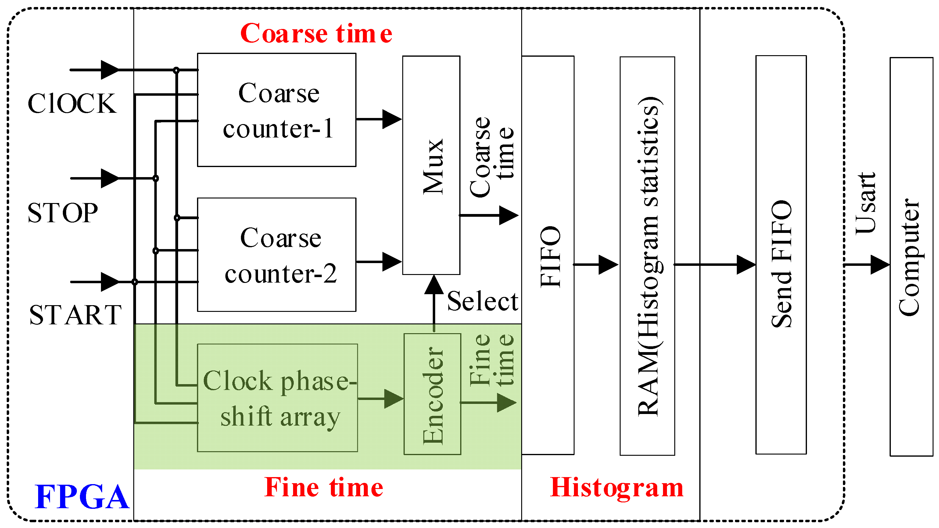
Figure 1 illustrates the block diagram of the MCAS, which is composed of three subsystems: coarse time, fine time, and histogram.
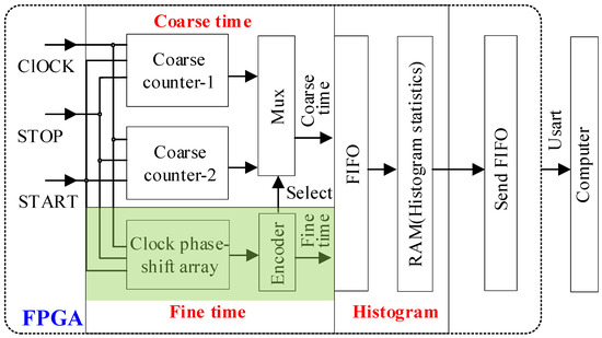
Figure 1.
Block diagram of the MCAS. RAM: random access memory; FIFO: first in first out.
The working procedure is as follows:
- Step 1:
- After powering on and initializing the MCAS, Coarse counter-1 and Coarse counter-2 count independently according to the rising and falling edges of the 200 MHz clock signal, respectively.
- Step 2:
- Upon receiving the synchronization signal (START), which represents the initiation time of the laser pulse emission, the fine time value of the fine time module and the coarse time value of the coarse time module are obtained and combined to form the time tags of START.
- Step 3:
- The same process is carried out for the stop signal (STOP), which indicates the recorded time of the detected event, specifically the arrival time of the lidar backscattered photon, to obtain the time tags of STOP.
- Step 4:
- The time tags of the STOP signal are subtracted from the time tags of the START signal, and the result is stored in a first in first out (FIFO) memory.
- Step 5:
- Steps 3 and 4 are repeated for each STOP signal until the START signal appears again, and then Step 2 is performed to update the time tags value of the original START signal.
- Step 6:
- Histogram statistics on the time tags in the FIFO memory is performed synchronously. The start time of each emitted laser pulse is recorded as the start tags, the stop time when a backscattered photon is detected is recorded as the stop tags, the time difference between each stop tag and its corresponding start tag is calculated as the photon time-of-flight, and a histogram of all photon time-of-flights is generated [38]. Statistical results will be sent to the Send FIFO memory, and then perform the next histogram statistics.
- Step 7:
- The data in Send FIFO memory of the MCAS are then sent to a computer or storage device via the serial port.
2.1. Timing Principles of the Time-to-Digital Converter
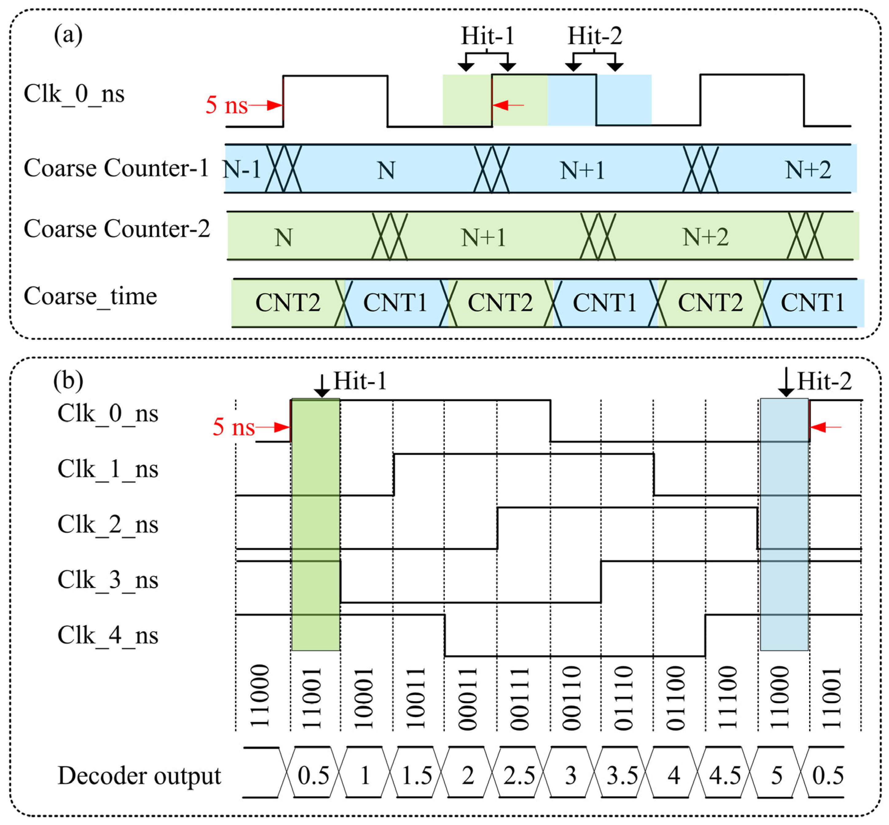
To simultaneously achieve a long measurement range and high time resolution, the MCAS utilizes a time-to-digital converter (TDC) that combines coarse time and fine time techniques. Coarse time utilizes a double counter structure, as depicted in Figure 2a, to effectively avoid the metastability of the counter when it changes. Clk_0_ns is used as the clock of the coarse counter. Coarse counter-1 counts on the rising edge of the clock, while Coarse counter-2 counts on the falling edge. When the Hit signal appears, the value of Coarse counter-2 or Coarse counter-1 is selected as the coarse time tag value of the Hit signal, depending on whether the Hit signal appears in the first half period or the latter half period of the coarse counter clock, thus ensuring that the coarse time tag value is stable. For instance, when the Hit signal appears at Hit-1 (light green part) as shown in Figure 2a, the value of Coarse counter-2 is stable, while the value of Coarse counter-1 is unstable near the rising edge of the counter clock. Therefore, the value of Coarse counter-2 is selected as the coarse time value of Hit-1. When the Hit signal appears at Hit-2 (light blue part), the value of Coarse counter-1 is stable, while the value of Coarse counter-2 is unstable near the falling edge of the counter clock. Consequently, the value of Coarse counter-1 is selected as the coarse time value of Hit-2. By employing the double coarse counter structure, the metastable problem caused by the synchronous acquisition of the coarse counter value at the counting moment of the coarse counter is avoided, thereby ensuring that the coarse counter value at any moment is reliable.
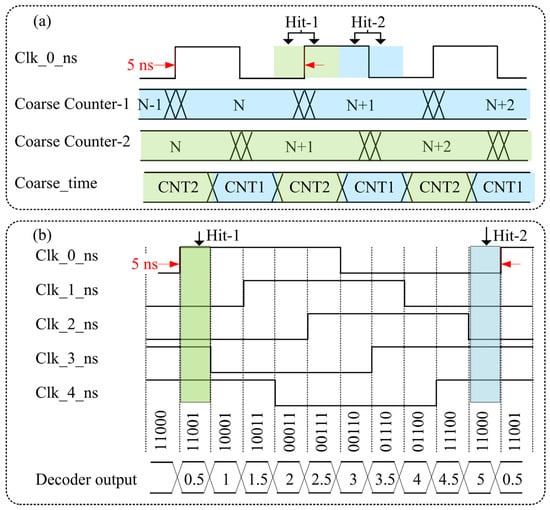
Figure 2.
Schematics of coarse time (a) and fine time (b) in TDC. Both utilize the synchronous clock Clk_0_ns with a frequency of 200 MHz, where the 5 ns period is indicated by the red arrow.
Fine time utilizes the multi-phase clock sampling technique, which is an interpolation technique based on phase-shift clock signals that are implemented through the FPGA. It is worth noting that to ensure synchronization, both the coarse clock and the fine clock are derived from the same base clock. This method is based on employing the phase-locked loop (PLL) incorporated in the FPGA to generate a clock signal with a precise frequency and phase shift. Using the signal to be measured, clock signals are sampled in multiple phases. By combining the levels of the multi-phase clock, the fine timing of the signal can be derived. As illustrated in Figure 2b, the PLL incorporated in the FPGA is used to generate five clock signals (Clk_0_ns, Clk_1_ns, Clk_2_ns, Clk_3_ns, and Clk_4_ns) with a frequency of 200 MHz (±20 ppm) and different phases, each 1 ns out of phase with the previous clock. When the event Hit-1 appears in the light green section, the level combination [Clk_4_ns Clk_3_ns Clk_2_ns Clk_1_ns Clk_0_ns] of the five clocks sampled at this time is 11001, and the corresponding time tag is 0.5 ns. Similarly, when the event Hit-2 appears in the light blue section, the level combination of the five clocks sampled at this time is 11000, and the corresponding time tag is 5 ns. Therefore, with a clock period of 5 ns, the MCAS achieves a time resolution by dividing the 5 ns clock period into 10 equidistant parts, each interval corresponding to 0.5 ns. The measurement resolution can be enhanced by increasing the number of phase shifts within a single period. However, the number of multi-phase clocks that can be employed is restricted by the process level of the FPGA. This method is relatively straightforward to implement for time interval measurements that require a precision of 0.5 ns.
2.2. Principle of the Histogram Statistics
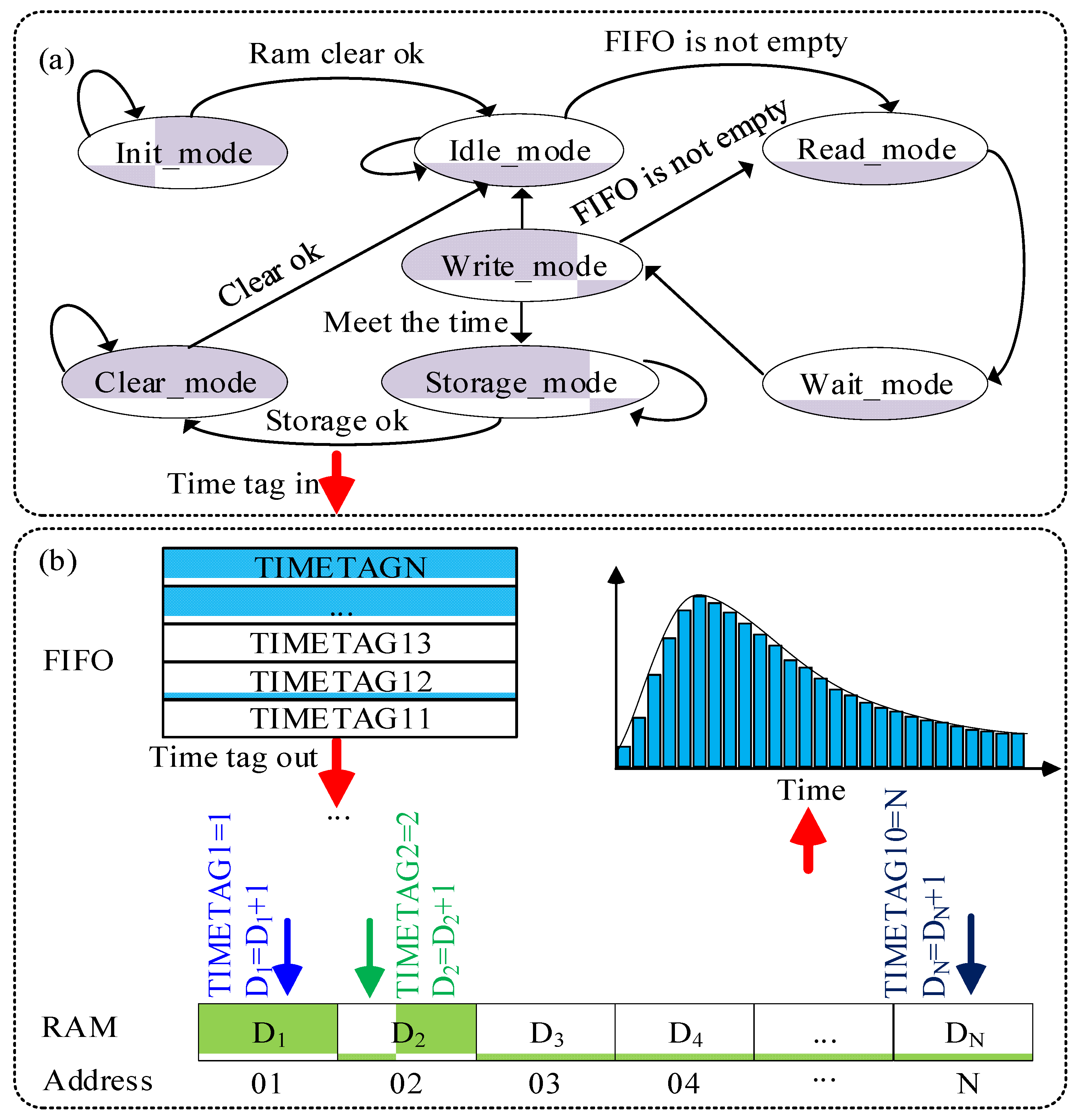
MCAS executes the function of generating real-time histogram statistics for the time tags produced by the TDC module. It then forwards the statistical results to the Send FIFO memory. The statistical principle of the single-photon distribution histogram employs a design method based on the FPGA state machine. The state machine, depicted in Figure 3, comprises seven modes, namely, Init_mode, Idle_mode, Read_mode, Wait_mode, Write_mode, Storage_mode, and Clear_mode, along with their corresponding mode transition conditions. Init_mode initializes the system and assigns statistical parameters for proper configuration. Idle_mode waits for gaps or intervals between time tags to ensure synchronization and timing. Read_mode accesses the histogram statistics RAM using received time tags to retrieve stored statistical data. Wait_mode ensures that the correct data are obtained by waiting for values to be read into registers from the corresponding addresses in the histogram statistics RAM. Write_mode updates or writes new histogram statistics data at the appropriate addresses. Storage_mode transfers completed histogram statistics within the designated time frame to the Send FIFO memory for storage and retrieval. Clear_mode resets the statistical data by clearing the results from the previous frame in the histogram statistics RAM, preparing for the next cycle of data collection.
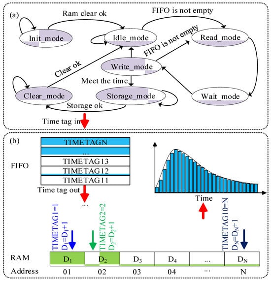
Figure 3.
State machine diagram of the histogram (a) and histogram diagram (b).
As shown in Figure 3b, the length ‘N’ of the random-access memory (RAM) cell relies on the number of bins of the histogram that needs to be statistically analyzed. For instance, if we need to analyze the distribution of all STOP signals within 500 ns from the START signal, and given that the resolution of MCAS is 0.5 ns, we would require a RAM cell with a length of 1000 points. The specific workflow is as follows:
- Step 1:
- Upon power-up and initialization, the MCAS requests a RAM cell of length ‘N’, which depends on the number of bins of the histogram that need statistical analysis.
- Step 2:
- Once the RAM cell is cleared, the MCAS transitions from Init_mode to Idle_mode.
- Step 3:
- In cases where the FIFO RAM still has stored time tags, the MCAS reads these tags and uses them as addresses to locate corresponding RAM cells. The MCAS then reads the value stored within these cells, increases the value by one, and then stores it back to the original location. However, if the FIFO RAM is empty, the MCAS remains in Idle_mode.
- Step 4:
- If the statistical time has not yet reached the set value, and the FIFO RAM is not empty, the MCAS continues executing Step 2. Once the statistical time reaches the set value, the MCAS transfers the statistical results to Send FIFO RAM for the corresponding RAM cell. After the transfer is completed, the RAM cell is cleared, and MCAS returns to Idle_mode to commence the next cycle of histogram statistics. Ultimately, the number of time tags (i.e., photon counts) at different distances are recorded. This allows for the creation of the histogram depicting the photon count distribution at various distances, as collated from multiple laser pulses, as depicted in Figure 3b.
2.3. Performance Verification
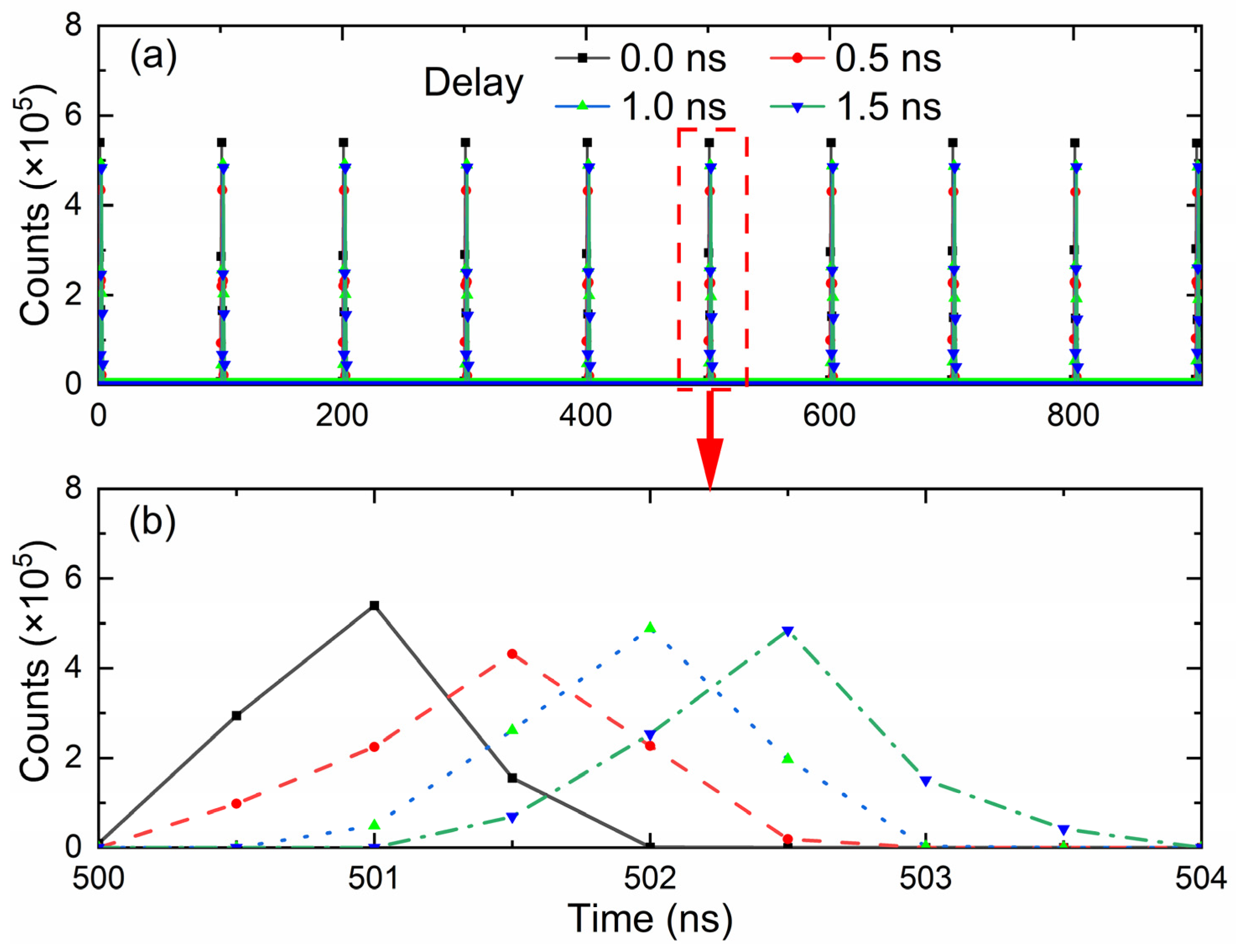
The key parameters of MCAS are shown in Table 1. To test the resolution of MCAS, an arbitrary function generator AFG31000 (Tektronix Inc., Beaverton, OR, USA) with a root mean square (RMS) jitter of 2.5 ps, timing resolution of 10 ps, peak-to-peak voltage of ±5 V, and a rise/fall time of less than or equal to 3.5 ns was employed to generate START signals at 1 MHz and STOP signals at 10 MHz. Then, these two signals were connected to the corresponding channels of MCAS for 1 s histogram statistics. Adjusted delay times of the STOP signal with the increments of 0.5 ns were used to generate the histogram statistics, as shown in Figure 4. Figure 4b is a local zoom-in of Figure 4a from 500 ns to 504 ns. The statistical results derived from the distribution histogram demonstrate that the corresponding STOP signals undergo corresponding delays in steps of 0.5 ns, indicating that the MCAS achieves a time resolution of 0.5 ns. Furthermore, the histograms exhibit a triangular shape with a certain width, characterized by a full width at half maximum (FWHM) of approximately 1 ns. This broadening effect is primarily caused by the limited precision resolution of the arbitrary function generator and MCAS.

Table 1.
Key parameters of the MCAS.
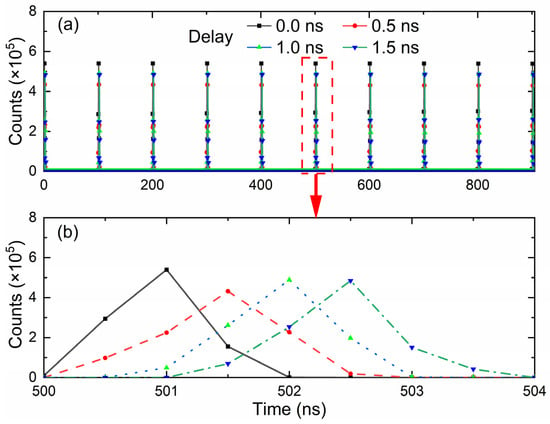
Figure 4.
(a) Verification of the time resolution of the MCAS, and (b) local zoom-in of (a).
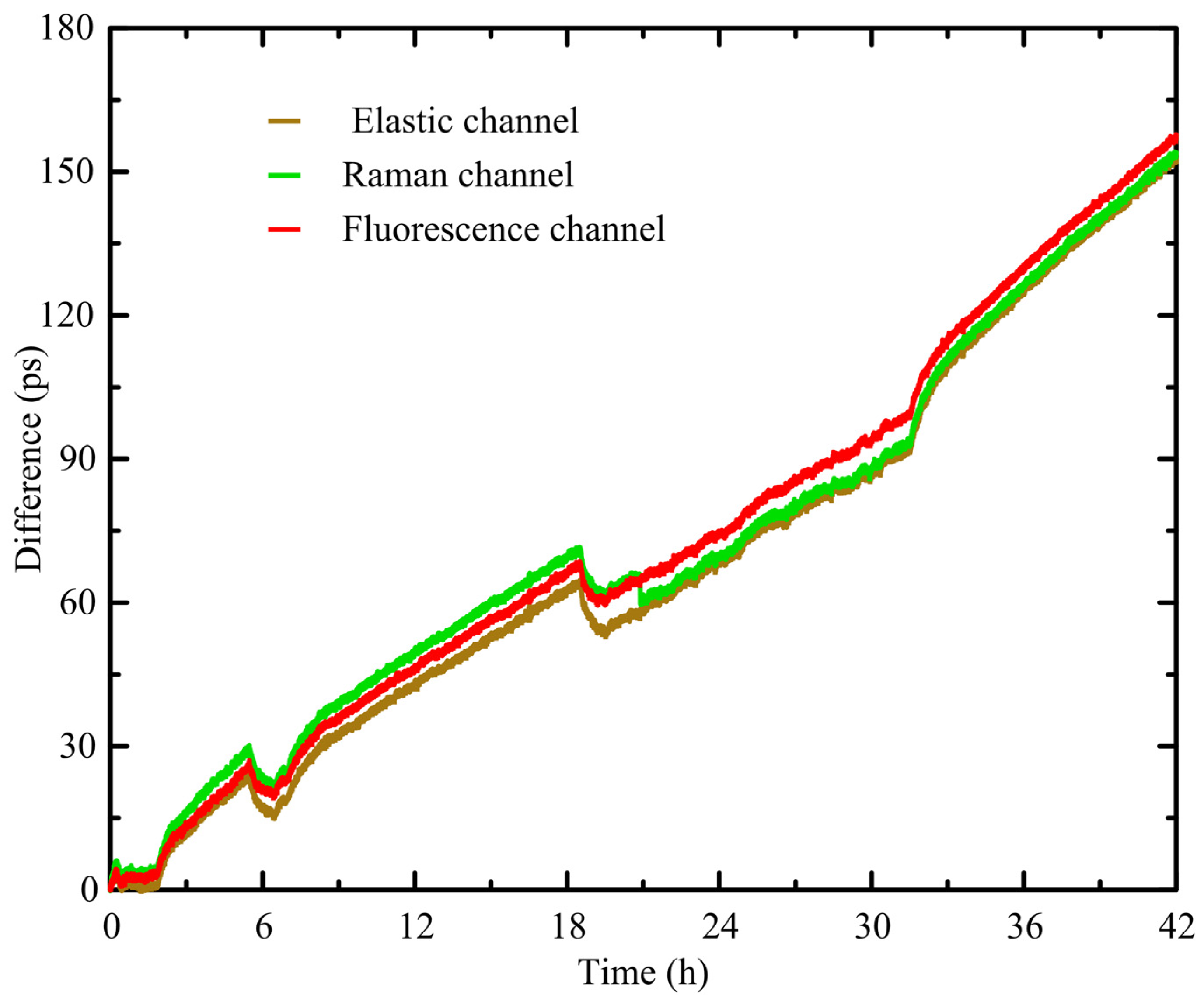
To verify the consistency and voltage stability of the three channels in the MCAS prototype, a signal generator (AFG31000 series) was employed. The generator was used to generate START signals at 1 MHz, while STOP signals at 10 MHz were utilized as input signals for the three channels of the MCAS. The histogram accumulation time was set to 1 s, and the average value of the temporal distance between the first STOP pulse and the corresponding START signal was calculated for each channel as the measurement result. The measurements for the three channels were performed independently. After 42 h of continuous measurement, the results depicted in Figure 5 revealed a consistent shift of ~4 ps per hour across all three channels. These measurement results indicate that the three channels of the MCAS demonstrate excellent consistency and voltage stability.
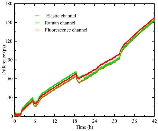
Figure 5.
Verification of MCAS good consistency and voltage stability.
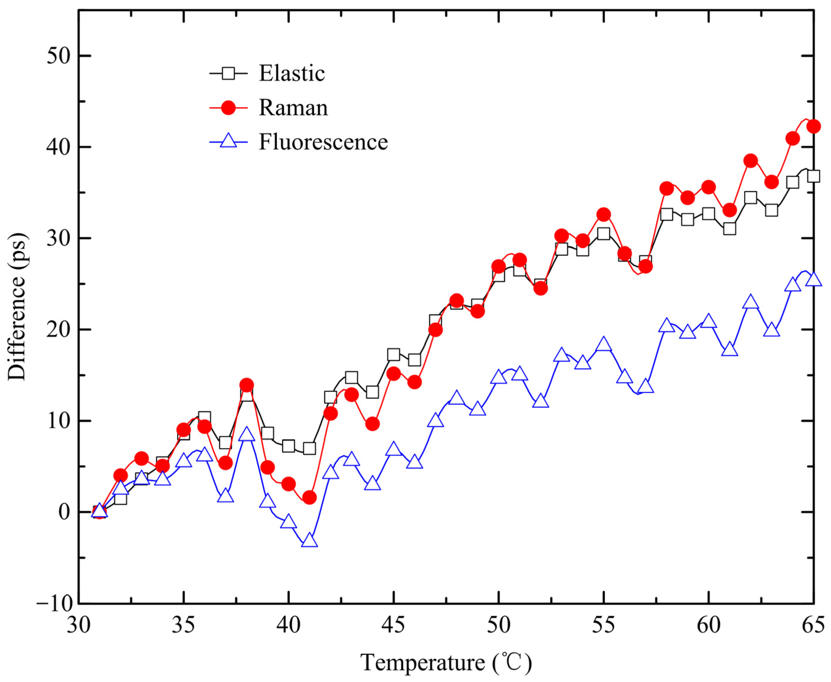
To verify the temperature stability of the MCAS, the operating temperature of the MCAS was increased from 30 °C to 60 °C during the aforementioned experimental process. The statistical shift results depicted in Figure 6 demonstrate a consistent shift of ~1.1 ps per °C across all three channels, indicating that the three channels of the MCAS exhibit excellent temperature stability. It is worth noting that the discontinuities observed at 6, 18, and 33 h in Figure 5 are the result of temperature variations in the surroundings. To investigate this, a temperature stability experiment was conducted, with the results depicted in Figure 6 validating this hypothesis. The drift of the difference with temperature shown in Figure 6 is due to the influence of temperature on the stability of the crystal oscillator, which in turn affects the operational clock of the MCAS system. To address this issue, temperature control was implemented for the underwater lidar system. The temperature drift was controlled within a range of ±1 °C.
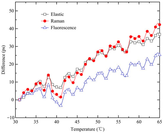
Figure 6.
Verification of MCAS temperature stability.
3. Application of MCAS in the Single-Photon Underwater Lidar
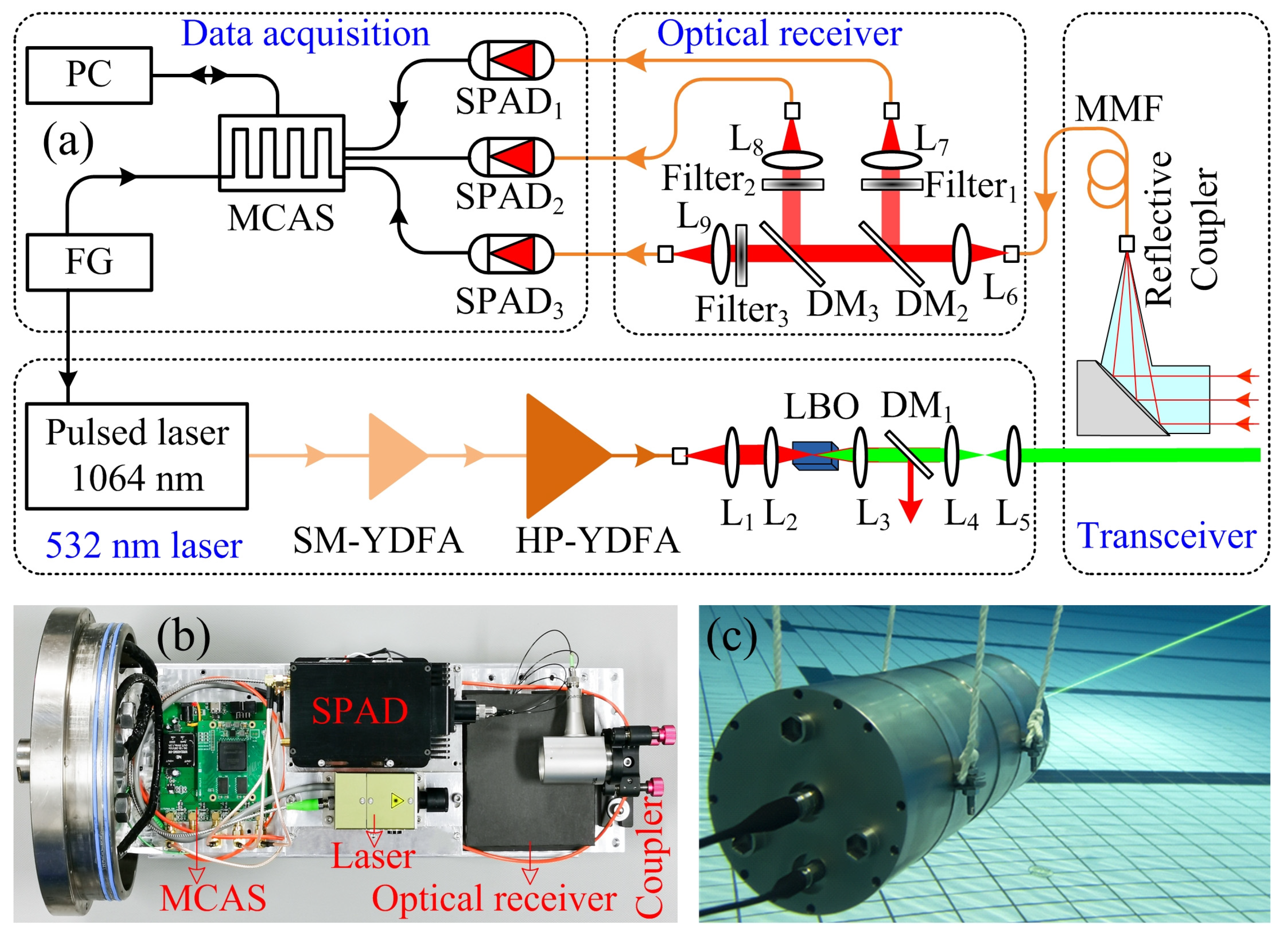
The MCAS prototype is utilized in a single-photon underwater lidar system, as illustrated in Figure 7. This system is specifically designed for the measurement of the optical parameters of water. The single-photon underwater lidar is composed of a green pulse laser, an optical receiver section, several single-photon avalanche diodes (SPADs), a MCAS, and an auxiliary control section (controller). The 532 nm laser emits a pulse with a pulse duration of 3 ns and a repetition rate of 340 KHz. The distance resolution of a lidar system is determined by the laser pulse width, the response speed of the detector, and the sampling rate of the MCAS. The narrow pulse width, combined with a high-sampling-rate MCAS, contributes to the measurement of lidar backscattered signals with higher spatial resolution. The laser system employs a master oscillator power amplifier (MOPA) structure, which incorporates a single-mode pulsed seed laser operating at 1064 nm. The seed laser undergoes two stages of amplification, first through a single-mode ytterbium-doped fiber amplifier (SM-YDFA) and then through a high-power ytterbium-doped fiber amplifier (HP-YDFA). The amplified laser output then passes through a lithium borate crystal (LBO), which converts the 1064 nm fundamental frequency light to 532 nm green light using second harmonic generation. Finally, up to 1.0 W of average power is achieved with the beam divergence of 0.5 mrad.
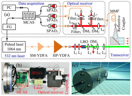
Figure 7.
(a) Schematic diagram of the single-photon underwater lidar. SM-YDFA: single-mode ytterbium-doped fiber amplifier; HP-YDFA: high-power ytterbium-doped fiber amplifier; LBO: lithium borate; DM: dichroic mirror; MMF: multimode fiber; SPAD: single-photon avalanche diode; MCAS: multi-channel acquisition system; FG: function generation; PC: personal computer; L1–9: lens. (b) Internal photo of the single-photon underwater lidar. (c) Photo of the single-photon lidar in operation underwater.
To achieve a miniaturized and robust structure for the single-photon underwater lidar, a fiber-connected configuration was adopted. To avoid saturation of the single-photon detector caused by strong signals in the near field, the single-photon underwater lidar employs a separate transmit-receive configuration. Due to the influence of the geometric overlap factor, the near-field signals of the lidar are attenuated, enabling the measurement of a wide dynamic range. The backscattered signal from the water is coupled in a 105-um multimode fiber (MMF) by a collimator with a 27.5 mm focal length, which corresponds to the field of view (FOV) of ~3.8 mrad. This narrow receiving FOV in our lidar system offered a significant backscattering noise suppression. The distance between the transmitted laser and received collimator is ~15 mm. The optical receiver segment receives the backscattered signal and isolates it into elastic, Raman from water, and fluorescence elements through a combination of filters and dichroic mirrors. The elastic, Raman, and fluorescence channels have center wavelengths of 532 nm, 650 nm, and 685 nm, respectively. Due to the narrow spectrum of the elastic backscattered signal, a 0.1 nm bandwidth filter was chosen for the elastic channel to better suppress background noise. However, both the Raman spectra of water and the fluorescence spectra of phytoplankton, when excited by a laser, exhibit broad signal characteristics [39,40]. To minimize interference from other substances excited by the laser and effectively suppress background noise, a Raman filter with a bandwidth of 6 nm and a fluorescence filter with a bandwidth of 10 nm were selected. The profile data from these three channels are utilized to invert the inherent optical properties (IOPs) of the water, the water depth, and the concentration profile of Chlorophyll a [13,14,23]. Compared to other oceanic lidar systems, the single-photon underwater lidar enables the detection of optical property profiles in water bodies using small-aperture and narrow-FOV optical telescopes. This allows the lidar attenuation coefficient (Klidar) to approach the beam attenuation coefficient (c) as an IOP, rather than the diffuse attenuation coefficient (Kd) as an apparent optical property (AOP) [41]. Additional, by employing single-photon detection technology, weak Raman profiles and laser-induced fluorescence profiles in water bodies can be detected. On one hand, this enables the identification of substances in the water, such as oil spills [13]. On the other hand, it allows for more accurate inversion of optical parameters in the water [23]. The associated data processing and inversion algorithms will be discussed in subsequent articles.
Each of these components is then detected by a corresponding SPAD (SPCM-AQRH-16, Excelitas Technologies Corp., Waltham, MA, USA,). The timing jitter of the SPAD is approximately 0.5 ns. The output of the SPAD is then connected to the MCAS. It is worth noting that after the single-photon detector detects a single photon, it outputs a single electrical pulse signal. The MCAS then discriminates this pulse, counting it as 1 when the voltage of the pulse exceeds the set discrimination threshold, and as 0 otherwise. The pulse count from the single-photon detector, which corresponds to the number of detected photons, is equal to the count obtained by the MCAS. The dark count rate of the single-photon detector is ~100 counts per second (cps). After histogram statistics, the MCAS sends the collected photon signals via the serial port to a computer for display. The photo of the single-photon underwater lidar is shown in Figure 7a. The lidar chamber, made of high-pressure resistant titanium alloy, enables the lidar to operate underwater. The optical window of the lidar is made of sapphire lens, which can maintain >96% transmission under high pressure. During the assembly, the entire set of lidar components, including the laser, collimator, MCAS, etc., was first mounted onto an aluminum plate. Subsequently, the entire aluminum plate assembly was installed into the lidar chamber. The pressure inside the chamber was ~1 atm. The cylindrical lidar has a diameter of 20 cm and a length of 40 cm. The average power consumption of the lidar is ~80 W, and it weighs 15 kg. The key parameters of the lidar are presented in Table 2.

Table 2.
Key parameters of the single-photon underwater lidar.
To accurately capture signals for evaluating the overall performance of the MCAS, a high-resolution multi-channel TDC (time-to-digital converter) from Swabian Instruments (Stuttgard, Germany) is utilized. The electrical signals from the detector are split using a 1 × 2 splitter, with one path connected to the MCAS and the other path connected to the TDC. The TDC offers a resolution of 1 ps, 9 ps RMS jitter, and 22 ps half-peak width jitter. This configuration enables the simultaneous acquisition of the lidar backscattered signals.
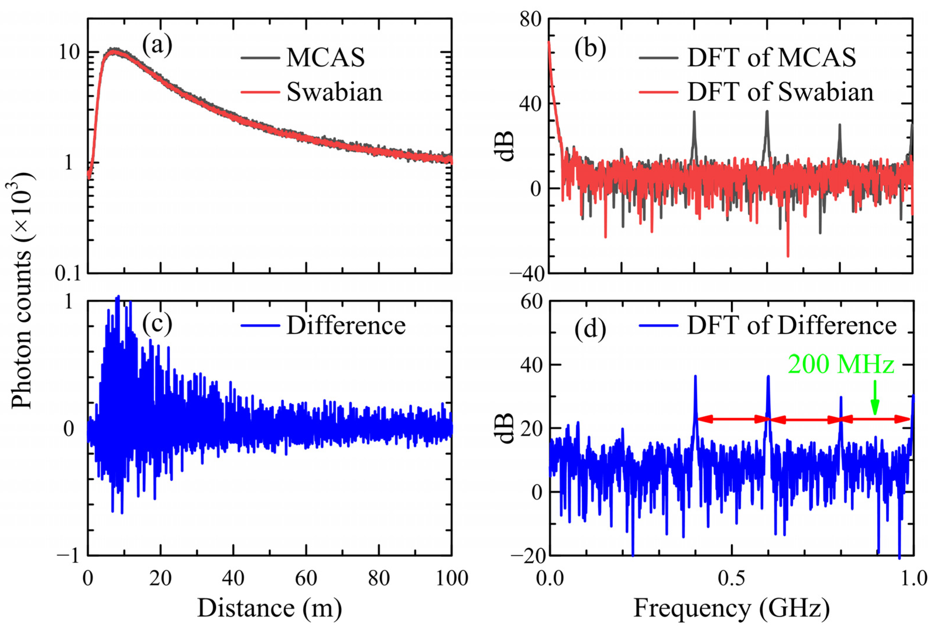
For operational convenience, the underwater lidar was initially used to sense the atmospheric aerosol signal. Figure 8a demonstrates the atmospheric signal obtained from the elastic channel, captured simultaneously using both MCAS and Swabian Instruments. It should be noted that when using this lidar system for atmospheric sensing, the fluorescence and Raman signals from the atmosphere are very weak. Therefore, only the results from the elastic channel are provided. Figure 8b,d illustrate the results of applying the DFT to Figure 8a,c, respectively. The results demonstrate a strong correspondence between the data acquired by MCAS and Swabian Instruments. However, during the frequency domain analysis, the acquisition results of the MCAS reveal the presence of four prominent harmonic signals alongside the fundamental signal, exhibiting a frequency difference of 200 MHz between the harmonics.
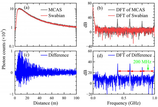
Figure 8.
(a) Elastic channel acquisition results from the MCAS (black line) and TDC from Swabian (red line), (b) DFT of the acquisition results, (c) difference between MCAS and Swabian results, and (d) DTF of difference.
Through analysis, it was found that the harmonic signals observed were generated by the phase-shift clock of the FPGA. The intended phase difference between each clock was set to 1 ns. However, due to limitations in the PLL of FPGA, which involves the number of divisions and multipliers, it was not possible to generate a clock signal with an exact phase difference of 1 ns. In this particular study, the MCAS system employed the FPGA chip EP4CE75F23C8, resulting in an actual phase-shift clock with a phase difference of 1.04 ns. As a consequence, the width of each bin in the TDC was not precisely 0.5 ns, leading to the presence of the harmonic components depicted in Figure 8d. It should be noted that the harmonics are artifacts generated by the system and are not part of the real signal. Consequently, an algorithm has been proposed to correct these harmonics.
4. Correction of Backscattered Signal
As analyzed above, the width of each bin in the TDC cannot be perfectly consistent due to various factors, including the PLL limitations and the influence of layout, power, voltage, temperature, and other parameters in FPGA. Fortunately, the spectrum in Figure 8d shows that the difference fluctuates periodically, with a period of 5 ns (corresponding to 10 Bins). Therefore, a method is proposed to obtain correction coefficients for 10 consecutive bins using the code density method to correct the raw data. The code density method uses a large number of uniformly distributed random pulses as input for the STOP signal. By counting the number of random pulses that fall into each bin, the code density is determined. A wider bin width results in a higher count of random pulses assigned to that bin. Specifically, the arbitrary function generator (AFG31000 series) is utilized to generate a 1.003 MHz START signal and a 30 MHz STOP signal. These signals are then connected to the respective START and STOP channels of the MCAS. Since the frequencies of these two signals are not integer multiples of each other, the rising edge of the STOP signal is randomly positioned relative to the START signal. This ensures that the input random pulses uniformly fall within the range of 0.1 to 1.003 μs.
By counting the number of STOP pulses (the subscript k represents the k-th bin) obtained from each bin of the first 10 bins after a cumulative time of 100 s, the correction coefficient of the k-th bin can be obtained from Equation (1), and the correction coefficient of all bins of the MCAS can be obtained from their periodic relationship according to Equation (2).
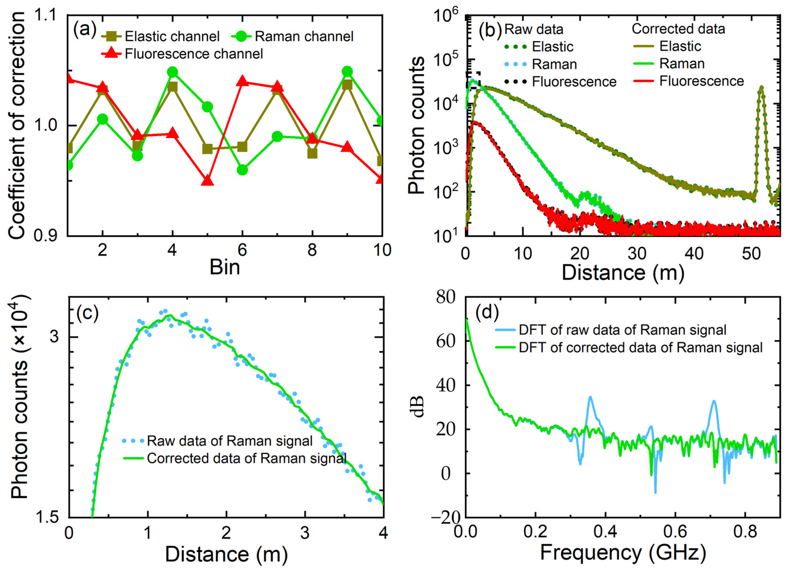
As shown in Figure 9a, the correction coefficients of the first 10 bin widths are obtained by the code density method for all the elastic, Raman, and fluorescence channels. By dividing each data point collected by the MCAS system by its corresponding correction coefficient, the corrected MCAS data can be obtained. The comparison between the pre-corrected and post-corrected lidar backscattered signals is illustrated for all the elastic, Raman, and fluorescence channels in Figure 9b. To enhance the clarity of the corrected results, a segment of the backscattered signal from the Raman channel is presented in Figure 9c,d. The figures clearly demonstrate that the corrected data show a much smoother profile, with a noticeable reduction in the presence of harmonics. This indicates a substantial improvement in the correction process.
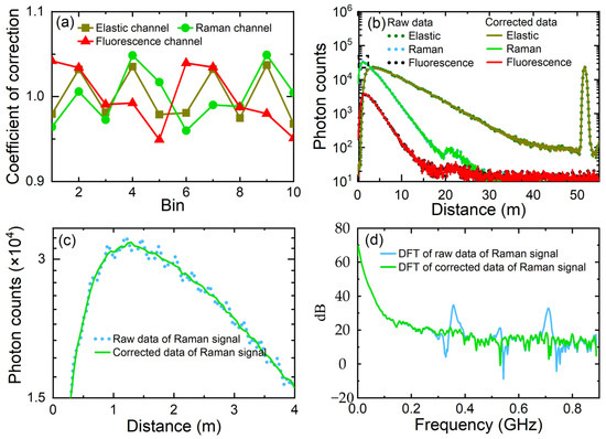
Figure 9.
(a) The 10-bin correction factor of the MCAS in different channels, (b) comparison of the acquisition data from the MCAS before and after correction, (c) local zoom-in of Raman signal from (b), and (d) DFT of the raw Raman signal and the corrected Raman signal.
5. Validation Experiment
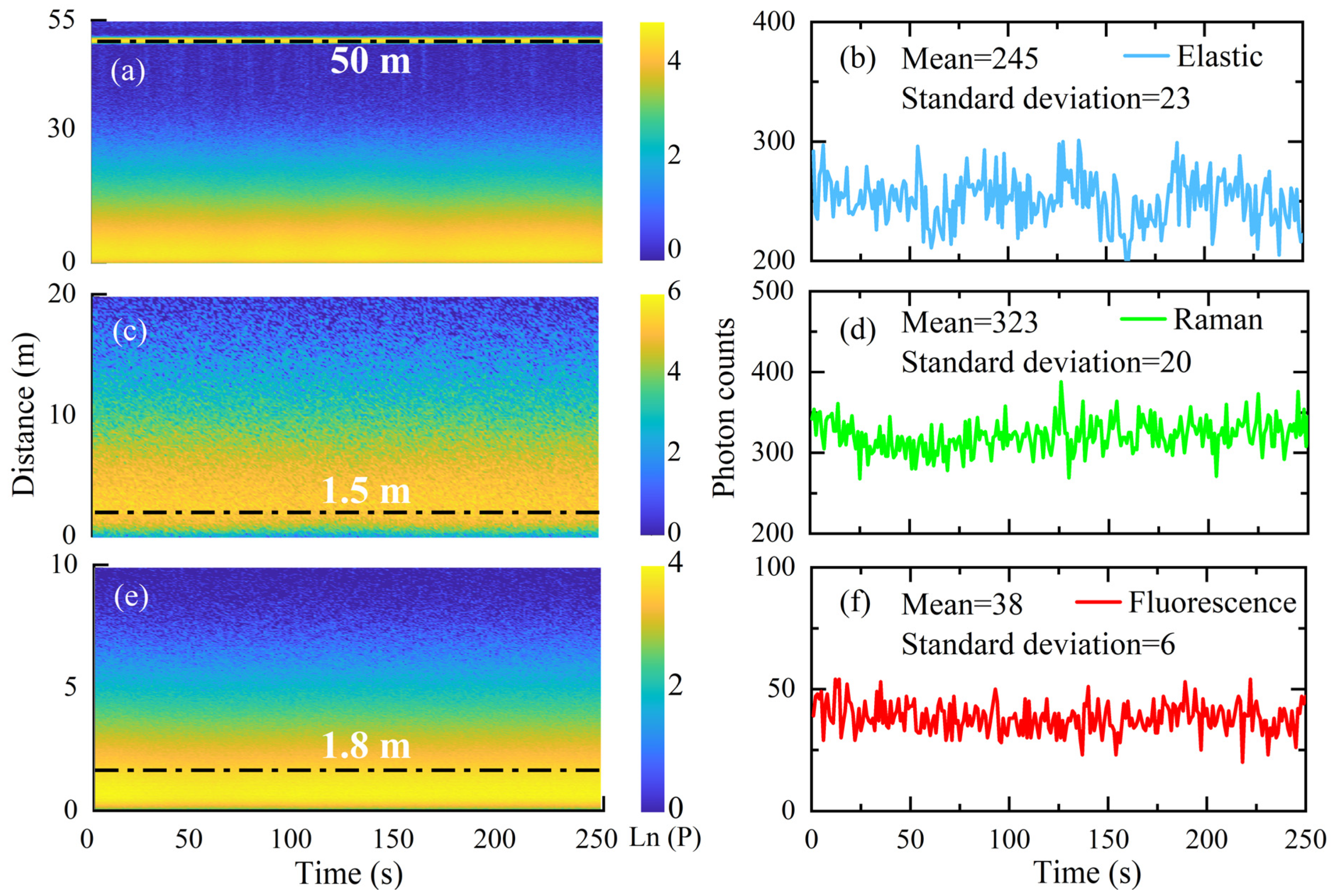
To assess the robustness of the MCAS, an experimental study was conducted using a single-photon underwater lidar system equipped with the MCAS. The experiment was carried out in a swimming pool at the Xiang’an campus of Xiamen University (24.37′N, 118.18′E). The size of the pool is 50 × 25 × 2 m3. After continuous observation for 300 s, the elastic, Raman and fluorescence signals of the water body were measured, and are shown in Figure 10.
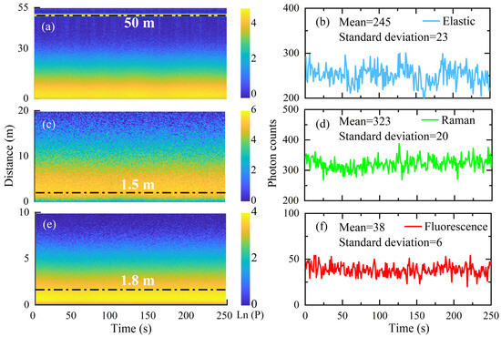
Figure 10.
The backscattered elastic (a), Raman (c), and fluorescence (e) signals obtained from the swimming pool experiment using the oceanic single-photon lidar equipped with the MCAS system. (b,d,f) The statistical results of the photon numbers in the corresponding positions of the three channels.
As shown in Figure 10a–c, the MCAS can reliably capture the elastic, Raman, and fluorescence backscattered signals from the single-photon underwater lidar. As shown in Figure 10b, the average photon count of the elastic signal at the swimming pool wall 50 m away from the lidar over a duration of 250 s is 245, with a standard deviation of 23. Similarly, Figure 10d illustrates that the average photon count of the Raman signal at a distance of 1.5 m from the lidar is 323, with a standard deviation of 20. Furthermore, Figure 10f demonstrates that the average photon count of the fluorescence signal at a distance of 1.8 m from the lidar is 38, with a standard deviation of 6. In the absence of significant noise, the photon counts collected by the underwater single-photon lidar follow a Poisson distribution. Furthermore, the elastic backscattered signal obtained through the elastic channel of the lidar is used to calculate the Klidar, using the slope method [42]. To mitigate the influence of geometric overlap on the inversion, the lidar backscattered signal is extracted from a range of 15 to 30 m, with a value of 0.07 m−1. In comparison, the in situ device AC-9 (WET Labs, Inc., Philomath, OR, USA) measures the coefficient c at 532 nm to be 0.072 m−1. These values are very close, validating that in situations with narrow FOV and small aperture, the measured Klidar tends towards c [41]. Additionally, the elastic signal reveals a strong echo signal from the swimming pool wall at approximately 55 m, demonstrating the potential of the underwater single-photon lidar for precise water depth detection and underwater target imaging. Moreover, the Raman signal can be utilized for the inversion of the particle beam attenuation coefficient [23]. Furthermore, the fluorescence backscattered signal will be used for the inversion of the absorption coefficient of phytoplankton (aph) at 532 nm and chlorophyll concentration in the water, which will be discussed in upcoming articles.
6. Conclusions
Underwater lidar is a crucial technology for marine sensing. The development of underwater lidar faces significant challenges due to limitations in volume and power consumption. In this work, a compact underwater lidar capable of operating at a depth of 1 km using single-photon detection technology is proposed. This advancement also brings new requirements for data acquisition cards utilized in single-photon underwater lidar systems.
To address this demand, this work proposes and demonstrates the MCAS, which combines coarse and fine time resolutions to meet the requirements of resolution and detection range for underwater single-photon lidar. Additionally, the work introduces histogram statistics into the MCAS, enabling lightweight communication data and suitable data storage. Furthermore, the study analyzes the periodic modulation caused by non-uniform phase shifts in the clock and proposes a code density method to address this issue. After conducting a lidar observation in a swimming pool, the experimental results confirm that the MCAS exhibits excellent stability.
In future work, a higher-resolution MCAS will be developed. Additionally, single-photon underwater lidar will be applied in various fields, including underwater optical parameter sensing, imaging and tracking of underwater targets, and mapping of deep-sea topography.
Author Contributions
Conceptualization, M.S.; methodology, M.S. and Z.L.; software, Z.L. and Z.Y.; validation, Z.L., F.C. and Z.Y.; formal analysis, Z.L. and Z.W.; investigation, Z.L. and Y.Q.; resources, M.S.; data curation, F.C.; writing—original draft preparation, Z.L. and M.S.; writing—review and editing, M.S. and Z.W.; visualization, Y.Q.; supervision, M.S.; project administration, M.S.; funding acquisition, M.S. All authors have read and agreed to the published version of the manuscript.
Funding
This research was funded by the National Key Research and Development Program of China (2022YFB3901704); the Innovation Program for Quantum Science and Technology (2021ZD0303102); the Fujian Provincial Central Guided Local Science and Technology Development Special Project (2022L3078); the Joint Funds of the National Natural Science Foundation of China (U2106210); the Natural Science Foundation of Fujian Province of China (2020J01026); and the MEL-RLAB Joint Fund for Marine Science & Technology Innovation.
Data Availability Statement
The data that support the findings of this study are available from the corresponding author upon reasonable request.
Conflicts of Interest
The authors declare no conflict of interest.
References
- Churnside, J.H. Review of profiling oceanographic lidar. Opt. Eng. 2014, 53, 051405. [Google Scholar] [CrossRef]
- Mandlburger, G.; Pfennigbauer, M.; Schwarz, R.; Flöry, S.; Nussbaumer, L. Concept and performance evaluation of a novel UAV-borne topo-bathymetric LiDAR sensor. Remote Sens. 2020, 12, 986. [Google Scholar] [CrossRef]
- Behrenfeld, M.J.; Hu, Y.; O’Malley, R.T.; Boss, E.S.; Hostetler, C.A.; Siegel, D.A.; Sarmiento, J.L.; Schulien, J.; Hair, J.W.; Lu, X. Annual boom–bust cycles of polar phytoplankton biomass revealed by space-based lidar. Nat. Geosci. 2017, 10, 118–122. [Google Scholar] [CrossRef]
- Zhang, S.; Chen, P.J. Subsurface phytoplankton vertical structure from lidar observation during SCS summer monsoon onset. Opt. Express 2022, 30, 17665–17679. [Google Scholar] [CrossRef]
- Fiorani, L.; Fantoni, R.; Lazzara, L.; Nardello, I.; Okladnikov, I.; Palucci, A.J. Lidar calibration of satellite sensed CDOM in the southern ocean. EARSeL eProc. 2006, 5, 89–99. [Google Scholar]
- Churnside, J.H. Lidar signature from bubbles in the sea. Opt. Express 2010, 18, 8294–8299. [Google Scholar] [CrossRef]
- Churnside, J.H.; Shaw, J.A. Lidar remote sensing of the aquatic environment. Appl. Opt. 2020, 59, C92–C99. [Google Scholar] [CrossRef] [PubMed]
- Liu, Q.; Wu, S.; Liu, B.; Liu, J.; Zhang, K.; Dai, G.; Tang, J.; Chen, G. Shipborne variable-FOV, dual-wavelength, polarized ocean lidar: Design and measurements in the Western Pacific. Opt. Express 2022, 30, 8927–8948. [Google Scholar] [CrossRef]
- Wang, D.; Xing, S.; He, Y.; Yu, J.; Xu, Q.; Li, P. Evaluation of a New Lightweight UAV-Borne Topo-Bathymetric LiDAR for Shallow Water Bathymetry and Object Detection. Sensors 2022, 22, 1379. [Google Scholar] [CrossRef]
- Li, K.; He, Y.; Ma, J.; Jiang, Z.; Hou, C.; Chen, W.; Zhu, X.; Chen, P.; Tang, J.; Wu, S. A dual-wavelength ocean lidar for vertical profiling of oceanic backscatter and attenuation. Remote Sens. 2020, 12, 2844. [Google Scholar] [CrossRef]
- Ma, Y.; Xu, N.; Liu, Z.; Yang, B.; Yang, F.; Wang, X.H.; Li, S. Satellite-derived bathymetry using the ICESat-2 lidar and Sentinel-2 imagery datasets. Remote Sens. Environ. 2020, 250, 112047. [Google Scholar] [CrossRef]
- Maccarone, A.; Drummond, K.; McCarthy, A.; Steinlehner, U.K.; Tachella, J.; Garcia, D.A.; Pawlikowska, A.; Lamb, R.A.; Henderson, R.K.; McLaughlin, S.; et al. Submerged single-photon LiDAR imaging sensor used for real-time 3D scene reconstruction in scattering underwater environments. Opt. Express 2023, 31, 16690–16708. [Google Scholar] [CrossRef] [PubMed]
- Shangguan, M.; Yang, Z.; Shangguan, M.; Lin, Z.; Liao, Z.; Guo, Y.; Liu, C. Remote sensing oil in water with an all-fiber underwater single-photon Raman lidar. Appl. Opt. 2023, 62, 5301–5305. [Google Scholar] [CrossRef] [PubMed]
- Shangguan, M.; Yang, Z.; Lin, Z.; Lee, Z.; Xia, H.; Weng, Z. Compact long-range single-photon underwater lidar with high spatial-temporal resolution. IEEE Geosci. Remote Sens. Lett. 2023, 20, 1501905. [Google Scholar] [CrossRef]
- Shangguan, M.; Xia, H.; Wang, C.; Qiu, J.; Shentu, G.; Zhang, Q.; Dou, X.; Pan, J.-W. All-fiber upconversion high spectral resolution wind lidar using a Fabry-Perot interferometer. Opt. Express 2016, 24, 19322–19336. [Google Scholar] [CrossRef]
- Shangguan, M.; Xia, H.; Wang, C.; Qiu, J.; Lin, S.; Dou, X.; Zhang, Q.; Pan, J.-W. Dual-frequency Doppler lidar for wind detection with a superconducting nanowire single-photon detector. Opt. Lett. 2017, 42, 3541–3544. [Google Scholar] [CrossRef] [PubMed]
- Yu, C.; Shangguan, M.; Xia, H.; Zhang, J.; Dou, X.; Pan, J.-W. Fully integrated free-running InGaAs/InP single-photon detector for accurate lidar applications. Opt. Express 2017, 25, 14611–14620. [Google Scholar] [CrossRef] [PubMed]
- Xia, H.; Shangguan, M.; Shentu, G.; Wang, C.; Qiu, J.; Zheng, M.; Xie, X.; Dou, X.; Zhang, Q.; Pan, J.-W. Brillouin optical time-domain reflectometry using up-conversion single-photon detector. Opt. Commun. 2016, 381, 37–42. [Google Scholar] [CrossRef]
- Shangguan, M.; Wang, C.; Xia, H.; Shentu, G.; Dou, X.; Zhang, Q.; Pan, J.-W. Brillouin optical time domain reflectometry for fast detection of dynamic strain incorporating double-edge technique. Opt. Commun. 2017, 398, 95–100. [Google Scholar] [CrossRef]
- Maccarone, A.; Mccarthy, A.; Ren, X.; Warburton, R.E.; Wallace, A.M.; Moffat, J.; Petillot, Y.; Buller, G.S. Underwater depth imaging using time-correlated single-photon counting. Opt. Express 2015, 23, 33911. [Google Scholar] [CrossRef] [PubMed]
- Maccarone, A.; Rocca, F.; Mccarthy, A.; Henderson, R.; Buller, G.S. Three-dimensional imaging of stationary and moving targets in turbid underwater environments using a single-photon detector array. Opt. Express 2019, 27, 28437–28456. [Google Scholar] [CrossRef] [PubMed]
- Shen, X.; Kong, W.; Chen, P.; Chen, T.; Huang, G.; Shu, R. A shipborne photon-counting lidar for depth-resolved ocean observation. Remote Sens. 2022, 14, 3351. [Google Scholar] [CrossRef]
- Shangguan, M.; Liao, Z.; Guo, Y.; Lee, Z. Sensing the profile of particulate beam attenuation coefficient through a single-photon oceanic Raman lidar. Opt. Express 2023, 31, 25398–25414. [Google Scholar] [CrossRef] [PubMed]
- Kim, M.-J.; Choi, J.-H.; Hong, D.G. Dose and dose rate dependence of time-resolved OSL from Korean paleosol quartz. Radiat. Meas. 2011, 46, 1518–1521. [Google Scholar] [CrossRef]
- Picoquant. Home. Accessed. Available online: https://www.picoquant.com/products/category/tcspc-and-time-tagging-modules (accessed on 23 September 2023).
- J.Smith. Time Tagger Series. Available online: https://www.swabianinstruments.com/time-tagger/ (accessed on 23 September 2023).
- IdQuantique. ID900 Time Controller. Accessed. 2019. Available online: https://www.spectra-line.com/uploads/20200410/b72ffd11ba3e25bdde788943f8899927.pdf (accessed on 23 September 2023).
- Wang, Y.; Kuang, P.; Liu, C. A 256-channel multi-phase clock sampling-based time-to-digital converter implemented in a Kintex-7 FPGA. In Proceedings of the 2016 IEEE International Instrumentation and Measurement Technology Conference Proceedings, Taipei, Taiwan, 23–26 May 2016; pp. 1–5. [Google Scholar]
- Lin, M.-C.; Tsai, G.-R.; Liu, C.-Y.; Chu, S.-S. FPGA-based high area efficient time-to-digital IP design. In Proceedings of the TENCON 2006-2006 IEEE Region 10 Conference, Hong Kong, China, 14–17 November 2006; pp. 1–4. [Google Scholar]
- Cheng, Z.; Zheng, X.; Deen, M.J.; Peng, H.J. Recent Developments and Design Challenges of High-Performance Ring Oscillator CMOS Time-to-Digital Converters. IEEE Trans. Electron Devices 2015, 63, 1–17. [Google Scholar] [CrossRef]
- Wang, Y.; Chong, L.J. A 4.2 ps Time-Interval RMS Resolution Time-to-Digital Converter Using a Bin Decimation Method in an UltraScale FPGA. IEEE Trans. Nucl. Sci. 2016, 63, 2632–2638. [Google Scholar] [CrossRef]
- Szplet, R.; Czuba, A. Two-Stage Clock-Free Time-to-Digital Converter Based on Vernier and Tapped Delay Lines in FPGA Device. Electronics 2021, 10, 2190. [Google Scholar] [CrossRef]
- Won, J.Y.; Kwon, S.I.; Yoon, H.S.; Ko, G.B.; Son, J.-W.; Lee, J.S. Dual-Phase Tapped-Delay-Line Time-to-Digital Converter With On-the-Fly Calibration Implemented in 40 nm FPGA. IEEE Trans. Biomed. Circuits Syst. 2016, 10, 231. [Google Scholar] [CrossRef]
- Wu, J. Several Key Issues on Implementing Delay Line Based TDCs Using FPGAs. IEEE Trans. Nucl. Sci. 2010, 57, 1543–1548. [Google Scholar] [CrossRef]
- Namba, A.K. A low area calibration technique of TDC using variable clock generator for accurate on-line delay measurement. In Proceedings of the International Symposium on Quality Electronic Design, Santa Clara, CA, USA, 2–4 March 2015. [Google Scholar]
- Wu, J.; Shi, Z. The 10-ps wave union TDC: Improving FPGA TDC resolution beyond its cell delay. In Proceedings of the IEEE Nuclear Science Symposium Conference Record, Dresden, Germany, 19–25 October 2008. [Google Scholar]
- Markovic, B.; Tisa, S.; Villa, F.A.; Tosi, A.; Zappa, F. A High-Linearity, 17 ps Precision Time-to-Digital Converter Based on a Single-Stage Vernier Delay Loop Fine Interpolation. IEEE Trans. Circuits Syst. I Regul. Pap. 2013, 60, 557–569. [Google Scholar] [CrossRef]
- Barton-Grimley, R.A.; Stillwell, R.A.; Thayer, J.P. High resolution photon time-tagging lidar for atmospheric point cloud generation. Opt. Express 2018, 26, 26030–26044. [Google Scholar] [CrossRef] [PubMed]
- Brewer, P.G.; Peltzer, E.T.; Walz, P.M.; Wojciechowicz, M. The speciation of water in sea water and in gelatinous marine animals. Mar. Chem. 2017, 195, 94–104. [Google Scholar] [CrossRef]
- Taniguchi, M.; Lindsey, J.S. Absorption and fluorescence spectral database of chlorophylls and analogues. Photochem. Photobiol. 2021, 97, 136–165. [Google Scholar] [CrossRef] [PubMed]
- Gordon, H.R. Interpretation of airborne oceanic lidar: Effects of multiple scattering. Appl. Opt. 1982, 21, 2996–3001. [Google Scholar] [CrossRef]
- Churnside, J.H.; Hair, J.W.; Hostetler, C.A.; Scarino, A.J. Ocean backscatter profiling using high-spectral-resolution lidar and a perturbation retrieval. Remote Sens. 2018, 10, 2003. [Google Scholar] [CrossRef]
Disclaimer/Publisher’s Note: The statements, opinions and data contained in all publications are solely those of the individual author(s) and contributor(s) and not of MDPI and/or the editor(s). MDPI and/or the editor(s) disclaim responsibility for any injury to people or property resulting from any ideas, methods, instructions or products referred to in the content. |
© 2023 by the authors. Licensee MDPI, Basel, Switzerland. This article is an open access article distributed under the terms and conditions of the Creative Commons Attribution (CC BY) license (https://creativecommons.org/licenses/by/4.0/).

