
The Use of a Stable Super-Resolution Generative Adversarial Network (SSRGAN) on Remote Sensing Images


Abstract
:1. Introduction
- (1)
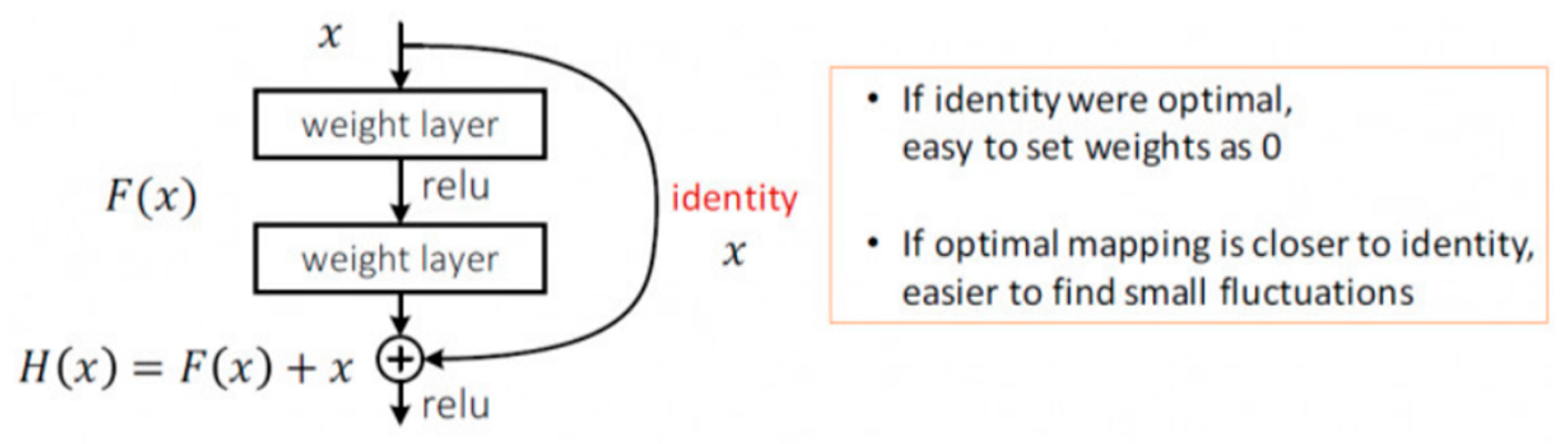
- We upgraded the generator’s network to ResNet-50, in which the basic residual blocks were switched to bottleneck blocks, so the generator can process more channels of information better and faster.
- (2)
- We added an additional fully connected (FC) layer in the discriminator part to further blend the features extracted, so the modified discriminator can work more steadily as a classifier.
- (3)
- We modified the loss function by changing the weight of regularization loss from 2 × 10⁻⁸ to 2 × 10⁻⁹, aiming to preserve more details.
2. Related Work
2.1. Remote Sensing Imaging Systems under Low-Light Conditions
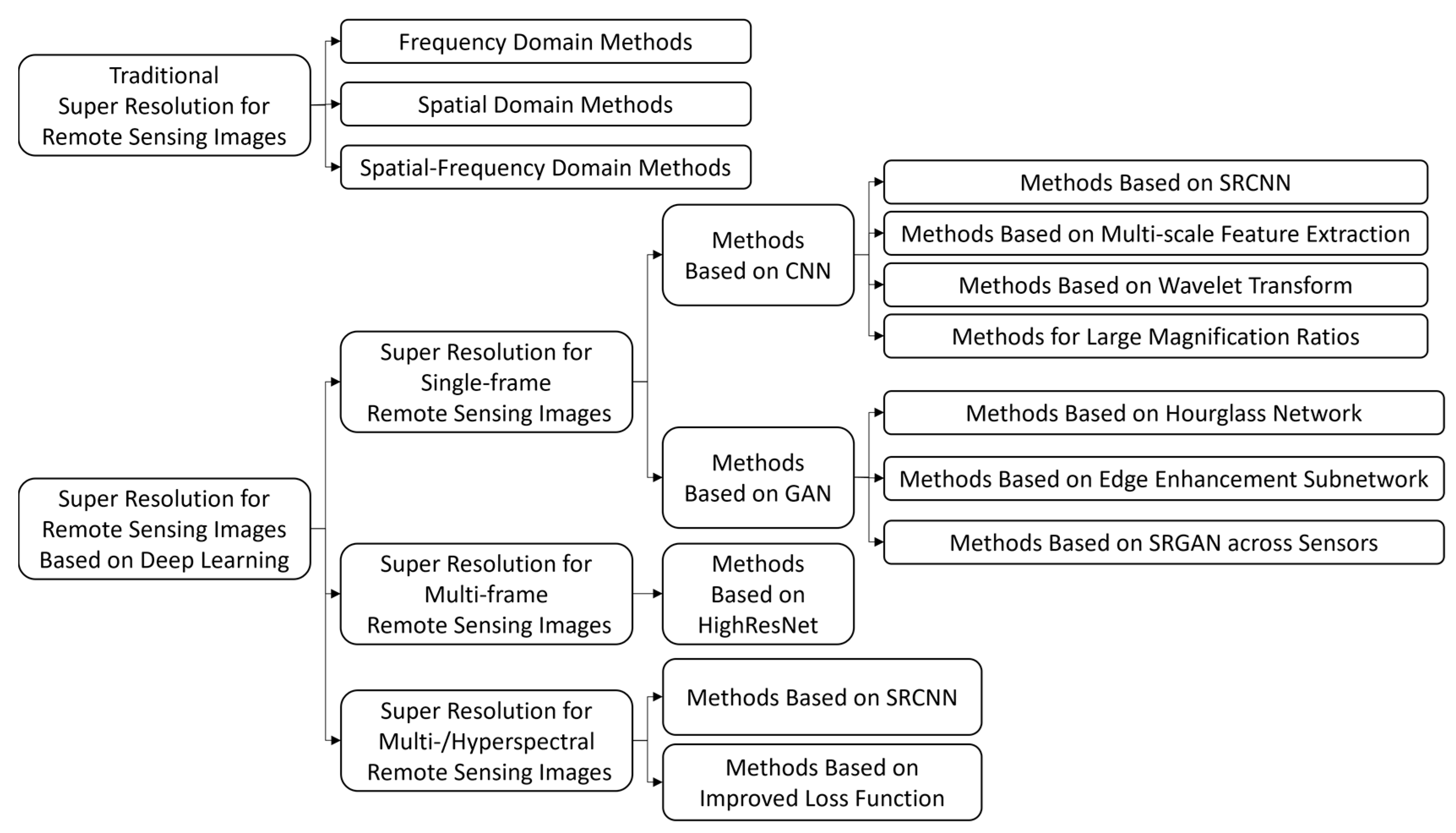
2.2. Super-Resolution in Remote Sensing Images
3. Methodology
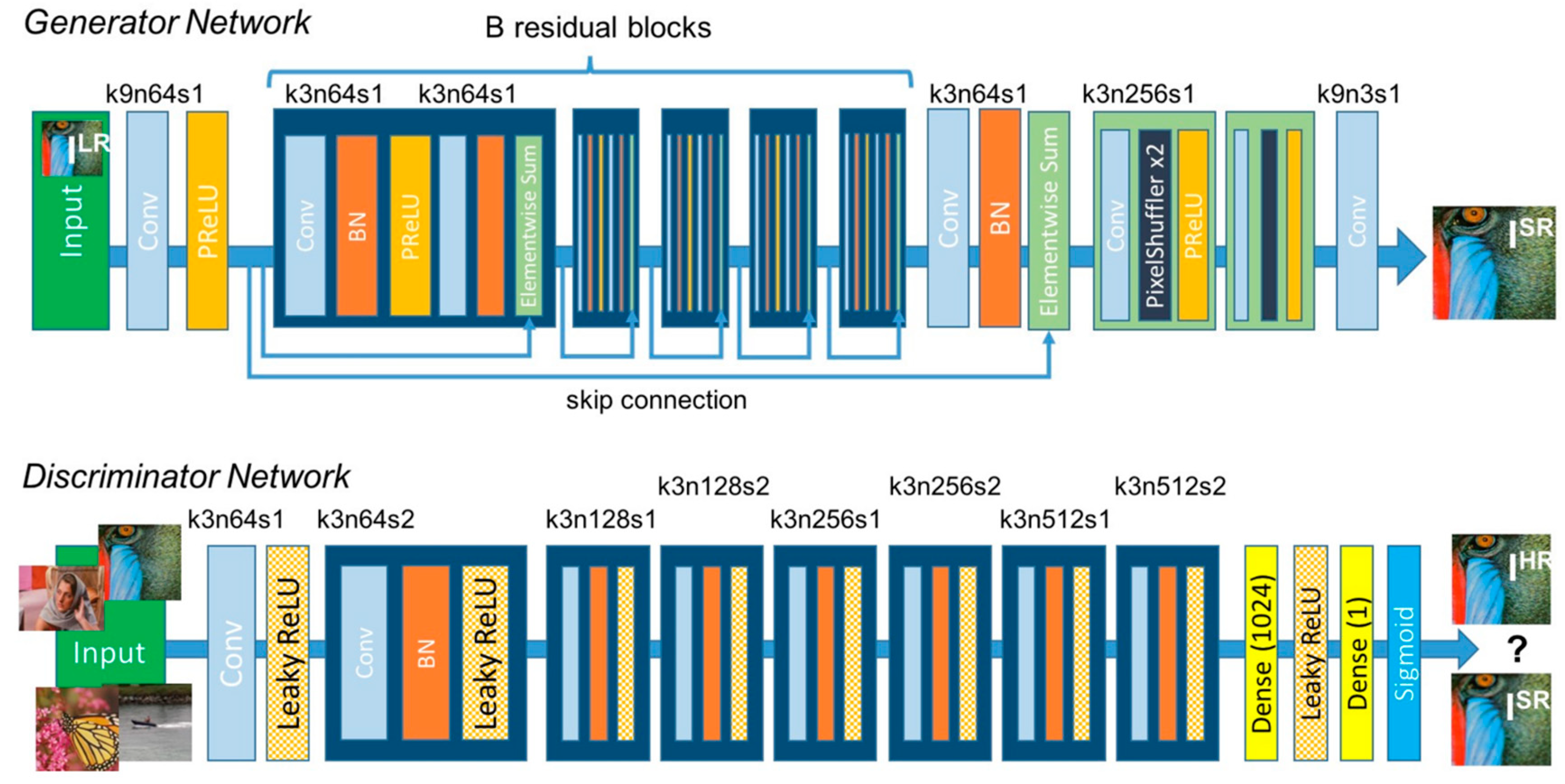
3.1. General Architecture: Generative Adversarial Network
3.2. Generator Model: ResNet-50
3.3. Discriminator Model: Truncated and Modified VGG-19
3.4. Loss Function
3.5. Optimizers: SGD and AdaGrad
4. Experimental Settings
4.1. Dataset
4.2. Evaluation Criteria
4.2.1. PSNR
4.2.2. SSIM
4.2.3. Time
5. Results
5.1. Training Process
5.2. Ablation Study
5.3. General Results Comparison
5.4. Comparison of Details
6. Discussion
7. Conclusions
Author Contributions
Funding
Data Availability Statement
Conflicts of Interest
References
- Gleyzes, M.A.; Perret, L.; Kubik, P. Pleiades System Architecture and Main Performances. ISPRS-Int. Arch. Photogramm. Remote-Sens. Spat. Inf. Sci. 2012, XXXIX-B1, 537–542. [Google Scholar] [CrossRef]
- Kubik, P.; Pascal, V.; Latry, C.; Baillarin, S. Pleiades Image Quality: From Users’ Needs to Products Definition. Proc. Spie Int. Soc. Opt. Eng. 2005, 20, 59780L. [Google Scholar]
- Chen, S.; Rice, C.; Philbrick, B.; Boyle, C.; Hauser, E.W. Integrated Remote Sensing and Visualization (Irsv) System for Transportation Infrastructure Operations and Management, Phase One, Volume 6. High Resolut. Aer. Photogr. 2009, 109, 42–45. [Google Scholar]
- Aoran, X.; Zhongyuan, W.; Lei, W.; Yexian, R. Super-resolution for “Jilin-1” Satellite Video Imagery via a Convolutional Network. Sensors 2018, 18, 1194. [Google Scholar] [CrossRef]
- Agustsson, E.; Timofte, R. NTIRE 2017 Challenge on Single Image Super-Resolution: Dataset and Study. In Proceedings of the 2017 IEEE Conference on Computer Vision and Pattern Recognition Workshops (CVPRW), Honolulu, HI, USA, 21–26 July 2017; IEEE: Piscataway, NJ, USA, 2017. [Google Scholar]
- Yang, D.; Li, Z.; Xia, Y.; Chen, Z. Remote sensing image super-resolution: Challenges and approaches. In Proceedings of the 2015 IEEE International Conference on Digital Signal Processing, Singapore, 21–24 July 2015; IEEE: Piscataway, NJ, USA, 2015. [Google Scholar]
- Dong, C.; Loy, C.; He, K.; Tang, X. Image super-resolution using deep convolutional networks. IEEE Trans. Pattern Anal. Mach. Intell. 2016, 38, 295–307. [Google Scholar] [CrossRef] [PubMed]
- Haut, J.; Fernandez-Beltran, R.; Paoletti, M.; Plaza, J.; Plaza, A.; Pla, F. A new deep generative network for unsupervised remote sensing single-image super-resolution. IEEE Trans. Geosci. Remote Sens. 2018, 56, 6792–6810. [Google Scholar] [CrossRef]
- Jiang, K.; Wang, Z.; Yi, P.; Wang, G.; Lu, T.; Jiang, J. Edge-enhanced GAN for remote sensing image super resolution. IEEE Trans. Geosci. Remote Sens. 2019, 57, 5799–5812. [Google Scholar] [CrossRef]
- Yue, L.; Shen, H.; Li, J.; Yuanc, Q.; Zhang, H.; Zhang, L. Image super resolution: The techniques, applications, and future. Signal. Proc. 2016, 128, 389–408. [Google Scholar] [CrossRef]
- Li, F.; Jia, X.; Fraser, D.; Lambert, A. Super resolution for remote sensing images based on a universal hidden Markov tree model. IEEE Trans. Geosci. Remote Sens. 2010, 48, 1270–1278. [Google Scholar]
- Pan, Z.; Yu, J.; Huang, H.; Hu, S.; Zhang, A.; Ma, H.; Sun, W. Super-resolution based on compressive sensing and structural self-similarity for remote sensing images. IEEE Trans. Geosci. Remote Sens. 2013, 51, 4864–4876. [Google Scholar] [CrossRef]
- Chavez-Roman, H.; Ponomaryov, V. Super resolution image generation using wavelet domain interpolation with edge extraction via a sparse representation. IEEE Geosci. Remote Sens. Lett. 2014, 11, 1777–1781. [Google Scholar] [CrossRef]
- Li, J.; Yuan, Q.; Shen, H. Hyperspectral image super-resolution by spectral mixture analysis and spatial–spectral group sparsity. IEEE Geosci. Remote Sens. Lett. 2016, 13, 1250–1254. [Google Scholar] [CrossRef]
- Yang, J.; Wright, J.; Huang, T.S.; Ma, Y. Image super-resolution via sparse representation. IEEE Trans. Image Proc. 2010, 19, 2861–2873. [Google Scholar] [CrossRef] [PubMed]
- Dong, W.; Zhang, L.; Shi, G.; Wu, X. Image deblurring and super-resolution by adaptive sparse domain selection and adaptive regularization. IEEE Trans. Image Proc. 2011, 20, 1838–1857. [Google Scholar] [CrossRef] [PubMed]
- Bengio, Y.; Courville, A.; Vincent, P. Representation learning: A review and new perspectives. IEEE Trans. Pattern Anal. Mach. Intell. 2013, 35, 1798–1828. [Google Scholar] [CrossRef] [PubMed]
- Krizhevsky, A.; Sutskever, I.; Hinton, G.E. ImageNet classification with deep convolutional neural networks. Proc. Adv. Neural Inf. Proc. Syst. 2012, 25, 1097–1105. [Google Scholar] [CrossRef]
- Girshick, R.; Donahue, J.; Darrell, T.; Malik, J. Rich feature hierarchies for accurate object detection and semantic segmentation. In Proceedings of the IEEE Conference on Computer Vision and Pattern Recognition (CVPR), Columbus, OH, USA, 23–28 June 2014; pp. 580–587. [Google Scholar]
- Zou, Z.; Shi, Z. Ship detection in spaceborne optical image with SVD networks. IEEE Trans. Geosci. Remote Sens. 2016, 54, 5832–5845. [Google Scholar] [CrossRef]
- Dong, C.; Loy, C.C.; Tang, X. Accelerating the super-resolution convolutional neural network. In Proceedings of the Computer Vision–ECCV 2016: 14th European Conference, Amsterdam, The Netherlands, 11–14 October 2016; pp. 391–407. [Google Scholar]
- Goodfellow, I.J.; Pouget-Abadie, J.; Mirza, M.; Xu, B.; Warde-Farley, D.; Ozair, S.; Courville, A.; Bengio, Y. Generative adversarial nets. In Proceedings of the 27th International Conference on Neural Information Processing Systems, Montreal, QC, Canada, 8–13 December 2014; Volume 1, pp. 2672–2680. [Google Scholar] [CrossRef]
- Ledig, C.; Theis, L.; Huszár, F.; Caballero, J.; Cunningham, A.; Acosta, A.; Aitken, A.; Tejani, A.; Totz, J.; Wang, Z.; et al. Photo-realistic single image super-resolution using a generative adversarial network. In Proceedings of the 2017 IEEE Conference on Computer Vision and Pattern Recognition (CVPR), Honolulu, HI, USA, 21–26 July 2017; pp. 105–114. [Google Scholar] [CrossRef]
- He, K.; Sun, J. Deep Residual Learning for Image Recognition. In Proceedings of the IEEE Conference on Computer Vision and Pattern Recognition, Las Vegas, NV, USA, 27–30 June 2016; pp. 770–778. [Google Scholar]
- Li, B.; Member, S.; He, Y. An Improved ResNet Based on the Adjustable Shortcut Connections. IEEE Access 2018, 6, 18967–18974. [Google Scholar] [CrossRef]
- Karras, T.; Laine, S.; Aittala, M.; Hellsten, J.; Lehtinen, J.; Aila, T. Analyzing and improving the image quality of stylegan. In Proceedings of the IEEE Computer Society Conference on Computer Vision and Pattern Recognition, Seattle, WA, USA, 13–19 June 2020; pp. 8107–8116. [Google Scholar] [CrossRef]
- Karras, T.; Laine, S.; Aila, T. A Style-Based Generator Architecture for Generative Adversarial Networks. IEEE Trans. Pattern Anal. Mach. Intell. 2021, 43, 4217–4228. [Google Scholar] [CrossRef] [PubMed]


| Criteria | Methods | |||
|---|---|---|---|---|
| SRGAN | SRGAN + G | SRGAN + D | Ours | |
| PSNR/dB | 32.5216 | 32.5815 | 32.5411 | 32.6847 |
| SSIM | 0.8776 | 0.8815 | 0.8903 | 0.8962 |
| Criteria | Methods | |||
|---|---|---|---|---|
| SRGAN | SRGAN + G | SRGAN + D | Ours | |
| PSNR/dB | 31.6962 | 31.7209 | 31.7341 | 31.8191 |
| SSIM | 0.8224 | 0.8299 | 0.8354 | 0.8434 |
| Criteria | Methods | |||
|---|---|---|---|---|
| SRGAN | SRGAN + G | SRGAN + D | Ours | |
| PSNR/dB | 30.3971 | 30.4547 | 30.4382 | 30.5095 |
| SSIM | 0.7912 | 0.8017 | 0.8065 | 0.8124 |
| Criteria | Methods | |||||
|---|---|---|---|---|---|---|
| Bicubic | SRCNN | VDSR | DRRN | DCSCN | Ours | |
| PSNR/dB | 30.0797 | 31.5459 | 31.8755 | 31.9316 | 32.0908 | 32.6847 |
| SSIM | 0.7794 | 0.8182 | 0.8759 | 0.8865 | 0.8392 | 0.8962 |
| Time/s | 0.1150 | 1.5595 | 0.5928 | 5.3689 | 4.1281 | 1.5223 |
| Criteria | Methods | |||||
|---|---|---|---|---|---|---|
| Bicubic | SRCNN | VDSR | DRRN | DCSCN | Ours | |
| PSNR/dB | 29.7451 | 30.6497 | 30.9601 | 31.0332 | 31.3711 | 31.8191 |
| SSIM | 0.7141 | 0.7558 | 0.8211 | 0.8293 | 0.7819 | 0.8434 |
| Time/s | 0.1097 | 1.4638 | 0.5967 | 5.2896 | 2.5328 | 1.0897 |
| Criteria | Methods | |||||
|---|---|---|---|---|---|---|
| Bicubic | SRCNN | VDSR | DRRN | DCSCN | Ours | |
| PSNR/dB | 28.6978 | 29.4622 | 30.0998 | 30.2242 | 30.3636 | 30.5095 |
| SSIM | 0.7232 | 0.7338 | 0.7927 | 0.7823 | 0.7711 | 0.8124 |
| Time/s | 0.1065 | 1.5107 | 0.9524 | 5.3167 | 2.3535 | 0.9947 |
Disclaimer/Publisher’s Note: The statements, opinions and data contained in all publications are solely those of the individual author(s) and contributor(s) and not of MDPI and/or the editor(s). MDPI and/or the editor(s) disclaim responsibility for any injury to people or property resulting from any ideas, methods, instructions or products referred to in the content. |
© 2023 by the authors. Licensee MDPI, Basel, Switzerland. This article is an open access article distributed under the terms and conditions of the Creative Commons Attribution (CC BY) license (https://creativecommons.org/licenses/by/4.0/).
Share and Cite
Pang, B.; Zhao, S.; Liu, Y. The Use of a Stable Super-Resolution Generative Adversarial Network (SSRGAN) on Remote Sensing Images. Remote Sens. 2023, 15, 5064. https://doi.org/10.3390/rs15205064
Pang B, Zhao S, Liu Y. The Use of a Stable Super-Resolution Generative Adversarial Network (SSRGAN) on Remote Sensing Images. Remote Sensing. 2023; 15(20):5064. https://doi.org/10.3390/rs15205064
Chicago/Turabian StylePang, Boyu, Siwei Zhao, and Yinnian Liu. 2023. "The Use of a Stable Super-Resolution Generative Adversarial Network (SSRGAN) on Remote Sensing Images" Remote Sensing 15, no. 20: 5064. https://doi.org/10.3390/rs15205064
APA StylePang, B., Zhao, S., & Liu, Y. (2023). The Use of a Stable Super-Resolution Generative Adversarial Network (SSRGAN) on Remote Sensing Images. Remote Sensing, 15(20), 5064. https://doi.org/10.3390/rs15205064