Article

Hyperspectral Image Super-Resolution Algorithm Based on Graph Regular Tensor Ring Decomposition

1
The School of Computer Science and Engineering, North Minzu University, Yinchuan 750021, China
2
The School of Electronic Engineering, Xidian University, Xi’an 710071, China
*
Author to whom correspondence should be addressed.
Remote Sens. 2023, 15(20), 4983; https://doi.org/10.3390/rs15204983
Submission received: 7 September 2023 / Revised: 12 October 2023 / Accepted: 12 October 2023 / Published: 16 October 2023

Abstract

:
This paper introduces a novel hyperspectral image super-resolution algorithm based on graph-regularized tensor ring decomposition aimed at resolving the challenges of hyperspectral image super-resolution. This algorithm seamlessly integrates graph regularization and tensor ring decomposition, presenting an innovative fusion model that effectively leverages the spatial structure and spectral information inherent in hyperspectral images. At the core of the algorithm lies an iterative optimization process embedded within the objective function. This iterative process incrementally refines latent feature representations. It incorporates spatial smoothness constraints and graph regularization terms to enhance the quality of super-resolution reconstruction and preserve image features. Specifically, low-resolution hyperspectral images (HSIs) and high-resolution multispectral images (MSIs) are obtained through spatial and spectral downsampling, which are then treated as nodes in a constructed graph, efficiently fusing spatial and spectral information. By utilizing tensor ring decomposition, HSIs and MSIs undergo feature decomposition, and the objective function is formulated to merge reconstructed results with the original images. Through a multi-stage iterative optimization procedure, the algorithm progressively enhances latent feature representations, leading to super-resolution hyperspectral image reconstruction. The algorithm’s significant achievements are demonstrated through experiments, producing sharper, more detailed high-resolution hyperspectral images (HRIs) with an improved reconstruction quality and retained spectral information. By combining the advantages of graph regularization and tensor ring decomposition, the proposed algorithm showcases substantial potential and feasibility within the domain of hyperspectral image super-resolution.

1. Introduction

Hyperspectral remote sensing is a specialized remote sensing technique employed to acquire hyperspectral image data pertaining to the Earth’s surface. Compared with traditional remote sensing images, hyperspectral remote sensing can provide richer spectral information by observing and collecting data in more narrow wavelength bands. It has a wide range of applications in the fields of earth science, environmental monitoring, agriculture, forestry, urban planning, etc. Hyperspectral remote sensing uses sensors capable of collecting data in dozens or hundreds of consecutive spectral bands. These bands typically cover the visible, near-infrared, and short-wave infrared frequency bands. The spectral response of each band can provide a spectral signature, allowing more information to be obtained from remotely sensed images. By analyzing and processing these hyperspectral data, more detailed and accurate information, such as ground features, material composition, and environmental parameters, is obtained. However, the spatial resolution and spectral resolution of hyperspectral images often cannot reach the ideal state at the same time, considering the limitations of solar incident energy and sensors. Therefore, a popular approach is to improve the spatial resolution of hyperspectral images by fusing multispectral images (MSIs) with hyperspectral images (HSIs). This fusion method can make full use of the higher spatial resolution of multispectral images and combine it with the rich spectral information of hyperspectral images to obtain images with both a high spatial resolution and rich spectral information.
In the field of hyperspectral images, image fusion has been extensively and intensively studied by many researchers. According to the three dimensions in which the fused data are located, image fusion can be classified into pixel-level fusion, feature-level fusion, and decision-level fusion. Panchromatic sharpening [1] was one of the first spatial–spectral fusion methods developed. This method fuses a panchromatic image with a high spatial resolution with a multispectral image with a low spatial resolution but with multiple spectral bands. The panchromatic image has only one spectral band but a high spatial resolution, while the multispectral image contains rich spectral information, although it has a low spatial resolution. Via the panchromatic sharpening method, an image with both high spatial resolution containing multiple spectral bands can be obtained. This fusion method has an important role in the field of remote sensing and can provide more accurate and comprehensive information for various applications.
Pixel-level fusion methods are classified as component replacement (CS) [2,3,4], multi-resolution analysis (MRA) [5,6], hybrid methods [7,8], and model-based methods. These methods include intensity hue saturation (IHS) [9,10] methods, the Brovey transform [11], principal component analysis (PCA) [12], Gram–Schmidt (GS) [13] orthogonalization, the Laplace pyramid [14], the curvelet transform [15], and sparse matrix decomposition [16]. However, with the introduction of more algorithms and experiments, researchers have found some limitations of traditional methods to solve the problem of the hyper-resolution of hyperspectral images.
With the continuous development of model-based methods, researchers are increasingly focused on matrix-based decomposition [17,18,19,20,21] and tensor-based decomposition [22,23,24,25] methods. Common tensor decomposition methods include matrix decomposition, CP decomposition (CANDECOMP/PARAFAC) [26,27], Tucker decomposition [28,29], Tensor Train decomposition [30,31], and tensor ring decomposition [32,33,34]. These methods are receiving increasing attention and have more applications in the field of hyperspectral image super-resolution. A matrix can be viewed as a two-dimensional tensor, and therefore matrix decomposition can also be viewed as two-dimensional tensor decomposition.
Naoto Yokoya et al. [35] proposed a fusion method for hyperspectral and multispectral data called Coupled Non-negative Matrix Factorization (CNMF). This approach decomposes both types of data into endmember matrices and abundance matrices through unsupervised unmixing, resulting in a high-resolution hyperspectral image. However, CNMF is an ill-posed inverse problem and requires the addition of regularization terms to enhance its effectiveness. Some researchers have made improvements to CNMF. For instance, Yang et al. [36] introduced endmember vertex distance and iterative centroid proximity regularization terms, incorporating sparse and proximal regularization terms into CNMF. This approach reduces the computational complexity through proximal alternating optimization. Simões et al. [37] proposed the HySure method, which uses subspace regularization and vector total variation to effectively address the fusion of multispectral and panchromatic images. Dian et al. [38] utilized clustering structures to propose a low-dimensional spectral subspace representation model, which effectively captures the self-similarity of hyperspectral images and enhances image reconstruction. Xue et al. [21] developed a subspace clustering method based on structured sparse low-rank representation, where data samples are expressed as linear combinations of a dictionary and a basis matrix. This approach leverages learned spatial and spectral low-rank structures for hyperspectral image super-resolution.
However, in terms of computational efficiency and cost-effectiveness, tensor decomposition methods have shown unique advantages compared to matrix factorization methods. They comprehensively capture both spatial and spectral information in hyperspectral images. This comprehensiveness allows tensor decomposition to excel in preserving image details and features, thereby improving image resolution and information recovery capabilities.
Prévost et al. [39] proposed a new method for hyperspectral super-resolution (Coupled Tucker Approximation: Recoverability and SVD-Based, SCOTT), which is based on a coupled low-rank multicollinear (Tucker) model, using low-rank tensor approximation for hyperspectral super-resolution reconstruction of images. To implement the coupled tensor approximation, they proposed two SVD-based algorithms that are simple and efficient for dealing with unknown spatial degradation and generalized sharpening. By optimizing these algorithms, more accurate super-resolution reconstruction results of hyperspectral images can be obtained. Kanatsoulis et al. [40] proposed a new framework based on coupled tensor factorization (STEREO). This method aims to identify the super-resolution tensor and is suitable for dealing with cases where the spatial degradation model is unclear or inaccurately estimated. By optimizing this framework, the super-resolution reconstruction of hyperspectral images can be improved.
Dian et al. [41] introduced the non-local sparse tensor factorization (NLSTF) method to address hyperspectral image super-resolution. They treated hyperspectral data as a three-way tensor and applied Tucker decomposition techniques while incorporating the non-local similarity prior to hyperspectral images. This approach combines sparse tensor decomposition and non-local means into a unified framework, comprehensively addressing the issues of dictionary estimation and the sparse core tensor of each cube. This innovative method has brought new insights and solutions to the field of hyperspectral image super-resolution. Zeng et al. [25] investigated a multi-modal core tensor factorization (MCTF) method, which combines tensor low-rank modeling with a non-convex relaxation form (NC-MCTF). This model integrates the low-rank information provided by the Tucker and T-SVD methods, enabling simultaneous modeling of low-rank structures in multiple spectral directions and accurately recovering the intrinsic low-rank structural data using a small number of observed entries.
In summary, these methods make full use of tensor decomposition techniques to handle the multi-dimensional information in hyperspectral images, providing powerful tools and approaches for the field of hyperspectral image processing. In recent years, with the in-depth study of high-dimensional tensors, methods based on tensor chains and tensor rings have gradually emerged and gained popularity. These methods offer valuable insights and directions for future research in hyperspectral image processing.
In 2019, Dian [42] introduced a prior model based on the low tensor sequence rank, learning the correlations among spatial, spectral, and non-local modes in an HR-HSI cube with non-local similarity. This method transformed the super-resolution problem into a tensor chain rank regularization optimization problem. Jin et al. [23] employed a fully connected coupled tensor network to decompose the spatial structure of high-order tensors and used graph regularization techniques to preserve spectral information, thus improving the quality of the image.
Zhao et al. [43] first introduced the tensor ring decomposition (TR) model in 2016 based on the basic tensor decomposition model, which represents a high-dimensional tensor as a third-order tensor with cyclic interconnection properties by performing cyclic linear product operations on a low-dimensional core, and at the same time uses a graphical interpretation of it. The research focuses on how the properties of multilinear algebra can be effectively utilized by performing direct operations on TR representations (i.e., cores). This provides a potentially powerful framework for dealing with large-scale data. Additionally, it explores the connections with other tensor decomposition models, allowing for easy migration of potential representations from traditional models to TR models.
The coupled tensor ring model for hyperspectral image super-resolution problem was proposed by He et al. [44]. The model combines the advantages of coupling matrix and Tucker factorization and can better exploit the global spectral low-rank properties of recovered high-resolution hyperspectral images by using the kernel normalization tensor of the third core. The model has been shown to perform better in exploiting the low-rank properties of different hyperspectral image classes. By optimizing the CTRF model, accurate super-resolution reconstruction of hyperspectral images can be achieved, thus improving the spatial resolution and the quality of spectral information of the images.
Chen et al. [34] proposed an efficient FSTRD method to reconstruct HR-HSIs from an LR-HSI and HR-MSI pair of the same scene. The method introduces a smooth regularization term to constrain the factors in the tensor ring decomposition to capture the spatial–spectral continuity of HR-HSIs. Meanwhile, a PAM (Projected Alternating Minimization) algorithm was used to optimize each factor. Through the optimization process, the FSTRD method can effectively reconstruct the high-resolution hyperspectral images (HRIs) and improve the spatial resolution and spectral continuity of the images.
Despite the promising future of tensor ring decomposition methods in the field of hyperspectral image super-resolution, they still face several challenges and problems, which include difficulties in overfitting problems, real dataset validation, and noise interference. This paper presents a new algorithm for super-resolution of hyperspectral images based on graph-regular tensor ring decomposition. The contributions of the proposed method are as follows.
(1)
The graph regularization term is introduced, and the symmetric normalized Laplacian matrix is used to constrain the model, which provides a better structure representation and feature extraction ability for the model. This optimization method can not only effectively improve the structure and feature representation of the image, but also make full use of the spatial and spectral information in the process of image reconstruction, so as to preserve the key details and edge information.
(2)
By introducing a spatial smoothness constraint term, the paper successfully achieves spatial smoothness in the reconstructed images. This constraint not only preserves the textures and structural characteristics of the images but also effectively addresses overfitting and optimization oscillations. As a result, it ensures the stability and quality of the hyperspectral image super-resolution algorithm, providing a safeguard for its performance.
(3)
This method is based on tensor ring decomposition, fully utilizing the dual characteristics of hyperspectral images’ spatial structure and spectral information. By constructing a graph model and applying regularization techniques, it effectively captures both local and global features of the image, while also successfully preserving the spectral information. This enables achieving more comprehensive and accurate image reconstruction in the context of super-resolution.
(4)
The model proposed in this paper employs a multi-stage optimization framework, wherein the results of tensor ring decomposition are iteratively refined concurrently with the integration of regularization constraints. This multi-stage optimization strategy enhances the convergence and stability of the model, thereby yielding more precise and dependable super-resolution outcomes.
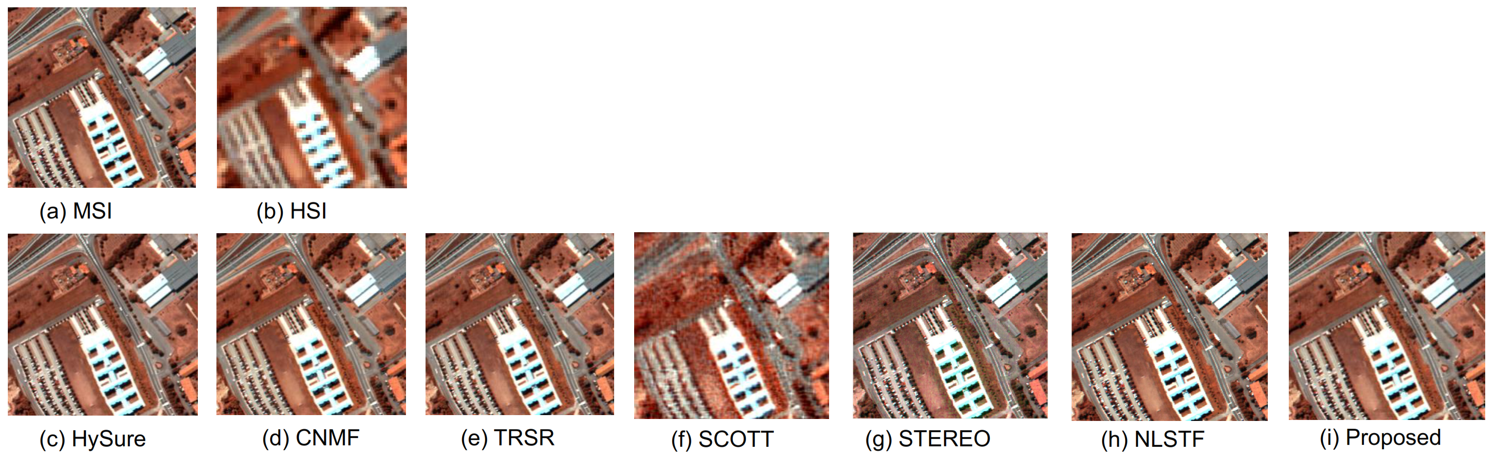
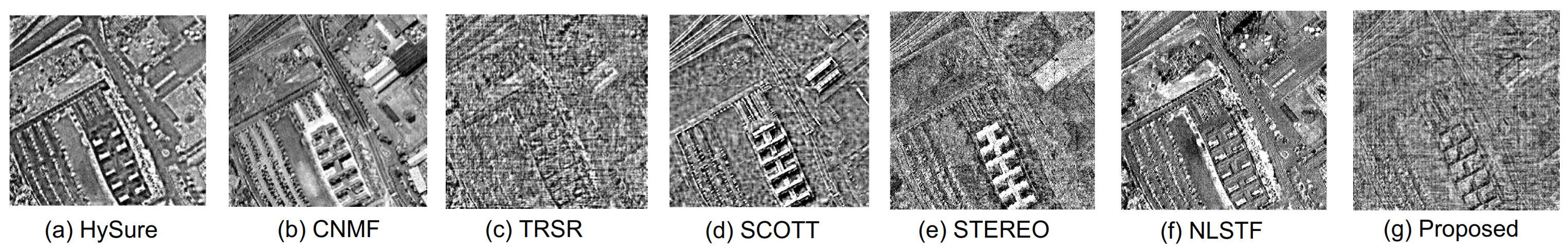
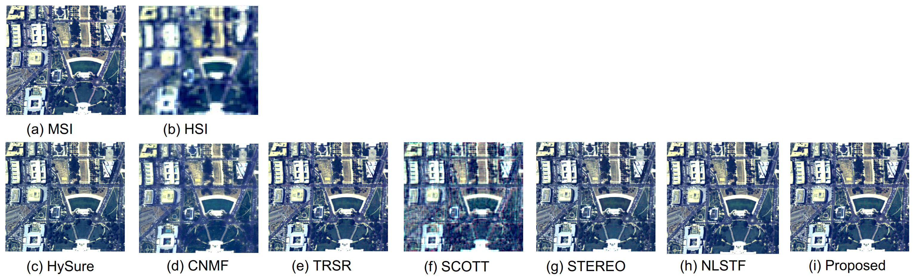
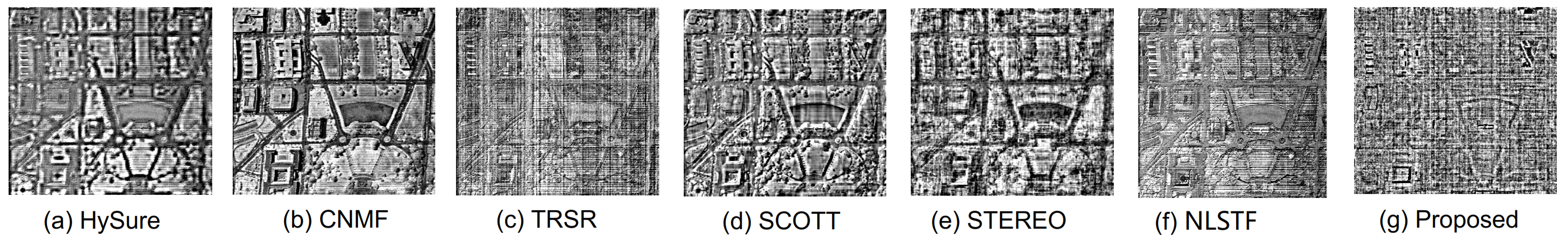
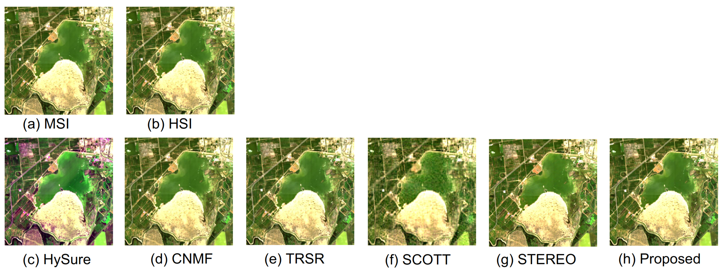
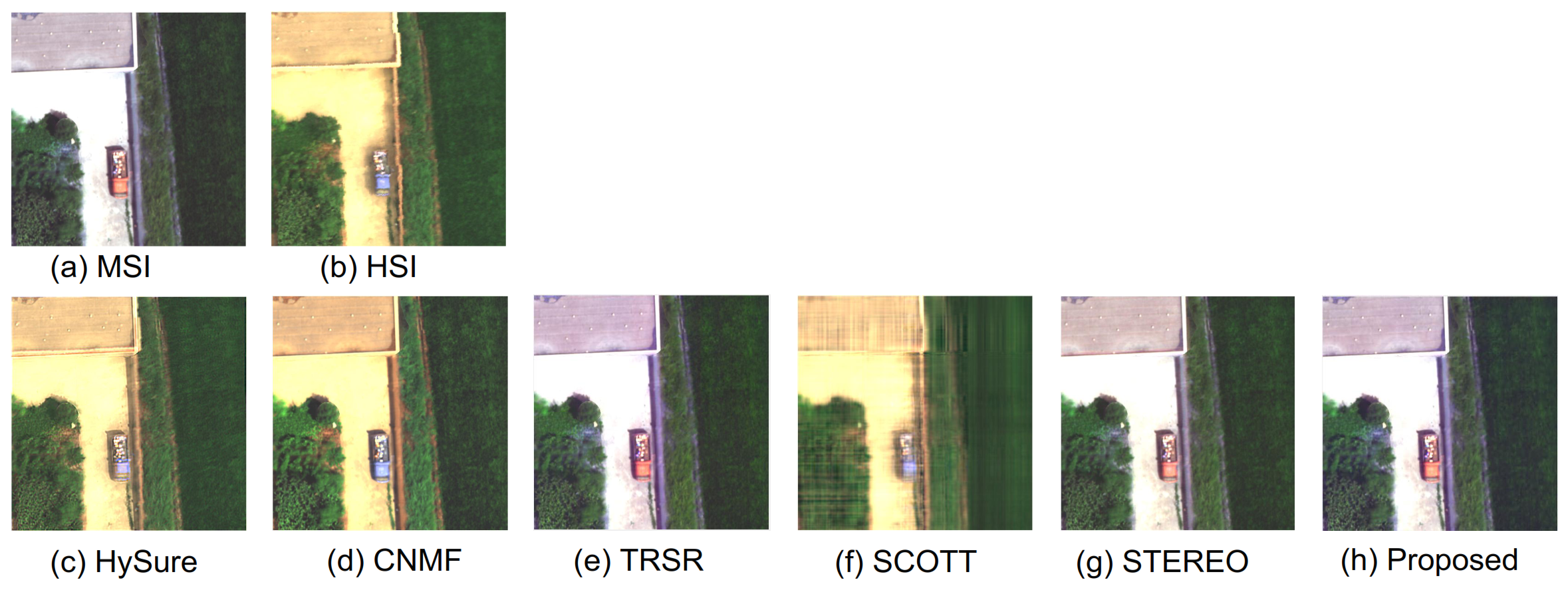
The algorithm in this paper has been experimentally demonstrated to achieve a significant improvement in the hyper-resolution task of hyperspectral images. Compared with traditional methods, our proposed algorithm not only produces clearer, detail-rich high-resolution images but also effectively retains the spectral information, particularly evident in real datasets. Therefore, the hyperspectral image super-resolution algorithm based on graph regular tensor ring decomposition has a broad potential and feasibility in practical applications.
The rest of the paper is organized according to the following structure. Section 2 provides the background information of the paper and details the hyperspectral image super-resolution algorithm (GRTR) based on graph regular tensor ring decomposition. Section 3 describes the optimization process of the GRTR algorithm in detail. Section 4 presents and analyzes the experimental results. Experimental evaluations are performed using multiple hyperspectral image datasets and compared with other classical methods. The performance of different algorithms in terms of spatial resolution enhancement and spectral fidelity is analyzed, and the quality of the reconstructed images is quantitatively evaluated. Finally, Section 5 summarizes the advantages and limitations of the GRTR algorithm and discusses possible future directions for improvement.

2. Background

2.1. Symbolic Representation

In this paper, the higher-order tensor is denoted using a calligraphic letter, X R N 1 × N 2 × . . . × N n denotes a tensor of order n, and N n denotes the size of the nth dimension. The third-order tensor, matrix, and vector are represented by the cursive letter X R N 1 × N 2 × N 3 , the upper-case letter X R N 1 × N 2 , and the lower-case letter x R N 1 , respectively.
The high-resolution hyperspectral images is defined as the third-order tensor X , X R N W × N H × N S , the low-resolution hyperspectral image (HSI) is defined as Y R N w × N h × N S , and the high-resolution multispectral image (MSI) is defined as Z R N W × N H × N s , where N W and N w denote the magnitude of the broad mode, 0 < N w < N W , N H and N h denote the magnitude of the high mode, 0 < N h < N H , N S and N s denote the magnitude of the spectral mode, 0 < N s < N S . X × n X represents the product of the tensor X and the matrix X in the nth mode. The three-state expansion of the third-order tensor is denoted as
X ( 1 ) = [ X ( : , : , 1 ) T , X ( : , : , 2 ) T , . . . , X ( : , : , N S ) T ] R N W × N S N H ,
X ( 2 ) = [ X ( : , : , 1 ) T , X ( : , : , 2 ) T , . . . , X ( : , : , N S ) T ] R N H × N W N S ,
X ( 3 ) = [ X ( : , 1 , : ) T , X ( : , 2 , : ) T , . . . , X ( : , N H , : ) T ] R N S × N W N H .

2.2. Tensor Decomposition

A tensor represents an abstraction of a multilinear mapping. It is an extension of a multidimensional array or multidimensional vector that can be used to represent a linear relationship between multiple vectors, matrices, or higher dimensional arrays. A tensor can be thought of as a multidimensional object that can have any number of dimensions, each of which can have an arbitrary size. The dimensions describe how the elements in the tensor are arranged, while the size of the tensor indicates the number of elements in each dimension. Common tensor decomposition methods include CP decomposition, Tucker decomposition, Tensor Train decomposition, and tensor ring decomposition.
CP decomposition [45] is a basic tensor decomposition method that decomposes a high-dimensional tensor into the product of multiple low-dimensional tensors. In hyperspectral image fusion, CP decomposition can decompose a hyperspectral image into three tensors that represent the relationship of spectra, space, and data, respectively, and each sub-tensor has rank 1 in a single dimension. The mathematical representation of CP decomposition is
X = r = 1 R a r b r c r .
where R is the magnitude of tensor rank, and the three sub-tensors are multiplied in the form of the outer product. A = a 1 , a 2 , . . . , a r , B = b 1 , b 2 , . . . , b r , and C = c 1 , c 2 , . . . , c r denote low-order potential factors, so CP decomposition can also be denoted as
X = A , B , C .
Although CP decomposition is concisely expressed, determining its rank is an NP-hard problem, making it challenging to ascertain the magnitude of the tensor rank.
Tucker decomposition [46], also known as higher-order singular value decomposition (HOSVD), is a widely used higher-order tensor decomposition method, which decomposes a tensor into the product of a kernel tensor and multiple factor tensors. In hyperspectral image fusion, Tucker decomposition can decompose a hyperspectral image into a core tensor and multiple factor tensors. Each factor tensor represents different features, such as spectral, spatial, etc. The expression of Tucker decomposition is
X = G × 1 A ( 1 ) × 2 A ( 2 ) × 3 A ( 3 ) .
where G R N w × N h × N s represents the core tensor, A ( 1 ) R N W × N w and A ( 2 ) R N H × N h represent the spatial feature tensor, and A ( 3 ) R N S × N s represents the spectral feature tensor.
Tensor Train decomposition [47] processes higher-order tensors by decomposing them into a product of multiple small kernel tensors. In hyperspectral image fusion, Tensor Train decomposition can decompose a hyperspectral image into multiple small kernel tensors. Each kernel tensor represents features like spectra, space, and so on. The expression of Tensor Train decomposition is
X ( i 1 , i 2 , i 3 ) = G ( 1 ) ( : , i 1 , : ) G ( 2 ) ( : , i 2 , : ) G ( 3 ) ( : , i 3 , : ) .
where G ( 1 ) R R 1 × N W × R 2 , G ( 2 ) R R 2 × N H × R 3 , G ( 3 ) R R 3 × N S × R 1 . The rank of Tensor Train is defined as r a n k T T ( X ) = ( R 1 , R 2 , R 3 ) , R 1 = R 3 = 1 .

2.3. Tensor Ring Decomposition

Tensor ring decomposition is a method that represents higher-order tensors as a ring product of a series of lower-order tensors. It is an extension and improvement of traditional tensor decomposition methods such as CP decomposition and Tucker decomposition. In tensor ring decomposition, the original high-dimensional tensor is represented as a ring structure consisting of multiple low-dimensional tensors. Each low-dimensional tensor represents the projection of the original tensor onto a particular mode. By interconnecting these low-dimensional tensors, the original tensor can be recovered. The expression of tensor ring decomposition is
X ( i 1 , i 2 , i 3 ) = t r ( G ( 1 ) ( : , i 1 , : ) G ( 2 ) ( : , i 2 , : ) G ( 3 ) ( : , i 3 , : ) ) .
where t r ( · ) denotes the matrix trace multiplication. The rank of the tensor ring is defined as r a n k T R ( X ) = ( R 1 , R 2 , R 3 ) , R 1 = R 3 . G ( n ) is the nth transverse slice matrix of the core tensor G ( n ) , so the HRI under the tensor ring decomposition can also be expressed as
X = Φ ( G ( 1 ) , G ( 2 ) , G ( 3 ) ) .
where G ( 1 ) R 1 × N W × R 2 , G ( 2 ) R 2 × N H × R 3 , and G ( 3 ) R 2 × N S × R 3 . The matrix representation of the TR can be expressed as X < n > = G ( 2 ) n ( G < 2 > n ) T . The main advantage of tensor ring decomposition is its ability to handle high-dimensional data efficiently and keep the storage and computational complexity low. It also has better local representation performance to capture the local structure and dependencies in high-dimensional data so that it can efficiently process high-dimensional data and extract useful information.

2.4. Graph Regularization

Graph regularization [48] is a graph-theory-based regularization method for processing data with a graph structure, such as social networks, images, videos, speech, etc. Its main aim is to improve the performance of a model by introducing structural information from the graph into the model. It is based on the concept of graph theory by establishing connection relations between data samples and using these connection relations to enhance the performance and robustness of the learning algorithm.
For a graph, G = ( V , E ) , where V is the set of vertices and E is the set of edges, let W be a symmetric weight matrix whose elements W ( i , j ) denote the weights of the edges between vertices i and j. Define the degree matrix D to be a diagonal matrix whose element D ( i , i ) denotes the degree of vertex i (the sum of the weights of the edges connected to it). The symmetric normalized Laplace matrix L s y m is defined as:
L s y m = D 1 / 2 ( D W ) D 1 / 2 = I D 1 / 2 W D 1 / 2 .
I is the unit matrix, and D 1 / 2 is the matrix obtained by calculating the positive square root of all elements of D. The symmetric normalized Laplace matrix L s y m has the following characteristics: Symmetry— L s y m is a symmetric matrix, i.e., L s y m ( i , j ) = L s y m ( j , i ) . Normalization— L s y m is normalized by the normalization of the degree matrix, such that the weights corresponding to the degrees of each vertex are normalized.
In this paper, the spatial map of X is denoted as G S P A = ( V S P A , E S P A ) , and the normalized spatial Laplace matrix with respect to the graph G S P A can be denoted as
L S P A = D S P A 1 / 2 ( D S P A W S P A ) D S P A 1 / 2 = I S P A D S P A 1 / 2 W S P A D S P A 1 / 2 .
The spectral map of X is denoted as G S P E = ( V S P E , E S P E ) , and the normalized spatial Laplace matrix with respect to the graph can be denoted as
L S P E = D S P E 1 / 2 ( D S P E W S P E ) D S P E 1 / 2 = I S P E D S P E 1 / 2 W S P E D S P E 1 / 2 .
where I S P A and I S P E are unitary matrices with matching sizes.
L S P A focuses on the similarity between pixels in a local region, which can be defined based on the distance between pixels or other similarity metrics, and thus it is able to capture spatial features such as textures, details, and edges in an image. By constraining L S P A , the super-resolution algorithm is able to better preserve and reconstruct the spatial features of the image, resulting in a clearer and more detailed synthetic high-resolution image. The L S P E can capture the spectral features in the image, i.e., the correlation and consistency between different bands. By constraining L S P E , the super-resolution algorithm ensures that the synthesized high-resolution image is consistent with the original image in terms of spectral features, thus preserving the color accuracy and spectral detail of the image. Collectively, the spatial constraint term L S P A plays a role in preserving and reconstructing spatial attributes like texture, details, and edges within an image. Similarly, the spectral constraint term L S P E contributes to upholding the spectral precision and consistency of an image. The amalgamation of these two constraint terms synergistically enhances the reconstruction prowess of the hyperspectral image super-resolution algorithm, resulting in synthesized high-resolution images that are more faithful and accurate in representation.
Graph regularization involves constructing a graph for the hyperspectral image, which models the relationships between adjacent pixels. These relationships can encompass spatial positions, spectral similarities, and more. By introducing regularization terms defined on the graph, the output of the super-resolution algorithm can be constrained, promoting smoother and more coherent high-resolution images in both spatial and spectral aspects. Additionally, graph regularization helps maintain the image’s structural and textural features, preventing the generation of overly smooth or distorted images.
The objective of hyperspectral image super-resolution is to recover a high-resolution image from a low-resolution hyperspectral image, aiming to enhance image details and spatial resolution. Graph regularization, on the other hand, harnesses the spatial and spectral characteristics within hyperspectral images and leverages the connections within the constructed graph. By doing so, it introduces additional constraints and prior information to enhance the performance of super-resolution algorithms.

2.5. Spatial Smoothing Constraints

Spatial smoothing constraint is a regularisation constraint method commonly used in image processing and computer vision tasks. It achieves the smoothing of an image by constraining the neighboring pixels of the image and limiting the gradient change of the image. For an image G , the spatial smoothing constraint on it is denoted as
Ψ d ( G ) = j = 1 N H { m , n } Ω G j ( m ) G j ( n ) 2
In this context, Ω represents the set of all pairs of neighboring elements in the graph G . The matrix G is derived by unfolding G in accordance with the spectral mode, where G j ( m ) signifies the mth element of the jth column. A diminished value of the smoothness constraint term suggests a decrease in differences between adjacent pixels in the image, producing smoother transitions and preserving the innate textures and structural attributes. Moreover, this results in a reduction in the potential noise and irregularities within the image. By incorporating the spatial smoothing constraint, a standard of smoothness is imposed on the output. This constraint compels the model to generate results that are more uniform and streamlined. Such a method not only diminishes the likelihood of overfitting due to noise or localized details in the training dataset but also stabilizes the optimization process. This stability enhances the possibility of the model arriving at a globally optimal solution or a more desirable local optimum, ultimately refining the generalization capabilities and optimization outcomes.

2.6. Proposed Method

In the context of hyperspectral image super-resolution, the relationship between HSRs and HSIs can be understood as arising from spatial downsampling. Specifically, a HRI undergoes downsampling operations along both spatial dimensions, resulting in the creation of an HSI. Thus, we can express the generation relationship of HSIs as follows:
Y = Φ ( G ( 1 ) × 2 U 1 , G ( 2 ) × 2 U 2 , G ( 3 ) )
where Y represents the HSI, and U 1 R N w × N W and U 2 R N H × N h are spatial downsampling matrices. Similarly, MSIs can be seen as obtained through spectral downsampling.
Thus, MSIs can be represented as follows:
Z = Φ ( G ( 1 ) , G ( 2 ) , G ( 3 ) × 2 U 3 )
where Z represents the MSI and U 3 R N S × N s represents the spectral downsampling matrix.
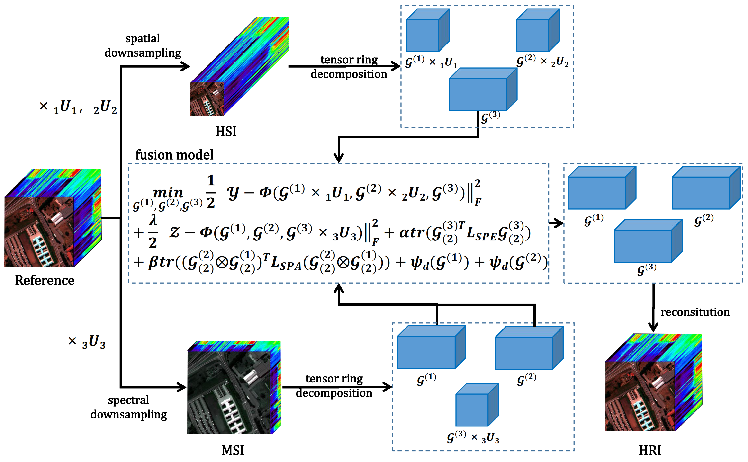
The hyperspectral image super-resolution algorithm based on graph-regularized tensor ring decomposition integrates the concepts of graph regularization and tensor ring decomposition when addressing hyperspectral image super-resolution challenges. In this approach, graph regularization is employed to capture the structural information within the image, while tensor ring decomposition aids in extracting latent spectral and spatial features. Within the algorithm’s framework, spatial smoothness constraints are applied to spatial sub-tensors, further enhancing the reconstruction effectiveness of the images. The specific formulation of this algorithm is as follows:
min G ( 1 ) , G ( 2 ) , G ( 3 ) 1 2 Y Φ ( G ( 1 ) × 2 U 1 , G ( 2 ) × 2 U 2 , G ( 3 ) ) F 2 + λ 2 Z Φ ( G ( 1 ) , G ( 2 ) , G ( 3 ) × 2 U 3 ) F 2 + α t r ( G ( 2 ) ( 3 ) T L S P E G ( 2 ) ( 3 ) ) + β t r ( ( G ( 2 ) ( 2 ) G ( 2 ) ( 1 ) ) T L S P A ( G ( 2 ) ( 2 ) G ( 2 ) ( 1 ) ) ) + Ψ d ( G ( 1 ) ) + Ψ d ( G ( 2 ) )
where · F denotes the Frobenius norm and λ , α , and β are the regularization parameters. ⊗ denotes the Kronecker product. L S P E and L S P A denote the symmetric normalized Laplacian matrices, and Ψ d ( G ( 1 ) ) and Ψ d ( G ( 2 ) ) represent spatial smoothness constraints. Through a multi-stage optimization framework, the algorithm progressively refines the results of G ( 1 ) , G ( 2 ) , and G ( 3 ) to achieve hyperspectral image super-resolution reconstruction. Within this algorithm, the combination of graph regularization and tensor ring decomposition, along with the introduction of spatial smoothness constraints, leads to better integration of the structure and features of hyperspectral images. Such comprehensive constraints not only enhance the quality of image reconstruction but also aid in preserving image details and features, resulting in outstanding performance in hyperspectral image super-resolution tasks.
Figure 1 illustrates the overall framework of this algorithm, encompassing key steps such as data preprocessing, graph construction, tensor ring decomposition, objective function formulation, and super-resolution reconstruction. The process begins with HRI and undergoes data preprocessing, including spatial and spectral downsampling operations, resulting in corresponding HSI and MSI outputs. Subsequently, graph construction is a pivotal step within the algorithm. In the process of graph construction, pixels in hyperspectral and multispectral images are considered as nodes of the graph, and the normalized Laplace matrix of the graph is built based on the similarity and distance relationship between pixels. This approach effectively integrates spatial and spectral information, providing a foundation for subsequent regularization and optimization processes. By introducing the tensor ring decomposition technique, the hyperspectral and multispectral images are decomposed to obtain latent feature representations G ( 1 ) , G ( 2 ) , and G ( 3 ) . These features have the capacity to capture underlying patterns and information within the data. To achieve the super-resolution reconstruction of hyperspectral images, we devised an objective function that integrates the features obtained from tensor ring decomposition with the relationships between the input hyperspectral image and the multispectral image. This objective function encompasses data terms, regularization terms, and spatial smoothness constraint terms, collectively aiming to enhance reconstruction quality while preserving image features.
The entire algorithm employs a multi-stage iterative optimization process to progressively refine G ( 1 ) , G ( 2 ) , and G ( 3 ) . Each stage of optimization thoroughly considers the constraints of graph regularization and tensor ring decomposition, aiming to iteratively improve the feature representations. Ultimately, based on the optimized features G ( 1 ) , G ( 2 ) , and G ( 3 ) , hyperspectral image super-resolution reconstruction is performed. Through reverse tensor ring decomposition and graph regularization, the algorithm recovers detailed information about the high-resolution image, achieving hyperspectral image super-resolution reconstruction.

3. Optimization

In this section, an efficient optimization algorithm is used to solve the above model. To achieve the optimization of the model, we continuously improve the performance of the algorithm by iteratively updating G ( 1 ) , G ( 2 ) , and G ( 3 ) . Specifically, the iterative update formulas for G ( 1 ) , G ( 2 ) , and G ( 3 ) are shown below.
G ( 1 ) , i + 1 = arg min G ( 1 ) Γ ( G ( 1 ) , G ( 2 ) , i , G ( 3 ) , i ) + ρ 2 G ( 1 ) G ( 1 ) , i F 2 G ( 2 ) , i + 1 = arg min G ( 2 ) Γ ( G ( 1 ) , i + 1 , G ( 2 ) , G ( 3 ) , i ) + ρ 2 G ( 2 ) G ( 2 ) , i F 2 G ( 3 ) , i + 1 = arg min G ( 3 ) Γ ( G ( 1 ) , i + 1 , G ( 2 ) , i + 1 , G ( 3 ) ) + ρ 2 G ( 3 ) G ( 3 ) , i F 2
where the function Γ · is implicitly defined, ρ is a positive parameter, and G ( n ) , i denotes the value in the previous iteration. These iterative update formulas allow us to continuously adjust the values of G ( 1 ) , G ( 2 ) , and G ( 3 ) at each iteration step. By iteratively updating, we can gradually approach the optimal solution and thus optimize the model.
The flow chart of the algorithm on the GRTR model is obtained by iteratively updating the formula, as shown in Algorithm 1.
Algorithm 1 GRTR for Hyperspectral Image Super-Resolution
  • Initialize spatial sub-tensor G ( 1 ) , G ( 2 ) , and spectral sub-tensor G ( 3 ) ;
  • While   not coverged   do
  •        Update sub-tensor G ( 1 ) via solving Algorithm A1, Appendix A;
  •         G ( 1 ) , i + 1 = G ( 1 ) ;
  •        Update sub-tensor G ( 2 ) via solving Algorithm A2;
  •         G ( 2 ) , i + 1 = G ( 2 ) ;
  •        Update sub-tensor G ( 3 ) via solving Algorithm A3;
  •         G ( 3 ) , i + 1 = G ( 3 ) ;
  • end   While ;
  •  Estimating target HRI X via Equation (9)

3.1. Optimization Process for G ( 1 )

After maintaining G ( 2 ) and G ( 3 ) constant, the optimization problem concerning G ( 1 ) can be formulated as follows:
min G ( 1 ) 1 2 Y Φ ( G ( 1 ) × 2 U 1 , G ( 2 ) , i × 2 U 2 , G ( 3 ) , i ) F 2 + λ 2 Z Φ ( G ( 1 ) , G ( 2 ) , i , G ( 3 ) , i × 2 U 3 ) F 2 + β 2 t r ( ( G ( 2 ) ( 2 ) , i G ( 2 ) ( 1 ) ) T L S P A ( G ( 2 ) ( 2 ) , i G ( 2 ) ( 1 ) ) ) + Ψ d ( G ( 1 ) ) + ρ 2 G ( 1 ) G ( 1 ) , i F 2
The optimization problem regarding G ( 1 ) can be solved using the Alternating Direction Method of Multipliers (ADMM) [49]. For computational convenience, let Ψ d ( G ( 1 ) ) be represented in matrix form as Ψ d ( G ( 1 ) ) = D 1 G ( 1 ) 2 , where D 1 is the spatial smoothness constraint matrix. By introducing the variable R 1 = G ( 1 ) , the constrained problem is transformed into the optimization of the following augmented Lagrangian function:
L μ 1 ( G ( 1 ) , R 1 , O 1 ) = 1 2 Y Φ ( G ( 1 ) × 2 U 1 , G ( 2 ) , i × 2 U 2 , G ( 3 ) , i ) F 2 + λ 2 Z Φ ( G ( 1 ) , G ( 2 ) , i , G ( 3 ) , i × 2 U 3 ) F 2 + β 2 t r ( ( G ( 2 ) , i R 1 ) T L S P A ( G ( 2 ) , i R 1 ) ) + D 1 R 1 2 2 + ρ 2 G ( 1 ) G ( 1 ) , i F 2 + μ 1 2 G ( 1 ) R 1 O 1 F 2
where μ 1 represents the penalty parameter with μ 1 > 0 , and O 1 denotes the Lagrange multiplier. By taking the derivative of the Lagrangian function and setting it equal to zero, the update rule for G ( 1 ) can be obtained.

3.2. Optimization Process for G ( 2 )

After fixing G ( 1 ) and G ( 3 ) , the optimization problem for G ( 2 ) can be expressed as
min G ( 2 ) 1 2 Y Φ ( G ( 1 ) , i + 1 × 2 U 1 , G ( 2 ) × 2 U 2 , G ( 3 ) , i ) F 2 + λ 2 Z Φ ( G ( 1 ) , i + 1 , G ( 2 ) , G ( 3 ) , i × 2 U 3 ) F 2 + β 2 t r ( ( G ( 2 ) ( 2 ) , i G ( 2 ) ( 1 ) ) T L S P A ( G ( 2 ) ( 2 ) , i G ( 2 ) ( 1 ) ) ) + Ψ d ( G ( 2 ) ) + ρ 2 G ( 2 ) G ( 2 ) , i F 2
By introducing the variable R 2 = G ( 2 ) , the constrained problem is transformed into the optimization of the following augmented Lagrangian function:
L μ 2 ( G ( 1 ) , R 1 , O 1 ) = 1 2 Y Φ ( G ( 1 ) , i + 1 × 2 U 1 , G ( 2 ) × 2 U 2 , G ( 3 ) , i ) F 2 + λ 2 Z Φ ( G ( 1 ) , i + 1 , G ( 2 ) , G ( 3 ) , i × 2 U 3 ) F 2 + β 2 t r ( ( R 2 G ( 1 ) , i + 1 ) T L S P A ( R 2 G ( 1 ) , i + 1 ) ) + D 2 R 2 2 2 + ρ 2 G ( 2 ) G ( 2 ) , i F 2 + μ 2 2 G ( 2 ) R 2 O 2 F 2
where μ 2 represents the penalty parameter with μ 2 > 0 , and O 2 denotes the Lagrange multiplier. D 2 is the spatial smoothness constraint matrix. By taking the derivative of the Lagrangian function and setting it equal to zero, the update rule for G ( 2 ) can be obtained.

3.3. Optimization Process for G ( 3 )

With G ( 1 ) and G ( 2 ) kept constant, the optimization problem concerning G ( 3 ) can be represented as follows:
min G ( 3 ) 1 2 Y Φ ( G ( 1 ) , i + 1 × 2 U 1 , G ( 2 ) , i + 1 × 2 U 2 , G ( 3 ) ) F 2 + λ 2 Z Φ ( G ( 1 ) , i + 1 , G ( 2 ) , i + 1 , G ( 3 ) × 2 U 3 ) F 2 + α 2 t r ( G ( 2 ) ( 3 ) T L S P E G ( 2 ) ( 3 ) ) + ρ 2 G ( 3 ) G ( 3 ) , i F 2
By introducing the Lagrange multiplier R 3 = G ( 3 ) , the constrained problem is transformed into the optimization of the following augmented Lagrangian function:
L μ 3 ( G ( 3 ) , R 3 , O 3 ) = 1 2 Y Φ ( G ( 1 ) , i + 1 × 2 U 1 , G ( 2 ) , i + 1 × 2 U 2 , G ( 3 ) ) F 2 + λ 2 Z Φ ( G ( 1 ) , i + 1 , G ( 2 ) , i + 1 , G ( 3 ) × 2 U 3 ) F 2 + α 2 t r ( R 3 T L S P E R 3 ) + ρ 2 G ( 3 ) G ( 3 ) , i F 2 + μ 3 2 G ( 3 ) R 3 O 3 F 2
where μ 3 represents the penalty parameter with μ 3 > 0 , and O 3 denotes the Lagrange multiplier. By taking the derivative of the Lagrangian function and setting it equal to zero, the update rule for G ( 3 ) can be obtained.

4. Experimental Results and Discussion

4.1. Datasets

In this section, four datasets are used to test the results of the experiments, including two simulated datasets and two real datasets.

4.1.1. Simulated Datasets

The Pavia University dataset is a selection of scenes acquired by the German airborne Reflection Optical Spectroscopic Imager (ROSIS) sensor during a flight campaign in Pavia, Italy, in 2003. The image size is 610 × 340, with 115 bands of continuous imaging in the wavelength range of 0.43–0.86 μ m and a spatial resolution of 1.3 m. Ninety-three bands were selected for the experiment, and a spectral image of size 256 × 256 × 93 was retained as a reference image. Simulated hyperspectral images were obtained by spatial downsampling, and simulated multispectral images were obtained by spectral downsampling (https://paperswithcode.com/dataset/pavia-university (accessed on 1 March 2023)).
The Washington dataset was acquired by the Hyperspectral Digital Imaging Collection Experience (HYDICE) sensor in Washington. The data size is 1208 × 307 and it contains 191 bands in the 0.4–2.4 μ m range. A spectral image of size 256 × 256 × 93 was selected as the reference image for the experiment. Furthermore, the hyperspectral and multispectral images were obtained by spatial downsampling and spectral downsampling, respectively, (https://engineering.purdue.edu/ biehl/MultiSpec/hyperspectral.html (accessed on 1 March 2023)).

4.1.2. Real Datasets

A multispectral dataset of Ningxia’s Sand Lake was acquired by the GF1 WFV sensor during a flight over Sand Lake in Shizuishan City, Ningxia, on 31 July 2019 [50]. The size of the acquired image is 12,000 × 13,400, the spatial resolution of the resulting image is 16 m, and the image has four spectral bands. The hyperspectral dataset was captured by the GF5-AHSI sensor during a flight over Sand Lake in Shizuishan City, Ningxia, on 27 July 2019 (Beijing time). The size of the acquired image is 2774 × 2554 with a spatial resolution of 30 m. There are 330 spectral bands in the image. After discarding unnecessary bands and selecting areas rich in feature information, we obtained a hyperspectral image of size 256 × 256 × 93 and a multispectral image of size 256 × 256 × 3. These were then used for practical data fusion experiments to validate the fusion algorithm’s feasibility.
The Qingtongxia Rice dataset was obtained through UAV (Unmanned Aerial Vehicle) flights equipped with the Pika-L hyperspectral sensor and the Micasense Altum multispectral sensor over experimental rice fields in Qingtongxia City, Ningxia [50]. The UAV operated at a speed of 3 m/s at an altitude of 120 m with a pitch angle of −90 degrees. The hyperspectral sensor captured images with dimensions of 5376 × 1492 which consisted of 150 bands, with a spatial resolution of 10 cm. The multispectral sensor acquired images with dimensions of 16103 × 9677 × 3 and a spatial resolution of 5.2 cm. During data processing, bands containing water vapor and those with significant noise were removed. This processing yielded hyperspectral images of size 510 × 510 with 60 bands and multispectral images of size 510 × 510 with 3 bands, underscoring the fusion algorithm’s viability.

4.2. Comparison Methodology

Our method was compared with several classical methods as well as currently popular methods, including algorithms based on HySure [37], CNMF [35], CTRF [44], SCOTT [39] hyperspectral super-resolution via coupled tensor factorization: identifiability and algorithms (STEREO) [40], and NLSTF [41]. This study used two simulated datasets and two real datasets in the same experimental environment and several experimental comparisons were performed. The algorithm proposed in this paper was compared and evaluated with the above methods in order to analyze its performance and superiority. These comparisons allow us to evaluate the effectiveness of this paper’s method in hyper-resolution tasks for hyperspectral images and to verify its advantages in improving spatial resolution and preserving spectral information.

4.3. Quantitative Indicators

In this paper, eight metrics were used to evaluate the quality of high-resolution hyperspectral images, namely, peak signal-to-noise ratio (PSNR), root mean square error (RMSE), spectral angle mapping (SAM), degree of distortion (DD), universal image quality index (UIQI), error relative global dimensionless synthesis (ERGAS), structural similarity (SSIM), and correlation coefficient (CC).
The PSNR is an objective metric used to measure the level of distortion or noise in an image, and its definition is based on the calculation of the mean square error (MSE). A larger PSNR value indicates that the difference between the fused image and the original image is smaller, suggesting that more detail has been preserved.
P S N R = 10 · log 10 ( M A X i 2 M S E )
M S E = 1 N W N H i = 0 N W 1 j = 0 N H 1 [ Y ( i , j ) X ( i , j ) ] 2
where Y denotes the fused image and X denotes the reference image. M A X i indicates the maximum pixel value on the i-th spectral band.
ERGAS is a measure of spectral variability that reflects the global quality of the reconstructed image. A smaller ERGAS value means better fusion.
E R G A S ( X , Y ) = 100 S 1 N S i = 1 N S M S E ( X , Y ) M E A N ( Y ) .
where S denotes the spatial downsampling factor, N S denotes the number of bands, and M E A N ( Y ) denotes the mean value of pixels in each band of the fused image.
SAM is spectral angle mapping, and is used to measure the similarity between the fused image and the spectral profile of the reference image. A smaller output value indicates that the two arrays are more matched and similar.
S A M ( X , Y ) = 1 N W N H i = 1 N W N H arccos ( X , Y ) X i 2 Y i 2
The RMSE is a measure of the root mean square error between the image fusion result and each band of the reference image. The smaller the value obtained from the RMSE calculation, the better it is, indicating that the difference between the fusion result and the reference image is smaller and more details of the original two images are preserved.
R M S E ( X , Y ) = X , Y N W N H N S .
The CC denotes the spectral similarity between the fusion result of the image and the original image, and when the CC is approximately close to 1, this indicates a better spectral quality of the fused image.
C C ( X , Y ) = i = 1 N W j = 1 N H [ X ( i , j ) V X ] 2 · [ Y ( i , j ) V Y ] 2 i = 1 N W j = 1 N H [ X ( i , j ) V X ] 2 · i = 1 N W j = 1 N H [ Y ( i , j ) V Y ] 2 .
where V X represents the pixel average in the image and V Y is the pixel average of the fused image Y.
The DD can indicate the size of the difference between the fusion result and the reference image in terms of spectral information, and a smaller value indicates a better effect of the fused image.
D D ( X , Y ) = 1 N W N H N S v e c ( X ) v e c ( Y ) 1 .
SSIM is a measure of the similarity of the two images. SSIM takes values in [0,1]; the larger it is, the closer the image is to the original two images and more details of the original two images are preserved.
S S I M X , Y = 2 μ X μ Y + C 1 σ X Y + C 2 μ X 2 + μ Y 2 + C 1 σ X 2 + σ Y 2 + C 2
where σ X Y and μ Y represent the mean values of X and Y, respectively. σ X and σ Y represent the standard deviation of X and Y. σ X Y represents the covariance of X and Y.
The UIQI is an index to detect the average correlation between the fused image and the reference image; the larger the UIQI value, the better the fusion effect.
U I Q I X , Y = 1 M i = 1 M 4 σ X Y 2 · X , Y σ X 2 + σ Y 2 X 2 + Y 2 .

4.4. Parametric Analysis

The parameters ( μ 1 , μ 2 , μ 3 ) control the balance between data fidelity and regularization terms during optimization. Parameter tuning is usually performed by trying different values and choosing to produce visually accurate results. Therefore, in experiments, tuning of the penalty parameters is usually required to find the optimal parameter values in order to obtain the best model performance. Figure 2a,b shows the PSNR values of the reconstructed HSI for different parameter fetches on the University of Pavia dataset, respectively. As shown in Figure 2a,b, the PSNR values remain relatively stable when μ 1 and μ 2 take values in the interval [ 1 × 10 8 , 1 × 10 4 ] . Therefore, the parameter values were set to μ 1 = 1 × 10 6 and μ 2 = 1 × 10 6 . Figure 2c shows the PSNR values of the reconstructed HSI at different fetches on the University of Pavia dataset. The horizontal axis in Figure 2c indicates the value taken by μ 3 . The PSNR value varies more when the parameter takes values in the interval [ 1 × 10 2 , 1 × 10 1 ] , it varies less when it is in the interval [ 1 × 10 4 , 1 × 10 3 ] , and it stabilizes when it is in the interval [ 1 × 10 8 , 1 × 10 4 ] , so the experiment was set with μ 3 = 1 × 10 6 .
The regularization parameters α and β govern the spatial and spectral regularization effects during the fusion process. Adjusting these values impacts both the spatial smoothness and spectral quality of the fused image. From Figure 3a,b, our analysis indicates that the experimental results are optimal when the parameter values lie within the interval [ 1 × 10 8 , 1 × 10 4 ] . Consequently, we set the parameters as α = 1 × 10 6 and β = 1 × 10 6 .
To assess the algorithm’s convergence, we monitored its evaluation metrics across various iterations, producing the corresponding convergence curves shown in Figure 4a,b. Special attention was paid to the change in RMSE value with the number of iterations, where Figure 4b is a local enlargement of Figure 4 to show the convergence curves more clearly. The curves can be viewed to assess the convergence of the algorithm and to understand its speed and stability performance during the iteration process. The results indicate a stabilization of the RMSE value with an increase in iteration count, highlighting the algorithm’s continuous refinement of the objective function towards an optimal solution. These curves show a relatively smooth trend without obvious oscillations or sharp fluctuations, further proving the stability of the algorithm.

4.5. Experimental Results and Discussion

Figure 5 and Figure 6 display the fusion experiment results from various algorithms on the Pavia University dataset. For enhanced spatial detail visualization, the RGB band for the pseudo-color images was selected as [ 61 , 25 , 13 ] . Figure 5a,b shows the multispectral image after the spectral downsampling process and the hyperspectral image with spatial downsampling, respectively. Figure 5c–i shows super-resolution images after processing by different algorithms. Upon inspecting the comparison images, certain key differences and similarities are evident. Specifically, Figure 5f exhibits variations in image clarity compared to the MSI, evident from the residual noise present in the image. Furthermore, Figure 5g displays darker pixels relative to the MSI. It is evident that the various algorithms have achieved significant improvements in spatial resolution, which represents a substantial advancement compared to the HSI.
To further examine the differences between the fused images, we generated differential graphs. This involved calculating the pixel-by-pixel difference between the fused image and the original hyperspectral image to present the results of the various algorithms more intuitively.
In the differential graphs, if more spatial information is displayed, it indicates that less spatial information was lost during the fusion process. In Figure 6, we can clearly observe that the fused image still has a certain degree of noise, and some spatial details are lost. Specifically, we observe that Figure 6a,b,f exhibits a large loss of spatial information, resulting in large reconstruction errors and a failure to effectively recover the spatial structure of the multispectral images. However, these differential graphs retain more information in some edge parts, indicating that these algorithms have some advantages in edge preservation, although the overall effect needs to be further optimized. In contrast, the details of the houses in Figure 6d,e exhibit large areas of difference, indicating that the images still have more noise. Contrastingly, the differential graphs in Figure 6c,g almost obscure the finer details such as houses and roads, which indicates that the tensor-ring-based method is better at preserving the detail information of the image and provides better image quality. The differential graph in Figure 6g is even fainter compared to that in Figure 6c, which further highlights that the algorithm used in this paper has a greater advantage in dealing with the spatial details of the image.
Figure 7 and Figure 8 show the fusion results of the Washington dataset under different algorithms. To show the spatial details of the images, [ 40 , 30 , 5 ] was chosen as the RGB band for the pseudo-color images. Figure 7a,b represents the multispectral image after the spectral downsampling process and the hyperspectral image with spatial downsampling, respectively. Figure 7c–h showcases the Washington images post-processed via different algorithms. Several of the algorithms can restore details well when observed in terms of the details of green spaces, roads, and buildings. Assessed in terms of image clarity and edge sharpness, Figure 7c–e, g–i contains edges and details with no blurring or blending, indicating that the algorithms are highly efficient in retaining spatial details.
The differential graphs in Figure 8 show the spatial detail and information lost during the fusion process. One can observe that in Figure 8a,b,e, a significant amount of spatial detail is not retained. By examining the variations in brightness and differences in detail within the differential graphs, it can be inferred that the fusion process resulted in a loss of spatial detail, as evidenced by the larger brightness variations and more noticeable detail differences observed in Figure 8a–c,f. The noise level in the difference image in Figure 8d,e is also clearly shown; the presence of significant noise or noise artefacts in the differential graphs indicates that noise or artefacts were introduced during the fusion process, resulting in a loss of spatial detail. The lack of significant edge blurring or texture distortion in Figure 8g suggests the algorithm’s efficacy in preserving the original image’s spatial structure.
Figure 9 presents the fusion results of the Ningxia Sand Lake dataset, obtained after employing various comparison algorithms, including the ones proposed in this paper. Figure 9a,b represents the MSI and the HSI obtained directly through the sensor and processed by spatial cropping and band cropping, respectively. Figure 9c–h shows the experimental results when processing this dataset using different algorithms. Directly observing the fused images reveals spectral distortion in Figure 9c. Moreover, observation of features like edges, textures, and fine structure in Figure 9f suggests that the algorithm lost significant spatial details during fusion. The fusion results in Figure 9e,g,h closely resemble the reference image, especially in Figure 9h, which appears free from distortion and blurring. Figure 10 demonstrates the fusion results of different algorithms on the Qingtongxia Rice dataset. Among them, Figure 10a,b represents the MSI and the HSI acquired by the sensor and that obtained after spatial cropping and band cropping, respectively. It is evident that Figure 10e,g is closer to the MSI, with the details of the houses and the vehicles retained more completely, and the resultant images from the proposed algorithm showcase spatial textures on roads and roofs that are more akin to the high-resolution images. This proves that the algorithm proposed in this paper performs equally well on real datasets.
Given that the human eye inherently perceives images with a certain bias, combining qualitative with quantitative results is a common method for evaluating image quality. In order to evaluate the effectiveness and accuracy of the algorithm more precisely, experiments were performed with precise comparisons of spatial features, spectral features, and signal-to-noise ratios, and the optimal values of the experimental results are shown in bold.
According to the experimental results shown in Table 1, the algorithm in this paper demonstrates excellent performance on the Pavia University dataset. Specifically, regarding the PSNR index, our algorithm suppresses noise more effectively than other algorithms, rendering the fused image closer to the original. The PSNR, an evaluation metric for overall image quality, underscores the superior performance of our algorithm in comparative experiments. Compared with other algorithms, the PSNR value of this paper’s algorithm is higher, which means that the fused image shows greater improvements in overall quality and in reducing image noise and improving image clarity. In addition, the evaluation metrics of spectral information, such as RMSE, ERGAS, SAM, DD, and CC, also approach optimal values. Although the SSIM value of NLSTF is slightly better than ours, our approach exhibits only a minor reduction in retaining spectral information. Additionally, our algorithm closely approaches optimal values in metrics related to spatial information, like SSIM and UIQI, which implies that the fused image has a significantly better preservation of spatial details and structures.
According to the detailed data analysis in Table 2, this paper’s algorithm shows superior results in describing the spectral information on the Washington dataset. In particular, key metrics such as SAM and CC are close to the optimal values, indicating that the algorithm in this paper shows excellent performance in maintaining the consistency and relevance of the spectral information during the image fusion process. Although our approach does not achieve optimal values in error metrics such as RMSE, ERGAS, and DD in the comparative experiments, which are mainly used to quantify the error and distortion level of image reconstruction, the algorithm in this paper still achieves satisfactory results in these aspects and successfully reduces the inter-band RMSE and the overall distortion level of the image. Furthermore, the PSNR, a classic metric in image quality evaluation, shows that our algorithm outperforms others in the comparative experiments, indicating that the fused image is closer to the original image with higher reconstruction fidelity compared to other algorithms. Meanwhile, the UIQI value also reaches the optimal level, which further confirms the excellent performance of this paper’s algorithm in maintaining image clarity and contrast. Although the algorithm is slightly inferior to CTRF in SSIM, it still achieves satisfactory results. SSIM is a comprehensive image quality assessment index that takes into account information on brightness, contrast, and structure. Although our algorithm does not achieve the optimal SSIM value, its performance remains within an acceptable range, indicating a commendable level of overall image quality and visual perception. In summary, the experimental results of this paper’s algorithm on the Washington dataset show that this paper’s method exhibits good performance in terms of both spectral information and image quality.
Based on the detailed quantitative metrics presented in Table 3, it can be concluded that the algorithm proposed in this paper results in less spatial information loss on the Ningxia Sand Lake dataset and demonstrates high spectral consistency with the source image. This indicates that the fused image is more consistent with the original image, as it maintains spectral information and reduces the degree of spectral distortion. Furthermore, the algorithm proposed in this study demonstrates the highest PSNR value in relation to the signal-to-noise ratio, thus evidencing its capability of efficiently attenuating noise in images and enhancing their quality and clarity. Moreover, to gain a deeper insight into the performance of our algorithm when processing larger datasets with an increased number of pixels, the data presented in Table 4 should be analyzed. Although the reference image comparison algorithm and the algorithm proposed in this paper share similarities in terms of spatial features for multispectral images, the latter exhibits superior performance regarding spectral information and consistency. Metrics such as RMSE and ERGAS show relatively lower values, highlighting the strength of this algorithm. This suggests that the algorithm presented in this paper accurately preserves spectral information and closely approximates the original dataset when applied to real dataset. This provides further evidence of the algorithm’s effectiveness.
The algorithm proposed in this paper exhibits a small loss in spatial information on real datasets with a high spectral coherence and signal-to-noise ratio. It is worth noting that in some comparison experiments, we observed that both the reference image comparison algorithm and the algorithm proposed in this paper were relatively close to the multispectral image, but there were some outlier cases. However, the algorithm in this paper is still able to maintain better results when processing data with more pixels, especially in terms of spectral characterization metrics such as RMSE, ERGAS, and SAM without outliers, which demonstrates that the algorithm in this paper exhibits robustness and stability when dealing with real datasets.

4.6. Ablation Experiments on Regularization Terms

In order to verify the validity of the graph regular term and the spatial smoothing regular term in the model proposed in this paper, ablation experiments were carried out on the Pavia University dataset. The effects of the regular terms and the changes in the algorithm performance were observed through the ablation experiments to quantify the contribution of the regular terms to the performance of the algorithm, so as to validate the effectiveness of the two regular terms separately and provide further experimental support for the algorithm. In Table 5, the comparison of quantitative metrics results between the NNTR (no spatial smoothing constraints, no graph regularity constraints) method and the NSTR (no spatial smoothing constraints, with graph regularity constraints) method proves that graph regularization plays a positive role in the algorithmic model and has a significant impact on the algorithmic performance. The experimental results show that after the introduction of graph regularization, the quantitative index results are significantly improved, limited not solely to spatial or spectral features, but reflecting a certain degree of improvement in both. This implies that graph regularization helps to better combine spatial and spectral information in hyperspectral image processing and improves the performance of the algorithm, which verifies its effectiveness. The comparison between the results of NSTR and GRTR verifies the effectiveness of spatial smoothing constraints, and GRTR with spatial smoothing constraints shows better performance in image reconstruction. The spatial smoothing constraints not only reduce the noise in the image to a certain extent and retain more structural information but also improve the peak signal-to-noise ratio of the image. This set of comparisons indicates that spatial smoothing constraints play an important role in improving the quality and performance of remote sensing image processing.
Collectively, the algorithm proposed in this paper shows good performance in terms of spectral and spatial information. The experimental results on both the simulated and real datasets show that, compared to other comparative algorithms, image fusion using the algorithm in this paper retains a large amount of spatial detail and maintains high-quality spectral information. The experimental results also demonstrate the excellent fusion performance of the algorithm on both the simulated and real datasets. The experimental results on the simulated dataset show that the algorithm is able to process the image data well and maintain its quality, while the experimental results on the real dataset also confirm the potential and feasibility of the algorithm for practical applications. In conclusion, the algorithm proposed in this paper has great potential and practicality in hyperspectral image fusion and can improve the quality of and detail retention in fused images while retaining spectral and spatial information.

5. Summary

In response to the limitations of hyperspectral and multispectral images, this paper proposes a fusion algorithm based on tensor ring decomposition and graph regularization. By transforming the image into a tensor representation and applying tensor ring decomposition, the process of decomposition and reconstruction is achieved. Additionally, graph regularization techniques and spatial smoothness constraints are introduced, enabling image smoothing and denoising. This enhances the quality and spectral fidelity of the fused image, resulting in a highly spatially resolved fused image. The experimental results validate the effectiveness and superiority of the proposed algorithm, showing significant improvements in fused image quality and spectral information retention. In summary, this research provides an effective method for fusing hyperspectral and multispectral images and has potential applications in the field of remote sensing image processing. Future research can further explore the performance and applicability of the algorithm and apply it to a wider range of remote sensing image processing tasks.
Despite the advantages of the tensor ring model in hyperspectral image fusion, there are some limitations regarding its computational complexity, parameter tuning, loss of spatial information, data dependency, and generality. When applying the model, these limitations need to be fully considered, evaluated, and adjusted according to actual needs. Future directions for improving the tensor ring model in the field of hyperspectral imagery include improving the model structure, introducing spatiotemporal information, combining deep learning and image generation techniques, incorporating cross-domain and cross-modal fusion, and applying reinforcement learning and adaptive fusion. These improvements will help improve the performance and applicability of the fusion model and drive research progress in the field of hyperspectral imagery.

Author Contributions

Data curation, X.Z. and X.M.; Writing—original draft preparation, S.S.; Writing—review and editing, W.B. and K.Q.; Funding acquisition, S.S., W.B. and W.F. All authors have read and agreed to the published version of the manuscript.

Funding

This study received support from multiple sources, including the National Natural Science Foundation of China through Project No. 62201438, the Ningxia Key R&D Program of China through Project No. 2021BEG03030, and the Innovation Projects No. YCX23151 for Graduate Students of North Minzu University.

Data Availability Statement

The dataset for pavia university can be downloaded from: https://engineering.purdue.edu/~biehl/MultiSpec/hyperspectral.html, (accessed on 1 March 2023). The dataset for Washington can be downloaded from: https://engineering.purdue.edu/~biehl/MultiSpec/hyperspectral.html, (accessed on 1 March 2023).

Acknowledgments

The authors would like to thank the Image and Intelligence Information Processing Innovation Team of the National Ethnic Affairs Commission of China for their support.

Conflicts of Interest

The authors declare no conflict of interest.

Appendix A

Appendix A.1. Optimization Process for G ( 1 )

The optimization of G ( 1 ) can be achieved by iteratively updating G ( 1 ) , R 1 , and O 1 through three sub-problems, as given in Equation (19):
G ( 1 ) , i + 1 = arg min G ( 1 ) Γ ( G ( 1 ) , R 1 i , O 1 i ) R 1 = arg min R 1 Γ ( G ( 1 ) , i + 1 , R 1 , O 1 i ) O 1 = arg min O 1 Γ ( G ( 1 ) , i + 1 , R 1 i + 1 , O 1 )
Algorithm A1 Solving the G ( 1 ) sub-problem
  • Input MSI Z , HSI Y , G ( 2 ) , G ( 3 ) , regularization parameters λ , α , β , ρ and μ 1 ;
     let R 1 = G ( 1 ) ;
  • While   not coverged   do
  •         Updating the G ( 1 ) via solving Equation (A4);
  •         Updating the R 1 via solving Equation (A8);
  •         Updating the O 1 via solving Equation (A9);
  • end   While
  • Output  G ( 1 ) .

Appendix A.1.1. Optimization Process for G ( 1 )

The subproblem on G ( 1 ) can be formulated as
min G ( 1 ) 1 2 Y G ( 1 ) × 2 U 1 P 1 F 2 + λ 2 Z G ( 1 ) P 2 F 2 + ρ 2 G ( 1 ) G ( 1 ) , i F 2 + μ 1 2 G ( 1 ) R 1 O 1 F 2 .
where P 1 = ( G ( 2 ) × 2 U 2 , G ( 3 ) ) < 2 > T , P 2 = ( G ( 2 ) , G ( 3 ) × 2 U 3 ) < 2 > T . Utilizing the property of matrix unfolding, the sub-problem for G ( 1 ) can be expressed as follows:
min G < 2 > ( 1 ) 1 2 Y < 1 > U 1 G < 2 > ( 1 ) P 1 F 2 + λ 2 Z < 1 > G < 2 > ( 1 ) P 2 F 2 + ρ 2 G < 2 > ( 1 ) G < 2 > ( 1 ) , i F 2 + μ 1 2 G < 2 > ( 1 ) R 1 O 1 F 2
This problem is a quadratic optimization problem with a unique solution, equivalent to computing the following Sylvester matrix equation, which can be solved efficiently using the Conjugate Gradient (CG) method.
U 1 T U 1 G < 2 > ( 1 ) P 1 P 1 T + λ G < 2 > ( 1 ) P 2 P 2 T + ( μ 1 + ρ ) G < 2 > ( 1 ) = ρ G < 2 > ( 1 ) , i + U 1 T Y < 1 > P 1 T + λ Z < 1 > P 2 T + μ 1 R 1 + μ 1 O 1

Appendix A.1.2. Optimization Process for R 1

The subproblem on R 1 can be formulated as
arg min R 1 β 2 t r ( ( G ( 2 ) , i R 1 ) T L S P A ( G ( 2 ) , i R 1 ) ) + D 1 R 1 2 2 + μ 1 2 G ( 1 ) R 1 O 1 F 2 .
Using the properties of matrix expansion, the subproblem on R 1 can be expressed as
arg min R 1 β 2 t r ( ( G < 2 > ( 2 ) R 1 ) T L S P A ( G < 2 > ( 2 ) R 1 ) ) + D 1 R 1 2 2 + μ 1 2 G < 2 > ( 1 ) R 1 O 1 F 2
Cholesky decomposition [51] of L S P A leads to L S P A = Σ T Σ , so the problem is transformed into the following equation for solving:
arg min R 1 β 2 Σ ( G < 2 > ( 2 ) R 1 ) F 2 + D 1 R 1 2 2 + μ 1 2 G < 2 > ( 1 ) R 1 O 1 F 2 .
Taking the derivative of the above equation and making the other derivative 0, we obtain the solution with respect to R 1 :
R 1 = ( β Σ T G < 2 > ( 2 ) T G < 2 > ( 2 ) I + μ 1 I + 2 D 1 ) 1 ( μ 1 G < 2 > ( 1 ) μ 1 O 1 ) .

Appendix A.1.3. Optimization Process for O 1

The Lagrange multipliers O 1 update is:
O 1 = O 1 ( G ( 1 ) R 1 ) .

Appendix A.1.4. Optimization Process for G ( 2 )

The optimization of G ( 2 ) can be achieved by iteratively updating G ( 2 ) , R 2 , and O 2 through three sub-problems, as given in Equation (21):
G ( 2 ) , i + 1 = arg min G ( 2 ) Γ ( G ( 2 ) , R 2 i , O 2 i ) R 2 = arg min R 2 Γ ( G ( 2 ) , i + 1 , R 2 , O 2 i ) O 2 = arg min O 2 Γ ( G ( 2 ) , i + 1 , R 2 i + 1 , O 2 )
Algorithm A2 Solving the G ( 2 ) sub-problem
  • Input MSI Z , HSI Y , G ( 1 ) , i + 1 , G ( 3 ) , regularization parameters λ , α , β , ρ and μ 2 ;
     let R 2 = G ( 2 ) ;
  • While   not coverged   do
  •         Updating the G ( 2 ) via solving Equation (A13);
  •         Updating the R 2 via solving Equation (A17);
  •         Updating the O 2 via solving Equation (A18);
  • end   While
  • Output  G ( 2 ) .

Appendix A.1.5. Optimization Process for G ( 2 )

The subproblem on G ( 2 ) can be formulated as
min G ( 2 ) 1 2 Y G ( 2 ) × 2 U 2 Q 1 F 2 + λ 2 Z G ( 2 ) Q 2 F 2 + ρ 2 G ( 2 ) G ( 2 ) , i F 2 + μ 2 2 G ( 2 ) R 2 O 2 F 2 .
Using the properties of matrix expansion, the subproblem on G ( 2 ) can be expressed as
min G < 2 > ( 2 ) 1 2 Y < 1 > U 2 G < 2 > ( 2 ) Q 1 F 2 + λ 2 Z < 1 > G < 2 > ( 2 ) Q 2 F 2 + ρ 2 G < 2 > ( 2 ) G < 2 > ( 2 ) , i F 2 + μ 2 2 G < 2 > ( 2 ) R 2 O 2 F 2 .
This problem is a quadratic optimization problem with a unique solution, equivalent to computing the following Sylvester matrix equation, which can be solved efficiently using the CG method.
U 2 T U 2 G < 2 > ( 2 ) Q 1 Q 1 T + λ G < 2 > ( 2 ) Q 2 Q 2 T + ( μ 2 + ρ ) G < 2 > ( 2 ) = ρ G < 2 > ( 2 ) , i + U 2 T Y < 1 > Q 1 T + λ Z < 1 > Q 2 T + μ 2 R 2 + μ 2 O 2

Appendix A.1.6. Optimization Process for R 2

The subproblem on R 2 can be formulated as
arg min R 2 β 2 t r ( ( R 2 G ( 1 ) , i + 1 ) T L S P A ( R 2 G ( 1 ) , i + 1 ) ) + D 2 R 2 2 2 + μ 2 2 G ( 2 ) R 2 O 2 F 2 .
Using the properties of matrix expansion, the subproblem on R 2 can be expressed as
arg min R 2 β 2 t r ( ( R 2 G < 2 > ( 1 ) ) T L S P A ( R 2 G < 2 > ( 1 ) ) ) + D 2 R 2 2 2 + μ 2 2 G < 2 > ( 2 ) R 2 O 2 F 2
According to the Cholesky decomposition, we can obtain:
arg min R 2 β 2 Σ ( R 2 G < 2 > ( 1 ) ) F 2 + D 2 R 2 2 2 + μ 2 2 G < 2 > ( 2 ) R 2 O 2 F 2
Taking the derivative of the above equation and making the other derivative 0, we obtain the solution with respect to R 2 :
R 2 = ( β Σ T G < 2 > ( 1 ) T G < 2 > ( 1 ) I + μ 2 I + 2 D 2 ) 1 ( μ 2 G < 2 > ( 2 ) μ 2 O 2 )

Appendix A.1.7. Optimization Process for O 2

The update on Lagrange multipliers O 2 is:
O 2 = O 2 ( G ( 2 ) R 2 )

Appendix A.1.8. Optimization Process for G ( 3 )

The optimization of G ( 3 ) can be achieved by iteratively updating G ( 3 ) , R 3 , and O 3 through three sub-problems, as given in Equation (20):
G ( 3 ) , i + 1 = arg min G ( 3 ) Γ ( G ( 3 ) , R 3 i , O 3 i ) R 3 = arg min R 3 Γ ( G ( 3 ) , i + 1 , R 3 , O 3 i ) O 3 = arg min O 3 Γ ( G ( 3 ) , i + 1 , R 3 i + 1 , O 3 )
Algorithm A3 Solving the G ( 3 ) sub-problem
Input MSI Z , HSI Y , G ( 1 ) , i + 1 , G ( 2 ) , i + 1 , regularization parameters λ , α , β , ρ and μ 3 ;
 let R 3 = G ( 3 ) ;
While   not coverged   do
       Updating the G ( 3 ) via solving Equation (A22);
       Updating the R 3 via solving Equation (A25);
       Updating the O 3 via solving Equation (A26);
end   While
Output  G ( 3 ) .

Appendix A.1.9. Optimization Process for G ( 3 )

The subproblem on G ( 3 ) can be formulated as
min G ( 3 ) 1 2 Y G ( 3 ) T 1 F 2 + λ 2 Z G ( 2 ) × 2 U 3 T 2 F 2 + ρ 2 G ( 3 ) G ( 3 ) , i F 2 + μ 3 2 G ( 3 ) R 3 O 3 F 2
where T 1 = ( G ( 1 ) , i + 1 × 2 U 1 , G ( 2 ) , i + 1 ) < 2 > T , and T 2 = ( G ( 1 ) , i + 1 , G ( 2 ) , i + 1 ) < 2 > T . Using the properties of matrix expansion, the subproblem on G ( 3 ) can be expressed as
min G < 2 > ( 3 ) 1 2 Y < 1 > G < 2 > ( 3 ) T 1 F 2 + λ 2 Z < 1 > U 3 G < 2 > ( 3 ) T 2 F 2 + ρ 2 G < 2 > ( 3 ) G < 2 > ( 3 ) , i F 2 + μ 3 2 G < 2 > ( 3 ) R 3 O 3 F 2
This problem is a quadratic optimization problem with a unique solution, equivalent to computing the following Sylvester matrix equation, which can be solved efficiently using the CG method.
λ U 3 T U 3 G < 2 > ( 3 ) T 1 T 1 T + G < 2 > ( 3 ) T 1 T 1 T + ( μ 3 + ρ ) G < 2 > ( 3 ) = ρ G < 2 > ( 3 ) , i + Y < 1 > T 1 T + λ U 3 T Z < 1 > T 2 T + μ 3 R 3 + μ 3 O 3

Appendix A.1.10. Optimization Process for R 3

The subproblem on R 3 can be formulated as
arg min R 3 α 2 t r ( R 3 T L S P E R 3 ) + μ 3 2 G ( 3 ) R 3 O 3 F 2
Using the properties of matrix expansion, the subproblem on R 3 can be expressed as
arg min R 3 α 2 t r ( R 3 T P S R 3 ) + μ 3 2 G < 2 > ( 3 ) R 3 O 3 F 2
Taking the derivative of the above equation and making the other derivative 0, we obtain the solution with respect to R 3 :
R 3 = ( α P S + μ 3 I ) 1 · μ 3 ( G < 2 > ( 3 ) T O 3 T )

Appendix A.1.11. Optimization Process for O 3

The update on Lagrange multipliers O 3 is:
O 3 = O 3 ( G ( 3 ) R 3 )

References

  1. Loncan, L.; de Almeida, L.B.; Bioucas-Dias, J.M.; Briottet, X.; Chanussot, J.; Dobigeon, N.; Fabre, S.; Liao, W.; Licciardi, G.A.; Simões, M.; et al. Hyperspectral Pansharpening: A Review. IEEE Geosci. Remote Sens. Mag. 2015, 3, 27–46. [Google Scholar] [CrossRef]
  2. Vivone, G.; Restaino, R.; Licciardi, G.; Mura, M.D.; Chanussot, J. MultiResolution Analysis and Component Substitution techniques for hyperspectral Pansharpening. In Proceedings of the 2014 IEEE Geoscience and Remote Sensing Symposium, Quebec City, QC, Canada, 13–18 July 2014; pp. 2649–2652. [Google Scholar] [CrossRef]
  3. Palsson, F.; Sveinsson, J.R.; Ulfarsson, M.O. Optimal Component Substitution and Multi-Resolution Analysis Pansharpening Methods Using a Convolutional Neural Network. In Proceedings of the IGARSS 2019 IEEE International Geoscience and Remote Sensing Symposium, Yokohama, Japan, 28 July–2 August 2019; pp. 3177–3180. [Google Scholar] [CrossRef]
  4. Wang, W.; Jiao, L.; Yang, S. Novel Adaptive Component-Substitution-Based Pan-Sharpening Using Particle Swarm Optimization. IEEE Geosci. Remote Sens. Lett. 2015, 12, 781–785. [Google Scholar] [CrossRef]
  5. Wang, P.; Yao, H.; Huang, B.; Leung, H.; Liu, P. Multiresolution Analysis Pansharpening Based on Variation Factor for Multispectral and Panchromatic Images From Different Times. IEEE Trans. Geosci. Remote Sens. 2023, 61, 5401217. [Google Scholar] [CrossRef]
  6. Alparone, L.; Baronti, S.; Aiazzi, B.; Garzelli, A. Spatial Methods for Multispectral Pansharpening: Multiresolution Analysis Demystified. IEEE Trans. Geosci. Remote Sens. 2016, 54, 2563–2576. [Google Scholar] [CrossRef]
  7. Ma, W.; Shen, J.; Zhu, H.; Zhang, J.; Zhao, J.; Hou, B.; Jiao, L. A Novel Adaptive Hybrid Fusion Network for Multiresolution Remote Sensing Images Classification. IEEE Trans. Geosci. Remote Sens. 2022, 60, 5400617. [Google Scholar] [CrossRef]
  8. Liang, W.; Wu, Y.; Li, M.; Cao, Y. High-Resolution SAR Image Classification Using Context-Aware Encoder Network and Hybrid Conditional Random Field Model. IEEE Trans. Geosci. Remote Sens. 2020, 58, 5317–5335. [Google Scholar] [CrossRef]
  9. Zhou, X.; Liu, J.; Liu, S.; Cao, L.; Zhou, Q.; Huang, H. A GIHS-based spectral preservation fusion method for remote sensing images using edge restored spectral modulation. ISPRS J. Photogramm. Remote Sens. 2014, 88, 16–27. [Google Scholar] [CrossRef]
  10. Gonzalez-Audicana, M.; Saleta, J.; Catalan, R.; Garcia, R. Fusion of multispectral and panchromatic images using improved IHS and PCA mergers based on wavelet decomposition. IEEE Trans. Geosci. Remote Sens. 2004, 42, 1291–1299. [Google Scholar] [CrossRef]
  11. Alparone, L.; Aiazzi, B.; Baronti, S.; Garzelli, A. Fast classified pansharpening with spectral and spatial distortion optimization. In Proceedings of the 2012 IEEE International Geoscience and Remote Sensing Symposium, Munich, Germany, 22–27 July 2012; pp. 154–157. [Google Scholar] [CrossRef]
  12. Batur, E.; Maktav, D. Assessment of Surface Water Quality by Using Satellite Images Fusion Based on PCA Method in the Lake Gala, Turkey. IEEE Trans. Geosci. Remote Sens. 2019, 57, 2983–2989. [Google Scholar] [CrossRef]
  13. Kong, Y.; Hong, F.; Leung, H.; Peng, X. A Fusion Method of Optical Image and SAR Image Based on Dense-UGAN and Gram–Schmidt Transformation. Remote Sens. 2021, 13, 4274. [Google Scholar] [CrossRef]
  14. Dong, W.; Zhang, T.; Qu, J.; Xiao, S.; Liang, J.; Li, Y. Laplacian Pyramid Dense Network for Hyperspectral Pansharpening. IEEE Trans. Geosci. Remote Sens. 2022, 60, 5507113. [Google Scholar] [CrossRef]
  15. Zhang, Y.; Liu, F.; Jiao, L.; Yang, S.; Li, L.; Yang, M.; Wang, J.; Liu, X. Curvelet Adversarial Augmented Neural Network for SAR Image Classification. IEEE Trans. Geosci. Remote Sens. 2023, 61, 4400717. [Google Scholar] [CrossRef]
  16. Ghahremani, M.; Ghassemian, H. A Compressed-Sensing-Based Pan-Sharpening Method for Spectral Distortion Reduction. IEEE Trans. Geosci. Remote Sens. 2016, 54, 2194–2206. [Google Scholar] [CrossRef]
  17. Li, X.; Zhang, Y.; Ge, Z.; Cao, G.; Shi, H.; Fu, P. Adaptive Nonnegative Sparse Representation for Hyperspectral Image Super-Resolution. IEEE J. Sel. Top. Appl. Earth Obs. Remote Sens. 2021, 14, 4267–4283. [Google Scholar] [CrossRef]
  18. Karoui, M.S.; Deville, Y.; Benhalouche, F.Z.; Boukerch, I. Hypersharpening by Joint-Criterion Nonnegative Matrix Factorization. IEEE Trans. Geosci. Remote Sens. 2017, 55, 1660–1670. [Google Scholar] [CrossRef]
  19. Shen, D.; Liu, J.; Wu, Z.; Yang, J.; Xiao, L. ADMM-HFNet: A Matrix Decomposition-Based Deep Approach for Hyperspectral Image Fusion. IEEE Trans. Geosci. Remote Sens. 2022, 60, 5513417. [Google Scholar] [CrossRef]
  20. Fu, X.; Jia, S.; Xu, M.; Zhou, J.; Li, Q. Fusion of Hyperspectral and Multispectral Images Accounting for Localized Inter-Image Changes. IEEE Trans. Geosci. Remote Sens. 2022, 60, 5517218. [Google Scholar] [CrossRef]
  21. Xue, J.; Zhao, Y.Q.; Bu, Y.; Liao, W.; Chan, J.C.W.; Philips, W. Spatial-Spectral Structured Sparse Low-Rank Representation for Hyperspectral Image Super-Resolution. IEEE Trans. Image Process. 2021, 30, 3084–3097. [Google Scholar] [CrossRef]
  22. Xu, Y.; Wu, Z.; Chanussot, J.; Comon, P.; Wei, Z. Nonlocal Coupled Tensor CP Decomposition for Hyperspectral and Multispectral Image Fusion. IEEE Trans. Geosci. Remote Sens. 2020, 58, 348–362. [Google Scholar] [CrossRef]
  23. Jin, D.; Liu, J.; Yang, J.; Wu, Z. High-Order Coupled Fully Connected Tensor Network Decomposition for Hyperspectral Image Super-Resolution. IEEE Geosci. Remote Sens. Lett. 2022, 19, 6014105. [Google Scholar] [CrossRef]
  24. Zhang, K.; Wang, M.; Yang, S.; Jiao, L. Spatial–Spectral-Graph-Regularized Low-Rank Tensor Decomposition for Multispectral and Hyperspectral Image Fusion. IEEE J. Sel. Top. Appl. Earth Obs. Remote Sens. 2018, 11, 1030–1040. [Google Scholar] [CrossRef]
  25. Zeng, H.; Xue, J.; Luong, H.Q.; Philips, W. Multimodal Core Tensor Factorization and Its Applications to Low-Rank Tensor Completion. IEEE Trans. Multimed. 2022, 3, 1–15. [Google Scholar] [CrossRef]
  26. Feng, J.; Li, X.; Liu, X.; Chen, C.; Chen, H. Seismic Data Denoising Based on Tensor Decomposition with Total Variation. IEEE Geosci. Remote Sens. Lett. 2021, 18, 1303–1307. [Google Scholar] [CrossRef]
  27. Qin, C.; Wu, Z.; Zhang, Y.; Sun, J.; Xu, Y.; Zheng, P.; Wei, Z. A Distributed Parallel Optimization of Remote Sensing Image Fusion Algorithm Based on Nonlocal Tensor CP Decomposition. In Proceedings of the IGARSS 2022 IEEE International Geoscience and Remote Sensing Symposium, Kuala Lumpur, Malaysia, 17–22 July 2022; pp. 2370–2373. [Google Scholar] [CrossRef]
  28. Borsoi, R.A.; Prévost, C.; Usevich, K.; Brie, D.; Bermudez, J.C.M.; Richard, C. Coupled Tensor Decomposition for Hyperspectral and Multispectral Image Fusion With Inter-Image Variability. IEEE J. Sel. Top. Signal Process. 2021, 15, 702–717. [Google Scholar] [CrossRef]
  29. Bu, Y.; Zhao, Y.; Xue, J.; Chan, J.C.W.; Kong, S.G.; Yi, C.; Wen, J.; Wang, B. Hyperspectral and Multispectral Image Fusion via Graph Laplacian-Guided Coupled Tensor Decomposition. IEEE Trans. Geosci. Remote Sens. 2021, 59, 648–662. [Google Scholar] [CrossRef]
  30. Solgi, R.; Loaiciga, H.A.; Zhang, Z. Evolutionary Tensor Train Decomposition for Hyper-Spectral Remote Sensing Images. In Proceedings of the IGARSS 2022–2022 IEEE International Geoscience and Remote Sensing Symposium, Kuala Lumpur, Malaysia, 17–22 July 2022; pp. 1145–1148. [Google Scholar] [CrossRef]
  31. Liu, D.; Sacchi, M.D.; Chen, W. Efficient Tensor Completion Methods for 5-D Seismic Data Reconstruction: Low-Rank Tensor Train and Tensor Ring. IEEE Trans. Geosci. Remote Sens. 2022, 60, 5916317. [Google Scholar] [CrossRef]
  32. Zhang, H.; Huang, T.Z.; Zhao, X.L.; He, W.; Choi, J.K.; Zheng, Y.B. Hyperspectral Image Denoising: Reconciling Sparse and Low-Tensor-Ring-Rank Priors in the Transformed Domain. IEEE Trans. Geosci. Remote Sens. 2023, 61, 5502313. [Google Scholar] [CrossRef]
  33. Xu, H.; Qin, M.; Chen, S.; Zheng, Y.; Zheng, J. Hyperspectral-Multispectral Image Fusion via Tensor Ring and Subspace Decompositions. IEEE J. Sel. Top. Appl. Earth Obs. Remote Sens. 2021, 14, 8823–8837. [Google Scholar] [CrossRef]
  34. Chen, Y.; Zeng, J.; He, W.; Zhao, X.L.; Huang, T.Z. Hyperspectral and Multispectral Image Fusion Using Factor Smoothed Tensor Ring Decomposition. IEEE Trans. Geosci. Remote Sens. 2022, 60, 5515417. [Google Scholar] [CrossRef]
  35. Yokoya, N.; Yairi, T.; Iwasaki, A. Coupled Nonnegative Matrix Factorization Unmixing for Hyperspectral and Multispectral Data Fusion. IEEE Trans. Geosci. Remote Sens. 2012, 50, 528–537. [Google Scholar] [CrossRef]
  36. Yang, F.; Ping, Z.; Ma, F.; Wang, Y. Fusion of Hyperspectral and Multispectral Images With Sparse and Proximal Regularization. IEEE Access 2019, 7, 186352–186363. [Google Scholar] [CrossRef]
  37. Simões, M.; Bioucas-Dias, J.; Almeida, L.B.; Chanussot, J. A Convex Formulation for Hyperspectral Image Superresolution via Subspace-Based Regularization. IEEE Trans. Geosci. Remote Sens. 2015, 53, 3373–3388. [Google Scholar] [CrossRef]
  38. Dian, R.; Li, S. Hyperspectral Image Super-Resolution via Subspace-Based Low Tensor Multi-Rank Regularization. IEEE Trans. Image Process. 2019, 28, 5135–5146. [Google Scholar] [CrossRef] [PubMed]
  39. Prévost, C.; Usevich, K.; Comon, P.; Brie, D. Hyperspectral Super-Resolution with Coupled Tucker Approximation: Recoverability and SVD-Based Algorithms. IEEE Trans. Signal Process. 2020, 68, 931–946. [Google Scholar] [CrossRef]
  40. Kanatsoulis, C.I.; Fu, X.; Sidiropoulos, N.D.; Ma, W.K. Hyperspectral Super-Resolution Via Coupled Tensor Factorization: Identifiability and Algorithms. In Proceedings of the 2018 IEEE International Conference on Acoustics, Speech and Signal Processing (ICASSP), Calgary, AB, Canada, 15–20 April 2018; pp. 3191–3195. [Google Scholar] [CrossRef]
  41. Dian, R.; Fang, L.; Li, S. Hyperspectral Image Super-Resolution via Non-local Sparse Tensor Factorization. In Proceedings of the 2017 IEEE Conference on Computer Vision and Pattern Recognition (CVPR), London, UK, 21–26 July 2017; pp. 3862–3871. [Google Scholar] [CrossRef]
  42. Dian, R.; Li, S.; Fang, L. Learning a Low Tensor-Train Rank Representation for Hyperspectral Image Super-Resolution. IEEE Trans. Neural Networks Learn. Syst. 2019, 30, 2672–2683. [Google Scholar] [CrossRef]
  43. Zhao, Q.; Zhou, G.; Xie, S.; Zhang, L.; Cichocki, A. Tensor Ring Decomposition. arXiv 2016, arXiv:1606.05535. [Google Scholar]
  44. He, W.; Chen, Y.; Yokoya, N.; Li, C.; Zhao, Q. Hyperspectral super-resolution via coupled tensor ring factorization. Pattern Recognit. 2022, 122, 108280. [Google Scholar] [CrossRef]
  45. Zhao, Q.; Zhang, L.; Cichocki, A. Bayesian CP Factorization of Incomplete Tensors with Automatic Rank Determination. IEEE Trans. Pattern Anal. Mach. Intell. 2015, 37, 1751–1763. [Google Scholar] [CrossRef]
  46. Li, S.; Dian, R.; Fang, L.; Bioucas-Dias, J.M. Fusing Hyperspectral and Multispectral Images via Coupled Sparse Tensor Factorization. IEEE Trans. Image Process. 2018, 27, 4118–4130. [Google Scholar] [CrossRef]
  47. Zhang, H.; Zhao, X.L.; Jiang, T.X.; Ng, M.K.; Huang, T.Z. Multiscale Feature Tensor Train Rank Minimization for Multidimensional Image Recovery. IEEE Trans. Cybern. 2022, 52, 13395–13410. [Google Scholar] [CrossRef]
  48. Cao, M.; Bao, W.; Qu, K. Hyperspectral Super-Resolution Via Joint Regularization of Low-Rank Tensor Decomposition. Remote Sens. 2021, 13, 4116. [Google Scholar] [CrossRef]
  49. Ghadimi, E.; Teixeira, A.; Shames, I.; Johansson, M. Optimal Parameter Selection for the Alternating Direction Method of Multipliers (ADMM): Quadratic Problems. IEEE Trans. Autom. Control 2015, 60, 644–658. [Google Scholar] [CrossRef]
  50. Guo, H.; Bao, W.; Qu, K.; Ma, X.; Cao, M. Multispectral and Hyperspectral Image Fusion Based on Regularized Coupled Non-Negative Block-Term Tensor Decomposition. Remote Sens. 2022, 14, 5306. [Google Scholar] [CrossRef]
  51. Ye, Q.; Amini, A.A.; Zhou, Q. Optimizing Regularized Cholesky Score for Order-Based Learning of Bayesian Networks. IEEE Trans. Pattern Anal. Mach. Intell. 2021, 43, 3555–3572. [Google Scholar] [CrossRef] [PubMed]
Figure 1. Illustration of the proposed method.
Remotesensing 15 04983 g001
Figure 2. PSNR values for different parameters on the Pavia University dataset. (a) PSNR values for different μ 1 values. (b) PSNR values for different μ 2 values. (c) PSNR values for different μ 3 values.
Remotesensing 15 04983 g002
Figure 3. PSNR values for different parameters on the Pavia University dataset. (a) PSNR values for different α values. (b) PSNR values for different β values.
Remotesensing 15 04983 g003
Figure 4. The iteration curve. (a) The iteration curve with respect to the RMSE. (b) Local iteration curves with respect to the RMSE.
Remotesensing 15 04983 g004
Figure 5. Comparative convergence results for the Pavia University dataset.
Remotesensing 15 04983 g005
Figure 6. Comparison of differential graphs on the Pavia University dataset.
Remotesensing 15 04983 g006
Figure 7. Comparative convergence results for the Washington dataset.
Remotesensing 15 04983 g007
Figure 8. Comparison of differential graphs on the Washington dataset.
Remotesensing 15 04983 g008
Figure 9. Fusion result comparison on the Ningxia Sand Lake dataset.
Remotesensing 15 04983 g009
Figure 10. Fusion result comparison on the Qingtongxia Rice dataset.
Remotesensing 15 04983 g010
Table 1. Results of quantitative metrics tested on the Pavia University dataset.
MethodPSNRRMSEERGASSAMUIQISSIMDDCCTIME
Best + 00011010
HySure 39.75972.80471.57692.67820.98850.98211.87660.994331.7137
CNMF 34.6944.72392.82393.13080.96770.95923.16440.987914.5149
CTRF 42.73622.06461.15272.18300.99220.98471.35760.996447.0982
SCOTT 27.001811.60156.49806.92500.75650.69248.15060.88832.0046
STEREO 36.75654.16042.32304.06710.97620.95962.77840.98649.4420
NLSTF 42.07592.13481.24172.15930.99200.98651.36270.996383.4873
Proposed 43.02361.98351.11392.09030.99280.98591.29770.996797.9190
The optimal value is in bold.
Table 2. Results of quantitative metrics tested on the Washington dataset.
MethodPSNRRMSEERGASSAMUIQISSIMDDCCTIME
Best + 00011010
HySure 42.96812.09042.58292.80280.98630.98851.4410.991831.4016
CNMF 36.06555.00244.00383.88210.93010.92743.59110.973517.0852
CTRF 47.48891.19913.18301.69880.98990.99370.76930.992946.6742
SCOTT 31.45668.09586.17547.02110.82590.79225.75580.91112.4571
STEREO 40.29232.736821.29043.98080.95770.97252.02520.97419.3929
NLSTF 47.02761.26353.11641.73310.98960.99340.79030.992974.7197
Proposed 47.48981.21672.64511.69700.99100.99340.77970.994198.2590
The optimal value is in bold.
Table 3. Results of quantitative metrics tested on the Ningxia Sand Lake dataset.
MethodPSNRRMSEERGASSAMUIQISSIMDDCCTIME
Best + 00011010
HySure 21.744236.960854.687524.82930.65570.653822.96470.75353.313
CNMF 44.40764.51025.99542.22750.98480.98031.77580.994422.6497
CTRF 48.10401.10312.95531.09540.99720.99730.76480.9996106.4077
SCOTT 29.12914.424922.63369.02060.78520.69648.64520.92321.2054
STEREO 26.677215.844443.28699.19860.90000.893511.84860.994419.2988
Proposed 48.19461.09462.93621.07950.99720.99730.75690.9996178.637
The optimal value is in bold.
Table 4. Results of quantitative metrics tested on the Qingtongxia Rice dataset.
MethodPSNRRMSEERGASSAMUIQISSIMDDCCTIME
Best + 00011010
HySure 15.515544.1258111.261236.68180.21430.362229.71870.9307206.4664
CNMF 24.556616.015831.89065.0750.37370.72489.21120.94362.4262
CTRF 39.91882.91466.69452.13320.95620.98961.82460.9993217.8644
SCOTT 29.73058.547417.79873.94810.45650.8255.48430.98331.8374
STEREO 14.935148.082123.983311.71940.34580.661830.45370.949657.5026
Proposed 40.00912.90026.66722.04420.9590.99021.79990.9993356.521
The optimal value is in bold.
Table 5. Comparative results of ablation experiments on Pavia University dataset.
MethodSignal to Noise RatioSpectral FeatureSpatial Feature
PSNRRMSEERGASSAMDDCCUIQISSIM
NNTR40.62172.62051.49322.88331.80880.99410.98680.9722
NSTR42.98861.98731.11632.13081.31880.99670.99270.9852
GRTR43.02361.98351.11392.09031.29770.99670.99280.9859
Disclaimer/Publisher’s Note: The statements, opinions and data contained in all publications are solely those of the individual author(s) and contributor(s) and not of MDPI and/or the editor(s). MDPI and/or the editor(s) disclaim responsibility for any injury to people or property resulting from any ideas, methods, instructions or products referred to in the content.

