Abstract
The conventional polar format algorithm (CPFA) is widely used for synthetic aperture radar (SAR) because of its simple and efficient operations. However, due to its wavefront curvature assumption, the CPFA’s depth-of-focus (DOF) is extremely small, which greatly limits the scene size, especially for high-resolution and highly squinted (HRHS) SAR. To solve this problem, an extended PFA (EPFA) is proposed in this study, re-deriving mapping functions by expanding the range history into slant- and cross-range components according to the forms of real data storage. This allows the full use of storage data, which the CPFA cannot achieve due to the large approximations introduced by the projection of echo data onto the ground. The wavefront curvature error is then analyzed and eliminated using a space-variant phase compensation function. Due to the high accuracy of expansion in the slant range plane and the space-variant correction processing, the EPFA has a larger DOF than the CPFA. The EPFA is also more suitable for undulating terrains since it avoids the projection of real data onto the ground plane performed in the CPFA. Using comparative analyses of simulated data and real-world images, the results suggest that the proposed EPFA achieves better focusing effects than the CPFA and is particularly useful for HRHS SAR.
1. Introduction
Synthetic aperture radar (SAR) imaging is an advanced microwave remote sensing technique capable of high-resolution measurements of the Earth’s surface [1,2,3,4]. The high-resolution and highly squinted (HRHS) SAR is more flexible in exploring the region of interest and obtaining a detailed image than its broadside counterparts [5]. As a result, HRHS SAR is widely considered one of the most important radar imaging models for military and civilian applications. However, while HRHS SAR can provide more information, it comes with more challenges. Generally, high resolution involves serious range curvature and large computational loads. Similarly, a high squint angle entails large linear range cell migration (LRCM) and a serious cross-coupling phase between the range and azimuth, which makes classical approaches [6,7,8,9,10] such as the range-Doppler algorithm (RDA) and the chirp scaling algorithm (CSA) inapplicable for HRHS SAR.
For HRHS SAR data processing, the range-azimuth coupling effect becomes negligible, while the space variance of the second range compression (SRC) and the cubic range frequency phase terms become more significant. Several approaches have been developed to improve highly squinted SAR imaging qualities [11,12,13,14,15,16]. Because the CSA and ECSA ignore the space-variance SRC term, their performance is degraded for highly squinted SAR images [4]. The nonlinear CSA (NCSA) was developed to eliminate SRC variation in high-squint-angle images by introducing a perturbation function [11,12]. However, the range-dependent cubic- and higher-order terms are neglected in the NCSA. In [17], an extended NCS based on series reversion was proposed, taking higher-order terms into account. In [18], an azimuth nonlinear scaling algorithm was presented to improve the focusing performance. In general, as the squint angle and the resolution increase, more terms should be considered, which would make focusing more complicated. In recent years, more studies on the NCSAs [19,20,21,22,23] have been conducted to improve SAR data processing for more complicated imaging geometries.
As a kind of time-domain algorithm with high precision, the back-projection algorithm (BPA) [24] and fast factorized BPA (FFBPA) [25,26] are considered ideal algorithms for high-squint SAR. However, compared with the frequency-domain algorithms, the time-domain approach provides lower adaptability and practicability in terms of the computational burden [27], especially for HRHS SAR. More appropriate two-dimensional (2-D) frequency-domain imaging methods have been developed, such as the omega-K algorithm [28,29,30], the polar format algorithm (PFA) [31], and the improved types [32,33,34,35].
As a popular method for spotlight SAR, the PFA has been widely studied and used in various applications [31,32]. The conventional PFA (CPFA) considers the center point in the imagery as the compensation reference point, according to the fact that SAR echo signals after demodulation are samples of the Fourier transform (FT) of the scene reflectivity function on a polar grid in the wavenumber domain. The differential range is approximated by utilizing a far-field assumption in CPFA, which restricts the depth of focus (DOF) [36]. The residual errors, primarily referring to wavefront bending errors, increase as the scene size expands, introducing spatially variant distortions and defocus effects into the final image, especially for HRHS SAR. A general formulation for wavefront curvature correction was derived for monistic and bistatic SAR (BiSAR) in [37,38], respectively. Hu et al. [39,40] proposed the refocusing and zoom-in PFAs (RZPFAs) for spotlight SAR imaging on an arbitrary region of interest (ROI). Incorporating 2-D non-uniform fast Fourier transform (NuFFT) operations and sub-ROIs processing into the RZPFAs could greatly decrease the impacts brought by distortion and defocusing. To expand the imaging scene, a wavefront bending correction method is proposed by Mao et al. in [41] for arbitrary flight paths, which is based on the sub-aperture method. In [42], a two-step wide-scene PFA for HRHS SAR was proposed, which uses the first and second PFA to obtain a precisely focused sub-image. Deng et al. presented a generalized PFA for BiSAR with several modes using a space-variant phase filter, which could reduce the effects introduced by the plane-wave assumption [43]. In [44], a space-variant phase compensation method was proposed for BiSAR, deriving the phase error introduced by wavefront curvature. In these methods, the PFA is expected to have been formed in the ground plane to limit the distortions and provide good phase-history matching; however, they largely ignore the height information of the target. One alternative way to produce a SAR image from the received samples is to consider a set of coordinate axes in the slant plane, expanding the range history into slant- and cross-range parts according to the forms of real data storage. The target’s position information is then included in the slant-range variable.
In this paper, considering the unique decoupling ability of PFA for any squint angle, an extended PFA (EPFA) for HRHS SAR is proposed. The geometric model is first established, and a new range model based on 2-D Taylor series expansion is provided. The phase errors caused by wavefront curvature errors are then analyzed in detail. According to the new range model, the mapping functions of EPFA are re-derived in the slant range plane, having higher accuracies than the CPFA. To eliminate the effect of wavefront curvature, a space-variant compensation filter in the azimuth wavenumber domain is obtained based on the analysis of phase errors. Finally, a subblock compensation method is adopted, which considers the phase error space-invariant in the subblock but the space variance between subblock cannot be ignored. Unlike the CPFA, the EPFA is insensitive to height variations since the out-of-plane projection [45] is avoided.
The construction of the paper is arranged as follows: Section 2 describes the geometric model and the wavefront curvature error, while the proposed EPFA based on the new 2-D Taylor series expanded range model is discussed in Section 3. Section 4 presents the experimental comparisons between CPFA and EPFA using simulated and re-al-measured SAR data, evaluating the effectiveness of the proposed approach. Finally, the research conclusions are summarized in Section 5.
2. Modeling
2.1. Geometric Model
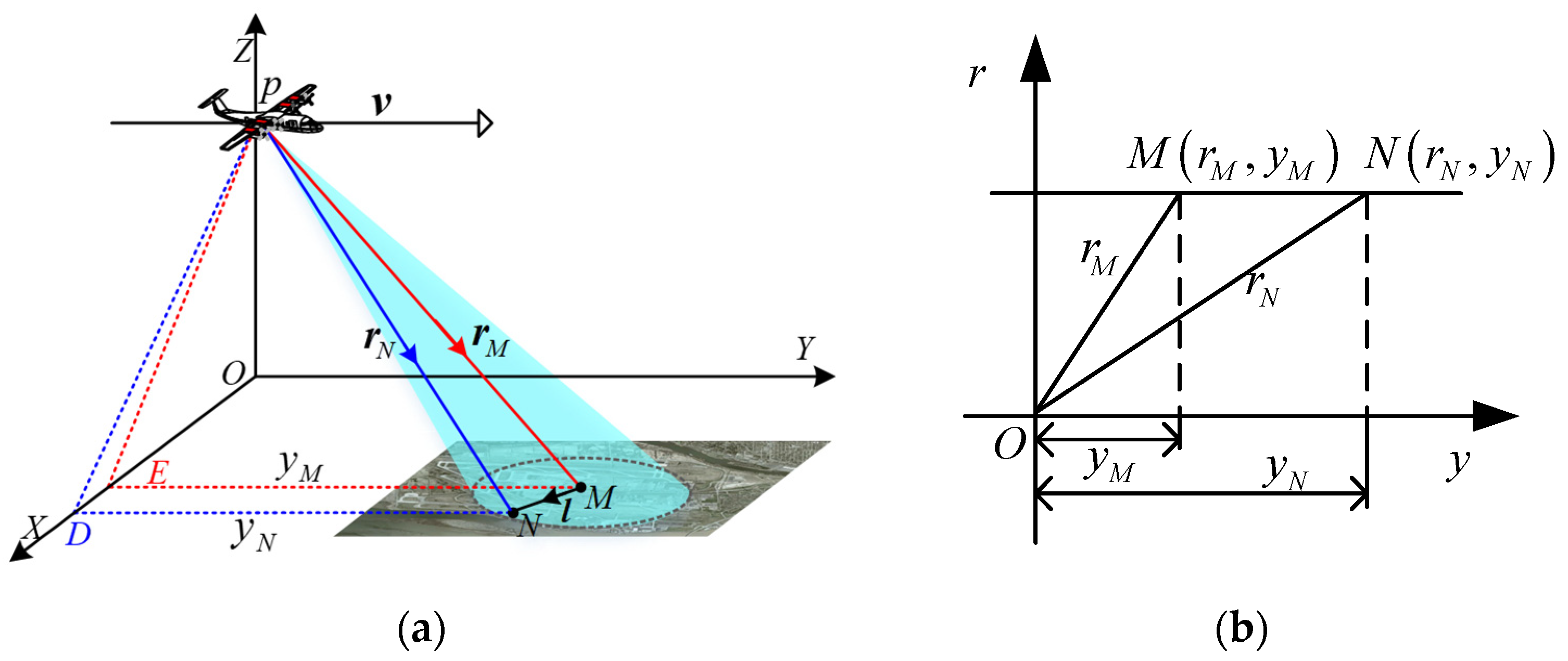
The squinted SAR imaging geometry is shown in Figure 1. The platform p travels along the Y-axis with velocity . Assuming that M is the central point and that N is an arbitrary point of the scene, then and are the slant ranges from p to M and N at the aperture center moment (ACM). The azimuth position of points M and N at ACM are and , and denotes the position vector from M to N.
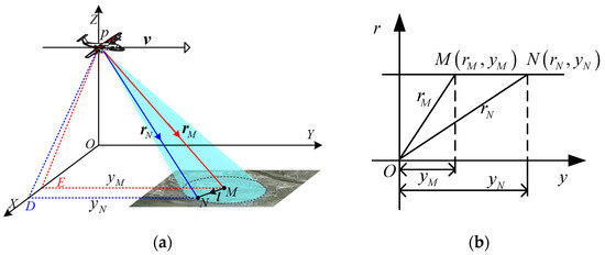
Figure 1.
Squinted SAR imaging geometry in (a) Cartesian and (b) Slant-range plane coordinates.
Based on the imaging geometry, the instantaneous range history of the arbitrary point N can be given as:
where is the slow time, denotes the norm operation, and is the instantaneous range history of point M.
In CPFA, the range history in (1) is first expanded into the first-order Taylor series as follows:
where denotes the inner product operator, is the unit vector of , and is the range error caused by (2). Suppose that the ground plane is a planar surface without topographic effects, i.e., . One condition for establishing (2) is that should be much smaller than . A CPFA image formed in the ground plane is much preferred, having smaller distortions and good phase-history matching [28], while in high-resolution highly squinted cases, the effects caused by wavefront bending would greatly deteriorate the image performance at the age of the scene. In addition, as shown in (2), the target height is ignored in CPFA. One alternative way to produce a SAR image from the received samples is to consider a set of coordinate axes in the slant plane by expanding the range history into slant- and cross-range components according to the forms of real data storage.
In order to extend the imaging scene and improve the imaging performance, a new range model based on 2-D Taylor series expansion is proposed. The corresponding to can be rewritten as:
Given that in (3) are described by and , the expression can be re-expanded as:
where , , and denotes the range error caused by wavefront curvature. The expanded coefficients and varying with the azimuth time can be given as:
2.2. Wavefront Curvature Error Analysis
The CPFA can achieve good imaging performance for small scenes. However, in high-resolution highly squinted images, the wavefront curvature error would cause severe defocusing effects and geometric distortion in large scene-size imaging. The wavefront curvature error cannot be ignored and must be analyzed. The curvature errors caused by the traditional range model and the proposed range model are given as, respectively:
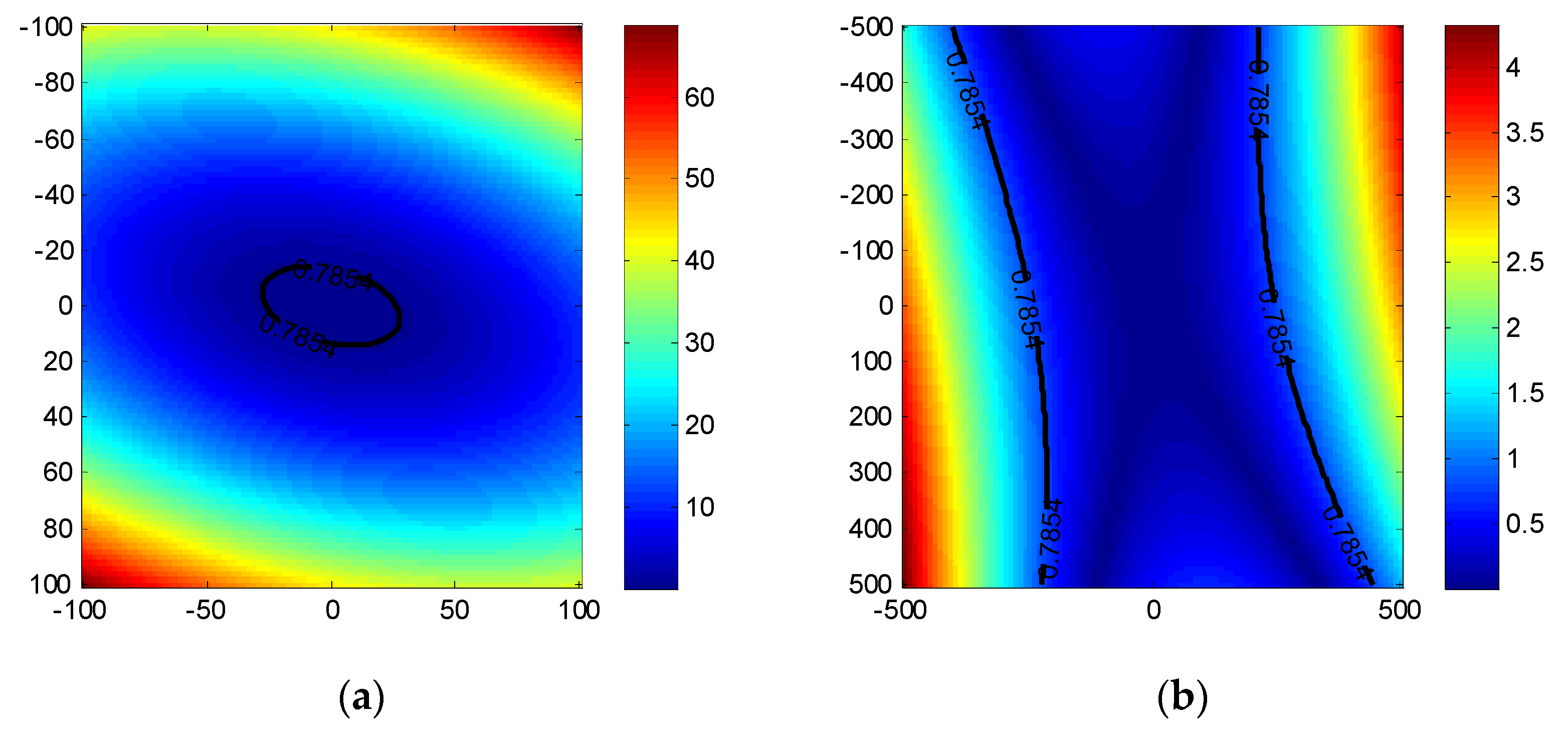
Applying the parameters listed in Table 1, the phase errors resulting from (6) are shown in Figure 2. The is considered the boundary. Note that the proposed range model is more appropriate for large scenes compared with the traditional. If the imaging scene becomes even larger, the focusing algorithm should consider the wavefront curvature error.

Table 1.
Parameter settings.
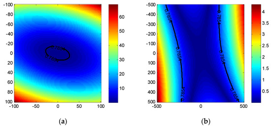
Figure 2.
Phase errors caused by wavefront curvature error. (a) CPFA; (b) EPFA.
The range error can be approximated as:
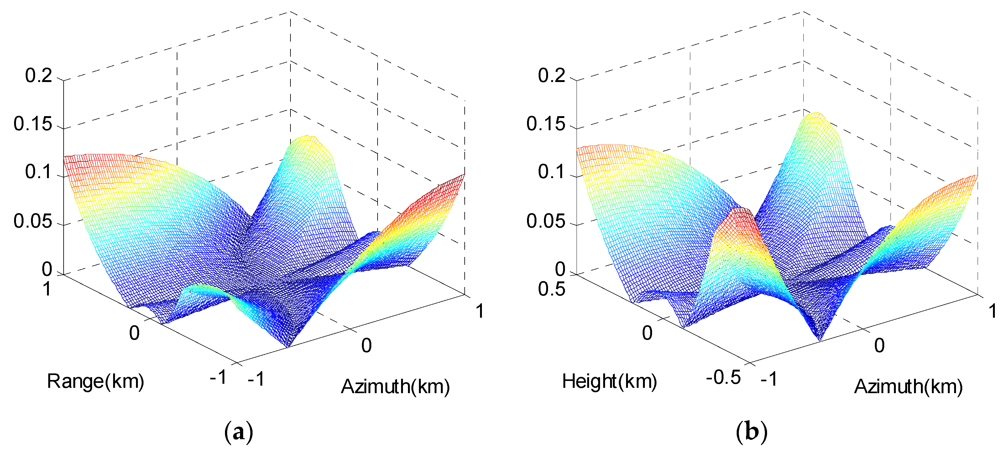
The phase errors caused by the 2-D Taylor series expansion of curvature range error are shown in Figure 3, and the unit of the contour map is . The maximum phase errors in the image scene are far less than , which indicates the accuracy of this third-order model is satisfactory.
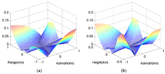
Figure 3.
Phase errors caused by the approximation of the curvature range error: (a) In range–azimuth plane; (b) in the height–azimuth plane.
3. Imaging Approach
The linear frequency modulation (LFM) signal is assumed to be the transmitted signal. We transform the signal to the range frequency domain and perform range compression. Then the echo signal is given by:
where and are the range frequency and azimuth time windows, and are the carrier and range frequencies, and represents the speed of light. Then, (3) can be expressed as:
where is the range wavenumber.
3.1. EPFA
Substituting (4) into (9), the phase of the echo signal after range compression can be expressed as:
The first term could be removed by the bulk compensation, and the compensation function can be constructed by the reference point M, i.e.,
After bulk compensation with (11), the reference point can be well-focused, whereas the others cannot. The interpolations are performed with a different mapping function from those of the CPFA, given by:
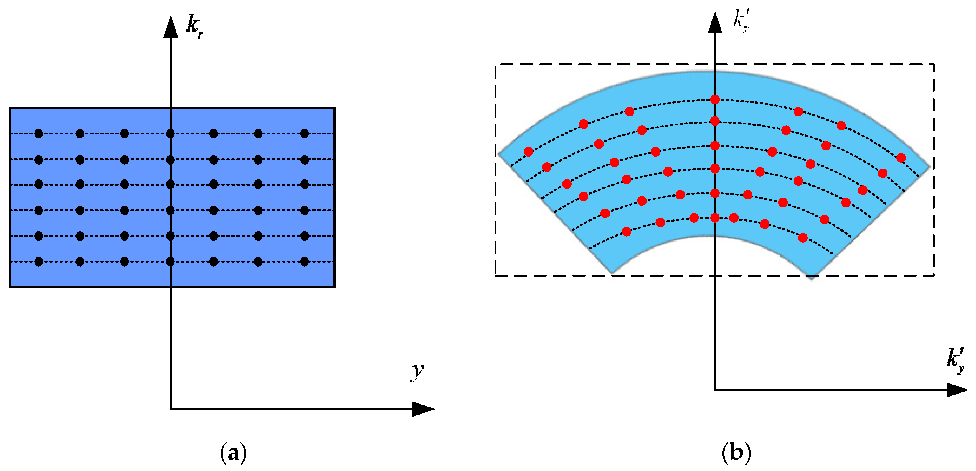
where and are both the new wavenumbers. Figure 4 depicts the raw data distribution variations, from to domains after the mapping of (12). Different from CPFA in the squinted SAR, a rectangle can be used to restrict the polar region of support and exploit all of the sampled data, eliminating the spatial variations without losing resolution. Additionally, the interpolation operations can be replaced using the NuFFTs to decrease the computational loads [36,37].
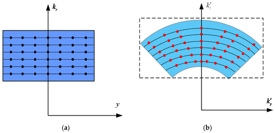
Figure 4.
Raw data distribution change diagram of EPFA. (a) Sampled data before mapping; (b) sampled data after mapping.
Via the 2-D interpolation processing, the signal changes from to the new coordinate domain ,
The first-order exponential term determines the target position in the imaging domain. The second exponential term is wavefront bending, whose form changes after the interpolation. Then, the range inverse Fourier transform (IFT) and azimuth FT are performed to (13), producing a focused image in the slant plane.
(14) represents the outcome of 2-D coarse focusing, and is the phase error in the imaging domain. In the CPFA, a 2-D IFT produces a focused image in the ground plane, ignoring the effects of the residual phase errors. Generally, the residual error introduced by the plane-wave assumption [33] limits the DOF greatly. The residual phase errors should be considered in the subsequent compensation.
3.2. Space Variance Phase Error Compensation
As analyzed in the previous section, the wavefront curvature range error can deteriorate the focusing performance for large scenes. After the EPFA processing, a space-variant filter is employed to eliminate the defocus effects induced by . Based on the EPFA, a space-variant error compensation method is adopted in this paper, which is a subblock compensation method.
3.2.1. Phase Compensation Filter
The space-variant phase error after interpolation can be expressed as in (13), which is obtained by the mapping relation provided by (10) from . Substituting (7) into (13), the residual phase after the 2-D interpolation is expressed as:
Using the 2-D interpolation processing in (12), the original azimuth time becomes the non-uniform sampling time . The new azimuth time can be deduced from (12), such that
Then, can be obtained as:
Note that is a function of and . Then, (15) can be rearranged as:
where the coefficient is space-variant and is given as:
Thus, the space-variant wavenumber domain filter can be expressed as:
3.2.2. Space-Variant Filter Implementation
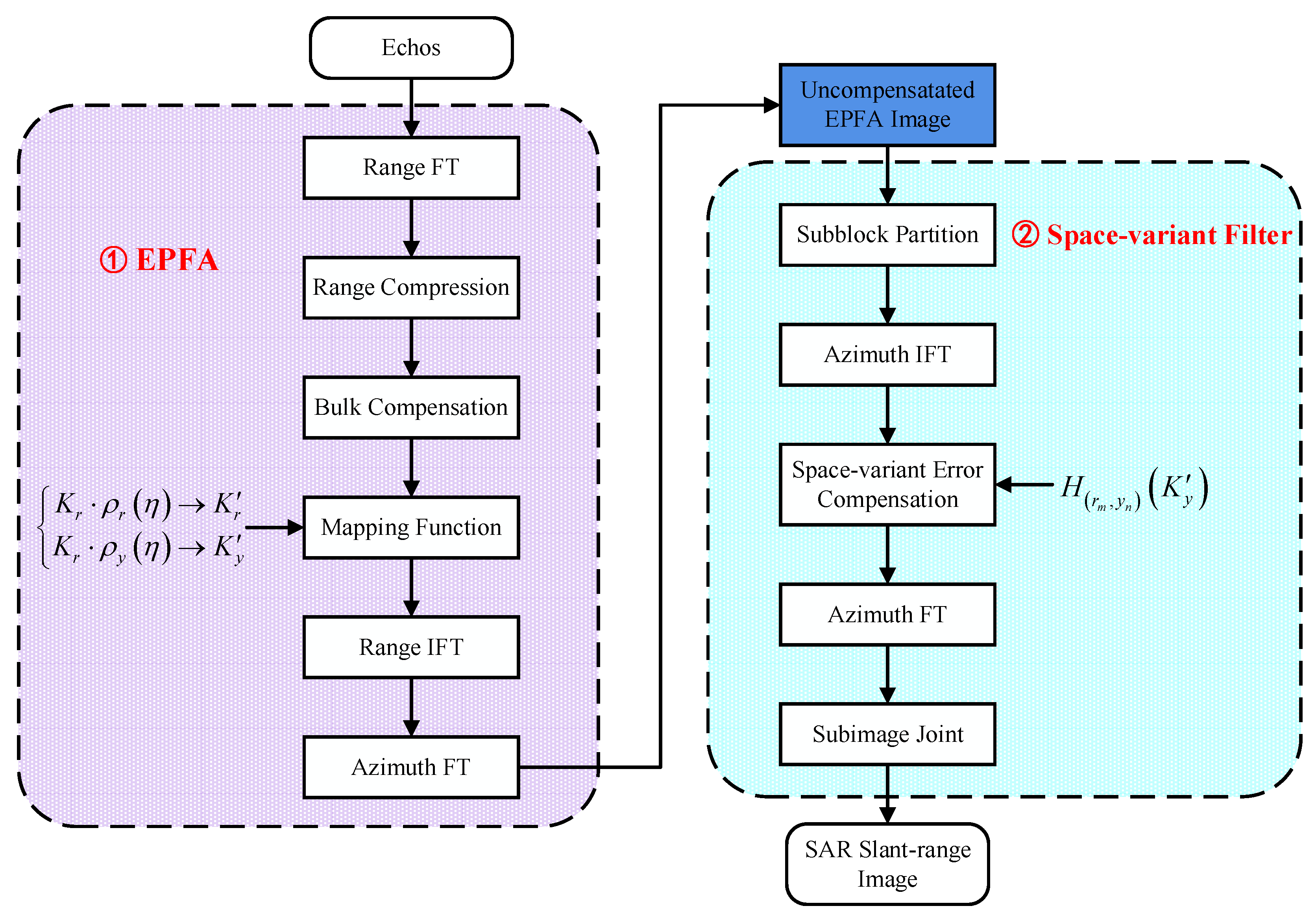
Since the coefficients are space-variant, the computation burden would be enormous if is varied with the target position according to the expression in (20). Processing can be made considerably more efficient by updating the filter function only as rapidly as required to maintain the residual defocus at an acceptable level [37]. Thus, the uncompensated EPFA image must be divided into several subblocks for curvature phase error correction. This method considers the phase error space-invariant in the subblock and the space-variant between subblocks. Then, the spectra of subblocks are multiplied by the compensation filter with the updated parameters corresponding to their central positions. The detailed implementation steps are shown below:
- (1)
- Partition: The uncompensated EPFA image is divided into sub-images, which should guarantee that at the edge of the sub-image, the residual defocus can be neglected after filter implementation. and represent the numbers of sub-images in the range and azimuth dimensions, respectively.
- (2)
- Filter: A sub-image of the interpolated echo signal in (14) is obtained by windowing, which has a size of and centers on the pixel grid . According to the pixel , the space-variant error compensation factor in the azimuth wavenumber domain can be constructed as follows:
- The subblock data are carried out using the azimuth IFT and multiplied by the . The space-variant error is then eliminated in the azimuth wavenumber domain. Finally, the azimuth FT is used to yield the compensated focused image.
- (3)
- Joint: The previous steps are repeated for all the sub-images. Then the whole image can be created by splicing all the compensated output images of the subregions.
The entire EPFA flowchart is presented in Figure 5. The EPFA is easy to implement, having simple process flows similar to the CPFA. The only difference between the CPFA and the EPFA is the mapping functions derived from various decompositions. In particular, the mapping functions could be performed using 2-D interpolation. However, in terms of the computational burden, two one-dimensions (1-Ds) [32,33] and NuFFTs [36] are the preferred option. In addition, the EPFA accounts for the space-variant phase error and extends the imaging scene. The filter processing is realized by compensating for the phase error of the central pixel of the sub-image by providing approximate corrections to the surrounding points, thereby reducing computations and ensuring image continuity.
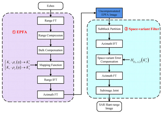
Figure 5.
Flowchart of the EPFA.
3.3. Computation Analyses
As shown in Figure 5, the EPFA primarily contains two range FT/IFT operations, one azimuth FT/IFT operation, two complex multiplications, and one 2-D interpolation. The computational loads of EPFA with specific formulas are derived as:
where N and M are the range and azimuth sampling numbers, respectively, and k is the kernel length of the 2-D interpolation. The phase compensation filter process contains two azimuth FT/IFT operations and one complex multiplication. If the uncompensated image is divided into sub-images, the total computational load of the focusing method for the nonparallel sequential execution is:
where and are the sampling number in the range and azimuth direction of each sub-image, respectively. The BPA [24] is then used for comparison.
To analyze the time complexity conveniently, we assume that the number of azimuth and range sampling numbers are M and that the number of image pixels is . In the proposed algorithm, the order of magnitude of time complexity is , similar to the CPFA, whereas the BPA is . As a result, the order of magnitude of time complexity of the EPFA is less than that of the BPA but is equal to that of the CPFA.
4. Simulation Results
Simulated and real image datasets were used in experiments to evaluate the performance and effectiveness of the proposed approach.
4.1. Simulated Data Analyses
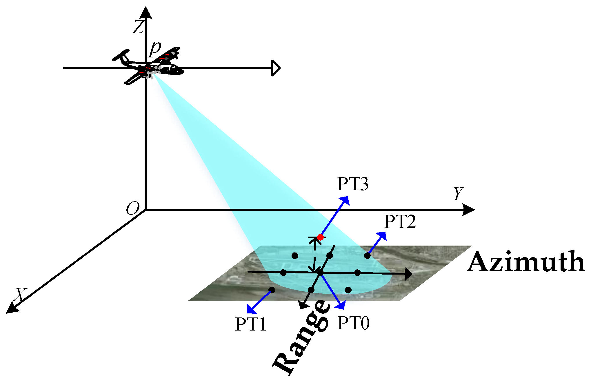
Simulated data were used to verify the effectiveness of the proposed approach. A 3 × 3 dot matrix was set in the simulated scene, with central target PT0 as the reference target. A point target PT3, indicated by the red dot, is at a 0.2 km altitude, with the same coordinates in the horizontal plane as PT0. The scene geometry is displayed in Figure 6, with a scene size of 2 km × 2 km, and Table 1 summarizes the simulation parameters.
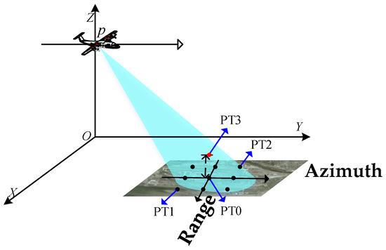
Figure 6.
The simulated scene for highly squinted SAR.
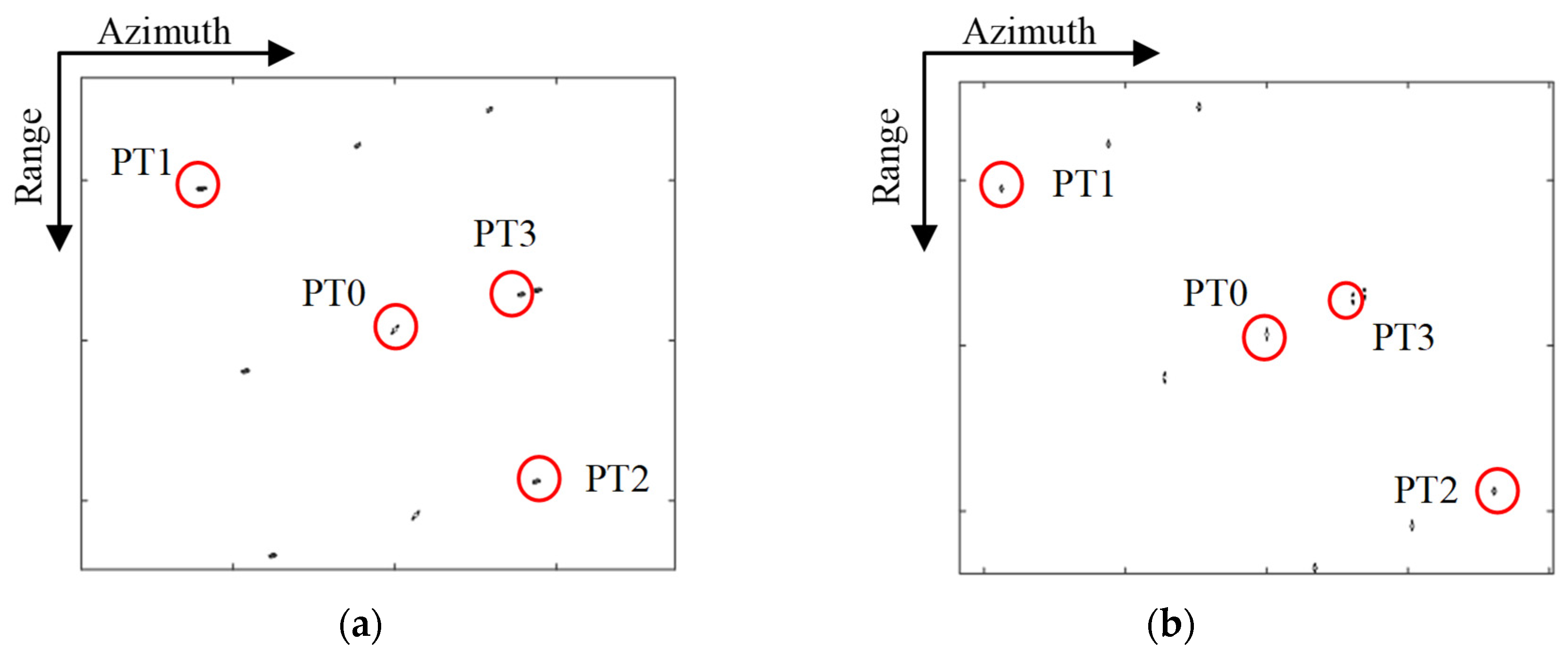
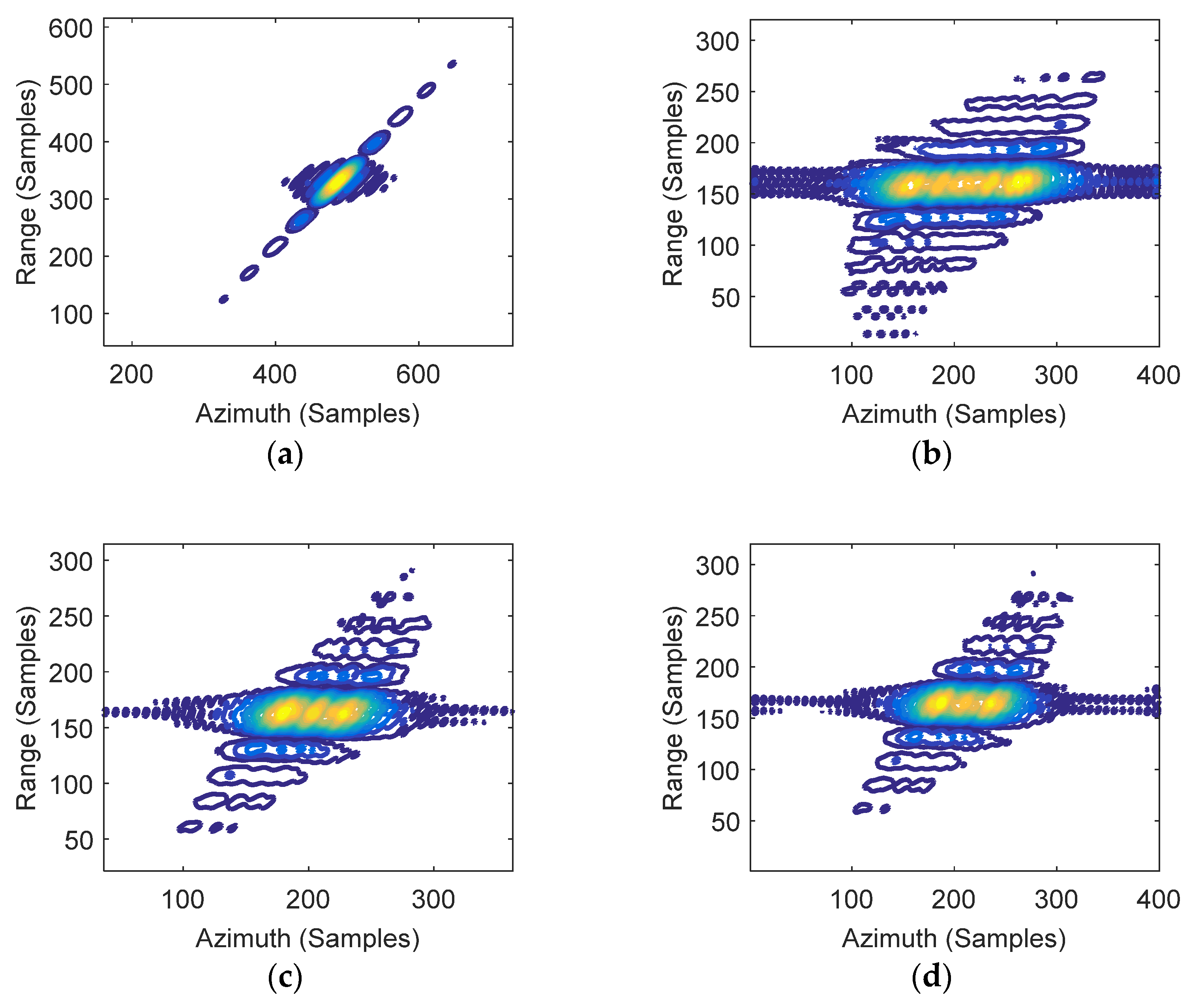
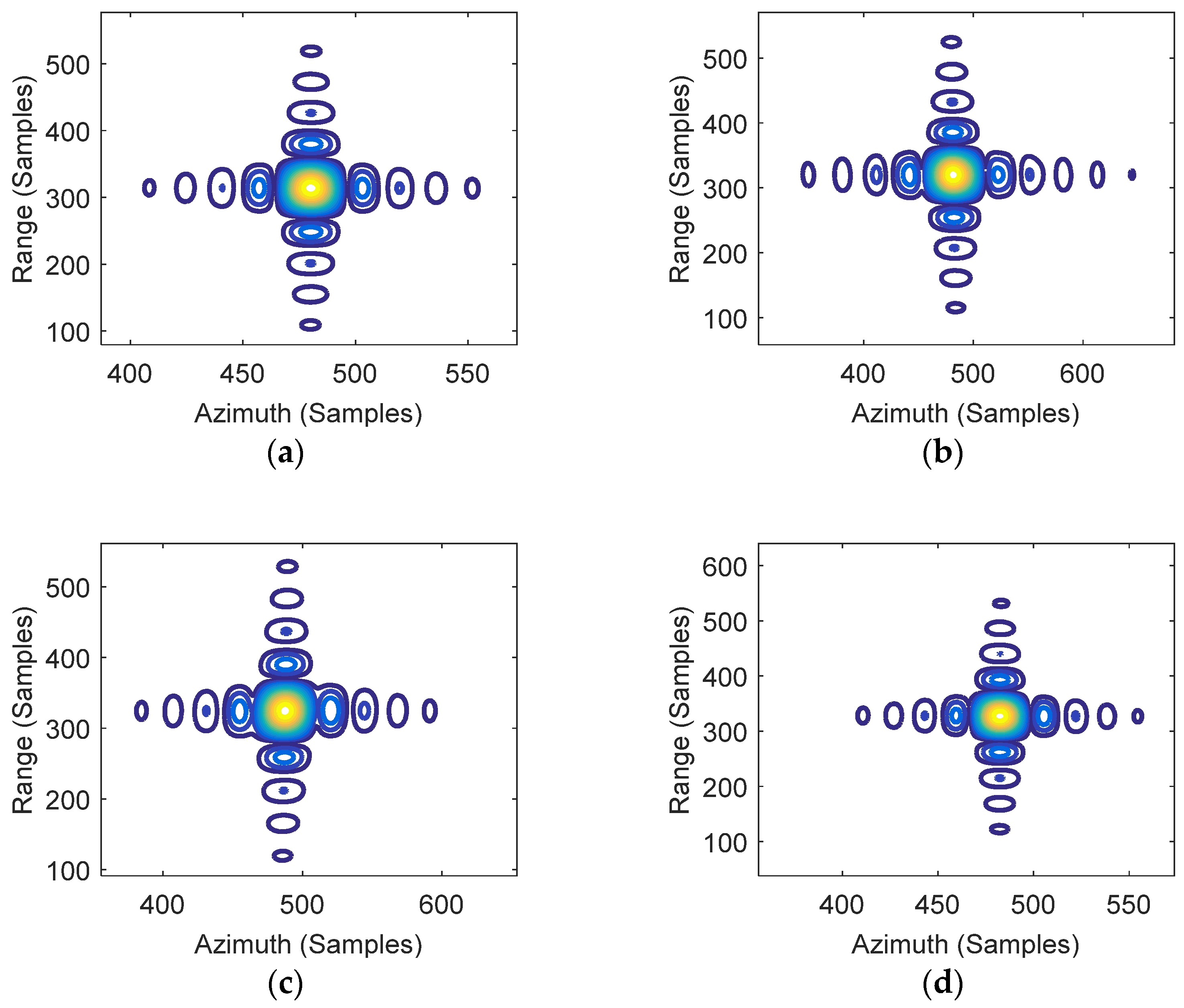
Figure 7 presents the image results for the entire target area using the CPFA and EPFA. The focusing results for point targets PT0, PT1, PT2, and PT3 are marked by red circles. To further assess the performance of the proposed algorithm, a comparative analysis was then carried out. The contour plots for the impulse response function (IRF) of the four targets are shown in Figure 8 and Figure 9.
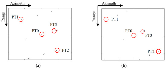
Figure 7.
Imaging result of the whole scene. (a) CPFA; (b) EPFA.
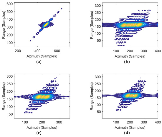
Figure 8.
2-D IRF of targets by CPFA. (a) PT0; (b) PT1; (c) PT2; (d) PT3.
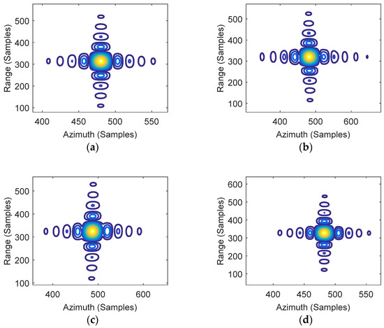
Figure 9.
2-D IRF of targets by EPFA. (a) PT0; (b) PT1; (c) PT2; (d) PT3.
The contour plots in Figure 7a were refined and are presented in Figure 8. Note that the center point target PT0 is well-focused, while the edge targets PT1 and PT2 are seriously defocused due to large residual phase errors. The 2-D impulse response functions (IRFs) of targets circled in Figure 7b are shown in Figure 9. The imaging results by EPFA are visually well-focused in both the range and azimuth dimensions for the central target and the edge targets PT1 and PT2.
The comparative results for PT3 by CPFA and EPFA are given in Figure 8d and Figure 9d. Note that the imaging result of the EPFA (Figure 9d) can be well-focused, while the CPFA result greatly deteriorated due to the out-of-plane projection. This indicates that the focusing results of the proposed approach will not be affected by height variation, whereas the focusing results of the traditional method are defocused as a result of ignoring the height variation. It is important to point out that the position of the elevated target is still inaccurate in the EPFA since the target is projected into the slant plane with the incorrect position (layover phenomena) [20,21]. The geometric distortion brought by topography variations should be corrected as discussed in [16,17].
To evaluate the performance of the proposed approach, the imaging quality parameters, i.e., the impulse response width (IRW), peak sidelobe ratio (PSLR), and integration sidelobe ratio (ISLR), are calculated and analyzed. The summary of the results is listed in Table 2, which demonstrates the superiority of the proposed method.

Table 2.
Image quality parameters.
4.2. Real Data Experiments
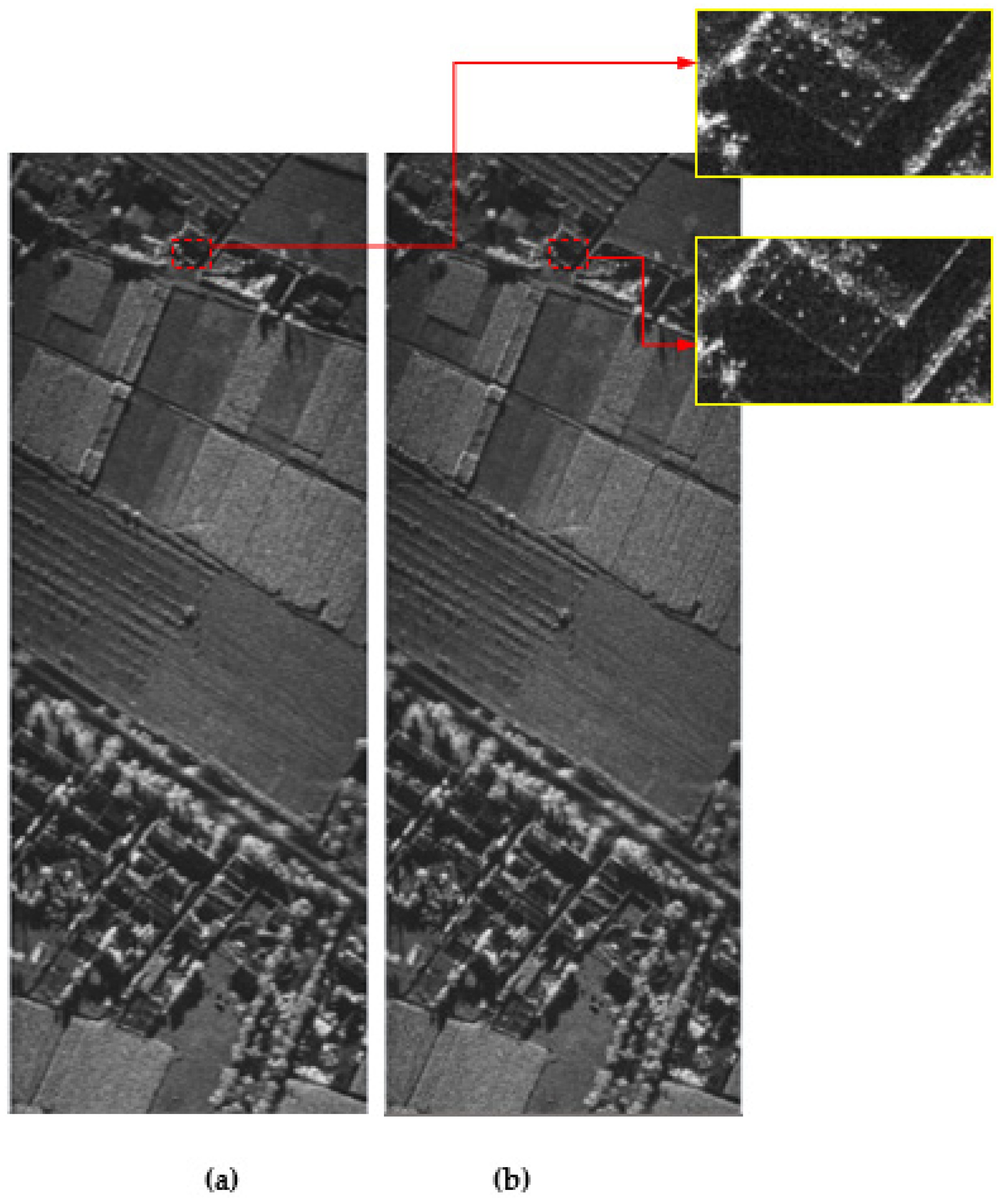
Real data from an experimental X-band SAR were processed using the EPFA and CPFA for comparative analysis. The platform speed was 32 m/s, the trajectory height was approximately 1500 m, the squint angle was 49°, the transmitted signal bandwidth was 800 MHz, and the azimuth resolution was 0.3 m. Figure 10 shows the experimental results for the CPFA and EPFA.
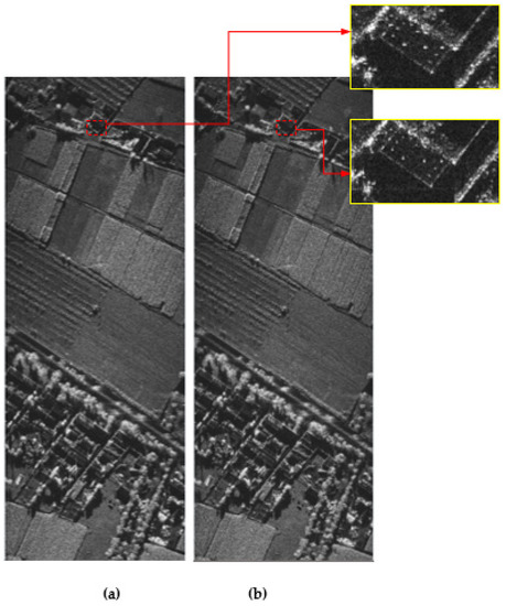
Figure 10.
Experimental results. (a) CPFA; (b) EPFA.
In order to facilitate comparison, Figure 10b shows the focused result on the ground plane projected by the slant-plane image. The Hamming windows were also added in both cases. The results show that the processed image of the EPFA is comparatively better focused than the CPFA, particularly in the reflector area (see highlighted regions). Image entropy is used to quantitatively evaluate the imaging results of the real data in this paper. For SAR images, it is generally believed that the smaller the image entropy, the better the image focus [46]. In this experiment, the image entropy values, i.e., 2.66 and 2.37 corresponding to CPFA and EPFA, respectively, are computed to show the superiority of the proposed approach. The experimental results suggest that the proposed EPFA provides better focusing effects for HRHS SAR data than the conventional approach.
5. Conclusions
Spatially variant distortions and defocusing effects caused by the wavefront curvature assumption in the CPFA become more pronounced in large scene images. To address this problem, the EPFA was developed for HRHS SAR images, adopting a new range model based on the 2-D Taylor series expansion and accounting for the wavefront curvature error. The 2-D interpolation function is derived in the slant-range plane, and the compensation filter is designed for the space-variant phase errors. In contrast to the CPFA performed in the ground plane, the EPFA is developed using a slant range and an azimuth position in the slant-range plane. The proposed approach has a much larger DOF than the CPFA because of the slant-range decomposition and space-variant correction procedures; the EPFA’s performance is also unaffected by the target height. The experimental results using simulated and real image data show that the proposed method performed well, achieving better focusing effects than the CPFA. However, it is noted that the focusing results presented in this paper did not consider geometric correction. Subsequent studies should focus on developing the geometric correction method for the EPFA to improve the performance and applicability of the proposed algorithm.
Author Contributions
P.G. conceived the main idea; F.W. and P.G. conceived and designed the experiments; A.W. analyzed the data; P.G. and F.W. wrote the paper. All authors have read and agreed to the published version of the manuscript.
Funding
This work was supported in part by the National Natural Science Foundation of China under Grants 61701393, and 61971329, in part by Natural Science Basis Research Plan in Shaanxi Province of China under Grant 2020ZDLGY02-08, and in part by Funded by National Key Laboratory of Science and Technology on Space Microwave, No. HTKJ2022KL504019.
Conflicts of Interest
The authors declare no conflict of interest.
References
- An, D.; Huang, X.; Jin, T.; Zhou, Z. Extended nonlinear chirp scaling algorithm for high-resolution highly squint SAR data focusing. IEEE Trans. Geosci. Remote Sens. 2012, 50, 3595–3609. [Google Scholar] [CrossRef]
- Xu, G.; Zhang, B.; Chen, J.; Hong, W. Structured Low-rank and Sparse Method for ISAR Imaging with 2D Compressive Sampling. IEEE Trans. Geosci. Remote Sens. 2022, in press.
- Xu, G.; Zhang, B.; Yu, H.; Chen, J.; Xing, M.; Hong, W. Sparse Synthetic Aperture Radar Imaging from Compressed Sensing and Machine Learning: Theories, Applications and Trends. IEEE Trans. Geosci. Remote Sens. 2022, in press.
- Xing, M.; Wu, Y.; Zhang, Y.D.; Sun, G.; Bao, Z. Azimuth resampling processing for highly squinted synthetic aperture radar imaging with several modes. IEEE Trans. Geosci. Remote Sens. 2014, 52, 4339–4352. [Google Scholar] [CrossRef]
- Zhang, S.; Xing, M.; Xia, L.; Zhang, L.; Guo, R.; Bao, Z. Focus improvement of high-squint SAR based on azimuth dependence of quadratic range cell migration correction. IEEE Geosci. Remote Sens. Lett. 2013, 10, 150–154. [Google Scholar] [CrossRef]
- Jin, M.Y.; Wu, C. A SAR correlation algorithm which accommodates large range migration. IEEE Trans. Geosci. Remote Sens. 1984, GRS-22, 592–597. [Google Scholar] [CrossRef]
- Curlander, J.C.; McDonough, R.N. Synthetic Aperture Radar: Systems and Signal Processing; Wiley: Hoboken, NJ, USA, 1991. [Google Scholar]
- Bamler, R. A comparison of range-Doppler and wavenumber domain SAR focusing algorithms. IEEE Trans. Geosci. Remote Sens. 1992, 30, 706–713. [Google Scholar] [CrossRef]
- Raney, R.K.; Runge, H.; Cumming, I.G.; Bamler, R.; Wong, F.H. Precision of SAR processing using chirp scaling. IEEE Trans. 1994, 32, 786. [Google Scholar] [CrossRef]
- Davidson, G.W.; Cumming, I.G. Signal properties of spaceborne squint-mode SAR. IEEE Trans. Geosci. Remote Sens. 1997, 35, 611–617. [Google Scholar] [CrossRef]
- Davidson, G.W.; Cumming, I.G.; Ito, M.R. A chirp scaling approach for processing squint mode SAR data. IEEE Trans. Aerosp. Electron. Syst. 1996, 32, 121–133. [Google Scholar] [CrossRef]
- Moreira, A.; Huang, Y. Airborne SAR processing of highly squinted data using a chirp scaling approach with integrated motion compensation. IEEE Trans. Geosci. Remote Sens. 1994, 32, 1029–1040. [Google Scholar] [CrossRef]
- Moreira, A.; Mittermayer, J.; Scheiber, R. Extended chirp scaling algorithm for air- and spaceborne SAR data processing in stripmap and ScanSAR imaging modes. IEEE Trans. Geosci. Remote Sens. 1996, 34, 1123–1136. [Google Scholar] [CrossRef]
- Wong, F.H.; Yeo, T.S. New applications of nonlinear chirp scaling in SAR data processing. IEEE Trans. Geosci. Remote Sens. 2001, 39, 946–953. [Google Scholar] [CrossRef]
- Yeo, T.S.; Tan, N.L.; Zhang, C.B.; Lu, Y.H. A new subaperture approach to high squint SAR processing. IEEE Trans. Geosci. Remote Sens. 2001, 39, 954–968. [Google Scholar]
- Zhu, D.Y.; Shen, M.W.; Zhu, Z.D. Some aspects of improving the frequency scaling algorithm for dechirped SAR data processing. IEEE Trans. Geosci. Remote Sens. 2008, 46, 1579–1588. [Google Scholar]
- Sun, G.; Xing, M.; Liu, Y.; Sun, L.; Bao, Z.; Wu, Y. Extended NCS Based on Method of Series Reversion for Imaging of Highly Squinted SAR. IEEE Geosci. Remote Sens. Lett. 2011, 8, 446–450. [Google Scholar] [CrossRef]
- Sun, G.; Jiang, X.; Xing, M.; Qiao, Z.; Wu, Y.; Bao, Z. Focus Improvement of Highly Squinted Data Based on Azimuth Nonlinear Scaling. IEEE Trans. Geosci. Remote Sens. 2011, 49, 2308–2322. [Google Scholar] [CrossRef]
- Li, Z.Y.; Liang, Y.; Xing, M.; Zheng, B. New subaperture imaging algorithm and geometric correction method for high squint diving SAR based on equivalent squint model. J. Electron. Inf. Technol. 2015, 37, 1814–1820. [Google Scholar]
- Chen, J.; Kuang, H.; Yang, W.; Liu, W.; Wang, P. A novel imaging algorithm for focusing high-resolution spaceborne SAR data in squinted sliding-spotlight mode. IEEE Geosci. Remote Sens. Lett. 2016, 13, 1577–1581. [Google Scholar] [CrossRef]
- Zeng, L.; Liang, Y.; Xing, M.; Huai, Y.; Li, Z. A novel motion compensation approach for airborne spotlight SAR of high-resolution and high-squint mode. IEEE Geosci. Remote Sens. Lett. 2016, 13, 429–433. [Google Scholar] [CrossRef]
- Wang, Y.; Li, J.; Xu, F.; Yang, J. A New Nonlinear Chirp Scaling Algorithm for High-Squint High-Resolution SAR Imaging. IEEE Geosci. Remote Sens. Lett. 2017, 14, 2225–2229. [Google Scholar] [CrossRef]
- Zhong, H.; Zhang, Y.; Chang, Y.; Liu, E.; Tang, X.; Zhang, J. Focus high-resolution highly squint SAR data using azimuth-variant residual RCMC and extended nonlinear chirp scaling based on a new circle model. IEEE Geosci. Remote Sens. Lett. 2018, 15, 547–551. [Google Scholar] [CrossRef]
- Munson, D.C.; Brien, J.O.; Jenkins, W.K. A tomographic formulation of spotlight-mode synthetic aperture radar. Proc. IEEE 1983, 71, 917–925. [Google Scholar] [CrossRef]
- Ulander, L.M.H.; Hellsten, H.; Stenstrom, G. Synthetic-aperture radar processing using fast factorized back-projection. IEEE Trans. Aerosp. Electron. Syst. 2003, 39, 760–776. [Google Scholar] [CrossRef]
- Zhang, L.; Li, H.-L.; Qiao, Z.-J.; Xu, Z.-W. A fast BP algorithm with wavenumber spectrum fusion for high-resolution spotlight SAR imaging. IEEE Geosci. Remote Sens. Lett. 2014, 11, 1460–1464. [Google Scholar] [CrossRef]
- Li, Z.; Xing, M.; Liang, Y.; Gao, Y.; Chen, J.; Huai, Y.; Zeng, L.; Sun, G.; Bao, Z. A Frequency-Domain Imaging Algorithm for Highly Squinted SAR Mounted on Maneuvering Platforms with Nonlinear Trajectory. IEEE Trans. Geosci. Remote Sens. 2016, 54, 4023–4038. [Google Scholar] [CrossRef]
- Tang, S.; Zhang, L.; Guo, P.; Zhao, Y. An omega-K algorithm for highly squinted missile-borne SAR with constant acceleration. IEEE Geosci. Remote Sens. Lett. 2014, 11, 1569–1573. [Google Scholar] [CrossRef]
- Yang, J.; Sun, G.; Xing, M.; Xia, X.-G.; Liang, Y.; Bao, Z. Squinted TOPS SAR imaging based on modified range migration algorithm and spectral analysis. IEEE Geosci. Remote Sens. Lett. 2014, 11, 1707–1711. [Google Scholar] [CrossRef]
- Li, Z.; Xing, M.; Xing, W.; Liang, Y.; Gao, Y.; Dai, B.; Hu, L.; Bao, Z. A Modified Equivalent Range Model and Wavenumber-Domain Imaging Approach for High-Resolution-High-Squint SAR With Curved Trajectory. IEEE Trans. Geosci. Remote Sens. 2017, 55, 3721–3734. [Google Scholar] [CrossRef]
- Walker, J.L. Range-Doppler imaging of rotating objects. IEEE Trans. Aerosp. Electron. Syst. 1980, AES-16, 23–51. [Google Scholar] [CrossRef]
- Tang, Y.; Xing, M.; Bao, Z. The polar format imaging algorithm based on double Chirp-Z transforms. IEEE Geosci. Remote Sens. Lett. 2008, 5, 610–614. [Google Scholar] [CrossRef]
- Wang, Y.; Li, J.; Chen, J.; Xu, H.; Sun, B. A parameter-adjusting polar format algorithm for extremely high squint SAR imaging. IEEE Trans. Geosci. Remote Sens. 2014, 52, 640–650. [Google Scholar] [CrossRef]
- Chen, J.; An, D.; Wang, W.; Luo, Y.; Chen, L.; Zhou, Z. Extended polar format algorithm for large-scene high-resolution WAS-SAR imaging. IEEE J. Sel. Topics Appl. Earth Observ. Remote Sens. 2021, 14, 5326–5338. [Google Scholar] [CrossRef]
- Tang, S.; Deng, H.; Guo, P.; Li, Y.; Zhang, L. Generalzied PFA for air-missile borne bistatic forward-looking beam-steering SAR with accelerations. IEEE Access 2019, 1, 74616–74627. [Google Scholar]
- Gorham, L.A.; Rigling, B.D. Scene size limits for polar format algorithm. IEEE Trans. Aerosp. Electron. Syst. 2016, 52, 73–84. [Google Scholar] [CrossRef]
- Doren, N.E.; Jakowatz, C.V.; Wahl, D.E.; Thompson, P.A. General Formulation for Wavefront Curvature Correction in Polar-Formatted Spotlight-Mode SAR Images Using Space-Variant Post –Filtering. In Proceedings of the International Conference on Image Processing, Santa Barbara, CA, USA, 26–29 October 1997; pp. 861–864. [Google Scholar]
- Wang, X.; Zhu, D.; Mao, X.; Zhu, Z. Space-variant filtering for wavefront curvature correction in polar formatted bistatic SAR image. IEEE Trans. Aerosp. Electron. Syst. 2012, 48, 940–950. [Google Scholar] [CrossRef]
- Hu, R.; Li, X.; Yeo, T.S.; Yang, Y.; Chi, C.; Zuo, F.; Hu, X.; Pi, Y. Refocusing and zoom-in polar format algorithm for curvilinear spotlight SAR imaging on arbitrary region of interest. IEEE Trans. Geosci. Remote Sens. 2019, 57, 7995–8010. [Google Scholar] [CrossRef]
- Hu, R.; Rao, B.S.M.R.; Alaee-Kerahroodi, M.; Ottersten, B. Orthorectified polar format algorithm for generalized spotlight SAR imaging with DEM. IEEE Trans. Geosci. Remote Sens. 2021, 59, 3999–4007. [Google Scholar] [CrossRef]
- Mao, X.; Zhu, D.; Zhu, Z. Polar Format Algorithm Wavefront Curvature Compensation Under Arbitrary Radar Flight Path. In Proceedings of the 2011 IEEE CIE International Conference on Radar, Chengdu, China, 24–27 October 2011; pp. 1382–1385. [Google Scholar]
- Nie, X.; Lei, W.; Zhuang, L. A Two-Step Wide-Scene Polar Format Algorithm for High-Resolution Highly squinted SAR. IEEE Geosci. Remote Sens. Lett. 2022, 19, 1–5. [Google Scholar] [CrossRef]
- Deng, H.; Li, Y.; Liu, M.; Mei, H.; Quan, Y. A space-variant phase filtering imaging algorithm for missile-borne BiSAR with arbitrary configuration and curved track. IEEE Sensor J. 2018, 18, 3311–3326. [Google Scholar] [CrossRef]
- Miao, Y.; Wu, J.; Li, Z.; Yang, J. A Generalized Wavefront-Curvature-Corrected Polar Format Algorithm to Focus Bistatic SAR Under Complicated Flight Paths. IEEE J. Sel. Topics Appl. Earth Observ. Remote Sens. 2020, 13, 3757–3771. [Google Scholar] [CrossRef]
- Jokowartz, C.V.; Wahl, D.E.; Eichel, P.H.; Ghiglia, D.C.; Thompson, P.A. Spotlight-Mode Synthetic Aperture Radar: A Signal Processing Approach; Kluwer: Norwell, MA, USA, 1996. [Google Scholar]
- Li, X.; Liu, G.; Ni, J. Autofocusing of ISAR images based on entropy minimization. IEEE Trans. Aerosp. Electron. Syst. 1999, 35, 1240–1252. [Google Scholar] [CrossRef]
Disclaimer/Publisher’s Note: The statements, opinions and data contained in all publications are solely those of the individual author(s) and contributor(s) and not of MDPI and/or the editor(s). MDPI and/or the editor(s) disclaim responsibility for any injury to people or property resulting from any ideas, methods, instructions or products referred to in the content. |
© 2023 by the authors. Licensee MDPI, Basel, Switzerland. This article is an open access article distributed under the terms and conditions of the Creative Commons Attribution (CC BY) license (https://creativecommons.org/licenses/by/4.0/).

