Article

Multi-Temporal PSI Analysis and Burn Severity Combination to Determine Ground-Burned Hazard Zones

by
Vasilis Letsios
1,*,
Ioannis Faraslis
2 and
Demetris Stathakis
1
1
Spatial Analysis, GIS and Thematic Mapping Laboratory, Department of Planning and Regional Development, University of Thessaly, 38334 Volos, Greece
2
Department of Environmental Sciences, University of Thessaly, 41222 Larisa, Greece
*
Author to whom correspondence should be addressed.
Remote Sens. 2023, 15(18), 4598; https://doi.org/10.3390/rs15184598
Submission received: 12 July 2023 / Revised: 23 August 2023 / Accepted: 15 September 2023 / Published: 19 September 2023

Abstract

:
Forest fires are a seasonal phenomenon in Greece, reoccurring annually and causing adverse impacts on both human-made and natural environments. Our case study focuses on the devastating fire that took place in July 2018 in the second-housing area of Mati, East Attica. In this research, we propose a simple and effective approach that combines the deformation trend obtained from the Permanent Scatterer Interferometry (PSI) analysis with the burn severity assessment aiming to identify and classify potential ground-burn hazard zones. To maximize the number of measuring points, we employ a weighted full-graph PSI approach. Additionally, we calculate the burn severity by comparing Sentinel-2 satellite images captured before and after the event. The resulting datasets are reclassified on a scale from 1 to 5, and the proposed equation yields the final product. Numerous high and very high hazard zones have been identified using this methodology. The research findings reveal the proximity between these hazard zones and the stream network. Overall, the proposed method offers valuable insights for the post-fire monitoring and management of urban and peri-urban landscapes in the affected areas.

1. Introduction

Natural disasters such as forest fires are seasonal phenomena in Greece occurring every year and emerging as a highly controversial topic in terms of post-catastrophic management. A broad statistical view of fires in Greece is provided by the European Forest Fire Information System (EFFIS) (https://effis.jrc.ec.europa.eu/, accessed on) as shown in Figure 1.
Such occurrences exert high pressure on urban and peri-urban landscapes, making urban planning a challenging task. Furthermore, urban sprawl, a negative form of urban expansion [1] and a chronic problem in Greece, adds a greater degree of difficulty to the planning and management of the affected areas. Such an example is the broader area of Mati on the east coast of the Attica region, 30 km east of Athens. In July 2018, a wildfire that evolved into a deadly urban conflagration engulfed the area resulting into an unprecedented toll on human life and substantial damage to the buildings, infrastructure, and the natural environment. Remarkably, it is characterized as one of the most devastating fires of the century, globally. The disaster is partially attributed to inefficient urban planning with an ill-structured street layout along with illegal and unplanned constructions. Since then, intense ground deformation phenomena are observed, especially during severe rainstorms, posing a risk to the existing buildings and infrastructures. This statement is validated by the facts, as shown in Figure 2.
In early September 2022, a significant subsidence event impacted a residential building in the Neos Voutzas settlement. According to the official data from the Hellenic National Meteorological Service (http://www.emy.gr, accessed on 3 August 2023), the precipitation in January 2022 reached 91.2 mm, spanning across 25 rainy days. The region was densely vegetated prior to the fire, and the affected building is situated in alignment with the edges of a stream.
It is well known that the potential for severe soil erosion increases in a post-fire event since plant material is totally destroyed leading to soil stability degradation and connecting with major post-fire effects such as landslides, deformation, and soil changes [2,3]. The post-fire soil erosion has notably intensified across the extensive Mati settlement area, resulting in the onset of deformation phenomena. The escalation of soil loss subsequent to the fire event has been verified [4]. Despite the lack of official data linking soil changes during the pre-fire and post-fire periods, we operate under the assumption that this factor directly contributes to the occurrence of deformation phenomena.
This research aims to estimate the deformation trend in time, to map potential hazard zones, and to provide a valuable information layer regarding the preservation of the current urban landscape and a potential urban expansion in the future. A new special urban plan is now under consultation aiming towards urban regeneration, environmental protection, and dealing with the consequences of the catastrophic fire. Furthermore, we proposed a combination of the deformation trend and burn severity to classify the level of the hazard zones. Our research constitutes the first study using the Permanent Scatterers Interferometry (PSI) technique for this affected area and the combination with burn severity.
PSI is a powerful remote sensing tool established in the early 2000s and has the capability to estimate deformation and height over stable points that behave as permanent scatterers (PS) in time with high accuracy by exploiting large time series of radar images [5].
The original PSI technique is characterized by the restriction that a target must be coherent in all generated interferograms. This condition is easily met in urban areas where existing man-made structures are the dominant scatterers. To overcome this restriction and make PSI exploitation more feasible in different types of landscapes (rural, mountainous areas, vegetated, extra-urban, mixed-areas), several approaches are introduced with respect to the original PSI technique. The Small Baseline Subset (SBAS) technique is the first major extension using a small baseline image graph connection to minimize spatial decorrelation and the spatial coherence factor as a criterion for the points’ selection [6]. The Stanford Method for PS (StaMPS) [7] was introduced using a single-master baseline configuration and it is based on phase stability. A StaMPS method update [8] was introduced that combines the PS and SBAS methods. The Quasi-PS (QPS) approach [9] was introduced to deal with partially coherent targets. The method uses a minimum spanning tree (MST) image graph by maximizing the average spatial coherence and adopts the spatial coherence as the interferometric phase weight. The novel SqueeSAR algorithm was introduced [10] that uses a full-graph image connection and adopts the statistical homogeneity of neighboring pixels to jointly process the permanent (PS) and distributed (DS) scatterers. A more detailed review of PSI algorithms can be found in [11].
The contribution and validation of the PSI technique are well-established through several studies in the literature [12,13,14,15] related to various disciplines. Urban areas [16,17,18,19,20], infrastructure [21,22,23,24], groundwater [25,26,27,28], mining [29,30,31], geohazards [32,33,34,35,36], volcanos [37,38,39,40,41], oil, and gas [42,43,44] are some of the fields utilizing the PSI technique.
In this paper, our method focuses on the use of a multi-master approach adapting a full-graph connection with the use of spatial coherence as a weight to deal with the partially coherent targets, aiming to maximize the measuring points (PS and DS) in the study area. Due to the time-consuming processing of the weighted full-graph approach, we chose connected interferograms based on a coherence threshold value of 0.35, aiming to minimize the time processing and to guarantee that the graph remained connected, a mandatory factor for the proper implementation of the PSI technique. The value 0.35 was selected based on the assumption that the interferograms showing coherence below 0.3 are very noisy and meet the above conditions (time and connectivity). The data used were Sentinel-1 images using dual orbits (ascending/descending) and VV polarization was the chosen method. The method was implemented to estimate the LOS (line-of-sight) deformation trend for the period from August 2018 to August 2022. Another aspect of this research was the mapping of potential hazard zones based on the combination of the deformation trend and burn severity. The materials and methods are presented in Section 2, where the results are shown in Section 3.
It must be noted that the processing was implemented via SARPROZ software, which is a powerful and flexible research tool for PSI InSAR analysis [45].

2. Materials and Methods

2.1. Study Area

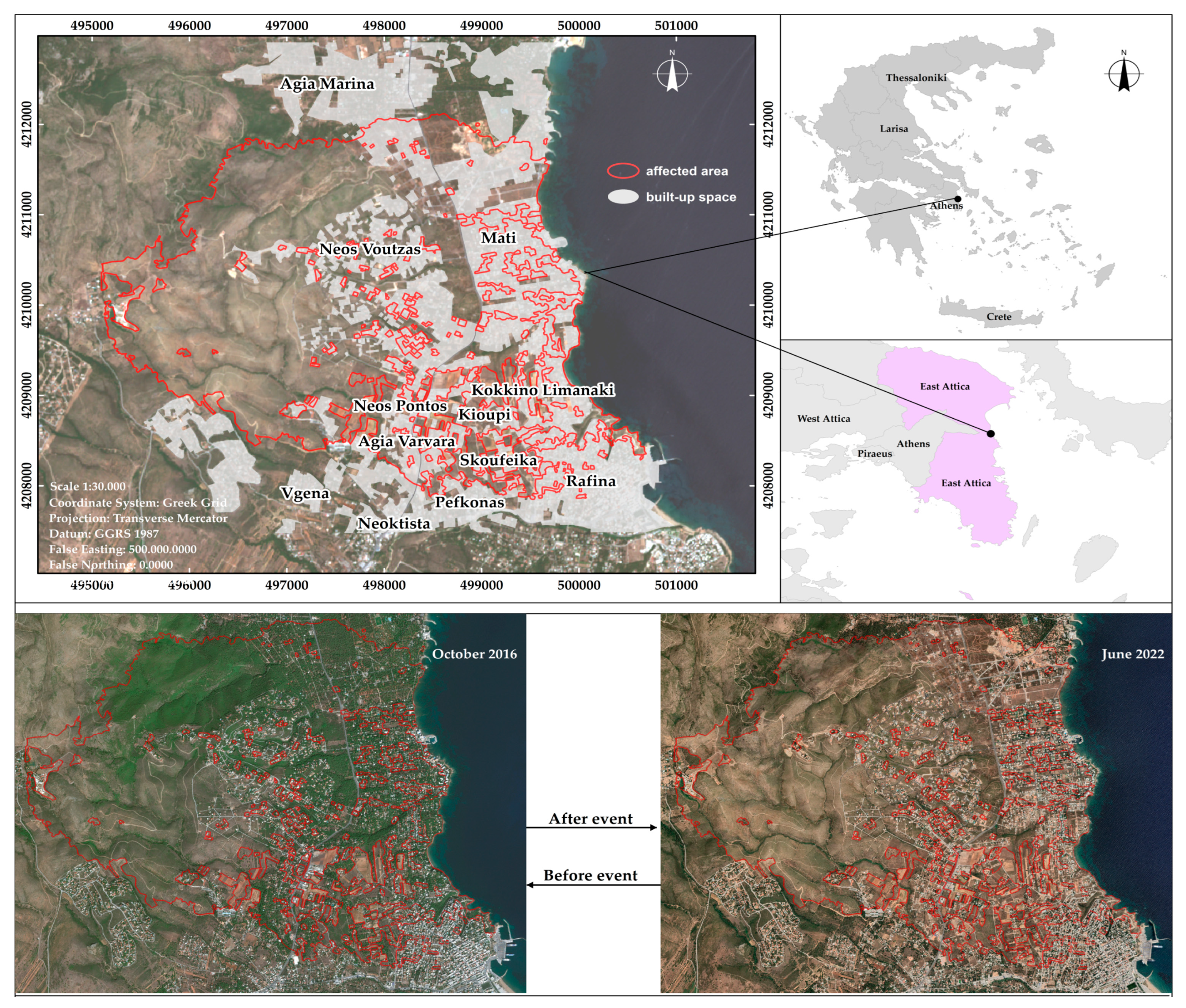
The study area spans the east coast of the Attica region, including the affected settlements of Neos Voutzas, Mati, Neos Pontos, Agia Varvara, Kokkino Limanaki, Kioupi Skoufeika, and Peukonas, as shown in Figure 3. The area is characterized as a mixed-area consisting of low-rise buildings, low vegetation, and bare land. The size of the burned area reached 13,000 acres approximately, where half of them residential, which is the main area of interest (AOI) of this research.
The topography of the area creates an intense network of streams starting from the hilly area in the west and ending up in the seaside Mati settlement in the east by crossing the rest of the settlements. This fact adds a higher pressure to the ground deformation phenomena, especially during intense rainstorms. Apart from the devastating fire event, an additional reason for choosing to study this area arises from its character as a recreational or second-housing area that is predominantly used during summertime along with its reputation as a seaside resort attracting many tourists every year.
According to Corine 2018, the land use in the study area primarily consists of a discontinuous urban fabric intertwined with complex cultivation patterns. In the northern region, the urban fabric aligns itself with a coniferous forest, while in the western part, it interfaces with sparsely vegetated areas. However, following the occurrence of a fire, the post-fire land use has transformed into a combination of discontinuous urban fabric and barren land.
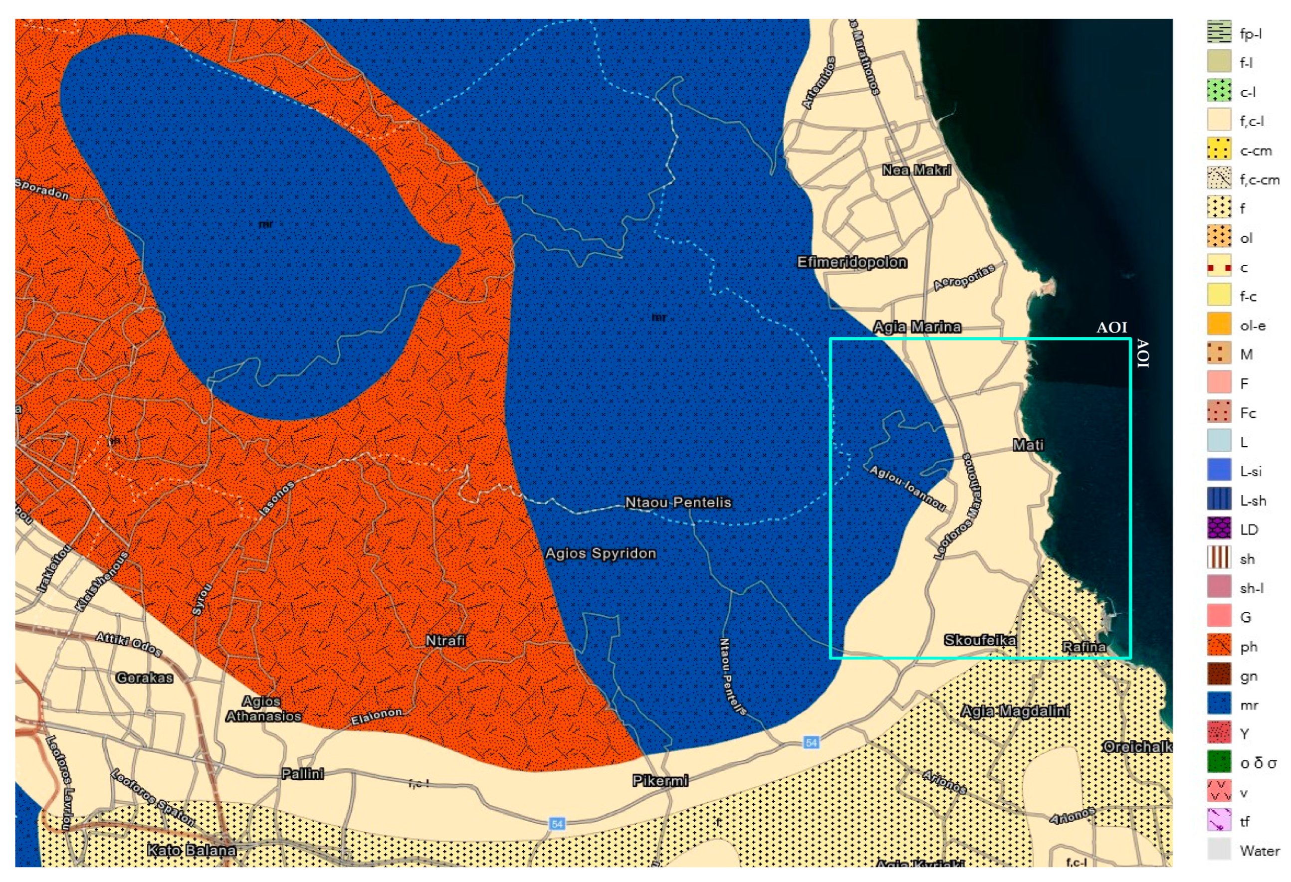
From a geological perspective, the fourth-generation sediments are loosely consolidated and composed of mixed phases as follows: clay silts, sands, pebbles, gravels, and variable-sized pebbles with fluctuating proportions, as shown in Figure 4.
These deposits are found in low-lying areas, valleys, and streams and originate from the weathering and erosion of older formations with diverse compositions. They often exhibit significant thickness, reaching several hundreds of meters, and show frequent and rapid changes in lithological composition and grain size distribution both horizontally and vertically within the formation.
They are characterized by moderate to high hydraulic conductivity and typically give rise to aquifers with a high potential and significant fluctuations. Due to their extensive surface distribution, many settlements across the country have developed on these deposits, often facing geotechnical issues such as settlement and soil displacement. They are susceptible to erosion and washing. Their physical and mechanical characteristics vary depending on the individual lithological composition and grain size distribution. Additionally, their behavior is influenced by factors beyond the aforementioned, including the deposit thickness and slope of the terrain (especially during dynamic loads).
They exhibit rapid lateral variations in lithological composition, leading to strong heterogeneity in the mechanical behavior of the formation on a larger scale.

2.2. Data

The data used in this research was acquired via the Sentinel-1 satellite and collected using the Alaska Vertex Hub (https://search.asf.alaska.edu accessed 10 May 2022). A total of 229 SAR SLC-IW images were collected from ascending and descending orbits using VV polarization. Furthermore, burn severity was calculated using two multispectral satellite images obtained from Sentinel-2, which were captured before and after the event. The details of the data are outlined in Table 1.
A high-resolution DSM was used as the external, which was derived from the Pleiades tri-stereo images acquired in 2016 for the topography component removal. Furthermore, the stream network was extracted via the DSM from the area’s topographic diagram (1:5000) obtained via the Hellenic Military Geographical Service (https://www.gys.gr/hmgs-topographic_en.html, accessed on 22 February 2023).

2.3. Method

Starting with the data preparation, it is required to subset the area of interest, update the orbit files for appropriate image coregistration, and estimate the coherence of all possible connections in the images’ space. Adopting a multi-master approach, the full graph connectivity was chosen and modified based on the coherence threshold of 0.35, aiming to minimize the processing time and keep the graph connected, as shown in Figure 5. The rationale behind the selection of this specific threshold was to identify the highest possible value for optimal connection minimization while also ensuring graph connectivity. The derived value of 0.35 proved to be the most suitable choice.
Indeed, the number of connections decreased from 6671 to 2572 for the ascending data and from 6329 to 1648 for the descending data. This shows that the most complex method is not always the most suitable for every application and study area. In our case, the excessive number of connections is unnecessary and modifying it via the selected coherence threshold appears to be a suitable approach with the additional benefit of saving processing time. Having defined the connection graph of the images, the preliminary analysis must be carried out while including the reflectivity map and amplitude dispersion index (1-sigma/mu) calculation.
For the preliminary geocoding procedure, a clearly visible pixel in the SAR images was selected as a ground control point (GCP) to geocode the dataset. The transfer of the external DEM in the SAR coordinates’ system is mandatory to complete the preprocessing stage.
Since we are dealing with Permanent Scatterers (PS) and Distributed Scatterers (DS) points, it is desirable to enhance the DS points’ Signal to Noise Ratio (SNR), improving the estimation of their parameters. To achieve it, a space adaptive filter is applied to extract the Statistically Homogeneous Pixels (SHP) only. To evaluate the likeness of the adjusting pixels, the amplitude time series was compared according to the Anderson–Darling statistical test [46], aiming to identify the reasonable clusters of similar pixels. The search window size, significance level, and connectivity were set at 25 × 7 (rg × az) for the ascending data and at 23 × 7 (rg × az) for the descending data, with 0.95 and 8 pixels, respectively. The dimensions of the search window used correspond to approximately a hectare, assuming this will yield a reliable estimation of the coherence values.
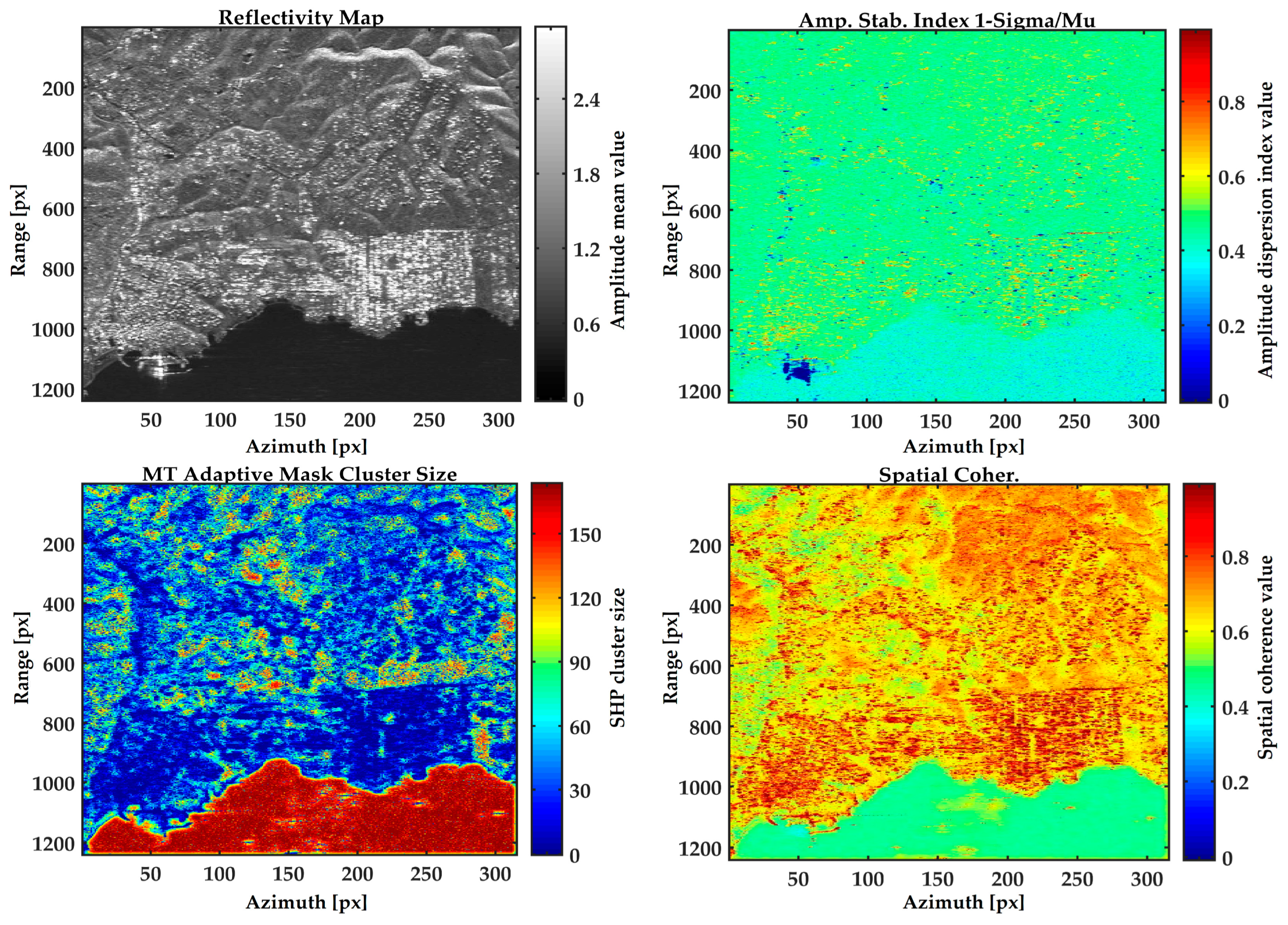
Next, the interferograms and spatial coherence were calculated and filtered using the multi-temporal adaptive mask. Figure 6 illustrates the reflectivity map, amplitude dispersion index, multi-temporal adaptive mask, and spatial coherence products. Contrasting the reflectivity map and adaptive mask cluster size, it becomes evident that the pixels with low amplitude values, likely corresponding to the DS points, tend to form larger clusters. Conversely, the pixels with high amplitude values, possibly indicative of the PS points, exhibit minimal changes or remain unchanged.
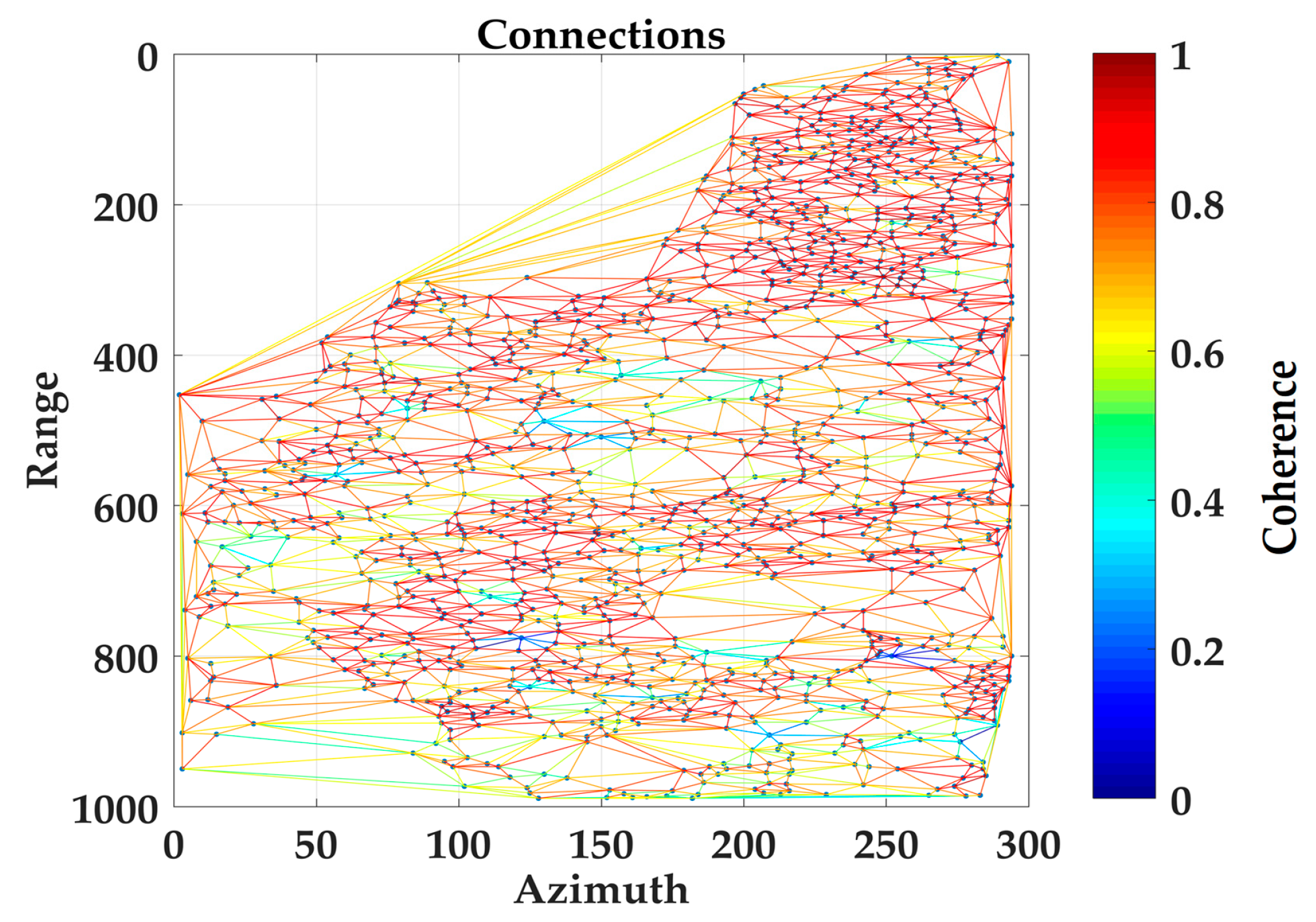
As the preprocessing was completed, PSI analysis was followed. A first set of Permanent Scatterer Candidate (PSC) points was selected based on the amplitude dispersion index (1-sigma/mu) plus the spatial coherence threshold of 1.5, assuming that this set is stable enough in time to estimate the atmospheric phase screen (APS). The triangulation network between the selected points, as shown in Figure 7 was implemented and the parameters as the deformation trend, residual height, and temporal coherence were computed in relation to a reference point. The reference point is a permanent GNSS reference station; therefore, it is considered to be quite stable. The PSC points present quite dense spatial distribution and high coherence connections that is desirable for the APS estimation. It must be noted that, during the APS calculation, images with low coherence and significant “phase jumps” in the calculated atmosphere were discarded from the time series data.
After estimating and evaluating APS, it is intriguing to explore the additional PSC points. To accomplish this, a second set of points was chosen utilizing the same indicator as mentioned earlier, but with a relaxed threshold. A reasonable value of 1.0 was employed to apply the multi-temporal PSI analysis. One more difference in this stage is the adaption of spatial coherence as a weight during the processing, aiming to maximize the number of measuring points. Since the parameters were calculated, the measuring points that showed temporal coherence equal to or higher than 0.8 were selected as the stable points to reliably estimate the deformation trend.
After extracting and assessing the consistency of the two velocity fields obtained from the ascending and descending datasets, two vector files representing the LOS deformation trend were created for the post-processing stage.
The deformation values were converted into absolute values and classified based on the conservation criticality index classes and the relative PS velocity range, as shown in Table 2 [47].
Inverse Distance Weighted (IDW) interpolation was implemented to identify and map the candidate deformation zones, setting a search radius distance of 60 m that selected based on a spatial autocorrelation via distance analysis using Morans I statistic, as shown in Figure 8.
Since the research deals with absolute deformation values, the point features from the ascending and descending orbits were merged for interpolation implementation.
Furthermore, the burn severity (dNBR) was calculated with the use of two Sentinel-2 images before and after the fire event. The severity is the outcome of the subtraction between the pre-fire and post-fire Normalized Burn Ratio (NBR), as described in Equation (1), and is classified based on the proposed table of the United States Geological Survey (USGS), as shown in Table 3 [48].
N B R = N I R S W I R ( N I R + S W I R ) ,
where NIR is the near infrared and SWIR is the short wave infrared.
Burn severity is used in developing emergency rehabilitation and restoration post-fire plans. It can be applied to estimate not only the soil burn severity, but also the likelihood of future downstream impacts due to flooding, landslides, and soil erosion.
Our proposed method for the combination of the deformation trend and burn severity is based on the reclassification of the two datasets on a scale from 1 to 5 and in Equation (2). The proposed equation will preserve the outcome in the same scale as the reclassified datasets (from 1 to 5). The initial component of the equation aims to delineate the spatially correlated regions within the two datasets by categorizing each zone with a hazard level ranging from 1 (low) to 5 (high). The subsequent segment of the equation functions as a weighting factor, particularly in cases where one dataset exhibits a maximum value of 5, while the other displays a minimum value of 1. A smaller numerical value corresponds to the reduced impact on the final outcome and vice versa. The addition of integer 1 serves to eliminate integer zero from the resulting decimal number, facilitating multiplication between the two equation components.
H i = d t × b s × 1 + N A D 2 ,
with Hi (hazard index) as the outcome, d t as the reclassified deformation trend, b s as the reclassified burn severity, and NAD as the normalized absolute difference between dt and bs, as shown in Equation (3).
N A D = d t b s d t + b s   ,
Equation (2) generates a new information layer about the hazard level and is classified into four classes (A to D) using the equal interval classification method, as shown in Table 4. The statistics of the result are presented in Table 5.
The minimum and maximum values pertain to the result of multiplying the two components of the equation and correspond to the hazard level category. The mean and standard deviation values suggest that the study area is largely classified as having a low hazard level.

3. Results

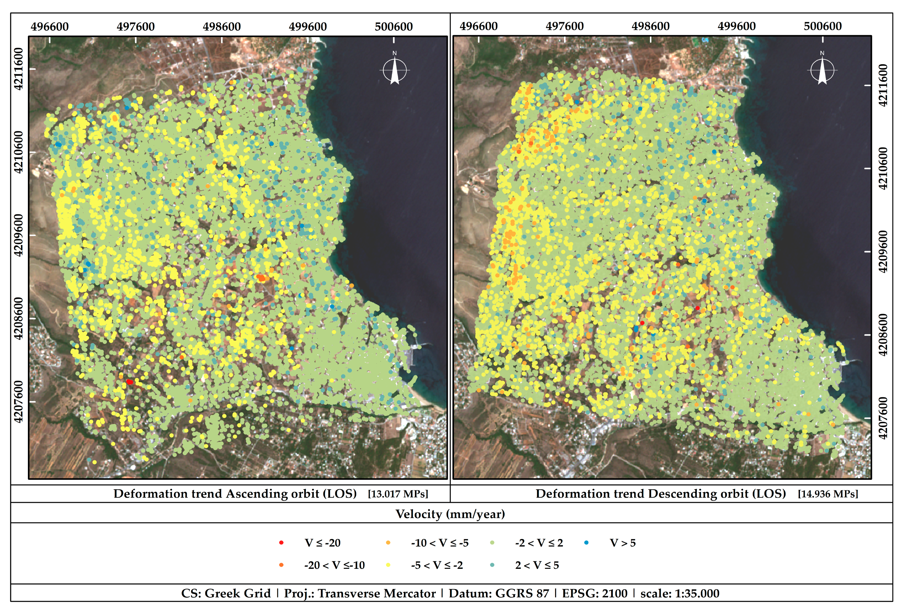
The first aspect of this research was the calculation of the deformation trend and the zoning of the measuring points via spatial interpolation to generate the first information layer for the research objective. Figure 9 shows the deformation trend of the measuring points per orbit and Figure 10 shows the deformation classes after the point features are converted to absolute values, merged, and interpolated.
To assess the consistency between the ascending and descending datasets, we selected adjacent points within a 5 m distance, close to the range resolution of the system. A total of 2441 measurement points were identified for evaluating their statistics, as presented in Table 6.
Based on the statistics, the initial assessment of the two datasets can be deemed satisfactory, as their values are sufficiently close. The standard deviation (std) for both datasets is approximately 1 mm/yr. Kurtosis and skewness offer insights into the shape and characteristics of the distribution of the datasets. The skewness of both datasets is nearly zero, exhibiting slightly negative values that suggest an almost symmetrical distribution. However, there exists a slightly elongated tail on the left side of the distribution due to the variations between the minimum and maximum values. Similarly, the kurtosis value approximates zero, implying a normal distribution for both datasets.
Based on the comparison outcomes, the standard deviation of the mean error and the root mean square error are slightly high at 1.24 and 1.26 mm/yr, respectively. Since we are estimating the trend of LOS deformation, these values indicate how closely or distantly the target has moved from the satellite sensor. In other words, if there is deformation along the horizontal axis, opposite values are derived for the ascending and descending data. This is supported via the standard deviation of the mean absolute error (MAE), which represents the variability of absolute errors around the MAE average value, regardless of the error direction. The standard deviation of MAE presents a value of 0.74 mm/yr, which can be considered sufficient. In addition, the Standard Error measures the precision of the MAE estimation. A value of 0.01 indicates a relatively well-estimated MAE. In summary, the assessment of the derived velocity fields demonstrates a high consistency between the ascending and descending datasets.
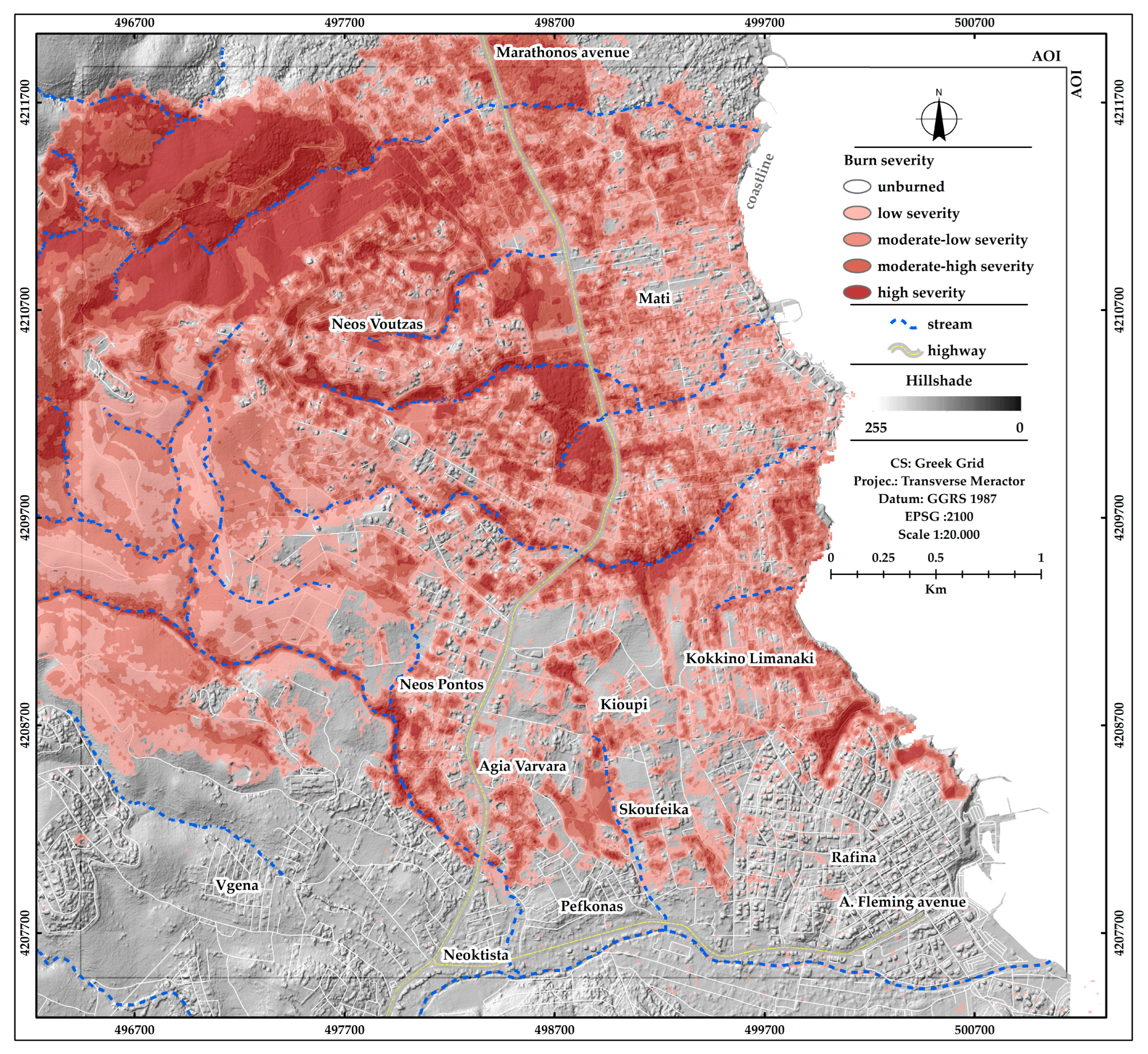
As the deformation zones were mapped, the second research aspect is followed, that is the estimation of burn severity with the use of Sentinel-2 images, as shown in Figure 11. The assumption behind this assessment is that higher burn severity leads to greater degradation of soil stability. This means that burn severity adds a measurable risk factor by itself.
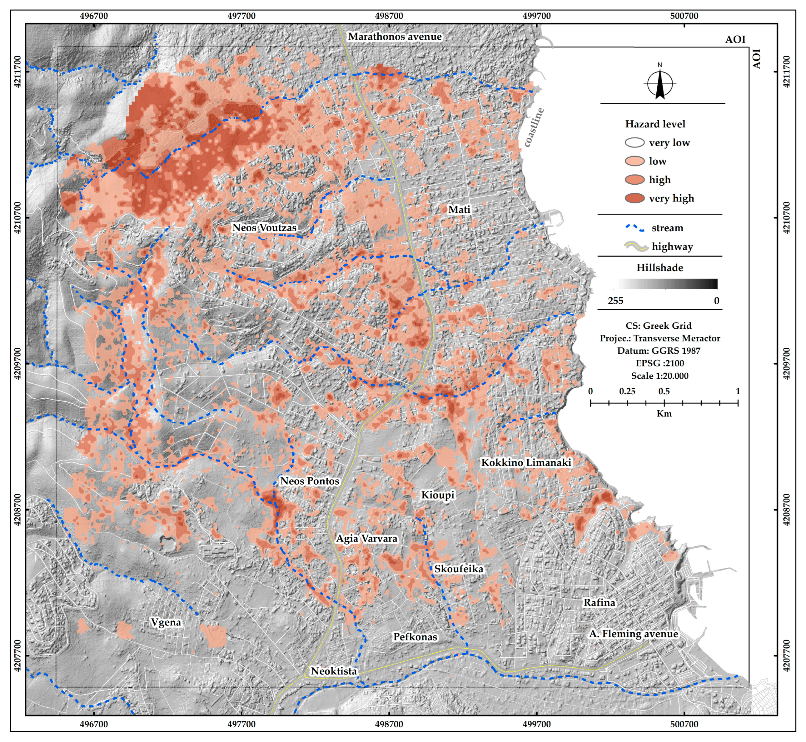
As the two main aspects of this research are already established and assuming that they are considerable factors for planning a future urban expansion or for monitoring and maintaining the existing urban fabric, the combination between them via the proposed method seems appropriate to create the final layer of information that presents the classified ground risk zones, as shown in Figure 12.
Based on the results of the proposed method, numerous risk zones have been identified. It is evident that the high and very high hazard level zones have been aligned with the stream network. It is a fact that in many cases, residential buildings are being constructed in close proximity to the stream edges. However, based on the research findings, these areas are deemed unsuitable for residential purposes. The necessity for establishing a buffer zone, which would restrict construction activities, is becoming increasingly apparent. Two notable examples are illustrated in Figure 13.
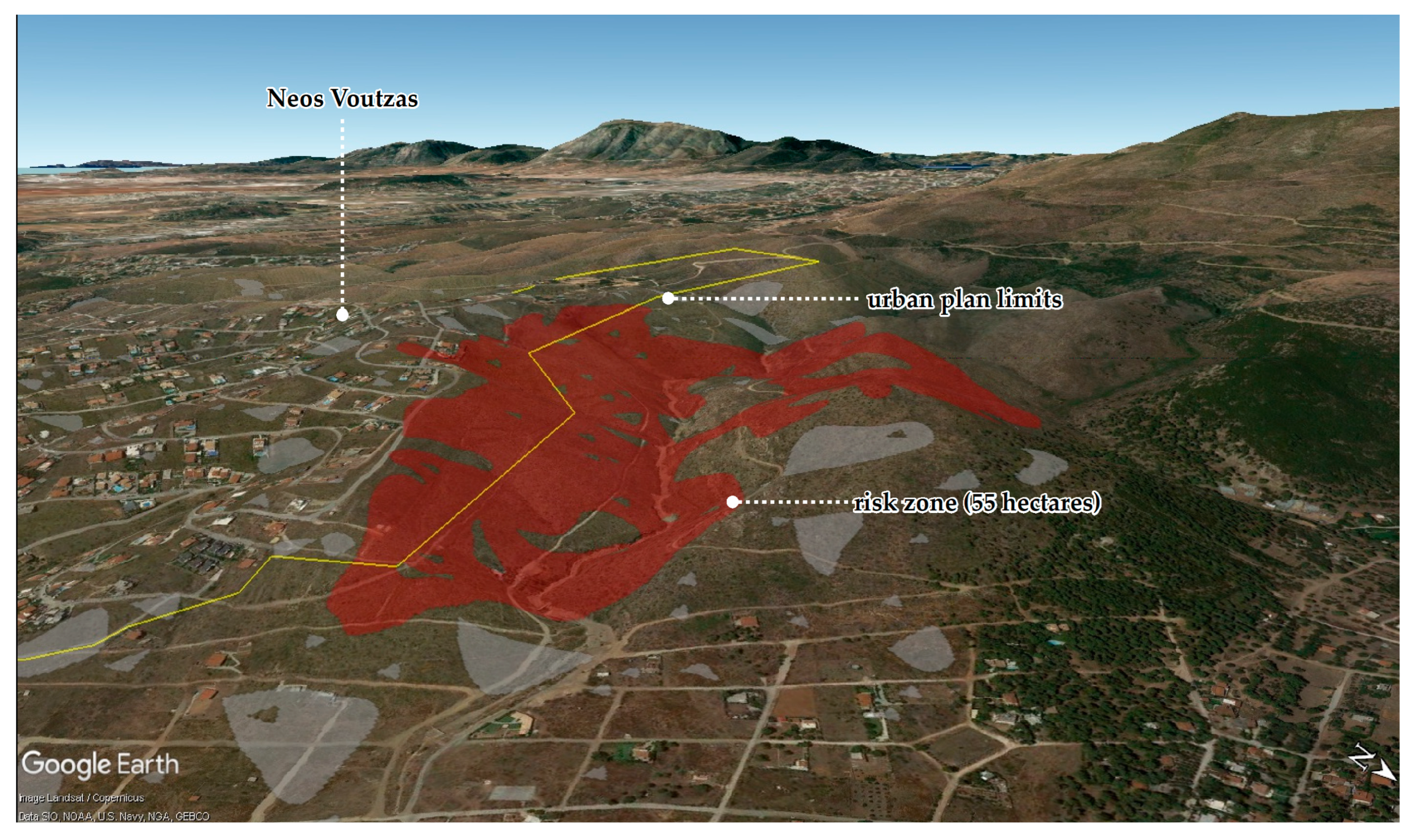
Notably, the northwest side of the study area is of significant interest as it encompasses a substantial area characterized by high and very high hazard levels. This region was densely vegetated prior to the fire but has now been completely stripped of its vegetation, transforming into a bare landscape post-fire. Given its expanse of 55 hectares and its proximity to the urban plan limits, this zone is considered unsuitable for urban expansion. We extracted this zone and illustrated it in Google Earth Pro, as shown in Figure 14.

4. Discussion

The first aspect of this research was to investigate the potential ground deformation phenomena in the affected area. The use of a multi-master PSI approach maximized the number of measuring points and, by extension, they presented an ideal spatial distribution. The proposed method exploits the deformation trend and burn severity by combining them simply and effectively. It seems that the combination of the ground conditions, topography, and the fire impact has contributed to the appearance of high and very high level hazard zones. The vulnerability of our approach lies in the lack of official data for accurately assessing its precision. However, considering the demonstrable accuracy of the PSI technique and the evaluation of burn severity as indicated in the existing literature, we are operating under the assumption that our proposed method produces dependable outcomes.
Concerning the research findings, noticeable risk zones were detected that lack an appropriate urban plan. Moreover, a sizeable risk zone was detected in the northwest boundaries of the study area characterized by a steep topography. Furthermore, this location is identified as unsuitable for urban expansion. Another finding is the intense proximity of the risk zones with the streams. Due to the area’s topography, there is a dense network of streams transcending the urban fabric, which is in conjunction with the illegal and anarchic construction settings of at-risk existing buildings. The identified risk zones in the study area show a considerable proximity to certain sections of the main avenue passing through the study area, Marathonos Avenue. It is a major and relatively new infrastructure, which was completed in 2004, that connects the east sector of the Attica region with Athens. Due to the high significance of this infrastructure, monitoring and timely maintenance are crucial for an appropriate function.
In a nutshell, remarkable hazard zones have been detected in the study area. Considering the short post-fire period (5 years) that has passed until today, we can claim that the area requires permanent monitoring. This research has mapped the candidate hazard zones that allow the use of targeted monitoring that offers a positive impact on decision making and the immediate appropriate interventions. The research findings could be used as a useful spatial information layer in the new urban plan that is currently under preparation or for the zoning of buildings and public utility services. The proposed method is applicable in anyone affected in the study area after a fire event.
Since the Hellenic cadastre provides the land parcels as open-source spatial information, there is the possibility to examine the research outcome on a parcel scale creating a piece of extra valuable information for future building constructions.

5. Conclusions

PSI is a powerful, efficient, and cost-effective technique for ground deformation studies. It offers the possibility to study remotely large areas with a short processing time. The outcome has a high value for risk assessment and urban planning especially in residential landscapes, since prevention is the key to avoiding unwanted situations. In our case, significantly high and very high hazard zones were detected that emerged as a major problem for the built-up space. Furthermore, it is worth underlining the intense adjacency of very high hazard level zones with the streams. The research findings highlight the importance of the permanent future monitoring of the study area.
Our future work will focus on the study of the non-linear deformation phenomena aiming to create a comprehensive picture of the study area. Moreover, we eagerly await the official data that will enable us to assess the effectiveness of our proposed method.

Author Contributions

Conceptualization, V.L. and I.F.; Methodology, V.L.; Writing–original draft, V.L. and D.S.; Visualization, V.L.; Supervision, D.S. All authors have read and agreed to the published version of the manuscript.

Funding

This research is co-financed by Greece and the European Union (European Social FundESF) through the Operational Program «Human Resources Development, Education and Lifelong Learning» in the context of the project “Strengthening Human Resources Research Potential via Doctorate Research” (MIS-5000432), implemented by the State Scholarships Foundation (IKΥ).

Data Availability Statement

Publicly available datasets were analyzed in this study. Sentinel-1 data are available via the ASF data search Vertex (https://search.asf.alaska.edu/#/, accessed on 28 September 2022). The vector data (burned and built-up areas) are available via the Copernicus Emergency Management Service-Mapping portal. (https://emergency.copernicus.eu/mapping/download/163143/EMSR300_02RAFINA_01DELINEATION_MAP_v2_vector.zip, accessed on 22 February 2023).

Acknowledgments

This work has made use of the data from the European Space Agency (ESA) through the Sentinel-1 mission. The authors would like to thank the SARPROZ team for providing their valuable software for research purposes. Pleiades-1B tri-stereo raw data were delivered under the supersite «Enceladus Supersite Goals» initiative via the Enceladus partner GEOSYSTEMS HELLAS SA.

Conflicts of Interest

The authors declare no conflict of interest.

References

  1. Tsilimigkas, G.; Stathakis, D.; Pafi, M. Evaluating the Land Use Patterns of Medium-Sized Hellenic Cities. Urban Res. Pract. 2016, 9, 181–203. [Google Scholar] [CrossRef]
  2. Shakesby, R.A. Post-Wildfire Soil Erosion in the Mediterranean: Review and Future Research Directions. Earth Sci. Rev. 2011, 105, 71–100. [Google Scholar] [CrossRef]
  3. Deligiannakis, G.; Pallikarakis, A.; Papanikolaou, I.; Alexiou, S.; Reicherter, K. Detecting and Monitoring Early Post-Fire Sliding Phenomena Using UAV–SfM Photogrammetry and t-LiDAR-Derived Point Clouds. Fire 2021, 4, 87. [Google Scholar] [CrossRef]
  4. Efthimiou, N.; Psomiadis, E.; Panagos, P. Fire Severity and Soil Erosion Susceptibility Mapping Using Multi-Temporal Earth Observation Data: The Case of Mati Fatal Wildfire in Eastern Attica, Greece. Catena 2020, 187, 104320. [Google Scholar] [CrossRef]
  5. Ferretti, A.; Prati, C.; Rocca, F. Permanent Scatterers in SAR Interferometry. IEEE Trans. Geosci. Remote Sens. 2001, 39, 8–20. [Google Scholar] [CrossRef]
  6. Berardino, P.; Fornaro, G.; Lanari, R.; Sansosti, E. A New Algorithm for Surface Deformation Monitoring Based on Small Baseline Differential SAR Interferograms. IEEE Trans. Geosci. Remote Sens. 2002, 40, 2375–2383. [Google Scholar] [CrossRef]
  7. Hooper, A.J.; Zebker, H.A.; Segall, P.; Kampes, B.M. A New Method for Measuring Deformation on Volcanoes and Other Natural Terrains Using InSAR Persistent Scatterers. Geophys. Res. Lett. 2004, 31, L23611. [Google Scholar] [CrossRef]
  8. Hooper, A. A Multi-Temporal InSAR Method Incorporating Both Persistent Scatterer and Small Baseline Approaches. Geophys. Res. Lett. 2008, 35, L16302. [Google Scholar] [CrossRef]
  9. Perissin, D.; Wang, T. Repeat-Pass SAR Interferometry With Partially Coherent Targets. IEEE Trans. Geosci. Remote Sens. 2012, 50, 271–280. [Google Scholar] [CrossRef]
  10. Ferretti, A.; Fumagalli, A.; Novali, F.; Prati, C.; Rocca, F.; Rucci, A. A New Algorithm for Processing Interferometric Data-Stacks: SqueeSAR. IEEE Trans. Geosci. Remote Sens. 2011, 49, 3460–3470. [Google Scholar] [CrossRef]
  11. HO TONG MINH, D.; Hanssen, R.; Rocca, F. Radar Interferometry: 20 Years of Development in Time Series Techniques and Future Perspectives. Remote Sens. 2020, 12, 1364. [Google Scholar] [CrossRef]
  12. Prats-Iraola, P.; Nannini, M.; Yague-Martinez, N.; Scheiber, R.; Minati, F.; Vecchioli, F.; Costantini, M.; Borgstrom, S.; De Martino, P.; Siniscalchi, V.; et al. Sentinel-1 Tops Interferometric Time Series Results and Validation. In Proceedings of the 2016 IEEE International Geoscience and Remote Sensing Symposium (IGARSS), Beijing, China, 10–15 July 2016; pp. 3894–3897. [Google Scholar]
  13. Cigna, F.; Esquivel Ramírez, R.; Tapete, D. Accuracy of Sentinel-1 PSI and SBAS InSAR Displacement Velocities against GNSS and Geodetic Leveling Monitoring Data. Remote Sens. 2021, 13, 4800. [Google Scholar] [CrossRef]
  14. Qin, Y.; Perissin, D. Monitoring Ground Subsidence in Hong Kong via Spaceborne Radar: Experiments and Validation. Remote Sens. 2015, 7, 10715–10736. [Google Scholar] [CrossRef]
  15. Razi, P.; Sumantyo, J.T.S.; Perissin, D.; Kuze, H.; Chua, M.Y.; Panggabean, G.F. 3D Land Mapping and Land Deformation Monitoring Using Persistent Scatterer Interferometry (PSI) ALOS PALSAR: Validated by Geodetic GPS and UAV. IEEE Access 2018, 6, 12395–12404. [Google Scholar] [CrossRef]
  16. Letsios, V.; Faraslis, I.; Stathakis, D. Monitoring Building Activity by Persistent Scatterer Interferometry. Remote Sens. 2023, 15, 950. [Google Scholar] [CrossRef]
  17. Arangio, S.; Calò, F.; Di Mauro, M.; Bonano, M.; Marsella, M.; Manunta, M. An Application of the SBAS-DInSAR Technique for the Assessment of Structural Damage in the City of Rome. Struct. Infrastruct. Eng. 2014, 10, 1469–1483. [Google Scholar] [CrossRef]
  18. Khan, R.; Li, H.; Afzal, Z.; Basir, M.; Arif, M.; Hassan, W. Monitoring Subsidence in Urban Area by PSInSAR: A Case Study of Abbottabad City, Northern Pakistan. Remote Sens. 2021, 13, 1651. [Google Scholar] [CrossRef]
  19. Heleno, S.I.N.; Oliveira, L.G.S.; Henriques, M.J.; Falcão, A.P.; Lima, J.N.P.; Cooksley, G.; Ferretti, A.; Fonseca, A.M.; Lobo-Ferreira, J.P.; Fonseca, J.F.B.D. Persistent Scatterers Interferometry Detects and Measures Ground Subsidence in Lisbon. Remote Sens. Environ. 2011, 115, 2152–2167. [Google Scholar] [CrossRef]
  20. Perissin, D.; Wang, T. Time-Series InSAR Applications Over Urban Areas in China. IEEE J. Sel. Top. Appl. Earth Obs. Remote Sens. 2011, 4, 92–100. [Google Scholar] [CrossRef]
  21. Lazecky, M.; Hlavacova, I.; Bakon, M.; Sousa, J.J.; Perissin, D.; Patricio, G. Bridge Displacements Monitoring Using Space-Borne X-Band SAR Interferometry. IEEE J. Sel. Top. Appl. Earth Obs. Remote Sens. 2017, 10, 205–210. [Google Scholar] [CrossRef]
  22. Ruiz-Armenteros, A.M.; Lazecky, M.; Hlaváčová, I.; Bakoň, M.; Delgado, J.M.; Sousa, J.J.; Lamas-Fernández, F.; Marchamalo, M.; Caro-Cuenca, M.; Papco, J.; et al. Deformation Monitoring of Dam Infrastructures via Spaceborne MT-InSAR. The Case of La Viñuela (Málaga, Southern Spain). Procedia Comput. Sci. 2018, 138, 346–353. [Google Scholar] [CrossRef]
  23. Milillo, P.; Giardina, G.; Perissin, D.; Milillo, G.; Coletta, A.; Terranova, C. Pre-Collapse Space Geodetic Observations of Critical Infrastructure: The Morandi Bridge, Genoa, Italy. Remote Sens. 2019, 11, 1403. [Google Scholar] [CrossRef]
  24. Roccheggiani, M.; Piacentini, D.; Tirincanti, E.; Perissin, D.; Menichetti, M. Detection and Monitoring of Tunneling Induced Ground Movements Using Sentinel-1 SAR Interferometry. Remote Sens. 2019, 11, 639. [Google Scholar] [CrossRef]
  25. Cigna, F.; Tapete, D. Satellite InSAR Survey of Structurally-Controlled Land Subsidence Due to Groundwater Exploitation in the Aguascalientes Valley, Mexico. Remote Sens. Environ. 2021, 254, 112254. [Google Scholar] [CrossRef]
  26. Zhang, Y.; Gong, H.; Li, X.; Liu, T.; Yang, W.; Chen, B.; Li, A.; Su, Y. Insar Analysis of Land Subsidence Caused by Groundwater Exploitation in Changping, Beijing, China. In Proceedings of the IGARSS 2008—2008 IEEE International Geoscience and Remote Sensing Symposium, Boston, MA, USA, 7–11 July 2008; Volume 2, pp. II–1247–II–1250. [Google Scholar]
  27. Normand, J.C.L.; Heggy, E. InSAR Assessment of Surface Deformations in Urban Coastal Terrains Associated With Groundwater Dynamics. IEEE Trans. Geosci. Remote Sens. 2015, 53, 6356–6371. [Google Scholar] [CrossRef]
  28. Cigna, F.; Tapete, D. Sentinel-1 InSAR Assessment of Present-Day Land Subsidence Due to Exploitation of Groundwater Resources in Central Mexico. In Proceedings of the IGARSS 2020—2020 IEEE International Geoscience and Remote Sensing Symposium, Waikoloa, HI, USA, 26 September–2 October 2020; pp. 4215–4218. [Google Scholar]
  29. Przyłucka, M.; Herrera, G.; Graniczny, M.; Colombo, D.; Béjar-Pizarro, M. Combination of Conventional and Advanced DInSAR to Monitor Very Fast Mining Subsidence with TerraSAR-X Data: Bytom City (Poland). Remote Sens. 2015, 7, 5300–5328. [Google Scholar] [CrossRef]
  30. Botsialas, K.; Ravde, V.; Falomi, A.; Meloni, F.; Boldrini, N.; Bellotti, F.; Leoni, L.; Coli, N. The Integrated Usage of Ground-Based and Satellite SAR, along with 3D Structural Modelling in Titania: Creating a Link between Short and Long—Term Slope Stability Hazard Management. IOP Conf. Ser. Earth Environ. Sci. 2021, 833, 12143. [Google Scholar] [CrossRef]
  31. Paradella, W.R.; Ferretti, A.; Mura, J.C.; Colombo, D.; Gama, F.F.; Tamburini, A.; Santos, A.R.; Novali, F.; Galo, M.; Camargo, P.O.; et al. Mapping Surface Deformation in Open Pit Iron Mines of Carajás Province (Amazon Region) Using an Integrated SAR Analysis. Eng. Geol. 2015, 193, 61–78. [Google Scholar] [CrossRef]
  32. Del Soldato, M.; Solari, L.; Raspini, F.; Bianchini, S.; Ciampalini, A.; Montalti, R.; Ferretti, A.; Pellegrineschi, V.; Casagli, N. Monitoring Ground Instabilities Using SAR Satellite Data: A Practical Approach. ISPRS Int. J. Geo-Inf. 2019, 8, 307. [Google Scholar] [CrossRef]
  33. Carlà, T.; Intrieri, E.; Raspini, F.; Bardi, F.; Farina, P.; Ferretti, A.; Colombo, D.; Novali, F.; Casagli, N. Perspectives on the Prediction of Catastrophic Slope Failures from Satellite InSAR. Sci. Rep. 2019, 9, 14137. [Google Scholar] [CrossRef]
  34. Raspini, F.; Ciampalini, A.; Del Conte, S.; Lombardi, L.; Nocentini, M.; Gigli, G.; Ferretti, A.; Casagli, N. Exploitation of Amplitude and Phase of Satellite SAR Images for Landslide Mapping: The Case of Montescaglioso (South Italy). Remote Sens. 2015, 7, 14576–14596. [Google Scholar] [CrossRef]
  35. Cohen-Waeber, J.; Bürgmann, R.; Chaussard, E.; Giannico, C.; Ferretti, A. Spatiotemporal Patterns of Precipitation-Modulated Landslide Deformation From Independent Component Analysis of InSAR Time Series. Geophys. Res. Lett. 2018, 45, 1878–1887. [Google Scholar] [CrossRef]
  36. Costantini, M.; Ferretti, A.; Minati, F.; Falco, S.; Trillo, F.; Colombo, D.; Novali, F.; Malvarosa, F.; Mammone, C.; Vecchioli, F.; et al. Analysis of Surface Deformations over the Whole Italian Territory by Interferometric Processing of ERS, Envisat and COSMO-SkyMed Radar Data. Remote Sens. Environ. 2017, 202, 250–275. [Google Scholar] [CrossRef]
  37. Lagios, E.; Sakkas, V.; Novali, F.; Bellotti, F.; Ferretti, A.; Vlachou, K.; Dietrich, V. SqueeSARTM and GPS Ground Deformation Monitoring of Santorini Volcano (1992–2012): Tectonic Implications. Tectonophysics 2013, 594, 38–59. [Google Scholar] [CrossRef]
  38. Chua, K.M.; Wan, Q.; Liew, S.C.; Thouret, J.-C. Persistent Scatterer InSAR for Monitoring Active Volcanoes: Measuring Deformation at Merapi Using ALOS PALSAR Data. In Proceedings of the 2015 IEEE 5th Asia-Pacific Conference on Synthetic Aperture Radar (APSAR), Singapore, 1–4 September 2015; pp. 859–861. [Google Scholar]
  39. Albino, F.; Biggs, J.; Lazecký, M.; Maghsoudi, Y. Routine Processing and Automatic Detection of Volcanic Ground Deformation Using Sentinel-1 InSAR Data: Insights from African Volcanoes. Remote Sens. 2022, 14, 5703. [Google Scholar] [CrossRef]
  40. Pezzo, G.; Palano, M.; Beccaro, L.; Tolomei, C.; Albano, M.; Atzori, S.; Chiarabba, C. Coupling Flank Collapse and Magma Dynamics on Stratovolcanoes: The Mt. Etna Example from InSAR and GNSS Observations. Remote Sens. 2023, 15, 847. [Google Scholar] [CrossRef]
  41. Meng, Z.; Shu, C.; Yang, Y.; Wu, C.; Dong, X.; Wang, D.; Zhang, Y. Time Series Surface Deformation of Changbaishan Volcano Based on Sentinel-1B SAR Data and Its Geological Significance. Remote Sens. 2022, 14, 1213. [Google Scholar] [CrossRef]
  42. Filatov, A.; Evtyushkin, A.; Bryksin, V. Some Results of Long Term Geodynamic Monitoring of Oil and Gas Fields and Power Engineering Infrastructure Using ENVISAT and ALOS SAR Data. In Proceedings of the 2013 Asia-Pacific Conference on Synthetic Aperture Radar (APSAR), Tsukuba, Japan, 23–27 September 2013; pp. 181–184. [Google Scholar]
  43. Fatholahi, S.N.; He, H.; Wang, L.; Syed, A.; Li, J. Monitoring Surface Deformation Over Oilfield Using MT-Insar and Production Well Data. In Proceedings of the 2021 IEEE International Geoscience and Remote Sensing Symposium IGARSS, Brussels, Belgium, 11–16 July 2021; pp. 2298–2301. [Google Scholar]
  44. Comola, F.; Janna, C.; Lovison, A.; Minini, M.; Tamburini, A.; Teatini, P. Efficient Global Optimization of Reservoir Geomechanical Parameters Based on Synthetic Aperture Radar-Derived Ground Displacements. Geophysics 2016, 81, M23–M33. [Google Scholar] [CrossRef]
  45. Perissin, D.; Wang, Z.; Wang, T. SARPROZ InSAR Tool for Urban Subsidence/Manmade Structure Stability Monitoring in China. In Proceedings of the ISRSE 2011, Sydney, Australia, 10–15 April 2011. [Google Scholar]
  46. Wang, J.; Wang, C.; Tang, Y.; Zhang, H.; Duan, W.; Dong, L. Investigation for the Surface Deformation of Tanggula Mountain Permafrost Using Distributed Scatterer INSAR. In Proceedings of the 2021 IEEE International Geoscience and Remote Sensing Symposium IGARSS, Brussels, Belgium, 11–16 July 2021; pp. 5358–5361. [Google Scholar]
  47. Pratesi, F.; Tapete, D.; Terenzi, G.; Ventisette, C.; Moretti, S. Rating Health and Stability of Engineering Structures via Classification Indexes of InSAR Persistent Scatterers. Int. J. Appl. Earth Obs. Geoinf. 2015, 40, 81–90. [Google Scholar] [CrossRef]
  48. Keeley, J.E. Fire Intensity, Fire Severity and Burn Severity: A Brief Review and Suggested Usage. Int. J. Wildland Fire 2009, 18, 116–126. [Google Scholar] [CrossRef]
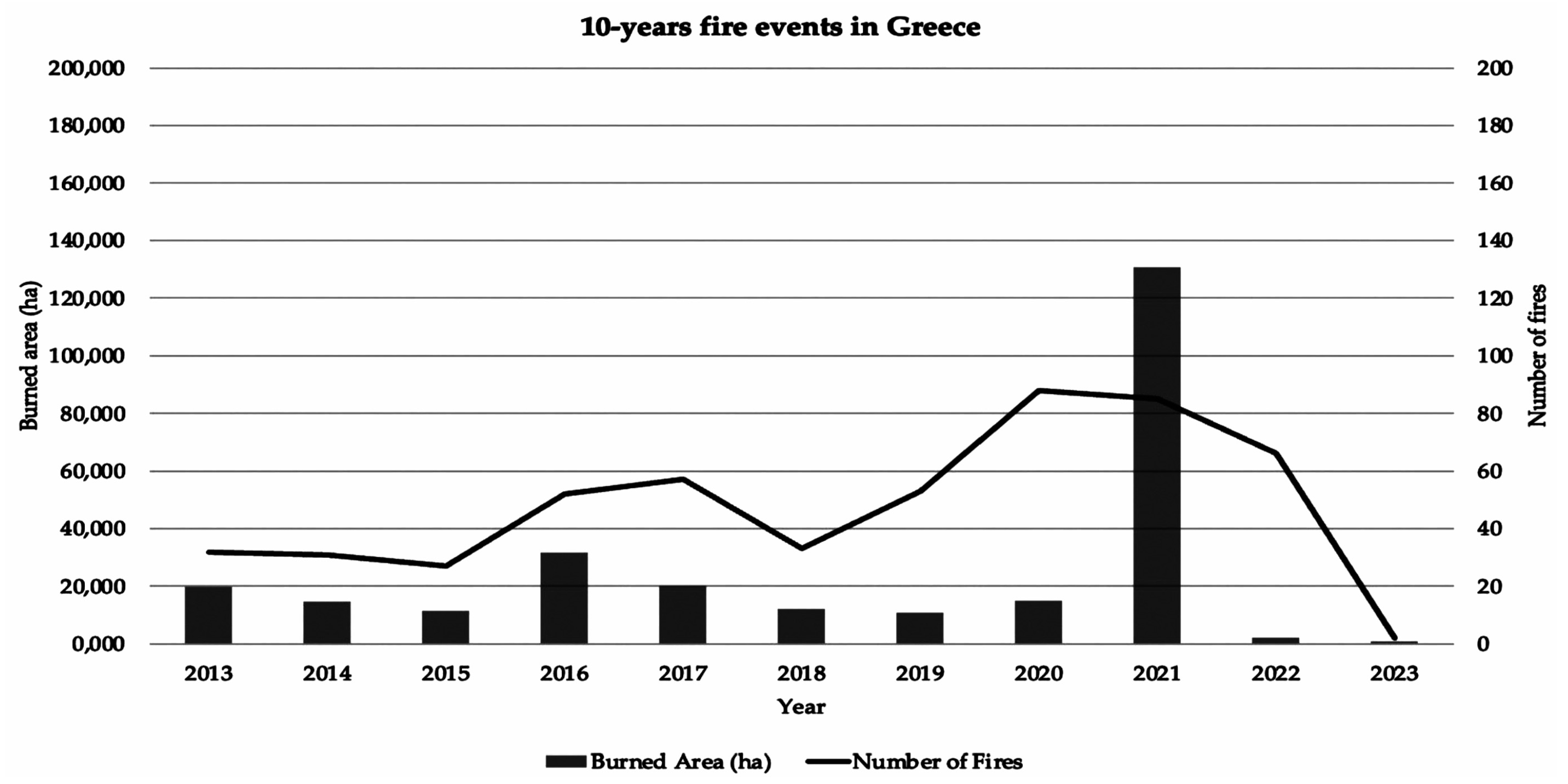
Figure 1. Official data about fires in Greece for the 10 last years. The bars correspond to burned areas in hectares and the line corresponds to the number of fires. The data is provided by the EFFIS.
Remotesensing 15 04598 g001
Figure 2. Residential building subsidence occurred at the beginning of September 2022 in Neos Voutzas following an intense rainstorm. The images are sourced from the archive of the Hellenic state television (https://www.ertnews.gr/tag/neos-voytzas/, accessed on 3 August 2023).
Remotesensing 15 04598 g002
Figure 3. Locator map. In the upper left part, the red color corresponds to the burned area, and the grey color to the built-up area. The lower part illustrates two satellite images before and after the event. The vector of the burned and built-up areas (red line) was obtained via the Copernicus Emergency Management Service-Mapping portal. (https://emergency.copernicus.eu/mapping/download/163143/EMSR300_02RAFINA_01DELINEATION_MAP_v2_vector.zip, accessed on 22 February 2023).
Remotesensing 15 04598 g003
Figure 4. Geotechnical map in a scale 1:500,000 of the study area. The data provided by the Hellenic service of geological and mineral research (https://www.eagme.gr/, accessed on 3 August 2023).
Remotesensing 15 04598 g004
Figure 5. SAR images of full graph connection. All the dots are line connected, ensuring the connectivity of the full graph. The color lines represent the coherence of each connection. The left and right graphs correspond to the ascending and descending data, respectively.
Remotesensing 15 04598 g005
Figure 6. Generated products from ascending orbit during data preparation for PSI analysis. Upper left, upper right, down left, and down right are the reflectivity map, amplitude dispersion index, multi-temporal adaptive mask cluster size, and spatial coherence, respectively.
Remotesensing 15 04598 g006
Figure 7. Triangulation network between the selected points for APS estimation. The colored lines represent the coherence of each connection.
Remotesensing 15 04598 g007
Figure 8. Graphical representation of spatial autocorrelation via distance analysis. The number of distance bands and distance increment are 30 and 20, respectively. The main peak corresponds to 60 m distance.
Remotesensing 15 04598 g008
Figure 9. Measurement points (PS and DS) in the study area. On the left is the result from ascending data and on the right from descending data. The letter “V” within the legend signifies velocity.
Remotesensing 15 04598 g009
Figure 10. Deformation zones derived via interpolation. The data is classified according to Table 2. Class A is illustrated with no color for a better representation of the other classes since it is considered as a stable area. The hillshade representation of the high resolution Pleiades DSM was used as a basemap.
Remotesensing 15 04598 g010
Figure 11. Map of burn severity level. The data is classified based on Table 3. Unburned areas are illustrated with no color for a better representation of the other classes.
Remotesensing 15 04598 g011
Figure 12. Map of the detected hazard zones via the proposed method. An intense zone is detected on the northwest side of the study area, toNeos Voutzas settlement.
Remotesensing 15 04598 g012
Figure 13. Examples of residential buildings in proximity with the stream edges. The areas of high and very high risk are depicted in red color. The impacted buildings are indicated by the yellow circles. The basemap is the 3D Google Earth Pro model.
Remotesensing 15 04598 g013
Figure 14. Zoom into the sizeable risk zone on the northwest side of the study area, illustrated with red color. The remaining zones are displayed in grey color. The yellow line presents the urban plan limits provided by the Hellenic Ministry of the Environment and Energy through e-poleodomia platform (http://gis.epoleodomia.gov.gr/, accessed on 3 March 2023). The zone is located on the slopes of the stream. The basemap is the Google Earth Pro 3D model.
Remotesensing 15 04598 g014
Table 1. Data description.
SAR ParametersAscendingDescending
Satellite SensorSentinel-1ASentinel-1A
Number of Images116113
Orbit1027
Swath and PolarizationIW2/VVIW1/VV
Sensing Period10 August 2018/7 August 20224 August 2018/1 August 2022
Rg × Az sampling (m.)3.67 × 13.934.17 × 13.96
Wavelength (cm.)5.555.55
Incidence angle (deg.)4033
Temporal Baseline (days)1212
Muli-Spectral parametersPre-firePost-fire
SatelliteSentinel-2BSentinel-2A
Number of Images11
Sensing Period5 July 201819 August 2018
Processing levelLevel-2ALevel-2A
Pass directionDescendingDescending
Cloud cover percentage1.542.94
InstrumentMSIMSI
Table 2. Conservation criticality index classes (Icc) and relative PS velocity range.
Icc ClassVelocity Range
A|Vmax|≤1.5 mm/yr
B1.5 mm/yr < |Vmax| ≤2.0 mm/yr
C2.0 mm/yr < |Vmax| ≤3.5 mm/yr
D3.5 mm/yr < |Vmax| ≤10 mm/yr
E10 mm/yr < |Vmax|
Table 3. Proposed burn severity classification table by USGS.
Severity LeveldNBR Range
Enhanced Regrowth, high (post-fire)−0.500 to −0.251
Enhanced Regrowth, low (post-fire)−0.250 to −0.101
Unburned−0.100 to +0.099
Low Severity+0.100 to +0.269
Moderate-low Severity+0.270 to +0.439
Moderate-high Severity+0.440 to +0.659
High Severity+0.660 to +1.300
Table 4. Proposed classification of the deformation trend and burn severity combination layer.
ClassRangeRisk Level
A1–1.90Very low
B1.90–2.70Low
C2.70–3.60High
D3.60–4.50Very high
Table 5. Statistics of the deformation trend and burn severity combination layer.
Statistics
Min1
Max4.5
Mean1.73
Standard deviation0.71
Table 6. Statistics and comparison of the two datasets.
Datasets Statistics
DatasetAscendingDescending
Max3.053.11
Min−6.10−6.48
Average−0.26−0.47
Median−0.21−0.41
Standard deviation0.960.99
Kurtosis0.850.49
Skewness−0.31−0.19
Datasets comparison
ME−0.20
std1.24
RMSE1.26
MAE1.02
std0.74
MAE Standard error0.01
ME is the mean error, MAE is the mean absolute error, std is the standard deviation, and RMSE is the root mean square error.
Disclaimer/Publisher’s Note: The statements, opinions and data contained in all publications are solely those of the individual author(s) and contributor(s) and not of MDPI and/or the editor(s). MDPI and/or the editor(s) disclaim responsibility for any injury to people or property resulting from any ideas, methods, instructions or products referred to in the content.