Abstract
Since the launch of CFOSAT on 29 October 2018, more than three years of observational data of ocean wave spectra with a frequency range of 0.02–0.26 Hz and a horizontal resolution of 70–90 km have been obtained. This study compares wave spectra retrieved from 6°, 8°, and 10° incidence angle beams and their combination provided by CFOSAT with corresponding data from 98 buoys from the National Data Buoy Center (NDBC) in order to validate the remote sensing wave spectral accuracy from 1 January 2020 to 31 December 2022. The correlation coefficient of frequency spectra (Rs) between CFOSAT and buoys is used to represent the accuracy of the spectral form; the root mean square (RMS) of the significant wave height (SWH) is used to represent the accuracy of the total energy. The results indicate that CFOSAT can retrieve reliable wave frequency spectral forms with a high significant wave height (Rs > 0.8 when SWH > 3 m; RS < 0.4 when SWH < 1 m). The low-frequency noise in the swell part causes the main error, the RMS of the swell height is 0.4 m whereas the RMS of wind wave height is 0.24 m, and the mask filter used for spectral partitioned provided by CFOSAT can eliminate the low-frequency noise and improve the Rs of 10° beam wave spectra from 0.59 to 0.64. For the wind wave spectra, the correct spectra have been achieved and the mask filter cannot improve the accuracy. The wave spectra from the 10° beam without mask filtering provides the best estimation of total energy, the RMS of SWH is 0.23 m, after the mask filtering, the best estimation of spectral form can be achieved, the Rs is 0.64. The novelty of this study is that we found the strong correlation between SWH and Rs, where the scatter of SWH and Rs can be fitted as: Rs = 1 − exp(−0.89·SWH + 0.20); according to this approximate formula, we can estimate the reliability of wave spectra provided by CFOSAT according to the SWH in any region, which is important for wave spectral assimilation in the numerical model. The validation of wave direction indicates that the accuracy of wave spectra in the directional component is poor; further research is needed on the causes of directional errors. Generally, this study is not only an evaluation of the quality of the CFOSAT spectral data, but also an important reference for a series of research requiring the CFOSAT spectral data.
1. Introduction
Global ocean wave observations are very important for guaranteeing the safety of marine transportation, marine engineering and the exploitation of marine resources; meanwhile, they have an appreciable effect on ocean mixing, marine ecological processes, and even climate change research [1,2,3]. Compared with the accurate significant wave height (SWH) measured by altimeters, the accurate estimation of wave spectra is the key to promoting wave research such as the propagation of wind wave and swell, detect the occurrence of cross seas, validate numerical models (such as partitions of SWH, wave periods, spectral bandwidth), improve data assimilation, and improving the accuracy of wave forecasting. Hence, the observation of global ocean wave spectra is necessary.
In situ wave buoys, which have the longest history of ocean wave observations, can provide the best estimation of wave spectra in the temporal domain. However, most wave buoys are located along the mainland or near islands, as shown by the 98 yellow diamonds in Figure 1a, which indicate the locations of wave buoys providing observed wave spectral data from 1 January 2020 to 31 December 2022 published by the National Data Buoy Center (NDBC, https://www.ndbc.noaa.gov/, last accessed on 1 July 2023). Therefore, it is unrealistic to observe global ocean waves by relying only on in situ buoys.
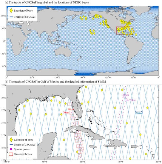
Figure 1.
(a) Tracks of CFOSAT and the locations of the NDBC buoys used in this study. (b) Tracks of CFOSAT, the locations of the NDBC buoys, the boxes for wave spectra measurement, and the mean spectra points.
With the exploitation of radio frequency scattering in the HF frequency band by Barrick [4], attempts at wave measurement based on radar began. Barrick [5] presented the first inversion method for nonlinear integral equations and the extraction of ocean wave spectra from high-frequency (HF) radar Doppler spectra, which was improved by Lipa [6]. As a tool for measuring ocean waves, HF radar has been utilized in subsequent studies [7,8]. Although radars are often mounted onboard ships, due to the high cost of ocean voyages, it is difficult and extravagant to obtain global ocean wave information using these radars.
Since the first glimpse of global ocean waves provided by Seasat in 1979, genuine global ocean wave observations have been achieved. Subsequently, Geosat provided climatological wave fields from November 1986 to January 1990 [9]. According to incomplete statistics, to date, more than 18 ocean wave monitoring satellites have been launched with altimeters onboard and have monitored global ocean waves for more than 25 years. As shown in Figure 2, currently, more than 10 satellite altimeters are still working. Early attempts to utilize altimeter SWH data by assimilating them into wave models were performed in the 1980s [10,11,12], and due to the large quantity and reliable quality of altimeter SWH data, they are still widely used in wave model assimilation [13,14,15]. Nevertheless, altimeters cannot retrieve wave spectrum information. The problems of global ocean wave spectrum observations were solved to a certain extent with the launch of the first European Remote Sensing (ERS-1) satellite in July 1991, and two-dimensional wave spectra in the global ocean were measured for the first time by synthetic aperture radar (SAR). By utilizing the wave spectra inversed by SAR, the statistics for swell features in the global ocean and the techniques for wave spectral assimilation were discussed [16,17,18]. However, in SAR instruments, wind-wave systems, whose wavelengths are typically less than 200 m, are neglected due to the wavelength cut-off; hence, the spectra retrieved by SAR are more suitable for describing swell systems [19,20,21,22,23]. Different from buoy observation, the wave spectrum estimated by SAR is in the form of wavenumber spectrum instead of frequency spectrum, the wavenumber spectrum can be converted into the frequency spectrum through the dispersion relation related to the depth of water. Since the same wavenumber corresponds to different frequencies with the variation of water depth, the wavenumber spectra estimated by different instruments can be unified to the frequency spectra through the dispersion relation. In order to indicate the range of frequency estimated by different instruments, the frequencies of wavenumber spectral bins from Sentinel-1 SAR data in the area of shallow water (10 m), moderate deep water (100 m), and deep water (1000 m) are shown as blue marks in Figure 3, while the frequencies of wave spectral bins estimated by NDBC buoy are shown as black marks.
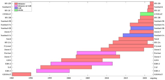
Figure 2.
Satellite launch dates and operational periods.

Figure 3.
Discrete frequency bins of wave spectra retrieved from CFOSAT and Sentinel-1 corresponding to different water depths and discrete frequency bins of buoy wave spectra.
The Chinese–French Oceanography Satellite (CFOSAT), which was launched on 29 October 2018, improved our ability to observe ocean wave spectra. The tracks of CFOSAT are shown as blue lines in Figure 1. Onboard CFOSAT, the Surface Wave Investigation and Monitoring (SWIM) instrument was designed for measuring the directional ocean wave spectra without the limitations of SAR imaging. The spectra of ocean waves in the wavelength range of 70–500 m are determined using SWIM. As a result, the spectral information of ocean waves is accessible not only under swell conditions but also in wind- wave and mixed wave conditions [24]. The discrete frequency bins of CFOSAT corresponding to different water depths are shown in Figure 3 as red marks. As the first global remote sensing product containing wind wave and mixed wave information, the accuracy is an important issue of concern. Xiang et al. [25] validated the wind and wave information during global tropical cyclones and indicated that the error of CFOSAT SWH and wind speed information increase with the enhancement of tropical cyclone intensity. Li et al. [26] validated the nadir SWH with in situ observations and enhanced the accuracy through a simple calibration. Tang et al. [27] appraised the accuracy of the SWIM product in the South China Sea by comparing with 2 buoys to validate the SWH, spectral peak period, and dominant azimuth. Although CFOSAT provides a wealth of observed wave spectra, most studies focus on the general wave parameters, and discussions on the accuracy of SWIM wave spectra are rare. Jiang et al. [28] validated the CFOSAT directional wave spectra by comparing the partitioned integrated wave parameters of SWIM wave spectra and in situ observations with cross-assignment, but due to the limitations of cross-assignment, only validations for the best-matched partitions were performed. Grigorieva et al. [29] analyzed the difference between SWIM spectral partition data and voluntary observing ship (VOS) data and indicated that none of the partitions can be confidently attributed to wind-driven waves or swells.
According to previous studies, it is still difficult to summarize a quantitative evaluation of SWIM wave spectra accuracy, which is necessary for data correction and assimilation. Thus, the intention of this study is to discuss the reliability of SWIM wave spectra and achieve a common conclusion based on the statistic results for estimating the accuracy of SWIM wave spectra while there are no in situ observations. The remainder of this article is organized as follows: the observation data and validation method are introduced in Section 2; in Section 3, analyses of SWIM wave spectra are performed; and Section 4 gives the conclusions and prospects of this study.
2. Materials and Methods
2.1. CFOSAT Data
CFOSAT flies in a sun-synchronous orbit with a low altitude of approximately 500 km and monitors the global ocean over a 13-day cycle. The highest latitude the nadir reaches is 82.56°, and the distance between adjoining tracks is 200 km. CFOSAT inverses the directional wave spectra using the SWIM wave scatterometer, which operates at 13.575 GHz and illuminates the ocean surface sequentially with 6 incidence angles: 0°, 2°, 4°, 6°, 8°, and 10°. For the 0° beam (namely, the nadir beam), the SWH is estimated in a way similar to a radar altimeter, and the measurements of the 2° and 4° beams are used only to complement the normalized radar cross section information over the full range of incidence angles but not to estimate wave spectra. The wave spectra are estimated by the 6°, 8° and 10° beams and are provided in 12 equal discrete directions from 0° to 180° and 32 unequal discrete wavenumber bins from = 0.0126 rad/m to = 0.2789 rad/m. The wave spectrum with an approximately 70 × 90 km horizontal resolution along the track is retrieved from each 70 km × 90 km wave cell (box) on each side of the nadir track as shown by the purple points and red boxes in Figure 1b. In the Level 2 products of SWIM, the wave spectra estimated by the 6°, 8°, and 10° beams and their combinations are provided. The classical watershed algorithm [30] is used for wave spectral partitioning in the SWIM product, and the mask matrices consisting of 0 and 1 used for extracted partitions are provided. Due to the difference of wave spectrum, each wave spectrum corresponds to its own mask matrices, then the partitioned wave spectrum can be extracted by the wave spectrum and the corresponding mask matrix , i.e., . As shown in Figure 4a,c,e, the shading is the energy density of wave spectrum and the parts enclosed by color lines are the different partitions.
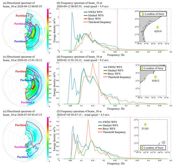
Figure 4.
Directional spectra retrieved from the 10° beam and their partitions and the corresponding frequency spectra. Subfigures (a,c,e) are the directional wave spectral patterns, and the domains enclosed by colored lines are the partitions of wave spectra provided by SWIM products. Subfigures (b,d,f) indicate the validation of the frequency spectra integrated from the left directional wave spectra. The red curves are the frequency spectra observed by buoys, the blue curves are the frequency spectra integrated from the 10° beam wave spectra without partitioning, and the green curves are the frequency spectra integrated from the three partitions of the 10° beam wave spectra, the red dash line is the frequency for separating swell and wind wave. The locations of the corresponding buoys are depicted as the yellow diamonds in the right maps, the numbers below the diamonds are the codes of the buoys.
In this study, the directional slope spectra of waves are measured by SWIM from 1 January 2020 to 31 December 2022, and the SWIM data within the 50 km × 50 km horizontal spatial window and the 1 h temporal window with buoy data are validated. The SWIM data are available at ftp://ftp-access.aviso.altimetry.fr/cfosat, last accessed on 1 July 2023.
2.2. In Situ Buoy Data
Generally, buoy observational data are considered to have the best estimation accuracy in ocean wave measurements and are usually very suitable for the validation of satellite remote sensing data. The buoy data used in this study were gathered and published by the National Data Buoy Center (NDBC), which is a public database with the largest quantity of wave buoys in the world. The information of the observed wave frequency spectrum (WFS) can be obtained directly from parts of the wave buoys. As described by the NDBC wave measurements report, the WFS are estimated by measuring the heave acceleration or the vertical displacement of the buoy hull during the wave acquisition time, followed by a fast Fourier transform (FFT). Then, response amplitude operator (RAO) processing is performed on the transformed data to account for both hull and electronic noise and derived the WFS. The buoy-observed WFS has 47 discrete frequency bins with unequal intervals from = 0.020 Hz to = 0.485 Hz. In this study, wave parameters such as significant wave height, wave direction, and the wave frequency spectra from 1 January 2020 to 31 December 2022 observed by 98 NDBC wave buoys are chosen for the validation of the CFOSAT wave spectra (WS). The statistics of the buoys and selected samples are listed in Table 1 and Table 2. For the samples, the distance to the coastline and the water depth refer to the locations of the corresponding buoys. The statistical results show that the samples of buoy data are well distributed at distances away from the coastline and at differing water depth. The validation samples selected in this study are well representative, which can cover the situations from nearshore to open ocean and from shallow water to deep water.

Table 1.
Statistics of the distance from the locations of the buoys to the coastline.

Table 2.
Statistics of the water depth at the locations of the buoys.
2.3. Validation Method
Considering that buoy data and CFOSAT data provide frequency wave spectra and directional slope spectra, respectively, the validation of wave spectra needs a preprocessing of conversion. Here, we define as the total energy of wave spectrum, then, the total energy should be the integration of frequency spectrum: , or slope spectrum . Hence, the conversion relation for translating directional slope spectrum into frequency spectrum can be established as follows:
where is the frequency spectrum, is the frequency component, is the slope spectrum, is the wavenumber component and is the direction component. The conversion relation of frequency and wavenumber is described in the dispersion relation [31]:
Here, is the gravitational constant, and is the local water depth. The ETOPO1 1-arc-min global relief model is used as the source of bathymetry information. Substituting Equation (2) into Equation (1) and considering that for each discrete frequency bin, the energy should be equal, then we can obtain the conversion from SWIM directional slope spectrum to frequency spectrum, as indicated in Equation (3)
After the process of conversion according to Equation (3), the directional slope spectra provided by SWIM can be transformed into frequency spectra, which have the same form as the buoy wave spectra data published by the NDBC. Then, the WFS of SWIM is interpolated into buoy frequency bins to ensure that they correspond to the same discrete frequency bins.
We will discuss the performance of SWIM wave spectra data in different sea states by comparing SWIM wave spectra data with the in situ buoy spectrum data. The bias, root-mean-square-error (RMSE) and standard deviation (Std) are used as the WFS accuracy evaluation indexes in the following.
Here, and are the SWIM SWH and buoy SWH, respectively. is the total number of samples, and the superscript “¯” indicates the average of and . In addition, the correlation-coefficient of spectra (Rs) between SWIM WFS and buoy WFS is used to represent the accuracy of the SWIM WFS form in this study. For each validation sample, and are the energy densities for frequency bins in SWIM WFS and buoy WFS, and is the number of frequency bins.
2.4. Filtering Method
As mentioned in Section 2.1, the mask matrices for spectral partitions can classify the wave spectra into several wave systems. In the SWIM Level 2 products, for each observed point, three mask matrices for spectral partitions with value 0 or 1 are provided. Here, we retain the spectral partitions filtered by the three mask matrices, then merge them into a new spectrum:
where the is the full wave spectrum provided by SWIM, the is the corresponding mask matrix for partition , when , it means that the spectral bin with wavenumber and direction is assigned to partition , and is the wave spectrum with mask, just as the spectrum within the all partition zones in Figure 4a–d.
As shown in Figure 4a–d, more accurate wave spectra can be achieved by the filter of mask matrices, according to the reference of buoys observation spectra, the high energy density parts near 0.05 Hz filtered by the mask can be identified as noise, and these spurious peaks are mainly due to the remaining presence of noise floor of the slope spectra. When the slope spectra are converted into frequency spectra, the noise in the low frequency will be dramatically amplified by dividing , this phenomenon has been reported in Jiang et al. [32] and Hauser et al. [33]. However, using mask matrices provided by SWIM to filter noise is not always reliable, as depicted in Figure 4e–f, the wave system near 0.05 Hz is misjudged as noise by the mask matrices and eliminated, then leads to a worse result. Therefore, it is difficult to determine the type of redundant parts without the reference of buoy observation, a general evaluation by validating the SWIM WFS with and without mask filter is necessary.
2.5. Separating Method for Wind Wave and Swell
According to Figure 4, we notice that the mask filter mainly removes the low-frequency part and high-frequency part, which is dominated by swell and wind wave, respectively. Therefore, we can discuss the impact of mask filter for wind wave spectra and swell spectra. For frequency-directional spectra, the watershed algorithm is undoubtedly an effective method for partitioning and separating wave systems, but the watershed algorithm does not class the wave systems, each wave system can be classed into wind wave or swell through other judgment. But for the frequency spectra measured by buoy, the directional component is integrated, instead, for the classification of frequency spectra, a simple method based on frequency and wind speed is performed to separate the wind wave part and the swell part [34]:
where is the partition frequency to separate wind wave and swell, is the wind speed 10 m above the sea surface. is the gravitational constant, and is the empirical coefficient. In this study, and are configured [35]. is shown as the red dash lines in Figure 4b,d,f, the part of wave spectrum with the frequency lower than is corresponding to swell, the part of spectrum with the frequency lower than is corresponding to wind wave.
3. CFOSAT WS Validation
3.1. Error Analysis in Frequency Component
Figure 5 and Table 3 show the results of validation. Wave spectra retrieved from the 6°, 8°, and 10° beams and their combination are validated. The bias, RMS and Std of SWH are computed to indicate the accuracy of the SWIM WFS in total energy. The mean R of the WFS (i.e., Rs in Figure 5) is computed by averaging all Rs and is used to indicate the accuracy of the SWIM WFS in spectral form. Under the evaluation indexes, a lower RMS means a more consistent total energy between the SWIM WFS and buoy WFS, a higher Rs means a closer form between the SWIM WFS and buoy WFS. The bold text in Table 3 highlights the highest accuracy for each evaluation index. The results show that for different incidence beams, the accuracy of SWH is similar, the RMS of SWH is 0.23 m, it is mainly cause by the operational processing that normalizing the energy of the wave spectrum by the SWH obtained from the nadir beam [36]. The beam with greater incidence angle represents the higher value of Rs, the combination spectra only achieve the balance of Rs between three beams, but do not provide the best measurement, the RMS of SWH is 0.33 m. The filtering of mask leads to a higher value of Rs and RMS, which indicates that the mask filter removes some energy information then cause a negative bias of total energy, but improves the accuracy of spectral form in general. The wave spectra estimated by the 10° beam without mask filter have the best accuracy in total energy, and the wave spectra estimated by the 10° beam with mask filter have the best similarity in form.
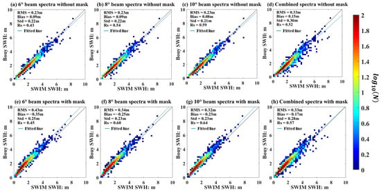
Figure 5.
Validation of the WFS retrieved from different beams. (a–d) correspond to the WFS obtained from different beams without mask filter, and (e–h) correspond to the WFS obtained from different beams with mask filter.

Table 3.
Validation of the spectra retrieved from different beams (the bold text highlights the highest accuracy for each evaluation index).
In order to gain a better understanding for the meaning of Rs, we selected the high Rs spectra and low Rs spectra for plotting. Figure 6 indicates the SWIM spectra and their corresponding buoy spectra with high Rs (Rs > 0.8), Figure 7 indicates the SWIM spectra and their corresponding buoy spectra with low Rs (Rs < 0.4). It is obvious that for high Rs, the SWIM spectra are similar to the buoy spectra, although there are some differences in amplitude. For low Rs, there is a significant difference between the SWIM spectra and the buoy spectra, and the low-frequency noise is more significant.
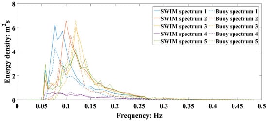
Figure 6.
SWIM spectra and their corresponding buoy spectrum with the Rs higher than 0.8.
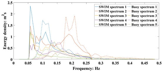
Figure 7.
SWIM spectra and their corresponding buoy spectrum with the Rs higher than 0.4.
Now we can focus on the WFS of the wind wave and the swell from the full WFS. For the wind wave part, as shown in Figure 8 and Table 4, the WFS from different incidence angle beams represent different accuracy, the greater incidence angle beam represents the higher accuracy, the mask filter leads to a further negative bias and a lower value of Rs. For the swell part, as shown in Figure 9 and Table 5, similar to wind wave WFS, the greater incidence angle beam represents the higher accuracy, the positive bias is reduced and the Rs is improved by the mask filter. These results indicate that the noise in low frequencies is the main reason for the error of swell, it leads an over estimation of swell energy then causes the positive bias and poor spectral form. Thus, the accuracy of WFS can be improved through the mask filter. However, for the wind wave part, the accurate spectra can have been estimated without the influence of low frequency noise; thus, the mask filter would remove the information of wind wave spectra, leading to worse results, such as the wind wave part shown in Figure 4d.
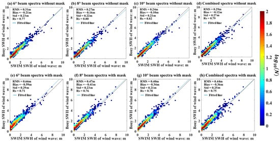
Figure 8.
Validation of the WFS (wind wave part) retrieved from different beams. (a–d) correspond to the WFS of wind wave part obtained from different beams without mask filter, and (e–h) correspond to the WFS of wind wave part obtained from different beams with mask filter.

Table 4.
Validation of the wind wave spectra retrieved from different beams (the bold text highlights the highest accuracy for each evaluation index).
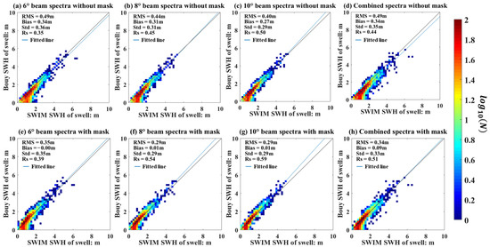
Figure 9.
Validation of the WFS (swell part) retrieved from different beams. (a–d) correspond to the WFS of swell part obtained from different beams without mask filter, and (e–h) correspond to the WFS of swell part obtained from different beams with mask filter.

Table 5.
Validation of the swell spectra retrieved from different beams (the bold text highlights the highest accuracy for each evaluation index).
According to these results and analyses, we can conclude that the low frequency noise is exist commonly in swell part and leads the poor swell spectra, the correction through the mask filter can reduce the positive bias of swell SWH from 0.3 m to 0 m, and improve the accuracy of swell spectral form, oppositely, for the wind wave part, the mask filter may lead to a worse wind wave spectrum.
3.2. Factors That Impact the WS Accuracy
In this section, we clarify which factors will have a clear correlation with the accuracy of spectral form, so the Rs for each sample will be discussed.
First, we discuss the relation between the wind speed and Rs. As the statistics in Figure 10, for all samples, most of the wind speeds are less than 15 m/s, and 58% of the wind speeds are greater than 3 m/s and less than 9 m/s. The scatter distribution shows extremely scattered when the wind speed is less than 10 m/s, so it is hard to estimate the Rs based on wind speed. Due to the cutoff frequency of the SWIM wave spectrum, the wind wave spectrum can be retrieved only when the wind speed is higher than 6 m/s, although the Rs of wind wave is higher than 0.5 in general, the value of Rs does not vary significantly with the wind speed (Figure 11). For the swell part, in terms of physical mechanism, the swell no longer gains the momentum and energy brought by wind; thus, there is no direct relationship between the swell spectrum and local wind.
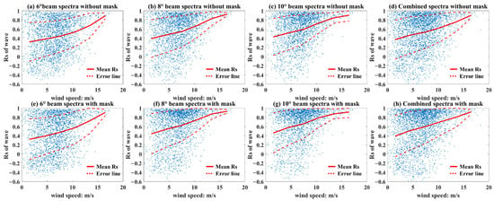
Figure 10.
Scatter of the wind speed and Rs of wave. The red line is the mean R for per 3 m/s width wind speed window, the red dash lines are the error lines with ±Std.
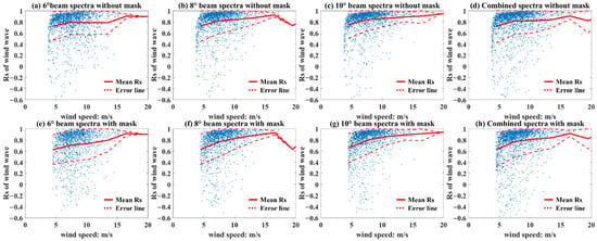
Figure 11.
Scatter of the wind speed and Rs of wind wave. The red line is the mean Rs for per 3 m/s width wind speed window, the red dash lines are the error lines with ±Std.
Now, we discuss the impact of geographical location on the SWIM wave spectra estimation. Generally, wave systems in the open ocean are relatively simple; in contrast, near-shore wave systems are complex with the impact of refraction and reflection. The relations between the SWH, distance to coastline, and the Rs are shown in Figure 12. It is not hard to find that the Rs increases with the increasement of SWH and but varies slightly with the distance to the coastline, i.e., the accuracy of SWH is independent of the observation region and relatively stable, while the accuracy of spectral form is related to SWH. when the SWH is higher than 2 m, Rs shows a high value. Figure 13 and Figure 14 show the relationship between the Rs of wind wave and swell with the varies of the SWH and the distance to the coastline, which also confirms the point that the Rs of wave has a significant correlation with the SWH, but a weak correlation with geographical location.
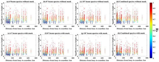
Figure 12.
Relation between the SWH, Rs, and the geographical location, the colors of the dots represent the Rs. (a–d) correspond to the WFS obtained from different beams without mask matrices filtering, and (e–h) correspond to the WFS obtained from different beams with mask matrices filtering.
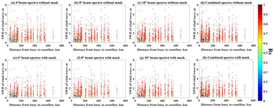
Figure 13.
Relation between the SWH of wind wave, Rs of wind wave, and the geographical location, the colors of the dots represent the Rs. (a–d) correspond to the WFS obtained from different beams without mask matrices filtering, and (e–h) correspond to the WFS obtained from different beams with mask matrices filtering.
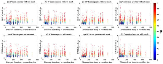
Figure 14.
Relation between the SWH, Rs of swell, and the geographical location, the colors of the dots represent the Rs. (a–d) correspond to the WFS obtained from different beams without mask matrices filtering, and (e–h) correspond to the WFS obtained from different beams with mask matrices filtering.
Figure 15, Figure 16, Figure 17 and Figure 18 indicate the distribution characteristics of the Rs and the SWH, the red solid lines are the mean Rs for per 1 m width SWH window, these results prove that the value of Rs is a monotone increasing function of SWH statistically. For the whole wave (Figure 15), the value of Rs increases to 0.8 when the SWH increases to 3 m, after the filtering of mask, the value of Rs can reach 0.8 when the SWH is 2 m. However, for the wind wave, the mask filter does not lead a significant improvement for the value of Rs. For the swell, the value of Rs increases to 0.8 sharply after the filtering of the mask.
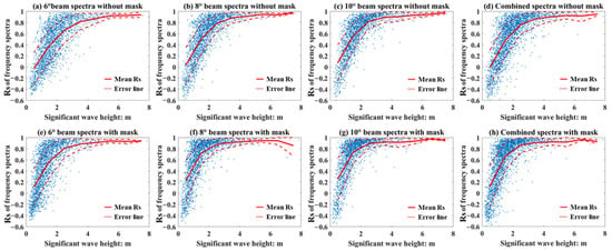
Figure 15.
Relation between the SWH and the Rs, the red solid lines are the mean Rs for per 1 m width SWH window, the red dash lines are the error lines with ±Std. (a–d) correspond to the WFS obtained from different beams without mask matrices filtering, and (e–h) correspond to the WFS obtained from different beams with mask matrices filtering.
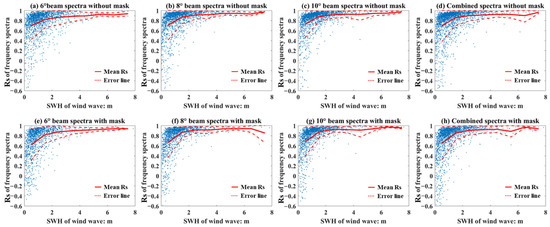
Figure 16.
Relation between the SWH of wind wave and the Rs of wind wave, the red solid lines are the mean Rs for per 1 m width SWH window, the red dash lines are the error lines with ±Std. (a–d) correspond to the WFS obtained from different beams without mask matrices filtering, and (e–h) correspond to the WFS obtained from different beams with mask matrices filtering.
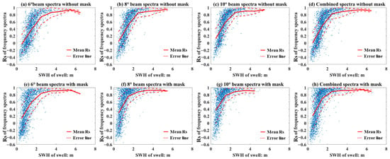
Figure 17.
Relation between the SWH of swell and the Rs of swell, the red solid lines are the mean Rs for per 1 m width SWH window, the red dash lines are the error lines with ±Std. (a–d) correspond to the WFS obtained from different beams without mask matrices filtering, and (e–h) correspond to the WFS obtained from different beams with mask matrices filtering.

Figure 18.
Relation between the SWH and the mean Rs, the solid lines are the mean Rs without mask filter for per 1 m width SWH window, the dash lines with triangle markers are the mean Rs with mask filter for per 1 m width SWH window.
Figure 19 shows the relation of the SWH and the mean Rs for the whole wave, wind wave part, and swell part. the solid lines are the mean Rs without mask filter and the dash lines with triangle markers are the mean Rs with mask filter. It proves that the improvement of Rs by mask filter is mainly caused by the filtering of low frequency noise in the swell part, and the influence of mask filter in the wind wave part is slight.
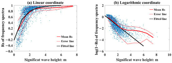
Figure 19.
Relation between the Rs and SWH in different coordinate systems. The red solid lines are the mean value of the R for per 1 m width SWH window, the red dash lines are the error lines with ±Std, and the black lines are the fitting function established by Equation (11).
According to the results, although the value of Rs is a monotone increasing function of SWH statistically, for different beams, the functions are different. Therefore, we need to select a series of representative WFS as the basis for analyzing the functional relationship of Rs and SWH. As results in Table 4, the 10° beam WFS without the mask filter has the best SWH estimation, and the 10° beam WFS with the mask filter provides the WFS with the best spectral form. It means that the best WFS with both total energy (i.e., the SWH) and spectral form can be obtained as follows:
where is the 10° beam WFS with the mask, is the 10° beam WFS without the mask, and is the frequency of the wave spectra. The purpose of this formula is to maintain the form of the 10° beam WFS with the mask to have the highest accuracy in spectral form but adjust the total energy to be consistent with the 10° beam WFS without the mask filter to have the best accuracy in total energy, and the best WFS are used for analyzing the functional relationship of Rs and SWH.
Figure 19 shows the relation between the Rs and SWH calculated from the best WFS . In the linear coordinate system (Figure 19a), there is a good corresponding relation between the R and SWH, which presents a monotonic tendency: R increases with increasing SWH. In the logarithmic coordinate system, a strong linear characteristic between log(1-R) and SWH can be found. Based on the distribution of the SWH and R in the logarithmic coordinate system, it is easy to use linear fitting to establish the empirical relation:
The red lines in Figure 19 reflect the mean value of the Rs, and the black lines is the value of Rs computed using Equation (11). When the SWH is lower than 3 m, Equation (11) can fit well with different SWH situations, and when the SWH is higher than 3 m, the mean Rs is higher than 0.9, we can ensure that accurate WFS can be obtained; thus, there is no need to perform a quality estimation through Equation (11).
In general, the Rs represents the accuracy of SWIM estimated spectra in form, it is a comprehensive indicator to indicate the accuracy for the distribution of energy density in spectra, the location of spectral peak, the characteristics of wind wave and swell, and so on. The higher value of R means stronger linear relationship between SWIM WFS and the true WFS, thus, it is easy to correct the whole energy of WFS then obtain a more accurate WFS through the other accurate SWH observation, i.e.,:
where is the more accurate WFS, is the estimated WFS, is the accurate value of SWH and is the value of SWH corresponding to the estimated WFS .
Figure 20 shows the distribution of the annual mean Rs, which is higher than 0.7 in the open ocean, and the highest value occurs in the westerlies with Rs higher than 0.8, it is easy to obtain an accurate WFS according to SWIM and other reliable SWH observations in these regions. While in regions with complex terrain, such as Southeast Asia, the R value is basically lower than 0.3. the Rs is basically lower than 0.3, it indicates that the distributions of energy density in SWIM WFS are incorrect. The empirical relation between SWH and Rs provides the reliability of spectral form measured by CFOSAT in any region, which is important in wave spectral data assimilation.
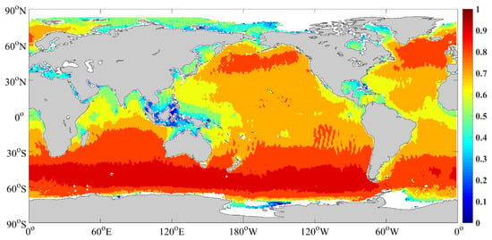
Figure 20.
Global Rs of the best WFS estimated by the empirical formula.
Generally, although CFOSAT provides global observations of ocean wave spectra, limited by the low accuracy of the spectral form in the nearshore, in situ observations of wave spectra still need to be supplemented. The SWH rather than the wave spectrum is recommended if it is necessary to use CFOSAT wave spectra data for research such as analysis of energy characteristic, swell propagation, and data assimilation in the nearshore.
3.3. Error Analysis in Directional Component
In this section we discuss the accuracy of SWIM wave spectra (WS) in directional component. Due to the exist of 180° ambiguity in SWIM WS, other parameters that can indicate the direction of ocean waves need to be used as a reference. Here, we choose the peak direction (PD) parameter calculated by SWIM operational processor as a reference for eliminating 180° ambiguity. Firstly, we validate the accuracy of the PD provided by SWIM by comparing with buoy observation data. As shown in Figure 21, PD bias for most of the samples are distributed around 0° and ±180°, it means that although the PD provided by SWIM with a range of 0–360°, the reference value of them is extremely limited, and the 180° ambiguity has not been eliminated. Here, we make a further correction for the PD base on wind direction with the supposition that the angle between wind direction and wave direction is within 90°, i.e., if , then , is the wind direction. The SWIM product does not provide the wind information; therefore, the wind direction observed by buoy is used for correction. The results are shown in Figure 22, there is not a significant improvement for the 180° ambiguity.

Figure 21.
Relation between the SWH and the bias of peak direction obtained from different beams, the red solid lines are the mean the bias of peak direction for per 1 m width SWH window, the red dash lines are the error lines with ±Std.

Figure 22.
Relation between the SWH and the bias of peak direction obtained from different beams corrected by wind direction, the red solid lines are the mean the bias of peak direction for per 1 m width SWH window, the red dash lines are the error lines with ±Std.
The 180° ambiguity is a common problem in remote sensing and can be solved to some extent through a series of technologies. Here, we would like to know the accuracy of WS without 180° ambiguity, we eliminate 180° ambiguity in a simple and effective way: if , then , so that we can analyze the relationship between the SWH and the PD error ideally. As shown in Figure 23, the bias for the PD of WS is dispersed while the SWH is lower than 2 m, and the mask filter produce very little effect. Figure 24 shows the relation between the wind speed and the bias of PD (without 180° ambiguity) and indicates that there is no correlation between the bias of PD and wind speed. Similar to Rs, there is no correlation between the bias of PD and geographical location, as shown in Figure 25 and Figure 26.
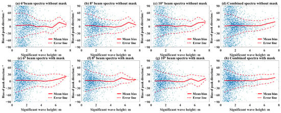
Figure 23.
Relation between the SWH and the bias of PD (without 180° ambiguity), the red solid lines are the mean the bias of PD for per 1 m width SWH window, the red dash lines are the error lines with ±Std. (a–d) correspond to the WS obtained from different beams without mask matrices filtering, and (e–h) correspond to the WS obtained from different beams with mask matrices filtering.
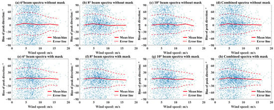
Figure 24.
Relation between the wind speed and the bias of PD (without 180° ambiguity), the red solid lines are the mean bias of PD for per 3 m/s width wind speed window, the red dash lines are the error lines with ±Std. (a–d) correspond to the WS obtained from different beams without mask matrices filtering, and (e–h) correspond to the WS obtained from different beams with mask matrices filtering.
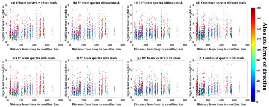
Figure 25.
Relation between the wind speed, bias of PD (with 180° ambiguity), and the geographical location, (a–d) correspond to the WS obtained from different beams without mask matrices filtering, and (e–h) correspond to the WS obtained from different beams with mask matrices filtering.
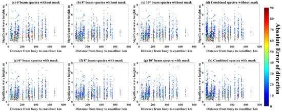
Figure 26.
Relation between the wind speed, bias of PD (without 180° ambiguity), and the geographical location, (a–d) correspond to the WS obtained from different beams without mask matrices filtering, and (e–h) correspond to the WS obtained from different beams with mask matrices filtering.
4. Conclusions
Since the launch of CFOSAT on 29 October 2018, more than three years of observation data of ocean wave spectra have been obtained. The ocean wave research community is generally concerned about the observation accuracy of ocean wave spectra. Therefore, in this study, we validated the CFOSAT wave spectra (WS) estimated by different beams compared with the corresponding 98 in situ buoy data provided by the NDBC from 1 January 2020 to 31 December 2022. This work has an important reference role for global wave data assimilation and the use of the CFOSAT wave spectrum and lays a foundation for further improvements of the two-dimensional wave spectrum. The results indicate the following:
(1) The wave spectra provided by different beams have different accuracies in both total energy and spectral form. The 10° beam wave spectra without mask filtering provide the best estimation of the SWH (RMS = 0.23 m), but the R of these spectra (Rs) is relatively low (R = 0.59). The 10° beam wave spectra with mask filtering provide the best description of the spectral form (R = 0.64), but the estimation of the SWH is relatively poor (RMS = 0.32 m).
(2) The existence of low-frequency noises is the main factor that makes the SWIM WFS unreliable, especially in swell part, and the improvement of Rs through the filtering of mask mainly due to the correction of swell WFS; however, for the wind wave WFS, accurate WFS has been achieved and the mask filter would lead to a worse WFS for the wind wave part.
(3) The value of Rs is not related to the wind speed and the distance from the observation location to the coastline, but is significantly related to the SWH, an empirical formula in exponential form can be easily fitted: .
(4) Based on this formula, the Rs can be estimated in the global ocean even if there is no in situ data for validation. The results indicate that the CFOSAT WS are accurate in the open ocean, where the Rs is higher than 0.7. However, in the regions with complex terrain, such as Southeast Asia, the estimated spectra are low qualities. The SWH, rather than the wave spectrum, is recommended for reference.
(5) Although the peak direction (PD) of wave with the range from 0–360° is provided as the wave parameter in SWIM, 180° ambiguity has not been well resolved. According to the validation results for the bias of PD, the bias is mainly concentrated at 0° and ±180°, which means that the 180° ambiguity even exist in the PD provided by SWIM wave parameters. Ignoring the problem of 180° ambiguity by folding the sea wave spectrum, the accuracy of WS in directional component is poor performance, and is not related to wind speed, geographical location, and SWH.
In summary, CFOSAT provides a reliable estimation of SWH in the global ocean, and the estimation of wave spectra is reliable when the SWH is higher than 2 m. Through the statistics of the validation results, a simple but robust relationship between the accuracy of Rs and SWH was found in this study, the value of Rs can be estimated by the SWIM SWH in global oceans. However, the CFOSAT wave spectral data do not perform well in indicating wave directions. This study is not only an evaluation of the quality of the CFOSAT spectral data, but also an important reference for a series of research requiring the CFOSAT spectral data, such as the analysis of global wave characteristics, the analysis of wave propagation process, data assimilation, etc.
Author Contributions
Conceptualization, S.L. (Songlin Li) and H.Y.; methodology, S.L. (Songlin Li) and H.Y.; software, S.L. (Songlin Li) and J.Y.; validation, S.L. (Songlin Li); formal analysis, S.L. (Songlin Li) and H.Y.; investigation, X.Y.; resources, X.Y.; data curation, S.L. (Shuyan Lang); writing—original draft preparation, S.L. (Songlin Li); writing—review and editing, H.Y.; visualization, S.L. (Songlin Li); supervision, H.Y.; project administration, K.W.; funding acquisition, H.Y. All authors have read and agreed to the published version of the manuscript.
Funding
This research was funded by the National Key Research and Development Program of China (grant number 2022YFD2401304) and the Project of Sanya Yazhou Bay Science and Technology City (grant number SCKJ-JYRC-2022-101, SKJC-2022-01-001).
Data Availability Statement
The buoy observing wave frequency spectral data are available from National Data Buoy Center (NDBC, <https://www.ndbc.noaa.gov/> [last accessed on 1 July 2023]), the CFOSAT remote sens-ing wave spectral data are available from Archiving, Validation and Interpretation of Oceano-graphic Satellite Data (AVISO, <https://www.aviso.altimetry.fr/en/home.html> [last accessed on 1 July 2023]) and National Satellite Ocean Application Service (NSOAS, <http://www.nsoas.org.cn/> [last accessed on 1 July 2023]), all data used for analysis in this paper are sourced from these public datasets, no new data were created.
Acknowledgments
The buoy observing wave frequency spectral data are available from National Data Buoy Center (NDBC), the CFOSAT remote sensing wave spectral data are available from Archiving, Validation and Interpretation of Oceano-graphic Satellite Data (AVISO) and National Satellite Ocean Application Service (NSOAS). The authors would like to thank these institutions for their data support. Also, the authors would like to thank Christine Cheng, Lavender Zhao, and anonymous reviewers for their constructive suggestions.
Conflicts of Interest
The authors declare no conflict of interest.
References
- Ardhuin, F.; Marié, L.; Rascle, N.; Forget, P.; Roland, A. Observation and estimation of Lagrangian, Stokes, and Eulerian currents induced by wind and waves at the sea surface. J. Phys. Oceanogr. 2009, 39, 2820–2838. [Google Scholar] [CrossRef]
- Hsiao, S.C.; Chen, H.; Chen, W.B.; Chang, C.H.; Lin, L.Y. Quantifying the contribution of nonlinear interactions to storm tide simulations during a super typhoon event. Ocean Eng. 2019, 194, 10661. [Google Scholar] [CrossRef]
- Chang, T.Y.; Chen, H.; Hsiao, S.C.; Wu, H.L.; Chen, W.B. Numerical analysis of the effect of binary typhoons on ocean surface waves in waters surrounding Taiwan. Front. Mar. Sci. 2021, 8, 749185. [Google Scholar] [CrossRef]
- Barrick, D.E. Remote sensing of sea state by radar. In Remote Sensing of the Troposphere; Derr, V.E., Ed.; NOAA/Environmental Research Laboratories: Newport, RI, USA, 1972; pp. 186–192. [Google Scholar]
- Barrick, D.E. Extraction of wave parameters from measured HF radar sea-echo Doppler spectra. Radio Sci. 1977, 12, 415–424. [Google Scholar] [CrossRef]
- Lipa, B.J. Derivation of directional ocean-wave spectra by integral inversion of second-order radar echoes. Radio Sci. 1977, 12, 425–434. [Google Scholar] [CrossRef]
- Borge, J.C.N.; Reichert, K.; Dittmer, J. Use of nautical radar as a wave monitoring instrument. Coast. Eng. 1999, 37, 331–342. [Google Scholar] [CrossRef]
- Huang, W.M.; Wu, S.C.; Gill, E. HF radar wave and wind measurement over the Eastern China Sea. IEEE T. Geosci. Remote Sens. 2002, 40, 1950–1955. [Google Scholar] [CrossRef]
- Foreman, S.J.; Holt, M.W.; Kelsall, S. Preliminary Assessment and Use of ERS-1 Altimeter Wave Data. J. Atmos. Ocean. Tech. 1994, 11, 1370–1380. [Google Scholar] [CrossRef]
- Komen, G.J. Introduction to Wave Models and Assimilation of Satellite Data in Wave Models; European Space Agency Publications: Paris, France, 1985; Volume SP-244, pp. 21–26. [Google Scholar]
- Thomas, J.P. Retrieval of energy spectra from measured data for assimilation into a wave model. Q. J. R. Meteorol. Soc. 1988, 114, 781–800. [Google Scholar] [CrossRef]
- Esteva, D. Evaluation of preliminary experiments assimilating Seasat significant wave height into a spectral wave model. J. Geophys. Res. 1988, 93, 14099–14105. [Google Scholar] [CrossRef]
- Greenslade, D.J.M. The assimilation of ERS-2 significant wave height data in the Australian region. J. Marine. Syst. 2001, 28, 141–160. [Google Scholar] [CrossRef]
- Qi, P.; Fan, X.M. The impact of assimilation of altimeter wave data on wave forecast model in the north Indian Ocean. Marine Forecasts. 2013, 30, 70–78. [Google Scholar]
- Yu, H.M.; Li, J.Y.; Wu, K.J.; Wang, Z.F.; Yu, H.Q.; Zhang, S.Q.; Hou, Y.J.; Ryan, M.K. A global high-resolution ocean wave model improved by assimilating the satellite altimeter significant wave height. Int. J. Appl. Earth. Obs. 2018, 70, 43–50. [Google Scholar] [CrossRef]
- Hasselmann, S.; Lionello, P.; Hasselmann, K. An optimal interpolation scheme for the assimilation of spectral wave data. J. Geophys. Res. 1997, 102, 15823–15836. [Google Scholar] [CrossRef]
- Heimbach, P.; Hasselmann, S.; Hasselmann, K. Statistical analysis and intercomparison of WAM model data with global ERS-1 SAR wave mode spectral. J. Geophys. Res. 1998, 103, 7931–7977. [Google Scholar] [CrossRef]
- Sun, M.; Yang, Y.Z.; Yin, X.Q.; Du, J.T. Data assimilation of ocean surface waves using Sentinel-1 SAR during typhoon Malakas. Int. J. Appl. Earth. Obs. 2018, 70, 35–42. [Google Scholar] [CrossRef]
- Hasselmann, K.; Hasselmann, S. On the nonlinear mapping of an ocean wave spectrum into a synthetic aperture radar image spectrum and its inversion. J. Geophys. Res. 1991, 96, 10713–10729. [Google Scholar] [CrossRef]
- Yang, J.S.; Wang, H.; Huang, W.G.; Xiao, Q.M. Error analysis of Envisat ASAR level 2 algorithm based on simulation technique. In Proceedings of the 2007 IEEE International Geoscience and Remote Sensing Symposium, Barcelona, Spain, 23–28 July 2007. [Google Scholar] [CrossRef]
- Sun, J.; Kawamura, H. Retrieval of surface wave parameters from SAR images and their validation in the coastal seas around Japan. J. Oceanogr. 2009, 65, 567–577. [Google Scholar] [CrossRef]
- Mouche, A.; Chapron, B.; Johnsen, H.; Collard, F.; Wang, H.; Guitton, G.; Yang, J.; Husson, R. Perspectives for combining and exploiting ocean wave spectra measured from different space missions. In Proceedings of the 2016 IEEE International Geoscience and Remote Sensing Symposium (IGARSS), Beijing, China, 10–15 July 2016. [Google Scholar] [CrossRef]
- Aouf, L.; Hauser, D.; Tison, C.; Mouche, A. Perspectives for directional spectra assimilation: Results from a study based on joint assimilation of CFOSAT synthetic wave spectra and observed SAR spectra from Sentinel-1A. In Proceedings of the 2016 IEEE International Geoscience and Remote Sensing Symposium (IGARSS), Beijing, China, 10–15 July 2016. [Google Scholar] [CrossRef]
- Hauser, D.; Tison, C.; Amiot, T.; Delaye, L.; Corcoral, N.; Castillan, P. SWIM: The first spaceborne wave scatterometer. IEEE T. Geosci. Remote Sens. 2017, 55, 3000–3013. [Google Scholar] [CrossRef]
- Xiang, K.S.; Yin, X.B.; Xing, S.G.; Kong, F.P.; Li, Y.; Lang, S.Y.; Gao, Z.Y. Preliminary estimate of CFOSAT satellite products in tropical cyclones. IEEE Trans. Geosci. Remote Sens. 2021, 60, 1–16. [Google Scholar] [CrossRef]
- Li, X.Z.; Xu, Y.; Liu, B.C.; Lin, W.M.; He, Y.J.; Liu, J.Q. Validation and calibration of nadir SWH products from CFOSAT and HY-2B with satellites and in situ observations. J. Geophys. Res. 2021, 126, e2020JC01668. [Google Scholar] [CrossRef]
- Tang, S.L.; Chu, X.Q.; Jia, Y.J.; Li, J.M.; Liu, Y.T.; Chen, Q.; Li, B.; Liu, J.L.; Chen, W.Y. An appraisal of CFOSAT wave spectrometer products in the South China Sea. Earth. Space. Sci. 2022, 9, e2021EA002055. [Google Scholar] [CrossRef]
- Jiang, H.Y.; Mironov, A.; Ren, L.; Babanin, A.V.; Wang, J.K.; Mu, L. Validation of wave spectral partitions from SWIM instrument on-board CFOSAT against in situ data. IEEE Trans. Geosci. Remote Sens. 2021, 60, 1–13. [Google Scholar] [CrossRef]
- Grigorieva, V.G.; Badulin, S.I.; Gulev, S.K. Global validation of SWIM/CFOSAT wind waves against Voluntary Observing Ship data. Earth. Space. Sci. 2022, 9, e2021EA002008. [Google Scholar] [CrossRef]
- Hanson, J.L.; Phillips, O.M. Automated analysis of ocean surface directional wave spectra. J. Atmos. Ocean. Technol. 2001, 18, 277–293. [Google Scholar] [CrossRef]
- Mei, C.C. The Applied Dynamics of Ocean Surface Waves; Wiley: New York, NY, USA, 1983; p. 740. [Google Scholar]
- Jiang, H.Y.; Song, Y.H.; Mironov, A.; Yang, Z.; Xu, Y.; Liu, J.Q. Accurate mean wave period from SWIM instrument on-board CFOSAT. Remote Sens. Environ. 2022, 280, 113149. [Google Scholar] [CrossRef]
- Hauser, D.; Tourain, C.; Hermozo, L.; Alraddawi, D.; Aouf, L.; Chapron, B.; Dalphinet, A.; Delaye, L.; Dalila, M.; Dormy, E. New observations from the SWIM radar on-board CFOSAT: Instrument validation and ocean wave measurement assessment. IEEE Trans. Geosci. Remote Sens. 2021, 59, 5–26. [Google Scholar] [CrossRef]
- Earle, M.D. Development of algorithms for separation of sea and swell. Natl. Data Buoy Cent. Tech Rep MEC-87-1 Hancock County. 1984, 53, 1–53. [Google Scholar]
- Li, S.Q.; Zhao, D.L. Comparison of spectral partitioning techniques for wind wave and swell. Mar. Sci. Bull. 2012, 14, 24–36. [Google Scholar]
- Tourain, C.; Hauser, D.; Alraddawi, D.; Hermozo, L.; Suquet, R.R.; Schippers, P.; Aouf, L.; Dalphinet, A.; Dufour, C.; Lachiver, J.-M.; et al. Evolutions and Improvements in CFOSAT SWIM Products. In Proceedings of the 2021 IEEE International Geoscience and Remote Sensing Symposium IGARSS, Brussels, Belgium, 11–16 July 2021; pp. 7386–7389. [Google Scholar]
Disclaimer/Publisher’s Note: The statements, opinions and data contained in all publications are solely those of the individual author(s) and contributor(s) and not of MDPI and/or the editor(s). MDPI and/or the editor(s) disclaim responsibility for any injury to people or property resulting from any ideas, methods, instructions or products referred to in the content. |
© 2023 by the authors. Licensee MDPI, Basel, Switzerland. This article is an open access article distributed under the terms and conditions of the Creative Commons Attribution (CC BY) license (https://creativecommons.org/licenses/by/4.0/).