Abstract
Coastal erosion due to extreme events can cause significant damage to coastal communities and deplete beaches. Post-storm beach recovery is a crucial natural process that rebuilds coastal morphology and reintroduces eroded sediment to the subaerial beach. However, monitoring the beach recovery, which occurs at various spatiotemporal scales, presents a significant challenge. This is due to, firstly, the complex interplay between factors such as storm-induced erosion, sediment availability, local topography, and wave and wind-driven sand transport; secondly, the complex morphology of coastal areas, where water, sand, debris and vegetation co-exists dynamically; and, finally, the challenging weather conditions affecting the long-term small-scale data acquisition needed to monitor the recovery process. This complexity hinders our understanding and effective management of coastal vulnerability and resilience. In this study, we apply Convolutional Neural Networks (CNN)-based semantic segmentation to high-resolution complex beach imagery. This model efficiently distinguishes between various features indicative of coastal processes, including sand texture, water content, debris, and vegetation with a mean precision of 95.1% and mean Intersection of Union (IOU) of 86.7%. Furthermore, we propose a new method to quantify false positives and negatives that allows a reliable estimation of the model’s uncertainty in the absence of a ground truth to validate the model predictions. This method is particularly effective in scenarios where the boundaries between classes are not clearly defined. We also discuss how to identify blurry beach images in advance of semantic segmentation prediction, as our model is less effective at predicting this type of image. By examining how different beach regions evolve over time through time series analysis, we discovered that rare events of wind-driven (aeolian) sand transport seem to play a crucial role in promoting the vertical growth of beaches and thus driving the beach recovery process.
1. Introduction
Beach recovery involves the restoration of eroded sediment to the shoreline and the reconstruction of subaerial features, such as berms and dunes, following high-energy events [1]. The beach serves as a natural buffer that protects communities and ecological habitats along the shore [2]. Thus, understanding the recovery process is crucial for coastal engineers and authorities to design and manage beaches [3] and estimate the risk associated with climate change and storm clustering [4].
Comprehending the recovery of the beach to its pre-storm condition, however, is a challenging task due to the complex interplay of various factors. These factors include the magnitude of storm-induced erosion, sediment availability, and local topography, as well as wave and wind processes that occur at different temporal and spatial scales. The interaction of these processes complicates the beach recovery process, making it difficult to understand the occurrence and dynamics of beach recovery [5].
Recent developments in optical recording equipment and data storage devices have resulted in an increase in field observation data, shedding new light on beach recovery processes. For instance, an investigation of sand bar morphological responses after a storm through the use of Argus video images has shown that wave conditions play a significant role in controlling bar dynamics [6]. In a similar line of research, video observation studies have revealed the seasonality of post-storm recovery processes in sandbars and shorelines [7]. However, it is important to note the limitations of these studies. The need for manual classification or digitization of Timex images introduces the potential for human errors and inconsistencies, besides being time consuming.
Meanwhile, empirical models have become more complex as data volumes increase, making it difficult to identify which parameters are relevant and hindering their general applicability. This calls for a complementary approach to empirically based coastal modeling (top-down approach), such as pattern recognition (bottom-up approach) based on Machine Learning (ML).
The recent surge in processing capacity and methodological advancements in Machine Learning has led to the deep learning renaissance, nurturing the field of computer vision studies. Deep Convolutional Neural Networks (DCNNs) were initially introduced for image classification [8] and have proven useful in addressing several coastal science problems, such as wave breaking classification [9,10] and automatic beach state recognition [11,12]. However, to holistically analyze the beach recovery process, spatial information is necessary in addition to semantic understanding. This necessitates the implementation of image segmentation techniques, which can localize different objects and boundaries within images.
Image segmentation, the technique of partitioning a digital image into different subsets of image segments, has greatly improved accuracy in image processing tasks due to the development of convolutional neural networks (CNNs). The original study for pixel-level classification based on fully convolutional networks (FCN) [13] served as a basis for CNN-based image segmentation. In the context of coastal monitoring, CNNs also have proven to be a powerful tool for a variety of segmentation tasks. They have been leveraged to investigate coastal wetlands using imagery captured by Unmanned Aerial Systems (UAS) [14], employed to monitor Seagrass Meadows [15], and utilized to detect coastlines [16], both using remote sensing data. Recent work also highlights measuring the agreement in image labeling for coastal studies [17], which is crucial for training precise CNN-based image segmentation models. Also, an extensive labeled dataset for aerial and remote sensing coastal imagery has been created [18], supporting detailed segmentation and analysis in this field.
Notably, these studies primarily center on aerial and remote sensing imagery. When the focus shifts to close-range beach imagery for morphodynamic studies, we encounter a new set of challenges. The unique characteristics of close-range beach topography—different types of sand layers with no apparent boundaries between interfaces, uncertainty related to spatial resolution due to photogrammetric distortion, and observational vulnerability to adverse weather and lighting conditions—make it challenging to apply the algorithm to analyze short-range beach imagery for morphodynamic studies. Consequently, there is a research gap in the application of CNN-based image segmentation to monitor changes in beach morphology, particularly through close-range imagery analysis.
This paper represents the first attempt to monitor beach recovery with high temporal resolution imagery using CNN-based image segmentation, thereby addressing this research gap in the application of machine learning in coastal studies. We present customized methodologies for CNN training and beach imagery prediction and introduce a novel metric to gauge potential uncertainty in the absence of ground truth, a scenario often arising in coastal monitoring due to image quality issues. Further, we illuminate instances of false prediction and propose strategies to identify certain types of images prior to segmentation. By analyzing time series from stacked area fractions over the observation period, we look at the underlying mechanisms driving beach recovery.
2. Material and Methods
2.1. Dataset Acquisition and Annotation
We obtained images for training and validating the CNN from three solar-powered stationary GoPro cameras installed in Cedar Lakes, Texas (28.819°N, 95.519°W), which monitored beach recovery following Hurricane Harvey in 2017 (Figure 1). Each camera captured high-resolution images of 2560 pixels in width by 1920 pixels in height, every five minutes. The cameras captured over 51,000 images, from 16 November 2017 to 23 June 2018. Out of these, we selected and hand-labeled a subset of 156 high-quality images, which were exclusively used for training and testing our CNN model.
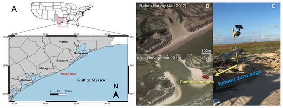
Figure 1.
(A) Study area. (B) Pre-Harvey satellite view of Cedar Lakes.We installed three solar-powered cameras (C,D) in Cedar Lakes, Texas, a site that experienced frequent wave runup flooding and was breached during Hurricane Harvey. The cameras were installed 2.5 m above the ground. The closest distance to the shoreline was approximately 30 m.
A single annotator labeled all images in the dataset to ensure consistency. The annotator labeled only the visible portions of each image and classified the regions into seven classes: water, sky, dry sand, wet sand, rough sand, objects (debris), and vegetation, each corresponding to different processes controlling beach recovery.
We distinguished different types of sand based on texture and moisture content. “Dry sand” refers to sand with a smooth texture and low moisture content (bright color), indicative of aeolian transport. In contrast, “wet sand” has a smooth texture but high moisture content (dark color), suggesting recent inundation. “Rough sand” exhibits a rough texture with intermediate moisture content or organic crust, potentially a sign of recent precipitation, and, like “wet sand,” cannot be transported via aeolian transport.
In our approach to distinguishing between these sand deposits, our first step was to separate the “rough” sand from the “wet” and “dry” sand, based primarily on its distinctive texture. Following this, we divided the “wet” and “dry” sands based on their color distinctions. With this two-step classification, we annotated a dataset that can facilitate accurate and detailed analysis of beach recovery processes using image segmentation techniques.
2.2. CNN Training, Predicting, and Testing
2.2.1. Patchwise Training of CNN
We chose the Deeplab v3+ architecture, which incorporates a Resnet-18 model pretrained on ImageNet, to form the backbone of our CNN analysis for semantic segmentation. Of the 156 high-quality images, we used 132 to train Resnet-18, following previous studies that indicated over 100 images sufficient for reliable semantic segmentation prediction via transfer learning [19].
To overcome GPU memory limitations, we cropped images into patches for CNN training. Cropping maintained spatial resolution, which is essential for investigating complex and often uncertain coastal regions.
We extracted non-overlapping local patches of from the original high-resolution () images, the greatest common divisor (GCD) of the input image’s width and height (see Figure 2). This patch size minimized zero padding from reshaping while preserving contextual information.
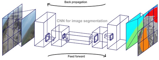
Figure 2.
An illustration of the patchwise training approach. High-resolution images (left) and their corresponding manual annotations (right) were divided into 12 patches for training. Only the verifiable regions (colored in the manual annotations) were labeled for CNN training, while ambiguous areas were excluded to prevent them from influencing the training process.
We divided our dataset of 132 images into 12 distinct patches per image, resulting in a total of 1584 patches for training. To augment the dataset, each patch was subjected to horizontal flipping with a 50% probability, random translations within a range of [−100, 100] pixels in the x and y directions, and random rotations within a [−20, 20] degree range.
During training, we utilized weighted cross-entropy loss in the classification layer to account for the imbalanced distribution of pixels across classes in the training set. We ensured that patches were randomly shuffled during each epoch, and we used a mini-batch size of eight. We employed Stochastic Gradient Descent (SGD) as the optimization method, with a momentum value of 0.9, an initial learning rate of 0.001, and a learning rate decay factor of 0.5 applied every five epochs for a total of 30 epochs.
We conducted CNN training using the Matlab Deep Learning library. We leveraged GPU parallel computing capabilities of both the RTX 2060 with Max-Q and the RTX 2080 Ti graphics cards. The training process took approximately two hours to complete.
2.2.2. Cut and Stitch Method for Prediction
After training the model, we adopted an enhanced cut and stitch method for the prediction to mitigate the translational variance. This method is designed to mitigate the effects of translational variance, which can affect the prediction of a pixel label depending on its relative position in an image. To address this, we discarded 160 pixels from the edge of each patch, except for those located at the perimeter of the original image. This strategy takes into account the recommendations found in a prior study, while also expanding the margin for error [20]. The increased margin is designed to better handle zero-padding during the feed-forward process, which can occur as the feature map size changes when information flows through the pooling layers. This approach is a modification of earlier recommendations, which suggested discarding only 20 to 40 pixels from the edge of each patch (Figure 3).
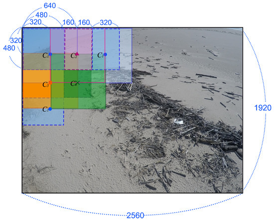
Figure 3.
An illustration of the cut and stitch method used for refining predictions. The method involves dividing the original image into 35 patches, which include 12 original patches (C1), 9 patches with an x-translation of 480 pixels (C2), 8 patches with a y-translation of 480 pixels (C3), and 6 patches with both x and y translations of 480 pixels (C4). These patches are then combined to create a single image segmentation prediction.
2.2.3. Model Testing with and without Ground Truth
We evaluate the model’s performance using two separate strategies: one with ground truth and the other without.
In order to assess the model’s predictive precision, we first matched its predictions with a variety of images from a test set. The set comprised 24 high-quality images, each meticulously hand-labeled to serve as ground truth. Precision and Intersection over Union (IoU) scores were then calculated to measure the congruity between the model’s predicted labels and the manual annotations in the test set.
On the other hand, we also assessed the model’s performance on general-quality images with lower quality (less verifiable) and luminance compared to the images it was trained on. The uncertain areas in theses general-quality images are larger, preventing the annotation of ground truth.
Given the lack of ground truth in this scenario, our testing predominantly rests on visual assessments of the model’s capability to discern changes in the image composition, which encompasses different regions such as wet sand, dry sand, and rough sand. Each of these regions signifies unique moisture levels and sand textures. These changes in areas within an image can serve as indicators of different beach processes, such as recent inundation, precipitation, or aeolian sand transport.
2.3. Estimation of Potential False Positive and Negative Error
This section outlines a method that estimates potential errors, such as false positives or negatives. We consider the difference between the highest and second-highest prediction probabilities for each pixel. These differences can highlight areas of uncertainty in the model’s predictions, where larger gaps typically signify a confident prediction, while smaller differences suggest a higher likelihood of class confusion. This analysis provides a measurable means to gauge potential errors.
We use matrix notation to streamline our calculations. We transform the two-dimensional pixel coordinate into a one-dimensional pixel coordinate d, with N representing the total number of pixels. For each pixel d, we define a binary matrix where when class k achieves the highest pixel score , and in all other cases. Similarly, we define another binary matrix where when class k has the second-highest pixel score , and in all other situations. We categorize the classes as follows: “Water” is , “Sky” is , “Dry sand” is , “Wet sand” is , “Rough sand” is , “Object” is , and “Vegetation” is .
Using this notation, we can calculate the area fraction for each class k in as follows:
We also estimate potential false positive/negative errors and the degree of uncertainty in predictions for each class. We focus on relevant classes (those likely to be confused) when measuring potential errors and exclude unrelated classes.
We focused on classes that share a domain of relevance (e.g., “Water” () and “Sky” () can be confused, while “Sky” () and “Vegetation” () are unlikely to be confused) when measuring the potential errors, excluding classes with no connection to one another.
We assumed that all adjacent classes could potentially exhibit some level of confusion. In order to represent the relevant pairs of classes, we employed a binary matrix , where both u and v are elements of class C. This is detailed in Equation (4).
Based on the symmetric matrix of relevant classes , we estimated the potential errors and the uncertainty of each class. We defined the potential false-negative error (upper bound) of an arbitrary class k using the Heaviside function ( for and otherwise) as follows:
Likewise, we defined the potential false positive error (lower bound) as:
where T was the total number of classes in C, which was 7 in this study. We established a uniform error threshold of for both Equations (5) and (6), irrespective of the number of relevant classes (i.e., the sum for each row in Equation (4)), in order to simplify calculations.
In other words, if an arbitrary pixel had the highest pixel probability of 0.6 for “Dry sand” () and the second highest pixel probability of 0.3 for “Rough sand” (), the pixel would be considered uncertain, as the difference between the two probabilities is less than 0.35 (). However, even if the difference between pixel probabilities for “Dry sand” () and “Water” () at another arbitrary pixel was less than 0.35, the pixel would not be deemed uncertain, since these two classes were determined to be less likely to be confused according to the binary matrix .
Finally, we define the uncertainty of a given class in each image as the average of the potential false negative and positive errors:
Our approach, which considers the second-highest pixel probability, could potentially be extended to the loss function during training, thereby enhancing the commonly used cross-entropy loss function. However, this concept lies beyond the current study’s scope and requires further exploration.
2.4. Blurry and Hazy Images Classification
In order to maintain the reliability of image segmentation results, it is critical to identify whether the image is blurry or hazy—a condition that often leads to misprediction (Figure A1)—prior to conducting the segmentation prediction.
In this section, we propose a method to classify these types of images. The method is based on the principle of measuring image sharpness, a key characteristic that directly impacts prediction accuracy.
There are various metrics for measuring image focus (sharpness), but selecting one that works accurately for all varying image conditions can be challenging [21]. Among many operators for defining blurriness, we choose the Laplacian-based operator, which is known to work well for most image conditions [22].
The Laplacian of an image, denoted by , is acquired by convolving the grayscale of the original image space, , with the discrete Laplacian filter F, as shown below:
The variance of this Laplacian yields the measure of image sharpness [23]:
In this research, we categorized images with a sharpness index exceeding 100 as being of normal clarity, whereas we classified those with a sharpness index below 100 as either blurry or hazy (Figure A2). To further distinguish between blurry and hazy images within a set of low-sharpness images, we developed a methodology that leverages the concept of image dehazing.
An image space can be decomposed into direct attenuation and the air-light [24]. The transmission and the scene radiance represent the amount of light reaching the camera and the original scene without scatter influence, respectively. The recovery of the original scene radiance can be achieved using the dark channel prior method, as follows:
where is a threshold value.
To evaluate the improvement in sharpness of the recovered scene radiance compared to the original image , we introduced the improvement ratio , defined as:
Our analysis revealed that the improvement ratio for hazy images was significantly larger than that for blurry images (Figure A1). Hence, by assessing the increase in the sharpness index after dehazing, we can determine whether an image is “blurry” and unsuitable for semantic prediction or “hazy” and appropriate for semantic segmentation.
2.5. Using Image Segmentation for Time Series Prediction
We delve into the application of image segmentation for time series prediction in this section, building upon the methods previously presented for measuring area fraction from image segmentation and estimating potential false negatives and positives.
Initially, we utilized these techniques to formulate a time series of the area fraction for each class, enabling us to track beach recovery post-storm. Our analysis spanned over a period of 220 days, from 16 November 2017 to 23 June 2018, during which images were captured at five-minute intervals. In an effort to maintain the accuracy of our semantic segmentation predictions, we omitted images captured during sunrise and sunset, times when the sun’s position alters rapidly. As such, our analysis relied on images taken between 7:00 AM and 6:00 PM each day.
We generated daily time series for each region and their potential error by averaging and for each image under “normal” and “hazy” conditions.
In line with our earlier discussions, we removed blurry images while retaining hazy images when measuring the time series. We defined a blurry image as any image that satisfied two conditions: (a) its sharpness index was less than 100 and (b) the sharpness index for its recovered (dehazed) image was less than 1000. Condition (b) was based on the assumption that, due to the large improvement factor for hazy images, all dehazed pictures, regardless of their original sharpness indices, would have a sharpness index of at least 1000 if the image was a hazy image.
3. Results and Discussion
3.1. Model Testing
3.1.1. Comparison with the Ground Truth
We applied our CNN model to predict different images in the test set to verify how our model performs for high-quality images. The predicted labels matched well with the hand annotation (Figure 4B,C), despite some noise near the interface of each class.

Figure 4.
(A) Beach image (B) beach image overlayed with the hand annotated ground truth (measured label) (C) beach image overlayed with the prediction from the model. The central part of (B) was left unlabeled, while every pixel was predicted in (C).
In general, the model accurately predicted the labeled regions, as reflected in Table 1. On the other hand, a closer look at the mean precision (95.1%) and the Intersection over Union (IoU) (86.7%) (also shown in Table 1) reveals that the rate of false-positive errors was more than double the rate of false negatives. These false positives could arise from predicting regions that were unlabeled or from making incorrect predictions.

Table 1.
Metrics for semantic segmentation performance.
We can also speculate that false-positive error was larger in classes with smaller areas, as the weighted Intersection of Union, which considered the number of pixels (size of each region), was greater than the mean Intersection of Union.
In addition to the general performance metrics, Table 2 presents the Precision and Intersection over Union (IoU) for each class. Notably, the “object” (IoU score: 74.8%) and “vegetation” (IoU score: 78.3%) classes exhibited lower prediction performance compared to other classes with IoU scores exceeding 90%. This was surprising, given that both classes had distinct shapes and boundaries that should have facilitated the CNN’s ability to differentiate the regions more effectively.

Table 2.
Precision and IOU for each classes.
A likely explanation for this lower prediction performance could be rooted in the inherent constraints of manual annotation. Marking objects and vegetation that exhibit diverse shapes proved to be substantially more laborious and difficult compared to the simpler task of labeling monotonous boundaries. Consequently, the actual objects and vegetation, along with the small areas surrounding them, were labeled as the “object” or “vegetation” classes for training and validation purposes. These inaccuracies, nonetheless, might have contributed to the lowering of Intersection over Union (IoU) scores for these respective classes.
Also, our analysis revealed that the primary source of false positives in the water region (IoU score: 79.0%) was associated with the incorrect prediction of high luminance areas as water labels, as depicted in Figure 5.

Figure 5.
(A) Beach image (B) Beach image overlayed with the hand annotated ground truth (measured label) (C) beach image overlayed with the prediction from the model. Due to the high luminance, the upper part of the region was left unlabeled in (B), where the model falsely identifies this as the water region.
To observe how classes were correctly classified, we compared the predicted and measured pixel counts for each class. The confusion matrix (Table 3) revealed that a small number of classes had contributed unequally to the false positives for specific classes.

Table 3.
Normalized confusion matrix. Classes in the column direction indicates predicted class and the row direction indicates measured class.
For example, the majority of predicted “water” pixels matched the measured water pixels (95.9% of measured water pixels), with the primary source of false positive errors for the “water” pixel being the misidentification of “wet sand” (2.1%) and “sky” areas (1.7%) as the “water” region. Confusion between “dry sand,” “rough sand,” “vegetation” (0.1%), and the “water” class was minimal.
Similarly, the model accurately classified the “dry sand” classes (94.6% of measured dry sand pixels), while most misclassifications for “dry sand” resulted from the confusion of “wet sand” and “objects” as “dry sand.”
Our observation of an uneven distribution of confusion among certain classes is consistent with our methodological assumptions. This evidence strongly supports our approach of concentrating on related classes when assessing potential errors.
3.1.2. Visual Comparison
We also put the model to test on images of more general quality, specifically those with less identifiable regions and low luminance levels, a departure from the type of images used during its training. This evaluation is crucial, as the majority of images captured by our camera system fall into this category.
Our CNN model demonstrated an effective capability to capture variations in different regions reflecting distinct beach processes, as shown in Figure 6.
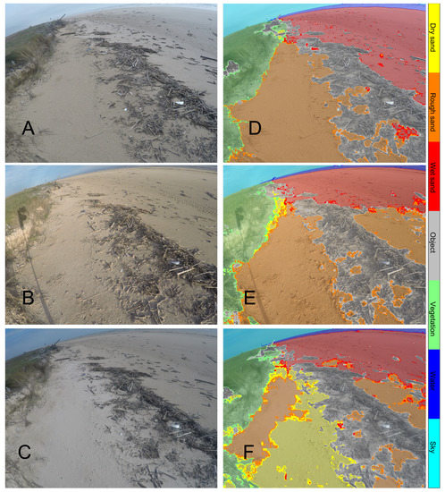
Figure 6.
(A) Beach image with a large wet sand area, (B) beach image with a large rough sand area, (C) beach image with dry sand overlaying the rough sand; (D–F) are the semantic segmentation predictions overlaid on the original images (A–C). Transparent labels indicate regions predicted with certainty (), while opaque labels represent the potential false-positive part () of the semantic segmentation.
Following inundation, the areas between debris and water were identified as wet sand, while the zones between vegetation and debris were classified as rough sand, which resulted from rainfall during the inundation (Figure 6D). As the wet sand dries, the rough sand expands and replaces the wet sand (Figure 6E). Subsequently, dry sand from the surrounding area overlays the rough sand, forming dry sand regions (Figure 6F).
Additionally, the potential false positives corresponded well with the “true” false positives of wet sand. This is clearly depicted in Figure 6F, where the false positive wet sand—marked by opaque red regions—is distributed throughout the center and along the edge of the dry sand area. On the other hand, there was a dense distribution of the potential false positive of the dry sand region (opaque yellow area) around the interface. This could be due to the less apparent and vague nature of dry sand compared to other sand regions, which leads to less accurate model predictions.
Furthermore, the model accurately predicted images taken from coastal cameras with different perspective, effectively tracking the progression of dry sand replacing the rough sand area (Figure 7). It excelled at capturing intricate details of objects and vegetation (Figure 7, E1 and E2), subtle variations in texture between rough and dry sand regions (Figure 7, E3), and the inherent uncertainty at their interface.
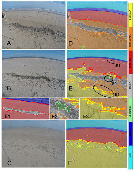
Figure 7.
(A) Beach image with a large rough sand area, (B) beach image where dry sand has replaced half of the rough sand, and (C) beach image where the dry sand has replaced all of the rough sand after aeolian transport; (D–F) are semantic segmentation predictions overlaid on the original images (A–C). Enlarged prediction results for the objects (E1), vegetation (E2), and the interface between the dry and rough sand regions (E3) demonstrate the accuracy of the model. Transparent labels indicate regions predicted with certainty (), while opaque labels represent the potential false-positive part () of the semantic segmentation.
Despite these strengths, the model faced difficulties in identifying the sand streamer—a narrow flow of saltating dry sand moving across the wet sand region (Figure 7C,F). These results indicate that the model is more responsive to texture variations—specifically between dry and rough sand (smooth–rough)—than to color disparities, such as those between dry and wet sand (bright–dark).
Interestingly, the model’s precision in distinguishing between objects (debris) and vegetation enabled us to discover that during the expansion of dry sand, most objects tend to become submerged, while vegetation shoots typically remain exposed (Figure 7E,F). This finding demonstrates the model’s utility in revealing subtle interactions between the physical environment and biological entities.
3.2. Estimation of Potential Errors for Different Image Conditions
In this section, we focus on the performance of our model under more challenging image conditions, and how these conditions might contribute to potential errors. Using our classification method, we analyzed a collection of images that were categorized as either normal (high or general quality), blurry, or hazy.
In order to avoid data overload, we made use of one image per hour for our study, even though the camera was initially capturing images every five minutes. From the twelve images available each hour, we selected one to apply our CNN model, enabling us to estimate two factors: the fraction of different areas in each image and the potential relative errors. Here, the potential relative error is defined as the ratio of the potential error to the corresponding area fraction.
We are focusing on the relative false positive error patterns, as the relative false negative error patterns are similar to the relative false positive error patterns. Including both would result in unnecessary redundancy within the graphical representations of our study. Given the similarity between these two error types, we can infer that the conclusions derived from analyzing one can be applied to the other.
Figure 8A illustrates the distribution of relative false positive errors in relation to the area fraction of dry sand in each image. Our observations reveal that for “normal” condition images, where the dry sand area fraction exceeds 20%, the relative false positive errors are primarily below 30%, with a few exceptions that deviate from this trend.
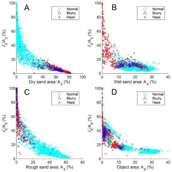
Figure 8.
The predicted area fraction and potential false positive () errors for distinct regions: (A) dry sand, (B) wet sand, (C) rough sand, and (D) object. Images are classified based on their sharpness index; those with an index greater than 100 are considered “normal.” Images with an index below 100 are further categorized as either “hazy” or “blurry,” depending on whether the dehazed (recovered) image has a sharpness index exceeding 1000.
This pattern of relative error for larger areas within “normal” condition images is also found in all other observed regions, such as wet sand, rough sand, and objects (Figure 8B–D). In instances where the wet sand area fraction is more than 10%, the relative false positive errors are predominantly below 20%. This pattern holds true for rough sand and objects area fractions larger than 20% and 10%, respectively. These observations suggest that the model reliably analyzes larger regions that are important for capturing beach processes, albeit with a handful of deviations from the overall trend.
On the other hand, “hazy” images usually displayed dry sand area fractions and relative potential errors that fell between those of ”blurry” and “normal” condition images, with dry sand area fractions around 60% and relative potential errors around 10%. The wet sand area fraction and potential error for “hazy” images had a wide range of values, ranging between 10% and 30% for area fraction and between 10% and 20% for relative potential error. Interestingly, these values were more similar to those of “normal” images than “blurry” ones. This discrepancy in wet area fraction values between “hazy” and “blurry” images aligns with the empirical finding that the model can more reliably predict hazy images than blurry ones. However, it was difficult to find any meaningful pattern for rough sand and objects.
In the case of “blurry” images, they typically showed a dry sand area fraction exceeding 60% with high certainty (relative potential error less than 10%), while the area fractions of wet and rough sand, as well as objects, were generally confined to less than 10%. This finding validates that, with a very low level of uncertainty, the model inaccurately identifies the blurry part of an image as dry sand, while failing to accurately capture the features of other regions.
The focus of this section has been to utilize the newly introduced potential false error metric to evaluate our model’s performance under various image conditions. However, this metric’s utility extends beyond this context, offering wider applications beyond beach imagery analysis. It may be particularly useful in quantifying uncertainty in ambiguous layers without clear boundaries, such as analyzing geological or glaciological mélanges, or defining chaotic structures within sedimentary basins. Thus, while our analysis has largely centered around beach imagery, the potential false error metric holds broader implications for other scientific domains.
3.3. Time Series of Beach Recovery
Finally, we examined the daily time series of area fractions for various regions throughout the span of the observation period. Although we did not factor in the potential errors for this analysis, detailed time series of potential errors can be found in the Appendix B (Figure A3).
A notable adjustment occurred on day 117 when the camera was replaced, resulting in a shift in the field of view from cross-offshore to cross-shore direction. This change led to a noticeable alteration of the time series (Figure 9), capturing more sky, water, and wet sand regions, while the previously dominant vegetation, objects, and rough sand regions became less prominent. Despite this change in perspective, evolving conditions of the beach remain the central focus of our study, as we explore the subsequent analysis.
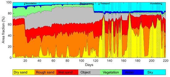
Figure 9.
Time series of daily average area fractions for different image classes. Blurry image days, characterized by a daily average sharpness index below 100 and a daily average sharpness index for dehazed images under 1000, are indicated by dotted lines.
During the coastal inundation on the 19th observation day, the object area fractions substantially increased from 5 percent to 20 percent, as large debris was transported to the back beach (Figure 10). This inundation event also triggered a transformation of the rough sand regions into wet sand, with the wet sand area approximately doubling after the flooding (Figure 9).
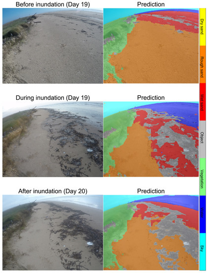
Figure 10.
The inundation at the day 19. Debris that later trapped the sand was brought to the beach surface during the inundation. Following a significant increase in wet sand during the flooding, the rain on day 20 transformed some of the wet sand into rough sand.
A notable feature in the time series shown in Figure 9 is the increasing trend in the dry sand area from day 120 up until day 214, when another coastal inundation event occurred. During this observation period, the dry sand area fraction fluctuates between zero and local maxima, with the peak value of each cycle gradually increasing from around 40 percent on day 125 to around 55 percent on day 205.
This increasing pattern of the dry sand area fraction between day 120 and 214 is different from the trend observed between day 1 and day 120 (Figure 9). In the earlier period, there were also small cyclic patterns for the dry sand area, indicating the occurrence of several aeolian transport events. However, the peak value of each cycle during day 1 to day 120 does not grow over time. This suggests that the beach state shifted from a non-recovering state, where aeolian transport temporarily increased the dry sand area without any long-lasting effects, to a recovering state, in which the dry sand area maxima of each cycle increased with every subsequent aeolian transport event.
Our analysis revealed that the transition from a non-recovering to a recovering state, ultimately leading to the vertical accretion of the beach, can be attributed to a massive aeolian transport event that took place on day 125 (middle and bottom Figure 11). This significant transport event not only caused an immediate increase in the dry sand area but also had lasting effects on the beach dynamics. The vertical accretion, which resulted from this massive transport event, altered the beach’s state in such a way that it became more conducive to accumulating dry sand over time.
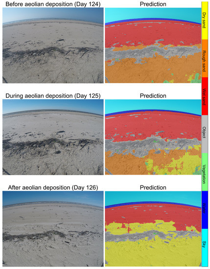
Figure 11.
The aeolian transport at day 124 to 126. Massive amounts of dry sand were moved from the berm to the beach on day 125, raising the beach elevation and changing the pattern of the dry sand area fraction after that.
As a result of this shift in the beach’s state, other coastal processes, such as the distribution of sediment and the growth of vegetation, were also influenced. The increase in dry sand area, combined with the gradual disappearance of objects and the expansion of vegetation, suggests a complex interplay between aeolian transport, sediment deposition, and ecological processes. As the beach continued to recover and grow vertically, these processes became more tightly interconnected, reinforcing the overall recovery process and further driving the observed changes in the beach’s state.
Evidence of this vertical growth can be seen in the combined area of dry, rough, and wet sand, which increased from 70 to 80 percent between day 120 and day 214, while the vegetation area grew from 0 to 5 percent. In contrast, the object area decreased from 15 to 0 percent. This indicates that the object area was replaced by sand and vegetation, as the sand buried the debris and vegetation continued to grow, further supporting the idea that the beach experienced vertical growth during this period (Figure 9).
4. Conclusions
In this study, we have employed a CNN technique for coastal monitoring using high-resolution complex imagery, with the goal of understanding beach recovery processes. The CNN model demonstrated an exceptional capability to detect indirect markers of coastal processes and beach recovery, such as water content and the texture of the sand, the presence and burial of debris, and the presence and quantity of vegetation that influence coastal dune formation. This was achieved through the adept interpretation and analysis of beach imagery, where the model was able to accurately differentiate these unique features, in spite of the complexity of the imagery, that spanned all possible weather and lighting conditions.
The proposed metrics used to quantify potential false positives and negatives allow a robust estimation of the uncertainty of the CNN model and thus evaluate its reliability in conditions where no ground truth is present. This method is general and can be easily extended to other cases. Additionally, we put forward a method to identify blurry beach images, which could potentially compromise the quality of the prediction, before proceeding with the image segmentation prediction.
After successful image segmentation and interpretation, the time series data revealed new insights into the beach recovery process. In particular, they highlighted the crucial role that rare aeolian transport events have on the beach recovery process, as they promote the initial vertical growth and set the conditions for further accretion and eventual recovery.
In summary, our study is the first to monitor beach recovery at a high temporal resolution using CNN techniques. Our proposed methods have broader applicability in coastal and ecological studies and can open the door to further enhanced environmental image-based monitoring techniques that deepen our understanding of complex ecosystems.
Author Contributions
Conceptualization, B.K. and O.D.V.; methodology, B.K.; software, B.K.; validation, B.K.; formal analysis, B.K. and O.D.V.; investigation, B.K.; resources, O.D.V.; data curation, B.K. and O.D.V.; writing—original draft preparation, B.K.; writing—review and editing, O.D.V.; visualization, B.K.; supervision, O.D.V.; project administration, O.D.V.; funding acquisition, O.D.V. All authors have read and agreed to the published version of the manuscript.
Funding
This research received no external funding.
Data Availability Statement
The data used in this study are available on request from the corresponding author.
Acknowledgments
This research was supported by the Texas A&M Engineering Experiment Station.
Conflicts of Interest
The authors declare no conflict of interest.
Appendix A. Image Segmentation for Blurry and Hazy Images
This appendix outlines an aspect of our CNN model that requires additional consideration, particularly when dealing with blurry images. The model has a tendency to misinterpret blurry areas in the image as dry sand or sky (Figure A1A,C), while it accurately processes the clear segments of the image (upper middle part in Figure A1A). Through empirical analysis, we discovered that these blurry images typically exhibit sharpness indices below 100 (Figure A2) for the image set we evaluated.
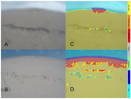
Figure A1.
(A) Blurry beach image, (B) beach image influenced by haze; (C,D) are semantic segmentation predictions overlaid on the original images (A,B). Semantic segmentation (C) misses most of the beach features, whereas (D) can predict most of the features, such as water, sky, objects, and vegetation. Both blurry (A) and hazy (B) images initially had low sharpness indices of 58.6 and 63.3; the hazy image demonstrated a significant improvement ratio of 20.86 post-dehazing, in contrast with the blurry image which only saw a marginal enhancement in its sharpness index ().
On the other hand, our observations revealed that images affected by haze often bear low sharpness indices, yet they are not necessarily blurry and remain amenable to analysis by the CNN model (Figure A1B,D). This difference in predictive quality implies that images with low sharpness indices can be classified into two categories: those that are “truly” blurry and hence difficult to interpret, and those that are still interpretable by the model (namely, “hazy” images).

Figure A2.
Comparison of images with different sharpness indices. Images with a sharpness index higher than 100 can be regarded as “normal” images (left column), while images with a sharpness index less than 100 are considered “blurry” images (right column).
Appendix B. Daily Average Time Series and the Potential Errors
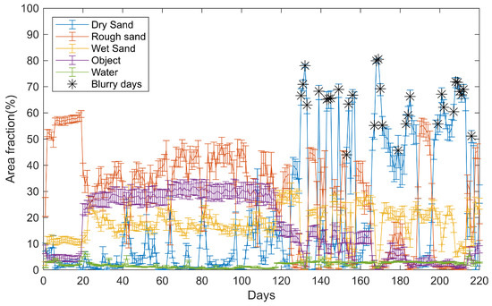
Figure A3.
Daily average time series for , with the corresponding potential false positive () and false negative () rates. Blurry image days are marked using asterisk.
References
- Morton, R.A.; Jeffrey, G.P.; James, C.G. Stages and Durations of Post-Storm Beach Recovery, Southeastern Texas Coast, U.S.A. J. Coast. Res. 1994, 10, 884–908. [Google Scholar]
- Coastal Engineering Research Center. Shore Protection Manual; Deptartment of the Army, Waterways Experiment Station, Corps of Engineers, Coastal Engineering Research Center: Vicksburg, MS, USA; Washington, DC, USA, 1984. [Google Scholar]
- Bascom, W.N. Characteristics of Natural Beaches. Coast. Eng. Proc. 1953, 1, 10. [Google Scholar] [CrossRef]
- Coco, G.; Senechal, N.; Rejas, A.; Bryan, K.R.; Capo, S.; Parisot, J.P.; Brown, J.A.; MacMahan, J.H.M. Beach response to a sequence of extreme storms. Geomorphology 2014, 204, 493–501. [Google Scholar] [CrossRef]
- Phillips, M.S.; Turner, I.L.; Cox, R.J.; Splinter, K.D.; Harley, M.D. Will the sand come back?: Observations and characteristics of beach recovery. In Proceedings of the Australasian Coasts & Ports Conference, Auckland, New Zealand, 15–18 September 2015; pp. 676–682. [Google Scholar]
- Masselink, G.; Austin, M.; Scott, T.; Poate, T.; Russell, P. Role of wave forcing, storms and NAO in outer bar dynamics on a high-energy, macro-tidal beach. Geomorphology 2014, 226, 76–93. [Google Scholar] [CrossRef]
- Senechal, N.; Coco, G.; Castelle, B.; Marieu, V. Storm impact on the seasonal shoreline dynamics of a meso- to macrotidal open sandy beach (Biscarrosse, France). Geomorphology 2015, 228, 448–461. [Google Scholar] [CrossRef]
- LeCun, Y.; Boser, B.; Denker, J.S.; Henderson, D.; Howard, R.E.; Hubbard, W.; Jackel, L.D. Backpropagation Applied to Handwritten Zip Code Recognition. Neural Comput. 1989, 1, 541–551. [Google Scholar] [CrossRef]
- Buscombe, D.; Carini, R.J. A Data-Driven Approach to Classifying Wave Breaking in Infrared Imagery. Remote. Sens. 2019, 11, 859. [Google Scholar] [CrossRef]
- Eadi Stringari, C.; Veras Guimarães, P.; Filipot, J.F.; Leckler, F.; Duarte, R. Deep neural networks for active wave breaking classification. Sci. Rep. 2021, 11, 3604. [Google Scholar] [CrossRef] [PubMed]
- Ellenson, A.N.; Simmons, J.A.; Wilson, G.W.; Hesser, T.J.; Splinter, K.D. Beach State Recognition Using Argus Imagery and Convolutional Neural Networks. Remote. Sens. 2020, 12, 3953. [Google Scholar] [CrossRef]
- Liu, B.; Yang, B.; Masoud-Ansari, S.; Wang, H.; Gahegan, M. Coastal Image Classification and Pattern Recognition: Tairua Beach, New Zealand. Sensors 2021, 21, 7352. [Google Scholar] [CrossRef] [PubMed]
- Long, J.; Shelhamer, E.; Darrell, T. Fully convolutional networks for semantic segmentation. In Proceedings of the 2015 IEEE Conference on Computer Vision and Pattern Recognition (CVPR), Boston, MA, USA, 7–12 June 2015; pp. 3431–3440. [Google Scholar] [CrossRef]
- Pashaei, M.; Starek, M.J. Fully Convolutional Neural Network for Land Cover Mapping In A Coastal Wetland with Hyperspatial UAS Imagery. In Proceedings of the IGARSS 2019—2019 IEEE International Geoscience and Remote Sensing Symposium, Yokohama, Japan, 28 July–2 August 2019; pp. 6106–6109. [Google Scholar] [CrossRef]
- Scarpetta, M.; Affuso, P.; De Virgilio, M.; Spadavecchia, M.; Andria, G.; Giaquinto, N. Monitoring of Seagrass Meadows Using Satellite Images and U-Net Convolutional Neural Network. In Proceedings of the 2022 IEEE International Instrumentation and Measurement Technology Conference (I2MTC), Ottawa, ON, Canada, 16–19 May 2022; pp. 1–6. [Google Scholar] [CrossRef]
- Seale, C.; Redfern, T.; Chatfield, P.; Luo, C.; Dempsey, K. Coastline detection in satellite imagery: A deep learning approach on new benchmark data. Remote. Sens. Environ. 2022, 278, 113044. [Google Scholar] [CrossRef]
- Goldstein, E.B.; Buscombe, D.; Lazarus, E.D.; Mohanty, S.D.; Rafique, S.N.; Anarde, K.A.; Ashton, A.D.; Beuzen, T.; Castagno, K.A.; Cohn, N.; et al. Labeling Poststorm Coastal Imagery for Machine Learning: Measurement of Interrater Agreement. Earth Space Sci. 2021, 8, e2021EA001896. [Google Scholar] [CrossRef]
- Buscombe, D.; Wernette, P.; Fitzpatrick, S.; Favela, J.; Goldstein, E.B.; Enwright, N.M. A 1.2 Billion Pixel Human-Labeled Dataset for Data-Driven Classification of Coastal Environments. Sci. Data 2023, 10, 46. [Google Scholar] [CrossRef] [PubMed]
- Kang, B.; Feagin, R.A.; Huff, T.; Duran Vinent, O. Stochastic properties of coastal flooding events—Part 1: CNN-based semantic segmentation for water detection. EGUsphere 2023, preprint. [Google Scholar] [CrossRef]
- Huang, B.; Reichman, D.; Collins, L.M.; Bradbury, K.; Malof, J.M. Tiling and Stitching Segmentation Output for Remote Sensing: Basic Challenges and Recommendations. arXiv 2019, arXiv:1805.12219. [Google Scholar]
- Pertuz, S.; Puig, D.; Garcia, M.A. Analysis of focus measure operators for shape-from-focus. Pattern Recognit. 2013, 46, 1415–1432. [Google Scholar] [CrossRef]
- Russell, M.J.; Douglas, T.S. Evaluation of autofocus algorithms for tuberculosis microscopy. In Proceedings of the 2007 29th Annual International Conference of the IEEE Engineering in Medicine and Biology Society, Lyon, France, 22–26 August 2007; pp. 3489–3492. [Google Scholar] [CrossRef]
- Pech-Pacheco, J.L.; Cristobal, G.; Chamorro-Martinez, J.; Fernandez-Valdivia, J. Diatom autofocusing in brightfield microscopy: A comparative study. In Proceedings of the 15th International Conference on Pattern Recognition. ICPR-2000, Barcelona, Spain, 3–7 September 2000; Volume 3, pp. 314–317. [Google Scholar] [CrossRef]
- Kaiming, H.; Jian, S.; Xiaoou, T. Single image haze removal using dark channel prior. In Proceedings of the 2009 IEEE Conference on Computer Vision and Pattern Recognition, Miami, FL, USA, 20–25 June 2009; pp. 1956–1963. [Google Scholar] [CrossRef]
Disclaimer/Publisher’s Note: The statements, opinions and data contained in all publications are solely those of the individual author(s) and contributor(s) and not of MDPI and/or the editor(s). MDPI and/or the editor(s) disclaim responsibility for any injury to people or property resulting from any ideas, methods, instructions or products referred to in the content. |
© 2023 by the authors. Licensee MDPI, Basel, Switzerland. This article is an open access article distributed under the terms and conditions of the Creative Commons Attribution (CC BY) license (https://creativecommons.org/licenses/by/4.0/).