Article

Vision-Aided Hyperspectral Full-Waveform LiDAR System to Improve Detection Efficiency

1
Changchun Institute of Optics, Fine Mechanics and Physics, Chinese Academy of Sciences, Changchun 130033, China
2
University of Chinese Academy of Sciences, Beijing 100049, China
3
Goertek Optical Technology Co., Ltd., Wei Fang 370700, China
*
Author to whom correspondence should be addressed.
Remote Sens. 2023, 15(13), 3448; https://doi.org/10.3390/rs15133448
Submission received: 25 April 2023 / Revised: 3 July 2023 / Accepted: 5 July 2023 / Published: 7 July 2023

Abstract

:
The hyperspectral full-waveform LiDAR (HSL) system based on the supercontinuum laser can obtain spatial and spectral information of the target synchronously and outperform traditional LiDAR or imaging spectrometers in target classification and other applications. However, low detection efficiency caused by the detection of useless background points (ULBG) hinders its practical applications, especially when the target is small compared with the large field of view (FOV) of the HSL system. A novel vision-aided hyperspectral full-waveform LiDAR system (V-HSL) was proposed to solve the problem and improve detection efficiency. First, we established the framework and developed preliminary algorithms for the V-HSL system. Next, we experimentally compared the performance of the V-HSL system with the HSL system. The results revealed that the proposed V-HSL system could reduce the detection of ULBG points and improve detection efficiency with enhanced detection performance. The V-HSL system is a promising development direction, and the study results will help researchers and engineers develop and optimize their design of the HSL system and ensure high detection efficiency of spatial and spectral information of the target.

1. Introduction

LiDAR (Light Detection and Ranging) and the imaging spectrometer are two different sensors. LiDAR acquires targets’ spatial point clouds and can work throughout the day without being influenced by weather and illumination conditions. Nowadays, LiDAR systems have been widely used in applications such as autonomous driving, topographic mapping, and reverse engineering [1,2]. The imaging spectrometer acquires high-resolution continuous spectral information and 2-dimensional spatial information of targets, and it has been widely used in object detection/classification [3], military reconnaissance [4], vegetation/agriculture analysis [5], and so on. They use different methods to detect targets, but have their own inherent shortcomings: LiDAR cannot acquire spectral information due to the monochromaticity of the laser source; the imaging spectrometer is a passive instrument and spectral detection may be affected by varying outdoor conditions, such as solar illumination, angle, shadow, and weather condition. In addition, the imaging spectrometer cannot acquire depth information, so spectra of different targets along the optical axis cannot be discriminated.
On the other hand, data from LiDAR and imaging spectrometer are complementary for target detection. Data registration and fusion [6,7] from them have been proven to perform better than separate sensors in target classification [8,9], mineral identification [10], and other applications. However, complex data registration caused by inconsistent spatial resolution and drawbacks of imaging spectrometers imposes constraints on their practical applications. To address these challenges, researchers proposed and developed multispectral LiDAR (MSL)/hyperspectral LiDAR (HSL) systems by replacing a monochromatic laser with a chromatic laser, which enables MSL/HSL systems to simultaneously acquire accurate spatial point clouds and spectra of targets within a single system. There are two methods to get a chromatic laser source for the MSL system. The 1064 nm laser emitted by Nd:YAG laser can be frequency-doubled to 532 nm or frequency-tripled to 355 nm. MSL systems employing this method have always been used in ocean research [11,12], atmospheric detection [13], and vegetation remote sensing [14]. However, laser wavelengths in these systems are typically not characteristic wavelengths for target detection, thus limiting their applicability. The other method is to combine light from different laser sources into one system [15,16]. In this approach, the detection wavelengths are carefully selected in advance based on specific requirements [17], ensuring that they are characteristic wavelengths for target detection. However, due to the large volume and complexity of the system, the number of detected wavelengths is often limited. Reported MSL systems have only a maximum of four channels [8,18] based on this method.
With the development of nonlinear optic technology [19], supercontinuum laser (SC-laser) can emit broadband laser pulse referred to as “white laser”. By replacing the monochromatic laser with a SC-laser, researchers from Finland [20] pioneered the development of the world’s first hyperspectral LiDAR (HSL) in 2010. Since then, scholars from Finland [21,22], China [23,24,25], and America [26] have developed various HSL prototypes for vegetation quantitatively sensing [27], mineral detection and classification [28], agricultural management [29], etc. The HSL systems, which have more detection channels or even continuous spectral curves [24] than the MSL systems, provide a wider range of applications and greater advantages.
Nonetheless, current HSL prototypes are faced with the problem of low detection efficiency, which restricts their practical applications and commercial viability. The term “detection efficiency” is defined as the ratio between the number of target points and that of total points. In scenarios where the target is relatively small compared with the large field of view (FOV) of the HSL system or situated at a considerable distance from the system, the point cloud becomes sparse, resulting in an insufficient number of target points for accurate three-dimensional reconstruction and spectral analysis. Therefore, there is a pressing need to enhance the detection efficiency. Additionally, when multiple targets are sparsely distributed throughout the entire FOV, detection of the most useless background (ULBG) points also results in the issue of low detection efficiency. It is worth noting that the HSL system typically features a single laser output due to the high cost and low spectral power density of the SC-laser. The generation of point clouds is achieved through raster scanning across the entire FOV. The frame per second (FPS) of the system depends on spatial resolution, scanning element speed, and time consumption for detecting a single footprint. Unlike conventional LiDAR systems, the HSL system necessitates more time to acquire hyperspectral full-waveform backscattered signals at a single footprint in order to derive both distance and spectra [30]. Spatial resolution directly influences the density of the point cloud. While a high spatial resolution is advantageous for accurate target detection, it also leads to the detection of a greater number of ULBG points, thereby reducing the overall detection efficiency. In addition, data post processing is essential but it is complicated to classify targets from ULBG points [31,32]. If the HSL system focuses on the detection of target points and reduces the detection of ULBG points, it is without a doubt that detection efficiency will be improved. However, studies on this method are not reported in the literature.
Vision-aided systems can guide detection and decrease ULBG points, thus improving the detection efficiency of LiDAR. Vision-aided systems have been applied in various domains such as automatic driving, unmanned aerial vehicles (UAVs), and robotics for localization, navigation, or tracking purposes [33,34,35]. The camera is used in these vision-aided systems to sense the environment due to its advantages of large FOV, low cost, high FPS, and rich information. Object detection algorithms (ODAs) [36] are often used to identify targets and determine their positions on the camera image. Currently, ODAs can be categorized into two types: traditional ODA based on feature descriptor and ODA based on deep learning (DL) techniques. Traditional ODAs, such as the HOG detector, are effective in extracting objects from images but are limited in terms of robustness, detection accuracy, and speed. Moreover, performance degradation may happen due to environmental factors such as occlusion and illumination. ODAs based on DL techniques originated in 2012 when Krizhevsky [37] proposed that convolution neural networks (CNN) could learn robust and high-level feature representations. Since then, numerous ODAs based on DL techniques have been proposed and demonstrated their capabilities in object detection, including RCNN, SPPNet, SSD, YOLO, and many other networks. Among them, the YOLO series algorithms proposed by Redmon [38] are one-stage detectors and excel in real-time high-precision detection applications. The YOLO series algorithms have been developed for higher recall, accuracy, and speed [39] and applied in the industry domain.
Extrinsic parameters calibration between the camera and LiDAR is crucial in guiding the detection of vision-aided systems. The extrinsic parameters represent rigid body transformation between two systems. Many calibration methods have been developed by researchers [40,41,42] to calibrate them and achieve accurate data registration. The checkboard is a commonly-used calibration target and can help easily determine the correspondences between LiDAR and the camera. Correspondences can be established through image and point cloud processing algorithms, enabling the extraction of important features such as normals, lines, or key points. Subsequently, the extrinsic parameters can be computed by the singular value decomposition method (SVD).
In this paper, a novel vision-aided hyperspectral full-waveform LiDAR (V-HSL) system is proposed to enhance the detection efficiency of the current HSL system by reducing the detection of ULBG points. The detection process of the V-HSL system relies on target detection in camera images. A novel V-HSL system and a four-step detection method that enables synchronous detection of spatial and spectral information with high efficiency are presented in Section 2. Comparative experiments and results are presented in Section 3. The discussion and conclusion are presented in Section 4 and Section 5, respectively.

2. Materials and Methods

2.1. System Configuration

The V-HSL system consists of two subsystems: a camera (Daheng MER-161-61U3MC with an 8–50 mm zoom lens) and a 6-channel HSL subsystem, as displayed in Figure 1a,b. Images captured by the camera are processed by a computer. The HSL subsystem acquired spatial and spectral information of the target synchronously under the guidance of the camera. The HSL subsystem comprises several components, including a supercontinuum laser source (SC-laser), filters, a beam sampler, an off-axis parabolic mirror (OAP), a two-dimensional rotation stage, a high-width amplified photodiode detector (APD), a high-speed oscilloscope, etc. The SC-laser (SuperK Compact, NKT) emits continuous broadband pulsed laser, and the spectral power density is displayed in Figure 1c. A fiber collimator (Thorlabs CFC-8-B) is employed to collimate the laser output and reduce the divergence angle to less than 5 mrad. A filter wheel with six channels serves as the spectroscopic element, allowing for the selection of the transmission wavelength. A small portion of transmitted light is reflected by a beam sampler and two plane mirrors (M1 and M2) and finally focused into the APD detector to trigger the acquisition of the oscilloscope and calibrate jitters of laser power. The remaining laser passes through the 3.2 mm hole in the OAP mirror and interacts with the target. The backscattered light is collected by the OAP and converged into the APD detector. The received laser is coaxial with the transmitted laser. Optical signals are converted into electrical signals by the detector, and the hyperspectral full-waveform voltage signals are digitized by the oscilloscope. The optical part of the HSL subsystem and the camera are mounted on the rotation stage to achieve 3-dimensional detection. A python program controls data acquisition, processing, and motion of the rotation stage. Parameter specifications of the V-HSL system are listed in Table 1. The spectral resolution of channel 1 is higher than that of other channels because the SC laser has a low power density in the channel.

2.2. Working Principle of the V-HSL System

2.2.1. Overview of the V-HSL System

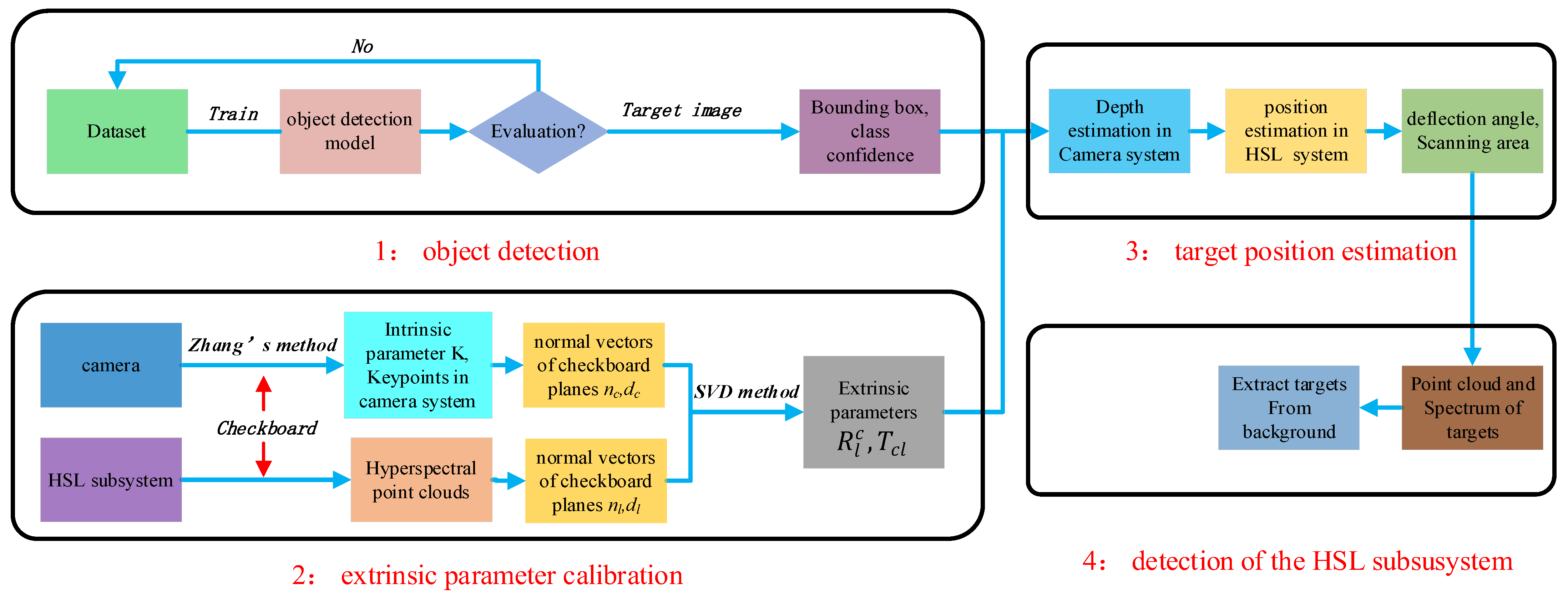
The novel V-HSL system proposed by us is an enhanced-version HSL system that has higher detection efficiency. To achieve this goal, we established the framework and developed preliminary algorithms in this section. Figure 2 illustrates the workflow of the proposed V-HSL system. Detection of the V-HSL system can be achieved by four steps: object detection, extrinsic parameters calibration, target position estimation, and detection of the HSL subsystem.
(1)
Object detection in camera images. Select and train an object detection model with a dataset that contains annotated targets. The well-trained model should predict the classes, positions, and confidences of targets in the camera plane with high accuracy and speed, which is a prerequisite for the detection of the HSL subsystem;
(2)
Extrinsic parameters calibration. Select a camera with a high resolution and proper focus, then calibrate its intrinsic parameter first. Fix the camera and HSL system on the same platform, then carry out extrinsic parameters calibration between the camera coordinate system and the HSL coordinate system;
(3)
Target position estimation in the HSL system. This step has two objectives: (1) rotate the outgoing beam to make it point to the center of the target; and (2) determine the minimum imaging range that contains the detected target. Target depth in the camera coordinate system will be estimated by the methods we proposed. Then, the target position in the HSL coordinate system will be derived and combined with the results of step 1 and step 2;
(4)
Detection of the HSL subsystem. The HSL subsystem will acquire point clouds and spectra of the target synchronously. Then, the target will be extracted from the background based on spectral differences.

2.2.2. Object Detection Based on YOLOv5 Model

In the V-HSL system, the YOLOv5 model proposed in 2020 [43] was selected to detect targets in the image plane. It has the advantages of high accuracy and speed. Furthermore, it is lightweight and can detect small objects effectively.
The structure of the YOLOv5 model is displayed in Figure 3 [44]. It consists of four modules: input, backbone, neck, and head. In the input module, data augmentation methods such as mosaic enhancement, HSV augmentation, image rotation, and CutMix can improve the detection performance of the model. In the backbone module, CSPdarknet53, which is composed of 23 (1 + 2 + 8 + 8 + 4) residual blocks, is utilized for feature extraction. Focus structure, Cross Stage Partial Network (CSPNet), spatial pyramid pooling (SPP), and deep residual network (ResNet) [45] are incorporated to optimize the network and improve detection performance. In the neck module, on the basis of the Feature Pyramid Network (FPN), the YOLOv5 model uses Path Aggregation Network (PANet) to transfer low-level features to higher-level features. The interference and prediction results, including location, confidence, and target class, are output in the head module. Three detection heads are employed to predict the targets with small, moderate, or large scales, respectively. Finally, non-maximum suppression method (NMS) will remove repeated detected targets and choose the optimal bounding box.
Overall accuracy (OA), precision, recall, m A P , and F-score are used to quantitatively evaluate the performance of object detection algorithms like YOLOv5. They can be calculated as Equations (1)–(5).
r e c a l l = T P T P + F N
p r e c i s i o n = T P T P + F P
O A = T P + T N T P + F P + T N + F N
F s c o r e = 2 × p r e c i s i o n × r e c a l l p r e c i s i o n + r e c a l l
m A P = 0 1 p r e c i s i o n d r e c a l l N
where T P ,   T N ,   F P ,   and   F N stand for true positive, true negative, false positive, and false negative, respectively. N is the number of categories in the dataset.
A large dataset for model training is necessary to obtain a well-trained model. Some open source datasets are available online. In this paper, we used the MSCOCO dataset to train the model [46] for the purpose of validating the performance of the V-HSL system. The MSCOCO dataset contains 80 categories, including car, boat, cat, dog, apple, orange, and other everyday objects. The well-trained YOLOv5 model, which achieved 56.8% m A P 50 on the MSCOCO dataset [47], can detect targets in 15 ms on the computer (Windows 11, Intel i5-10750H CPU, NVIDIA GeForce GTX 1650Ti, and PyTorch framework).

2.2.3. Extrinsic Parameters Calibration

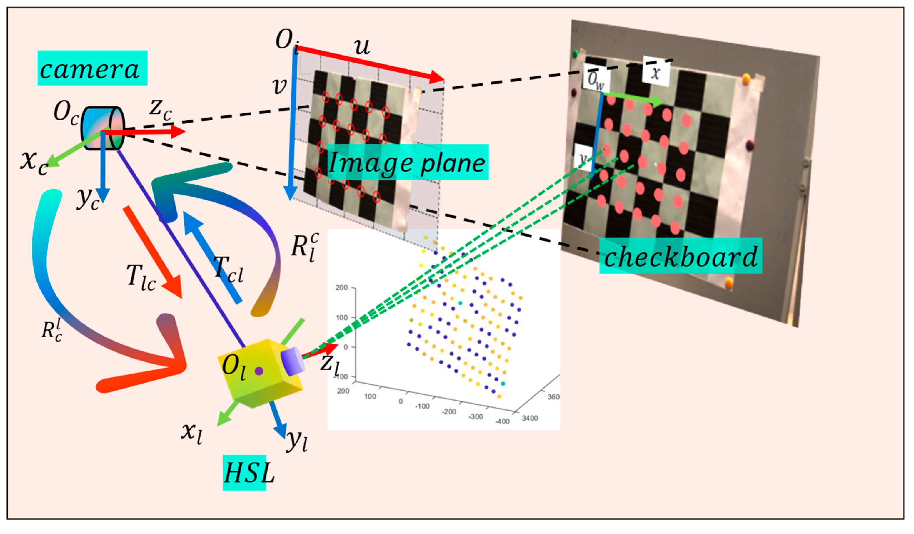
The extrinsic parameters, which consist of a rotation matrix and a translation vector, play a crucial role in data fusion and registration. Two Cartesian coordinate systems were established in the V-HSL system, as illustrated in Figure 4. In the camera system, the optical center was set as the origin and the optical axis as the z-axis. The x-axes and y-axes were aligned parallel to the direction of the imaging plane. The pinhole model was used to characterize the perspective projection of the camera because the distortion was minor. Similarly, the HSL coordinate system was established by setting the rotation axis of the 2-dimensional rotation stage at the initial position as x-axes and y-axes. The origin was the intersection of the rotation axis, and the z-axis could be determined by the right-hand principle. This part was to solve the rigid body transformation matrix R l c | T c l and [ R c l | T l c ] between the camera subsystem and the HSL subsystem.
To do this, the first step was to calibrate the intrinsic parameters of the camera, including the focus ( f x ,   f y ) and principal coordinate c x , c y . Intrinsic parameter K could be expressed as follows:
K = f x 0 c x 0 f y c y 0 0 1
According to the pinhole model [48], we had the following expression:
u , v , 1 = 1 z c t K R w c | T c w x w , y w ,   z w , 1
where X w x w , y w , z w denotes the coordinate value of the target in the world system. u , v represents the imaging point in the imaging plane. z c t refers to the target depth in the camera system. R w c 3 × 3 indicates the rotation matrix from the world coordinate system to the camera coordinate system, and T c w 3 × 1 is the coordinate value of the origin of the world system in the camera system.
We calibrated the intrinsic parameter K based on Zhang’s method [49] since it was simple, accurate, and of low cost. A checkboard plane was selected as the calibration target and key points could be detected by imaging process algorithms, specifically, the Harris Corner Detection algorithm. Then, the normal vector of the plane could be calculated. The calibration was executed with the MATLAB camera calibration application, which is based on Zhang’s method.
Then, we calibrated the extrinsic parameters using checkboards at different poses. The coordinate transformation from the HSL system to the camera system was expressed as Equation (8).
x c , y c , z c = R l c | T c l x l , y l , z l , 1
where X l x l , y l , z l and X c x c , y c ,   z c were matching points in the HSL system and camera system, respectively. Then, we established the correspondences of normal vectors in two coordinate systems. For the checkboard at a specific pose, coordinate values of key points p c i x c i , y c i , z c i in the camera system were derived. Meanwhile, the coordinate value of the laser footprint q l i x l i , y l i , z l i could be obtained directly in the HSL system. The normal vectors, denoted as n l i , d l i and n c i , d c i   , were determined by fitting the plane equation, as shown in Equation (9).
n c i p c i + d c i = 0 n l i p l i + d l i = 0
where i   denotes the i-th pose of the checkboard.
Therefore, we had the following equation:
R l c N l = N c
where N l and N c were 3 × n matrix representing normal vectors n l i ,   n c i of the checkboard plane at different poses in two coordinate systems, respectively.
Based on the correspondences of normal vectors, the extrinsic parameters could be calculated by the Singular Value Decomposition (SVD) method.
u , s , v t = s v d N l N c t R l c = v u t
Next, T c l could be calculated based on the distance relationship from the coordinate origin to the checkboard plane, as displayed in Equation (12).
n c T c l + d c = d l
T c l could be calculated as Equation (13):
T c l = n c t n c 1 n c t d l d c
The rotation matrix R c l   and translation vector T l c   from the camera system to the HSL system could be derived as Equation (14).
R c l = R l c t T l c = R c l T c l  

2.2.4. Target Position Estimation in the HSL System

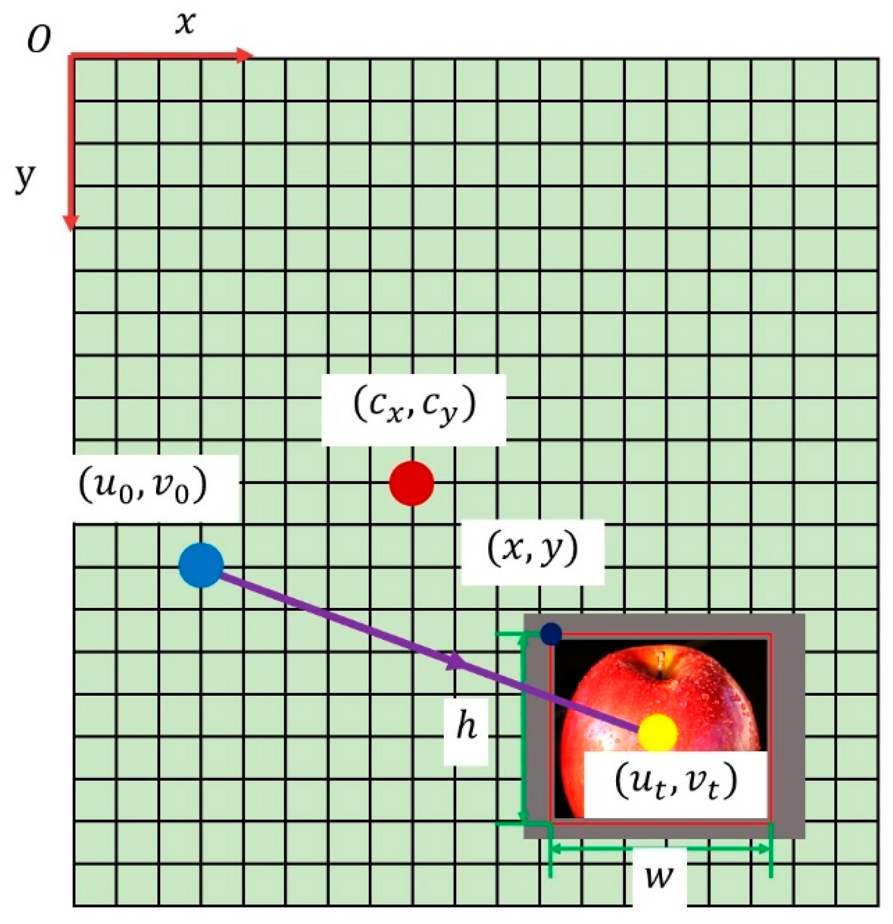
As shown in Figure 5, the location of the target in the imaging plane was predicted in Section 2.2.2. From Section 2.2.3 we can obtain extrinsic parameters between two subsystems. To guide the HSL subsystem to move from the initial footprint to the target position T l x l t , y l t , z l t , we have to estimate the target depth z c t in the camera system. Once z c t is known, the coordinate value of the target position can be calculated as Equation (15).
x l t , y l t , z l t = z c t R c l n e c + T l c
where n e c is the directional vector of the target in the camera coordinate system. n e c can be calculated as Equation (16).
n e c = u t c x , v t c y , f f
By rotating the rotation stage to a deflection angle ( θ x t ,   θ y t ), the direction of the outgoing laser will be aligned with the target centroid. The deflection angle ( θ x t ,   θ y t ) is calculated with Equation (17).
θ x t = atan x l t z l t θ y t = atan y l t z l t
However, the depth value z c t is unknown for the monocular camera, which leads to θ x   and   θ y   being unable to calculate. Here, we provide three methods to estimate z c t .
Method 1: Directed calculation.
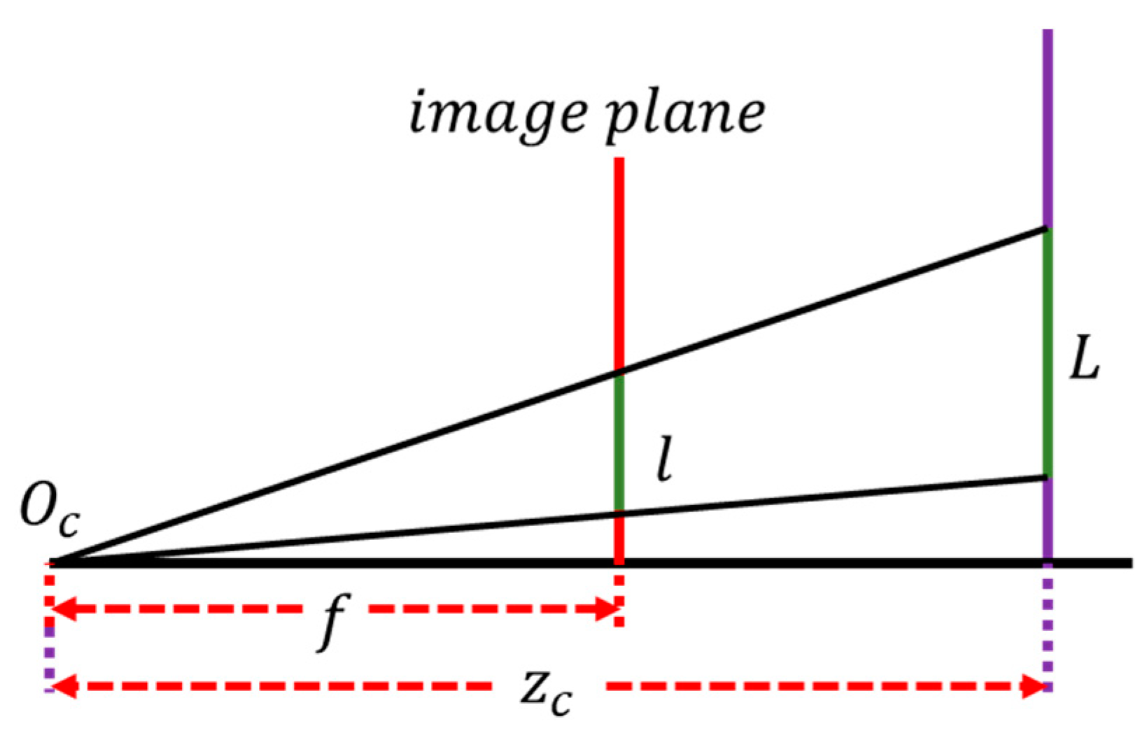
As show in Figure 6, if the real size of target L is known, we can get the corresponding image size l easily. According to triangle similarity, the target depth z c t can be calculated as f L l . f is the focal length of the camera.
Method 2: Stereo version.
In the proposed V-HSL system, since the camera moves with the rotation stage, one camera can realize the function of stereo vision by imaging in two positions: the original position P 1 0 ° , 0 ° and the other position P 2 θ 2 x , θ 2 y . The fundamental matrix can be estimated [50] with more than 7 corresponding points. The YOLOv5 model will detect target positions of imaging planes in both positions, which should obey the epipolar constraint and can be used to calculate the disparity. After that, z c t can be derived based on stereo version algorithms.
Currently, commercial stereo cameras make it easy for us to measure the target’s depth value directly. An example of such a camera is the Zed2i made by Stereolabs, which can detect targets at distances of up to 35 m at maximum with a depth accuracy of 7% at a distance of 30 m. It will meet application requirements in some scenarios.
Method 3: Depth estimation combined with the HSL system.
Since the HSL subsystem could obtain the 3D coordinate of the original laser footprint x l 0 , y l 0 , z l 0   before doing raster scanning, we proposed that the estimated value z c t could be approximately equal to the depth value z l 0 of the original footprint, as long as these constraints were satisfied:
(1)
Targets are close to the original footprint along the direction of the z-axis;
(2)
The angle between two optical axes of two subsystems is small.
For some applications such as ground targets detection for the airborne V-HSL system, these constraints can be met. Method 3 offers simplicity, as it allows for the direct acquisition of z c t without the need for complex calculations.
Once the depth value z c t is estimated, we can determine the position and range of the target in the HSL system by applying Equations (15) and (16), as displayed in the red bounding box in Figure 5. Meanwhile, deflection angles ( θ x t ,   θ y t ) can be calculated by Equation (17). The optical axis of the HSL subsystem is adjusted to align with the center of the target. Then, targets are detected directly by the HSL subsystem. Therefore, the acquisition of most ULBG points is avoided, resulting in higher detection efficiency. What is more, increasing the spatial resolution of the scanning area will acquire more detailed information about targets.
The aforementioned methods contain errors that will result in deviations from the exact target position in the HSL system. To ensure complete target detection, we have to expand the scanning area, as illustrated by the light gray area in Figure 5. The detect range should be set reasonably. We expanded the area by 30% on each side for the proposed V-HSL system. The larger the value is, the more information the proposed V-HSL system acquires, but the detection efficiency will become lower.

2.2.5. Detection of Spatial and Spectral Information Synchronously

The final goal of the V-HSL system is to detect point clouds and spectra of targets. We will show how the HSL subsystem works in this section.
The supercontinuum laser emits a narrow F W H M 1 ns broadband pulse laser in the HSL subsystem. The pulse interacts with the target and is then scattered to space. The receiving optical system collects the backscatter signals and directs them toward the APD detector. The APD detector converts the optical signal into the electrical signal, and the oscilloscope digitizes and records the full-waveform voltage signal at high speed. The wavelength-dependent backscattered intensity is expressed as Equation (18).
V r , λ = R λ P t , λ ρ λ D r 2 4 r 2 η s y s , λ η a t m , λ cos θ
where P t , λ , D r , ρ λ , η s y s , λ ,   η a t m , λ represent the transmitted intensity, the diameter of the receiving system, the reflectance of the target at the channel λ , the transmittance of the laser in the HSL system, and the atmosphere condition, respectively. θ is the incident angle of the laser, which is the angle between the laser’s incident direction and the normal direction of the target surface. R λ is the photoelectric response of the APD detector in the channel. To decrease noises and improve the signal-to-noise ratio (SNR), eight echoes of each channel in every laser footprint are acquired and averaged as the results. Furthermore, the influence of laser jitter can be eliminated by normalizing the backscattered intensity to the transmitted intensity P t , λ   .
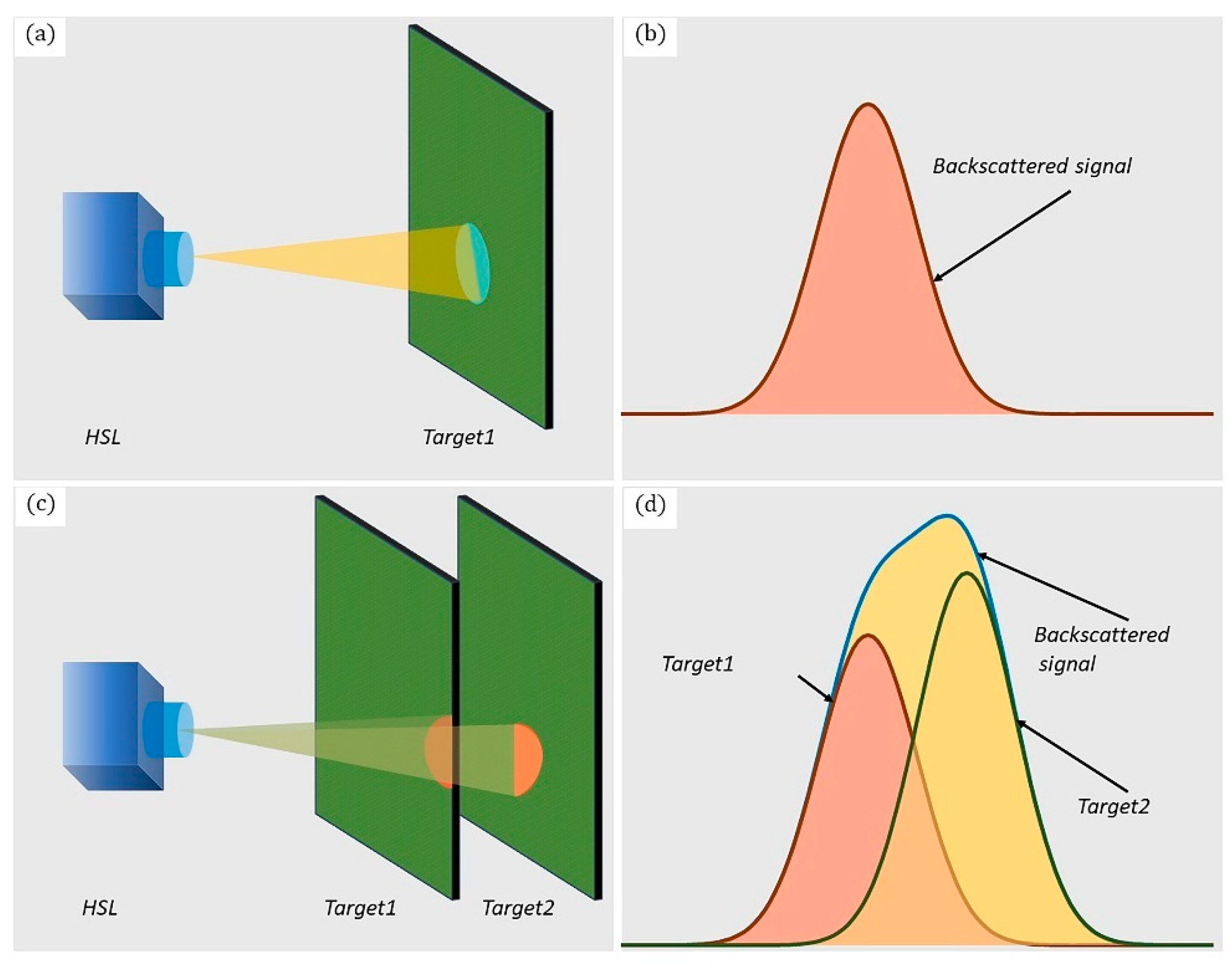
To derive spatial and spectral information, we extracted parameters by fitting the full-waveform backscatter signal with the Gaussian function, as described in Equation (19) and Figure 7a,b. In cases where multiple targets are present along the direction of laser transmission, the backscatter signal is the superposition of signals of sub-footprints from each object, which is named the “sub-footprint” effect. To extract the parameter of each target, we decomposed the superimposed waveform into separate signals, as displayed in Figure 7c,d and Equation (20). Waveform decomposition methods can be found in [51,52,53].
V r = V m , λ e 4 l n 2 t t m 2 F 2 + n o i s e
V r n = i = 1 n V r i
where V m , λ ,     t m ,   and   F represent the amplitude, position, and FWHM (full width at half maxima) of backscatter signal, respectively. V r i   and   V r n denote the waveforms of single and multiple echoes, respectively.
The distance r between the target and the HSL system was calculated by the time of flight (TOF) method. Together with the angles provided by the rotation stage, the 3D coordinates of laser footprints could be calculated and point clouds could be generated. The spectral reflectance was calculated by normalizing the echo power with that of the 99% standard diffuse whiteboard (SDWB) under identical measurement conditions, as shown in Equation (21). Echo energy was the integral of backscattered intensity to time and could be expressed as Equation (22).
ρ λ = E r , λ t E r , λ w
E r = t 0 t 1 V r , t d t V m FWHM
According to LiDAR equation Equation (13), the backscattered intensity of HSL is affected by the scatter characteristics of the target, measurement geometry, instrumental effects, and atmosphere effect [54]. Instrumental effects are considered constant when the system is fixed, and the atmosphere effect can be considered negligible during work. Therefore, the backscattered intensity is mainly influenced by measurement geometry involving distance and incident angle. In theory, the backscattered intensity is inversely proportional to the square of the distance. However, due to the influence of the near-distance effect [55], as the distance between targets and the system increases, the backscattered intensity will increase first, and then decrease, and, finally, follow the inverse square relationship when the distance exceeds a certain threshold. The incident angle also has a significant effect on backscattered intensity. Lambert’s cosine law is effective for diffused targets to calibrate incident effects, while natural targets typically do not follow it, because they exhibit not only diffuse effects but mirror effects. To eliminate the incident angle effect, the Lambert–Beckman model is employed to simulate the combination of the mirror and diffuse effects. Radiometric calibration [56] for distance and angle effect can eliminate their impact on spectral reflectance and considerably improve the accuracy and precision of results.
The rectangular shape of the image area includes both the identified target and adjacent ULBG points. Removing ULBG points to extract targets can be accomplished based on distance and spectral difference. Laser spectral ratios such as the normalized difference vegetation index (NDVI) have been used for object classification of multispectral/hyperspectral LiDAR point clouds [57,58,59]. An alternative method is to use Spectral Angle Mapping (SAM), which quantifies the spectral similarity between distinct spectral curves and is insensitive to spectral brightness resulting from variations in incident angle [32]. The spectral angle of two footprints X 1 x 1 , x 2 , x 3 , x 4 , x 5 , x 6 and Y 1 y 1 , y 2 , y 3 , y 4 , y 5 , y 6 is calculated as Equation (23).
θ = cos 1 i x i y i   i x i 2 1 2 i y i 2   1 2 , i = 1 6
where x i and y i are spectral reflectance of different channels. When the spectral angle θ is less than a threshold, two footprints are considered as belonging to the same object.

2.3. Performance Analysis and Evaluation

This paper introduces a novel approach aimed at enhancing the detection efficiency of the V-HSL system through the reduction of ULBG point detection. To quantitatively evaluate the detection efficiency of the V-HSL system, we proposed detection efficiency coefficient ε , which was calculated as Equation (24).
ε = N V t N V a N H t N H a = N V t N H a N V a N H t
with N V t and N V a the number of target footprints and total footprint for the V-HSL system, N H t and N H a the number of target footprints and total footprint for the HSL system. ϵ equals 1 for the HSL system because no ULBG points are removed. ϵ is larger than 1 for the V-HSL system, since N V t is greater than N H t and N V a is smaller than V H a . The larger the detection efficiency coefficient is, the better the detection performance of the V-HSL system.

3. Experiment

3.1. Materials

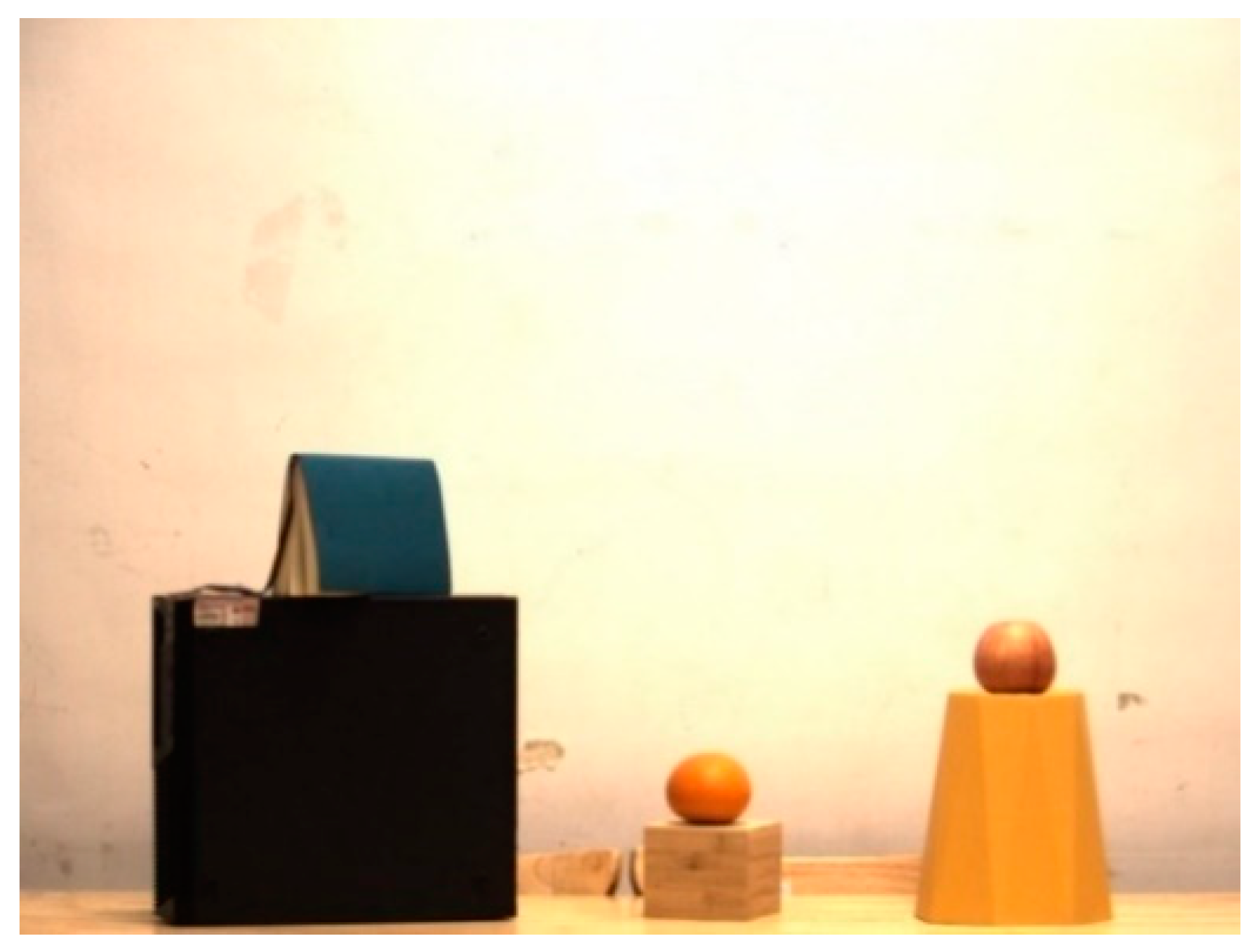
The experiments were carried out in the laboratory. Figure 8 provides a visual representation of the experimental setup, wherein 8 objects were positioned at an approximate distance of 5 m from the V-HSL system. These objects included a green notebook, a black metal box, an apple, an orange, a yellow plastic bin, a wooden box, a white wall, and a yellow wooden table. The apple and orange, which belonged to the subcategories of the MSCOCO dataset, were set as the detected targets for the experiment. The remaining objects served as the background in the experiment. Synchronous detection of spatial information and spectral information of the apple and the orange will be conducted by the HSL system and the V-HSL system, respectively. Then, we will compare the detection efficiency of these two systems.

3.2. Results

3.2.1. Detection of the HSL System

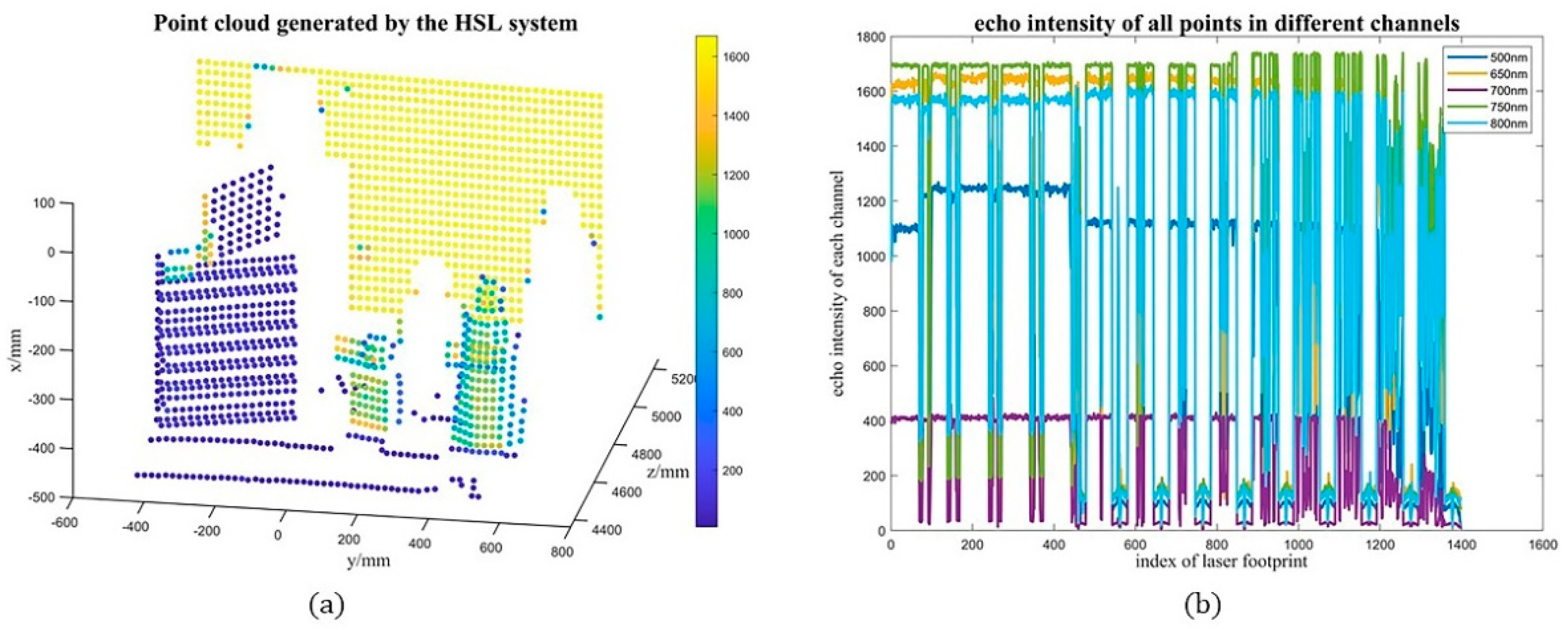
The HSL system is the HSL subsystem of the V-HSL system. The HSL system generated hyperspectral point clouds through raster scanning across the entire FOV. In this experiment, partial points that contained these objects (FOV: X: ±6°, Y: −6.75°~1.5°) were selected, as displayed in Figure 9a,b. The horizontal and vertical angle resolutions were 0.25° and 0.225°, respectively. The backscattered intensity of each footprint was obtained by processing hyperspectral full-waveform backscatter signals. Out of approximately 1400 detected points, only 30 points were identified as targets, with 15 points corresponding to the apple and 15 points to the orange. The results revealed the deficiency of low detection efficiency in the HSL system: ULBG points accounted for 98.93% of total points, and consumed a significant amount of time during acquisition and processing. In this case, the HSL system needs to decrease the spatial resolution to increase frame frequency, which will lead to less information and worse detection results for targets.

3.2.2. Detection of the V-HSL System

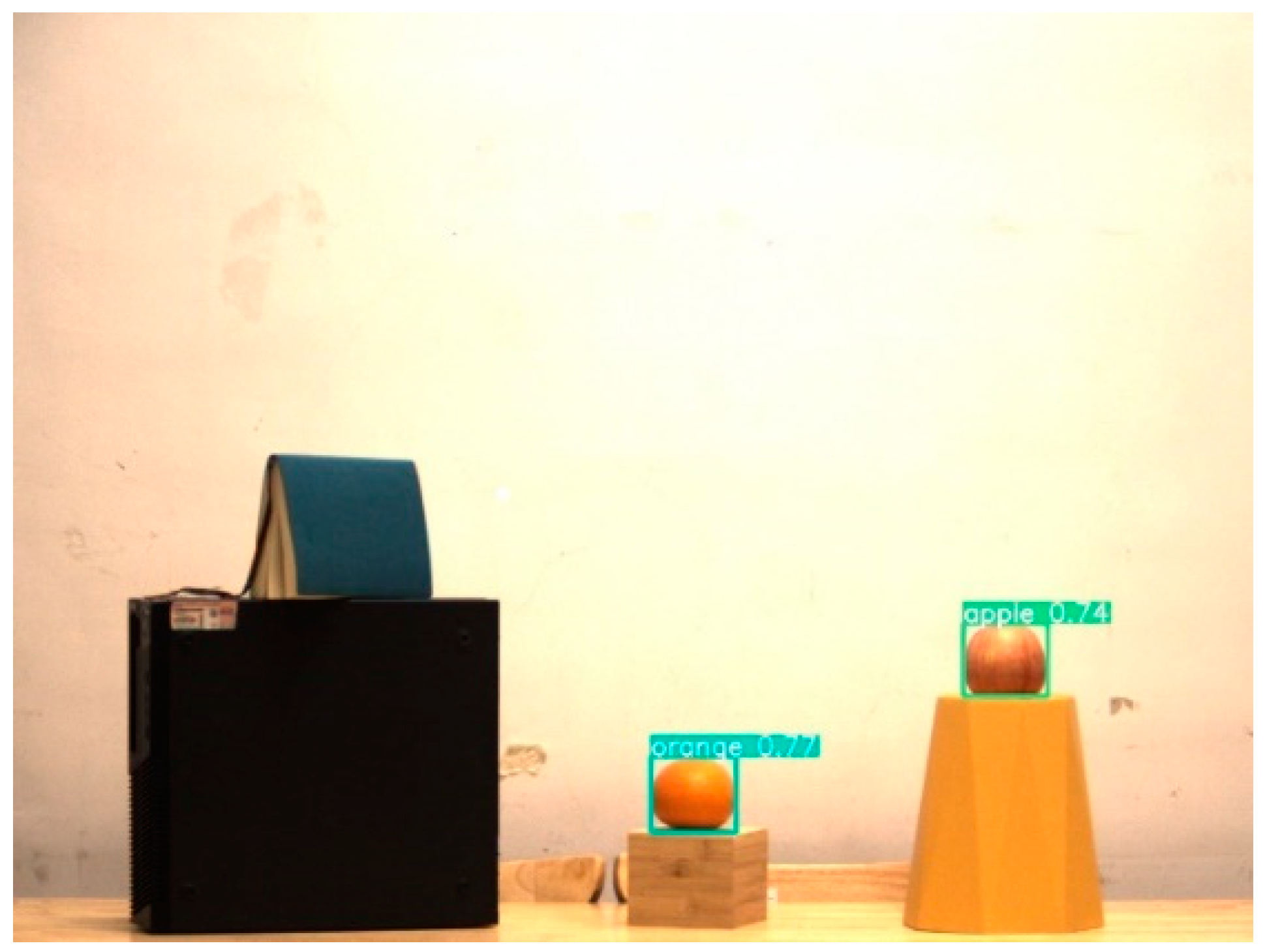
The position and range of the target were detected in the camera image. The well-trained YOLOv5 model detected the targets’ position x , y , range h , w , and categories in the image plane. Figure 10 visually presents the obtained results, demonstrating the correct detection of the apple and orange. The bounding box was the ideal detection area for the HSL subsystem. The starting point of the raster scan was the center of the bounding box x + w 2 ,   y + h 2 and the scanning area was a rectangular area determined by edge points x , y ; x + w , y ; x , y + h ; x + w , y + h .
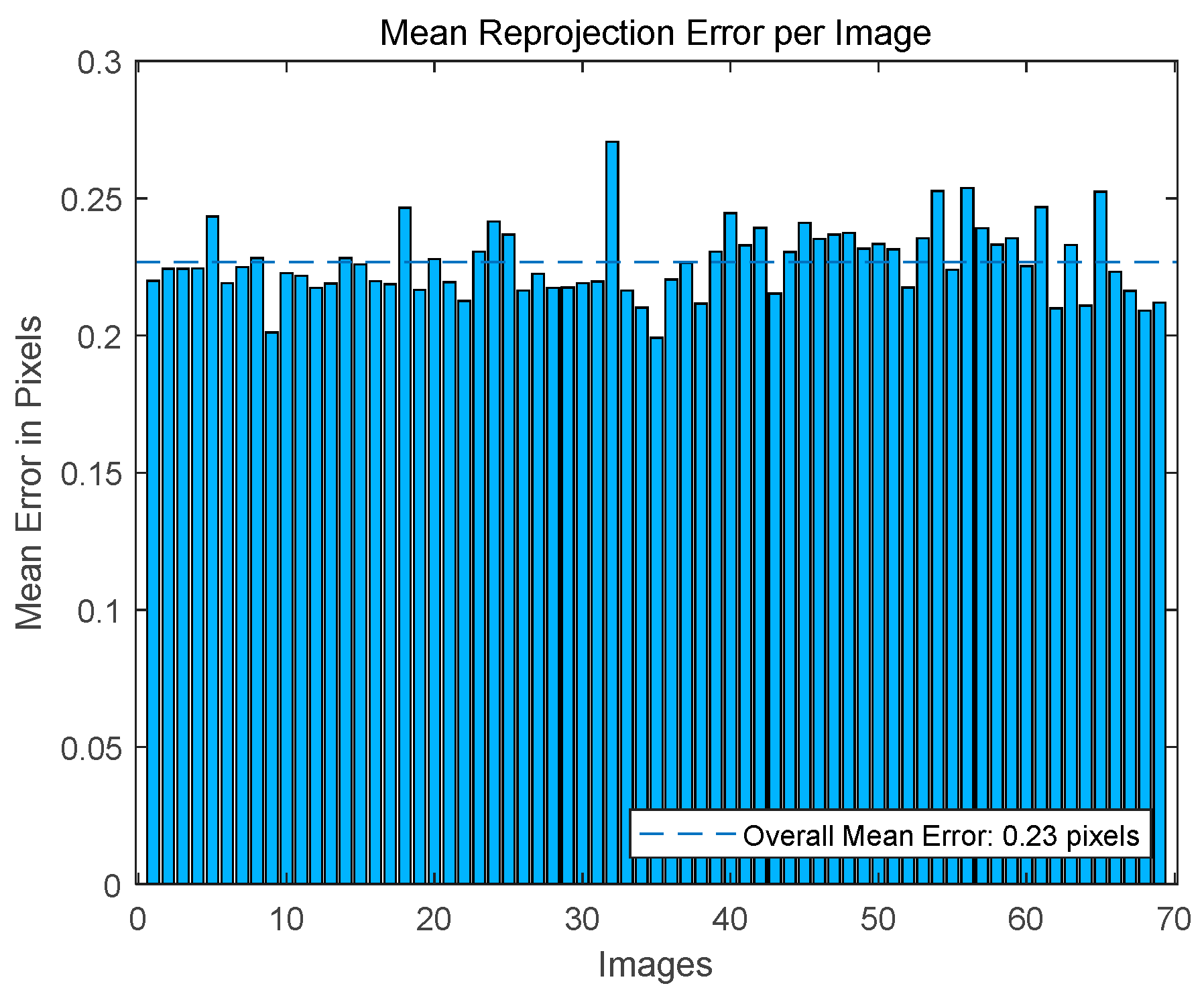
Intrinsic parameter calibration was performed by the MATLAB camera calibration application. The intrinsic parameter K was shown as follows and the reprojection error was displayed in Figure 11. The mean reprojection error was small; thus, the intrinsic parameter was well-calibrated.
K = 4939.02193589136 0 754.480785052691 0 4966.40991576761 587.900534020995 0 0 1
Extrinsic parameters were calibrated based on the correspondence of normal vectors of the checkboard at different poses. The calibration algorithm was illustrated in Section 2.2.3. The results, including R l c , T c l from the HSL system to the camera system and [ R c   ,   l T l c ] from the camera system to the HSL system, were presented as follows.
R l c , T c l = 0.999011595055844 0.00617225154970985 0.0440197257463624 115.996074475279 0.00526953419825832 0.999774039266112 0.0205937470814900 62.8053670933130 0.0441368888041658 0.0203414286698377 0.998818382553284 79.2180579153166 [ R c   ,   l T l c ] = 0.999011595055844 0.00526953419825832 0.0441368888041658 112.715939798007 0.00617225154970985 0.999774039266112 0.0203414286698377 60.4638101215847 0.0440197257463624 0.0205937470814900 0.998818382553284 85.5239657073251
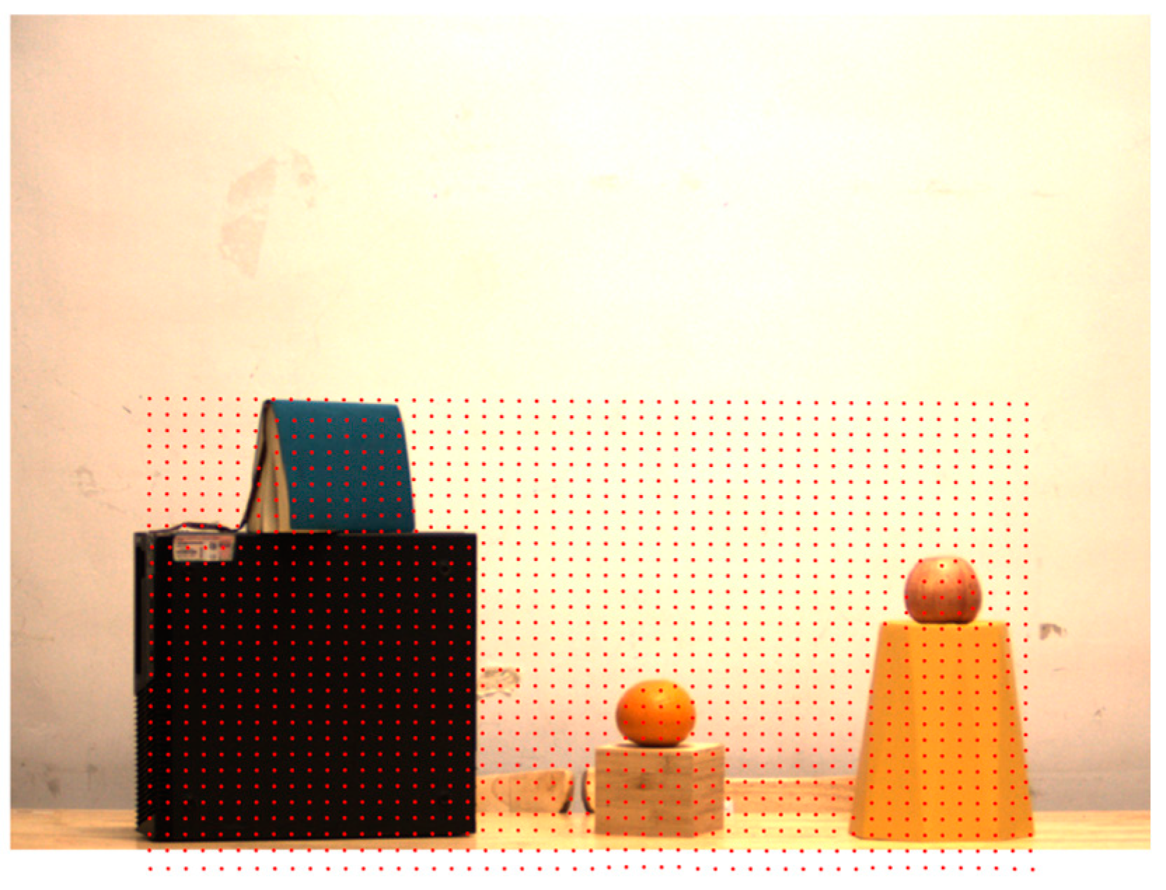
Considering that the ground-truth extrinsic parameters were unknown in advance, we reprojected the point cloud generated by the HSL onto the camera’s imaging plane to display the calibration results, as shown in Figure 12.
The angle between two optical axes of two coordinate systems was calculated, which was 2.7856 ° . The angle was small and the targets were close to the initial footprint, satisfying the constraints of Method 3. Therefore, we used Method 3 to estimate the depth values of two targets, and the corresponding results were displayed in Table 2.
The actual angle was provided by the point clouds of the HSL system. From the result, we found that the error was small, and we could guide the HSL subsystem to make the outgoing laser beam point to the center of the target, approximately. Similarly, we could determine the scanning area of the HSL subsystem.
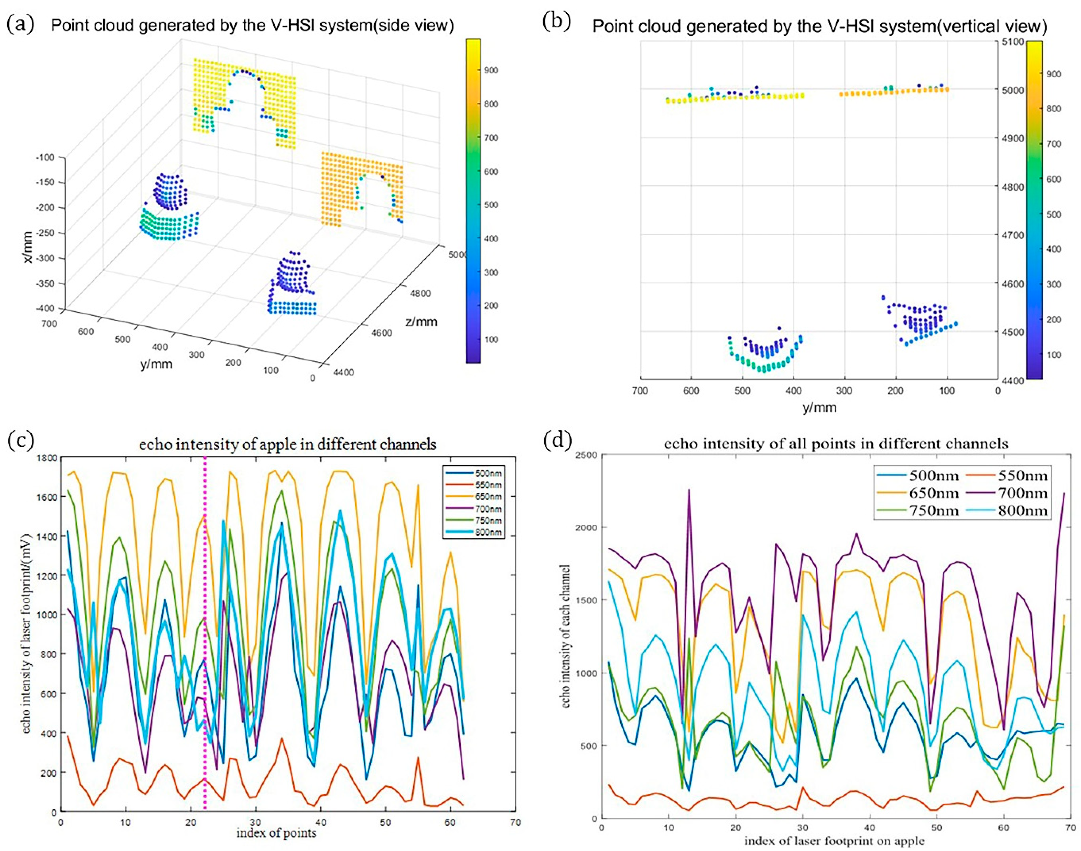
Finally, we increased spatial resolution and acquired point clouds and spectra of targets. We expanded the scanning area to ensure complete detection. Point clouds in 800 nm could be found in Figure 13a,b. A total of 500 points were obtained, with 130 points belonging to the orange (62) and the apple (68). Echo intensities at the edge of some objects (the white wall) were weaker than normal, which was the result of the “sub-footprint” effect. The backscattered intensity curves of the detected apple and orange were displayed in Figure 13c,d, respectively. They were plotted in the order of scanning. The variation of intensity was caused by the incident angle effect, which could be calibrated by radiometric calibration. The backscattered intensity curves of the background (wall, wooden box, and plastic bin) were not shown.
The echo intensity curves of the orange were displayed in Figure 14a, which could be transformed into spectra according to Equation (21). Similarly, spectral curves of the apple, the white wall, the wooden box, and the plastic bin could also be obtained. Spectral differences between different objects could be used to remove ULBG points and extract targets. Figure 14b presented a comparison of echo intensities of the orange and apple, revealing differences in some channels (700 nm, 750 nm, and 800 nm). To further illustrate the difference, 3D scatter plots were generated by plotting the intensity values of the two targets in three different channels. These scatter plots were depicted in Figure 14c,d, evidently demonstrating their differentiation.
The YOLOv5 model shows a time consumption of approximately 15 ms per image for object detection, which can be considered negligible. Meanwhile, the reduced number of ULBG points resulted in time savings during data acquisition and processing. For detection targets, because of a higher spatial resolution and a denser point cloud, the accuracy of the 3D reconstruction and spectral analysis became higher.

3.2.3. Evaluation of the V-HSL System

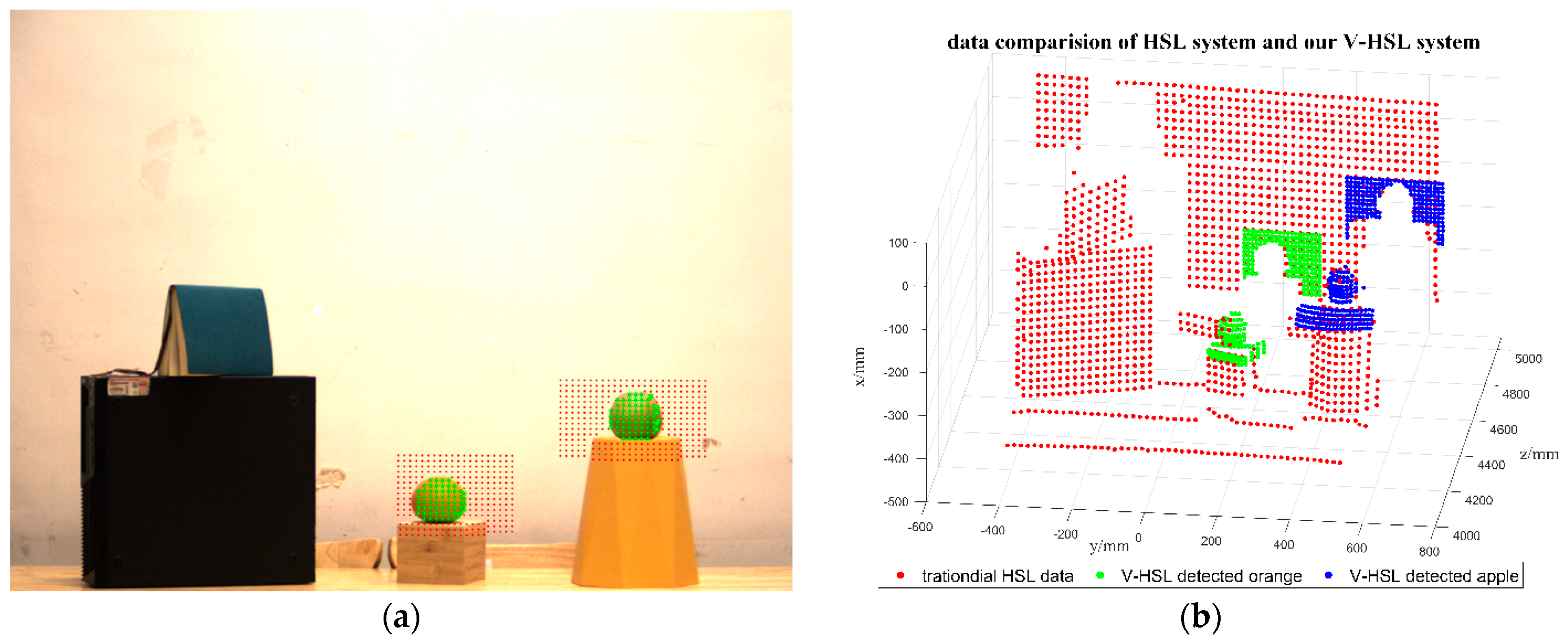
Based on the extrinsic parameter, we projected footprints of the V-HSL system in the camera image plane, as displayed in Figure 15a. Green and red points were laser footprints, of which green points were the detected target. It is evident that the V-HSL system successfully detects all targets, thereby maintaining the detection performance of the HSL system.
To compare the difference in detection performance between the HSL system and the V-HSL system directly, we plotted the point clouds acquired by two systems in the same coordinate system, as shown in Figure 15b. Red points represented laser footprints generated by the current HSL system, while green and blue points were point clouds for the orange and apple generated by the V-HSL system. From Figure 15b we could find that the V-HSL system acquired a denser point cloud of targets and fewer UBLG points compared with the HSL system, and thus had a better detection performance.
We evaluate the detection efficiency quantitatively based on the detection efficiency coefficient ε defined in Section 2.3. The result is presented in Table 3.
According to the result, total points decrease by 67% and the detection efficiency of the V-HSL system demonstrates a remarkable improvement by 13 fold.

4. Discussion

4.1. Comparison of the V-HSL System with Reported Works

We compared the performance of the proposed V-HSL system with three different sensors that have similar structures or methods, including the HSL system, the V-LiDAR system, and a single-pixel imaging LiDAR system. The relationship between the proposed V-HSL system, the HSL system, and the V-LiDAR system can be illustrated in Figure 16.

4.1.1. Comparison with the V-LiDAR System

The V-LiDAR system herein is the system that integrates a monochromatic LiDAR and a camera. Unlike the V-HSL system, two sensors (the LiDAR and the camera) in the V-LiDAR system are independent because both of them have high frame rates. By data registration based on extrinsic parameters, the V-LiDAR system is capable of obtaining more information on targets, including color, texture, and sparse point clouds, which are advantageous in comprehending the environment. Except for them, the V-HSL can acquire spectra of targets, with which users can discriminate different targets.
For some applications such as vision-aided landing of UAV systems, the V-LiDAR system utilized a straightforward approach to detect markers in the image plane since they are cooperative targets [34]. However, it raises high requirements for the real-time pose estimation of the system. The HSL system is unsuitable for such applications due to its low detection efficiency, but the V-HSL system holds promise for future applications, even for non-cooperative targets.

4.1.2. Comparison with the HSL System

The HSL system is a subsystem within the proposed V-HSL system. Compared with the HSL system that has images in the whole FOV, the V-HSL system has fewer ULBG points to acquire and process when detection targets are small and, thus, has a higher detection efficiency.
In addition, the complexity of data post processing differs between the two systems. All target and background points are classified as a whole for the HSL system, posing challenges for object segmentation and target classification [31,32,60]. However, the V-HSL system faces a comparatively easier task of target classification due to a smaller data volume and a reduced number of object categories. Separating targets from the surrounding ULBG points can be approached as a binary classification problem, even though the ULBG points may belong to different objects.
The V-HSL system is capable of acquiring a denser point cloud of targets, thereby conferring advantages in terms of three-dimensional reconstruction and spectral analysis of targets.

4.1.3. Comparison with the Single-Pixel Imaging LiDAR

The scanning single-pixel imaging LiDAR (SSPIL) [61] proposed by Jian shares the same idea with our work. The SSPIL system will perform a scanning search before starting imaging in order to save time consumption for imaging the background area, thus improving imaging efficiency. Experimental results show that the SSPIL system has the ability to perform long-distance imaging with high efficiency and resolution in sparse scenes. It is important to note, however, that the SSPIL system differs from the V-HSL system in terms of structures and working principles. The SSPIL system does not incorporate a camera, and the presence of targets is determined based on the backscattered intensity.

4.2. Outlook

In this paper, we proposed a 4-step method to realize the detection of the V-HSL system. However, the research for the V-HSL system is still in its initial phase and each step can be further improved to enhance performance and achieve higher detection efficiency.

4.2.1. Improvements in Object Detection Model

There are several aspects of this part that can be improved. Firstly, an illumination light source or an infrared camera is necessary to ensure object detection in low-light conditions. Secondly, the target size in the image plane is important for accurate detection. Careful selection of the camera, considering the application requirements, is necessary to strike a balance between focal length and target size. Thirdly, the YOLOv5 model can be further optimized or substituted with other models that have higher accuracy, recall, and speed. In cases where the trained model incorrectly detects or misses targets, collecting more trained data, applying state-of-the-art data augmentation techniques, and optimizing the network structure can improve the accuracy of the model. Fourthly, the V-HSL system can identify and classify targets based on their spectral characteristics. ULBG points that are detected as targets by mistake in the step can be removed, which means that the precision of the model in the V-HSL system can be allowed to be at a low level. Finally, careful consideration should be afforded to designing an appropriate scanning trajectory when multiple targets are detected.

4.2.2. Improvements in Extrinsic Parameter Calibration

In this paper, we calibrated extrinsic parameters by the SVD method based on the correspondence of the checkboard’s plane normal vector in two systems, which is a conventional and low-efficiency method. An alternative method for calibrating extrinsic parameters is direct linear transforms (DLT). If the camera remains stationary relative to the rotation stage, correspondence between laser footprints in the HSL system and the camera image plane can be established easily, because laser footprints are visible and their centroids can be easily identified. Solving the P n P problem can derive extrinsic parameters directly when there are more than three corresponding points. For the proposed V-HSL system, since the camera moves with the rotation stage, this method is not feasible.
The inclusion of backscattered intensity in addition to point clouds from the HSL subsystem offers the potential to simplify the process of extrinsic parameters calibration and improve calibration accuracy. It deserves in-depth study in the future.
In addition, the calibration accuracy is unknown in the proposed V-HSL system. Next step we will study how to evaluate it and enhance the calibration results.

4.2.3. Improvements in Target Position Estimation

Target position estimation is vital for the detection of the V-HSL system. Method 3 works well when the constraints are satisfied, but errors increase when targets are far from the initial position of the laser footprint. For a specific V-HSL system where Method 3 is applied, the working range should be determined in advance to ensure complete detection. It is convenient to use Method 1 to estimate depth value when the size of the target is known. In such cases, a synergistic combination of Method 1 and Method 3 may yield a better result. Method 2, despite its greater complexity, demonstrates a remarkable capability for accurately estimating depth values in the near distance. Additionally, commercial stereo cameras will simplify this method and facilitate the development of the V-HSL system. In the future, considering the accuracy and complexity, we will choose the best method among them for target depth estimation.

4.2.4. Improvements in Detection of HSL Subsystem

The V-HSL system was proposed to detect point clouds and spectra with high detection efficiency. To improve the accuracy of point clouds and spectra, data inversion algorithms for deriving echo energy and distance should be selected carefully. Methods used in the HSL system are applicable to the V-HSL system. Further, it is worth noting that backscattered intensities of laser footprints changed with the position, as the system did not calibrate the incident angle effect and distance effect. Therefore, radiometric calibration needs to be carried out to mitigate these effects and improve measurement accuracy. All of these methods can improve the detection performance of the V-HSL system.

5. Conclusions

To reduce the detection of ULBG points and improve the detection efficiency of the current HSL system, this study proposed a novel vision-aided hyperspectral full-waveform LiDAR (V-HSL) system first. The detection can be accomplished in four steps: (1) A well-trained objection detection model, YOLOv5, is employed to detect targets in the camera image. (2) Extrinsic parameters calibration between the camera system and the HSL system are performed. (3) The target position in the HSL system is estimated to determine the scanning area and starting point of the detected target. (4) Synchronous detection of spatial and spectral information of the target for the HSL subsystem.
The results of the comparative experiments demonstrate that the V-HSL system can largely reduce the acquisition and processing of ULBG points, and generate a denser point cloud of the target with more information, thus improving the detection efficiency of the HSL system. Compared with the current HSL system, the V-HSL system exhibits superior detection performance in scenarios where targets are either small or sparsely distributed. Further study on how to improve the accuracy of the object detection model, extrinsic parameters calibration, position estimation, and HSL system will be conducted in the future. It is anticipated that this work can help optimize the design of the current HSL system and develop a practical and commercial HSL instrument for synchronous detection of the target’s spatial and spectral information.

Author Contributions

Conceptualization, H.W., C.L. (Chao Lin) and Y.Z.; methodology, C.L. (Chao Lin), J.Z. and Y.Z.; software, H.W., J.Z. and Y.G.; validation, H.W., J.Z., Y.G. and S.W.; formal analysis, H.W., S.W. and W.S.; investigation, H.W., J.Z. and S.W.; resources, C.L. (Chengliang Li) and L.W.; data curation, L.W. and H.X.; writing—original draft, H.W.; writing—review and editing, H.W., C.L. (Chao Lin) and C.L. (Chengliang Li); visualization, H.W. and Y.G.; supervision, C.L. (Chao Lin), C.L. (Chengliang Li), J.Z., W.S. and Y.Z.; project administration, Y.Z.; funding acquisition, Y.Z. All authors have read and agreed to the published version of the manuscript.

Funding

This work was supported by the National Key Research and Development Program of China (No. 2021YFB3901000, 2021YFB3901004).

Data Availability Statement

Not applicable.

Conflicts of Interest

The authors declared that there are no conflict of interest.

References

  1. Royo, S.; Ballesta-Garcia, M. An Overview of Lidar Imaging Systems for Autonomous Vehicles. Appl. Sci. 2019, 9, 4093. [Google Scholar] [CrossRef] [Green Version]
  2. Li, Y.; Zhao, L.; Chen, Y.; Zhang, N.; Fan, H.; Zhang, Z. 3D LiDAR and multi-technology collaboration for preservation of built heritage in China: A review. Int. J. Appl. Earth Obs. Geoinf. 2023, 116, 103156. [Google Scholar] [CrossRef]
  3. Lv, W.; Wang, X. Overview of Hyperspectral Image Classification. J. Sens. 2020, 2020, 4817234. [Google Scholar] [CrossRef]
  4. Nardell, C.A.; Murchie, S.L.; Lucey, P.G.; Arvidson, R.E.; Bedini, P.; Yee, J.-H.; Garvin, J.B.; Beisser, K.; Bibring, J.-P.; Bishop, J.; et al. CRISM (Compact Reconnaissance Imaging Spectrometer for Mars) on MRO (Mars Reconnaissance Orbiter). In Proceedings of the Instruments, Science, and Methods for Geospace and Planetary Remote Sensing, Honolulu, HI, USA, 9–11 November 2004. [Google Scholar]
  5. Wang, C.; Liu, B.; Liu, L.; Zhu, Y.; Hou, J.; Liu, P.; Li, X. A review of deep learning used in the hyperspectral image analysis for agriculture. Artif. Intell. Rev. 2021, 54, 5205–5253. [Google Scholar] [CrossRef]
  6. Dalponte, M.; Bruzzone, L.; Gianelle, D. Fusion of Hyperspectral and LIDAR Remote Sensing Data for Classification of Complex Forest Areas. IEEE Trans. Geosci. Remote Sens. 2008, 46, 1416–1427. [Google Scholar] [CrossRef] [Green Version]
  7. Alonzo, M.; Bookhagen, B.; Roberts, D.A. Urban tree species mapping using hyperspectral and lidar data fusion. Remote Sens. Environ. 2014, 148, 70–83. [Google Scholar] [CrossRef]
  8. Gong, W.; Sun, J.; Shi, S.; Yang, J.; Du, L.; Zhu, B.; Song, S. Investigating the Potential of Using the Spatial and Spectral Information of Multispectral LiDAR for Object Classification. Sensors 2015, 15, 21989–22002. [Google Scholar] [CrossRef] [Green Version]
  9. Budylskii, S.S.D.; Tankoyeu, I.; Heremans, R. Fusion of lidar, hyperspectral and rgb datafor urban land use and land cover classification. In Proceedings of the IGARSS 2018, Valencia, Spain, 22–27 July 2018. [Google Scholar]
  10. Bauer, S.; Puente León, F. Spectral and geometric aspects of mineral identification by means of hyperspectral fluorescence imaging. tm-Tech. Mess. 2015, 82, 597–605. [Google Scholar] [CrossRef]
  11. Lu, X.; Hu, Y.; Trepte, C.; Zeng, S.; Churnside, J.H. Ocean subsurface studies with the CALIPSO spaceborne lidar. J. Geophys. Res. Ocean. 2014, 119, 4305–4317. [Google Scholar] [CrossRef]
  12. Zhou, Y.; Chen, Y.; Zhao, H.; Jamet, C.; Dionisi, D.; Chami, M.; Di Girolamo, P.; Churnside, J.H.; Malinka, A.; Zhao, H.; et al. Shipborne oceanic high-spectral-resolution lidar for accurate estimation of seawater depth-resolved optical properties. Light Sci. Appl. 2022, 11, 261. [Google Scholar] [CrossRef]
  13. Yu, S.; Liu, D.; Xu, J.; Wang, Z.; Wu, D.; Shan, Y.; Shao, J.; Mao, M.; Qian, L.; Wang, B.; et al. Optical properties and seasonal distribution of aerosol layers observed by lidar over Jinhua, southeast China. Atmos. Environ. 2021, 257, 118456. [Google Scholar] [CrossRef]
  14. Tan, S.; Narayanan, R.M. A Multiwavelength Airborne Polarimetric Lidar for Vegetation Remote Sensing: Instrumentation and Preliminary Test Results. IEEE Int. Geosci. Remote Sens. Symp. 2002, 5, 2675–2677. [Google Scholar] [CrossRef] [Green Version]
  15. Rall, J.A.R.; Knox, R.G. Spectral ratio biospheric lidar. In Proceedings of the Geoscience and Remote Sensing Symposium, Anchorage, AK, USA, 20–24 September 2004; Volume 1953, pp. 1951–1954. [Google Scholar]
  16. Gaulton, R.; Danson, F.M.; Ramirez, F.A.; Gunawan, O. The potential of dual-wavelength laser scanning for estimating vegetation moisture content. Remote Sens. Environ. 2013, 132, 32–39. [Google Scholar] [CrossRef]
  17. Sun, J.; Shi, S.; Yang, J.; Gong, W.; Qiu, F.; Wang, L.; Du, L.; Chen, B. Wavelength selection of the multispectral lidar system for estimating leaf chlorophyll and water contents through the PROSPECT model. Agric. For. Meteorol. 2019, 266–267, 43–52. [Google Scholar] [CrossRef]
  18. Wei, G.; Shalei, S.; Bo, Z.; Shuo, S.; Faquan, L.; Xuewu, C. Multi-wavelength canopy LiDAR for remote sensing of vegetation: Design and system performance. ISPRS J. Photogramm. Remote Sens. 2012, 69, 1–9. [Google Scholar] [CrossRef]
  19. Nantel, M.; Helmininack, G.A.; Gladysiewski, D.D.; Zhou, F.; Hershman, K.; Campbell, B.; Thomas, J. Supercontinuum generation in photonic crystal fibers for undergraduate laboratory. In Proceedings of the Tenth International Topical Meeting on Education and Training in Optics and Photonics, Ottawa, ON, Canada, 3–5 June 2007. [Google Scholar]
  20. Chen, Y.; Raikkonen, E.; Kaasalainen, S.; Suomalainen, J.; Hakala, T.; Hyyppa, J.; Chen, R. Two-channel hyperspectral LiDAR with a supercontinuum laser source. Sensors 2010, 10, 7057–7066. [Google Scholar] [CrossRef] [Green Version]
  21. Hakala, T.; Suomalainen, J.; Kaasalainen, S.; Chen, Y. Full waveform hyperspectral LiDAR for terrestrial laser scanning. Opt. Express 2012, 20, 7119–7127. [Google Scholar] [CrossRef]
  22. Kaasalainen, S.; Malkamaki, T. Potential of active multispectral lidar for detecting low reflectance targets. Opt. Express 2020, 28, 1408–1416. [Google Scholar] [CrossRef]
  23. Wang, Z.; Chen, Y. A Hyperspectral LiDAR with Eight Channels Covering from VIS to SWIR. In Proceedings of the IGARSS 2018—2018 IEEE International Geoscience and Remote Sensing, Valencia, Spain, 22–27 July 2018. [Google Scholar]
  24. Chen, Y.; Li, W.; Hyyppä, J.; Wang, N.; Jiang, C.; Meng, F.; Tang, L.; Puttonen, E.; Li, C. A 10-nm Spectral Resolution Hyperspectral LiDAR System Based on an Acousto-Optic Tunable Filter. Sensors 2019, 19, 1620. [Google Scholar] [CrossRef] [Green Version]
  25. Qian, L.; Wu, D.; Zhou, X.; Zhong, L.; Wei, W.; Wang, Y.; Shi, S.; Song, S.; Gong, W.; Liu, D. Optical system design for a hyperspectral imaging lidar using supercontinuum laser and its preliminary performance. Opt. Express 2021, 29, 17542–17553. [Google Scholar] [CrossRef]
  26. Powers, M.A.; Davis, C.C. Spectral LADAR: Active range-resolved threedimensional imaging spectroscopy. Appl. Opt. 2012, 51, 1468–1478. [Google Scholar] [CrossRef] [PubMed]
  27. Li, W.; Niu, Z.; Sun, G.; Gao, S.; Wu, M. Deriving backscatter reflective factors from 32-channel full-waveform LiDAR data for the estimation of leaf biochemical contents. Opt. Express 2016, 24, 4771–4785. [Google Scholar] [CrossRef] [PubMed]
  28. Chen, Y.; Jiang, C.; Hyyppa, J.; Qiu, S.; Wang, Z.; Tian, M.; Li, W.; Puttonen, E.; Zhou, H.; Feng, Z.; et al. Feasibility Study of Ore Classification Using Active Hyperspectral LiDAR. IEEE Geosci. Remote Sens. Lett. 2018, 15, 1785–1789. [Google Scholar] [CrossRef]
  29. Bi, K.; Gao, S.; Niu, Z.; Zhang, C.; Huang, N. Estimating leaf chlorophyll and nitrogen contents using active hyperspectral LiDAR and partial least square regression method. J. Appl. Remote Sens. 2019, 13, 034513. [Google Scholar] [CrossRef]
  30. Ilinca, J.; Kaasalainen, S.; Malkamaki, T.; Hakala, T. Improved waveform reconstruction and parameter accuracy retrieval for hyperspectral lidar data. Appl. Opt. 2019, 58, 9624–9633. [Google Scholar] [CrossRef]
  31. Chen, B.; Shi, S.; Gong, W.; Zhang, Q.; Yang, J.; Du, L.; Sun, J.; Zhang, Z.; Song, S. Multispectral LiDAR Point Cloud Classification: A Two-Step Approach. Remote Sens. 2017, 9, 373. [Google Scholar] [CrossRef] [Green Version]
  32. Chen, B.; Shi, S.; Sun, J.; Gong, W.; Yang, J.; Du, L.; Guo, K.; Wang, B.; Chen, B. Hyperspectral lidar point cloud segmentation based on geometric and spectral information. Opt. Express 2019, 27, 24043–24059. [Google Scholar] [CrossRef]
  33. Tang, Y.; Hu, Y.; Cui, J.; Liao, F.; Lao, M.; Lin, F.; Teo, R.S.H. Vision-Aided Multi-UAV Autonomous Flocking in GPS-Denied Environment. IEEE Trans. Ind. Electron. 2019, 66, 616–626. [Google Scholar] [CrossRef]
  34. Chen, X.; Phang, S.K.; Shan, M.; Chen, B.M. System Integration of a Vision-Guided UAV for Autonomous Landing on Moving Platform. In Proceedings of the 12th IEEE International Conference on Control & Automation, Kathmandu, Nepal, 1–3 June 2016. [Google Scholar]
  35. Chan, C.W.-H.; Leong, P.H.W.; So, H.K.-H. Vision Guided Crop Detection in Field Robots using FPGA-based Reconfigurable Computers. In Proceedings of the 2020 IEEE International Symposium on Circuits and Systems (ISCAS), Sevilla, Spain, 12–14 October 2020. [Google Scholar]
  36. Zou, Z.; Shi, Z.; Guo, Y.; Ye, J. Object Detection in 20 Years: A Survey. arXiv 2019. [Google Scholar] [CrossRef]
  37. Krizhevsky, A.; Sutskever, I.; Hinton, G.E. Imagenet classification with deep convolutional neural networks. Adv. Neural Inf. Process. Syst. 2012, 60, 84–90. [Google Scholar] [CrossRef] [Green Version]
  38. Redmon, J.; Divvala, S.; Girshick, R.; Farhadi, A. You Only Look Once: Unified, Real-Time Object Detection. In Proceedings of the 2016 IEEE Conference on Computer Vision and Pattern Recognition (CVPR), Las Vegas, NV, USA, 27–30 June 2016; pp. 779–788. [Google Scholar]
  39. Jiang, P.; Ergu, D. A Review of Yolo Algorithm Developments. In Proceedings of the The 8th International Conference on Information Technology and Quantitative Management, Cambridge, UK, 25–27 March 2022; pp. 1066–1073. [Google Scholar]
  40. Park, Y.; Yun, S.; Won, C.S.; Cho, K.; Um, K.; Sim, S. Calibration between color camera and 3D LIDAR instruments with a polygonal planar board. Sensors 2014, 14, 5333–5353. [Google Scholar] [CrossRef] [PubMed] [Green Version]
  41. Pusztai, Z.; Hajder, L. Accurate Calibration of LiDAR-Camera Systems using Ordinary Boxes. In Proceedings of the 2017 IEEE International Conference on Computer Vision Workshops (ICCVW), Venice, Italy, 22–29 October 2017. [Google Scholar]
  42. Geiger, A.; Moosmann, F.; Car, O.; Schuster, B. Automatic Camera and Range Sensor Calibration using a single Shot. In Proceedings of the 2012 IEEE International Conference on Robotics and Automation (ICRA), RiverCentre, Saint Paul, MN, USA, 14–18 May 2012. [Google Scholar]
  43. Jocher, G.; Stoken, A.; Borovec, J.; Chaurasia, A.; Xie, T.; Liu, C.; Abhiram, V.; Laughing, T. ultralytics/yolov5: v5. 0-YOLOv5-P6 1280 models, AWS, Supervise.ly and YouTube Integrations. Zenodo 2021, 10, 4679653. [Google Scholar]
  44. Jing, Y.; Ren, Y.; Liu, Y.; Wang, D.; Yu, L. Automatic Extraction of Damaged Houses by Earthquake Based on Improved YOLOv5: A Case Study in Yangbi. Remote Sens. 2022, 14, 382. [Google Scholar] [CrossRef]
  45. He, K.; Zhang, X.; Ren, S.; Sun, J. Deep Residual Learning for Image Recognition. arXiv 2015. [Google Scholar] [CrossRef]
  46. Lin, T.-Y.; Maire, M.; Belongie, S.; Girshick, L.B.R.; Hays, J.; Perona, P.; Ramanan, D.; Dollár, C.L.Z.P. Microsoft COCO: Common Objects in Context. arXiv 2014. [Google Scholar] [CrossRef]
  47. Ultralytics. YOLOv5. Available online: https://github.com/ultralytics/yolov5 (accessed on 24 July 2020).
  48. Lv, S.; Tang, D.; Zhang, X.; Yang, D.; Deng, W.; Kemao, Q. Fringe projection profilometry method with high efficiency, precision, and convenience: Theoretical analysis and development. Opt. Express 2022, 30, 33515–33537. [Google Scholar] [CrossRef]
  49. Zhang, Z. A Flexible New Technique for Camera Calibration. IEEE Trans. Pattern Anal. Mach. Intell. 2000, 22, 1330–1334. [Google Scholar] [CrossRef] [Green Version]
  50. Hartley, R.; Zisserman, A. Multiple View Geometry in Computer Vision, 2nd ed.; Cambridge University Press: Cambridge, UK, 2004. [Google Scholar]
  51. Wagner, W.; Ullrich, A.; Ducic, V.; Melzer, T.; Studnicka, N. Gaussian decomposition and calibration of a novel small-footprint full-waveform digitising airborne laser scanner. ISPRS J. Photogramm. Remote Sens. 2006, 60, 100–112. [Google Scholar] [CrossRef]
  52. Mountrakis, G. A linearly approximated iterative Gaussian decomposition method for aveform LiDAR processing. ISPRS J. Photogramm. Remote Sens. 2017, 129, 200–211. [Google Scholar] [CrossRef]
  53. Song, S.; Wang, B.; Gong, W.; Chen, Z.; Lin, X.; Sun, J.; Shi, S. A new waveform decomposition method for multispectral LiDAR. ISPRS J. Photogramm. Remote Sens. 2019, 149, 40–49. [Google Scholar] [CrossRef]
  54. Tian, W.; Tang, L.; Chen, Y.; Li, Z.; Zhu, J.; Jiang, C.; Hu, P.; He, W.; Wu, H.; Pan, M.; et al. Analysis and Radiometric Calibration for Backscatter Intensity of Hyperspectral LiDAR Caused by Incident Angle Effect. Sensors 2021, 21, 2960. [Google Scholar] [CrossRef] [PubMed]
  55. Wei, F.; Xianfeng, H.; Fan, Z.; Deren, L. Intensity Correction of Terrestrial Laser Scanning Data by Estimating Laser Transmission Function. IEEE Trans. Geosci. Remote Sens. 2015, 53, 942–951. [Google Scholar] [CrossRef]
  56. Qian, X.; Yang, J.; Shi, S.; Gong, W.; Du, L.; Chen, B.; Chen, B. Analyzing the effect of incident angle on echo intensity acquired by hyperspectral lidar based on the Lambert-Beckman model. Opt. Express 2021, 29, 11055–11069. [Google Scholar] [CrossRef] [PubMed]
  57. Suomalainen, J.; Hakala, T.; Kaartinen, H.; Räikkönen, E.; Kaasalainen, S. Demonstration of a virtual active hyperspectral LiDAR in automated point cloud classification. ISPRS J. Photogramm. Remote Sens. 2011, 66, 637–641. [Google Scholar] [CrossRef]
  58. Turner, M.D.; Kamerman, G.W.; Miller, C.I.; Thomas, J.J.; Kim, A.M.; Metcalf, J.P.; Olsen, R.C. Application of image classification techniques to multispectral lidar point cloud data. In Proceedings of the Laser Radar Technology and Applications XXI, Baltimore, MD, USA, 19–20 April 2016. [Google Scholar]
  59. Bi, K.; Xiao, S.; Gao, S.; Zhang, C.; Huang, N.; Niu, Z. Estimating Vertical Chlorophyll Concentrations in Maize in Different Health States Using Hyperspectral LiDAR. IEEE Trans. Geosci. Remote Sens. 2020, 58, 8125–8133. [Google Scholar] [CrossRef]
  60. Chen, B.; Shi, S.; Sun, J.; Chen, B.; Guo, K.; Du, L.; Yang, J.; Xu, Q.; Song, S.; Gong, W. Using HSI Color Space to Improve the Multispectral Lidar Classification Error Caused by Measurement Geometry. IEEE Trans. Geosci. Remote Sens. 2021, 59, 3567–3579. [Google Scholar] [CrossRef]
  61. Huang, J.; Li, Z.; Shi, D.; Chen, Y.; Yuan, K.; Hu, S.; Wang, Y. Scanning single-pixel imaging lidar. Opt. Express 2022, 30, 37484–37492. [Google Scholar] [CrossRef]
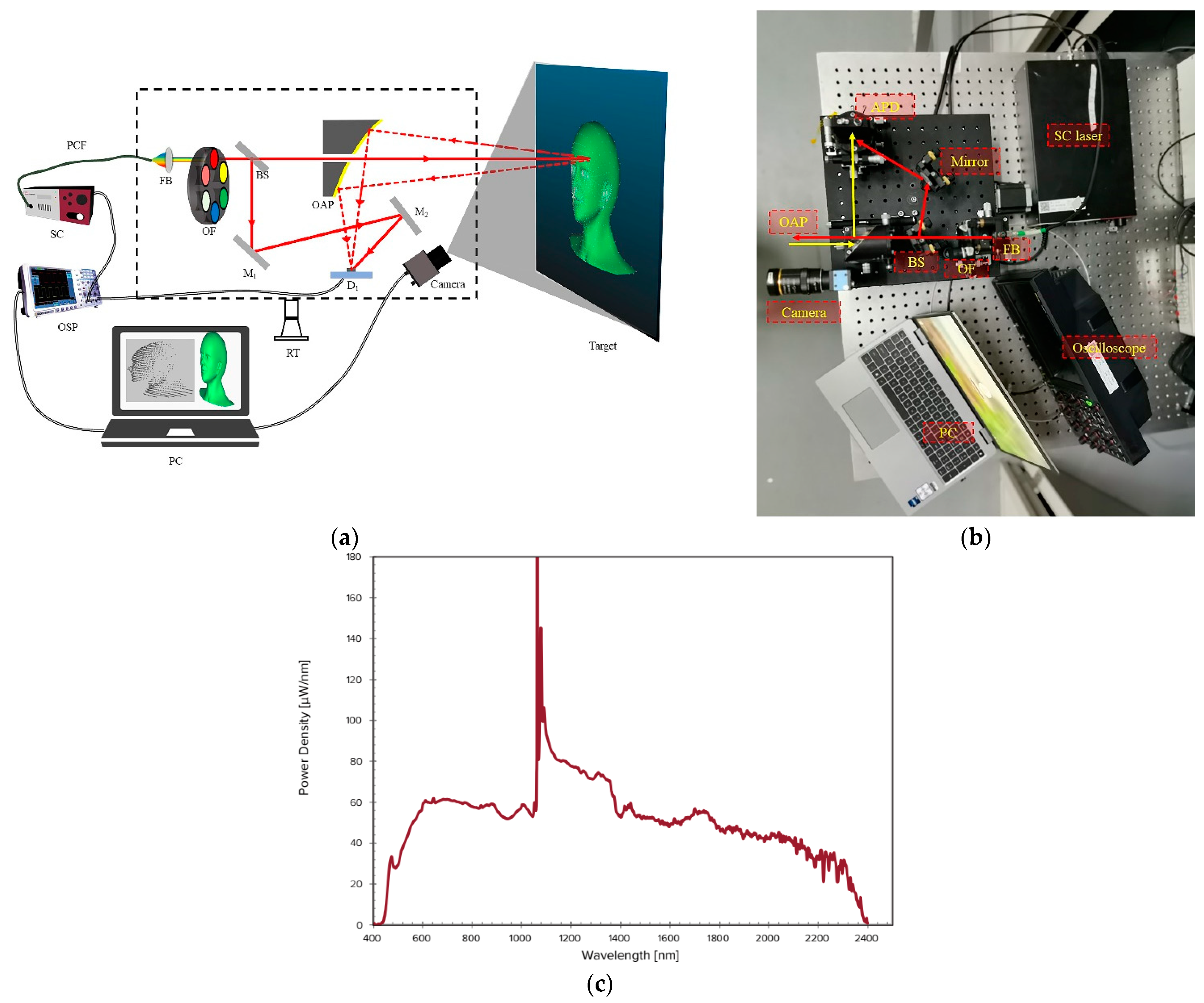
Figure 1. (a) Diagram of the V-HSL system. SC: supercontinuum laser; FB: achromatic fiber collimator; OF: optical filter; BS: beam sampler; M1/M2: fold mirror; OAP: off-axis parabolic mirror; D1: APD detector; OSP: oscilloscope; RT: rotation stage. (b) The V-HSL system, red line and yellow line are emitted and received lasers, respectively. (c) Spectral power density curve of supercontinuum laser (Superk-compact, NKT Photonics).
Remotesensing 15 03448 g001
Figure 2. Working flowchart of the proposed V-HSL system.
Remotesensing 15 03448 g002
Figure 3. Structure of YOLOv5 algorithm. BN: batch normalization. SPP: Spatial Pyramid Pooling.
Remotesensing 15 03448 g003
Figure 4. The coordinate systems of the HSL and camera subsystems.
Remotesensing 15 03448 g004
Figure 5. Diagram of vision-aided target detection. The apple is the detected target. c x , c y is the principal point of the camera. u 0 , v 0 is the image position of the original laser footprint. u t , v t is the position of the target. The purple line from u 0 , v 0 to u t , v t represents the motion direction of the outgoing beam from the original footprint to the target’s center.
Remotesensing 15 03448 g005
Figure 6. Depth estimation by method 1.
Remotesensing 15 03448 g006
Figure 7. (a,b) Laser irradiates on the surface of the target and the full-waveform backscatter signal fitted by the Gaussian function. (c) Laser irradiates on the edge of the target. (d) Signal acquired by the HSL system is the superimposition of the backscattered signal of different targets along the transmission direction.
Remotesensing 15 03448 g007
Figure 8. Image captured by the camera, including an apple, an orange, a plastic bin, a wooden box, a green notebook, and a black metal box, etc. Apple and orange were the targets, and the others were the background.
Remotesensing 15 03448 g008
Figure 9. (a) Point clouds acquired by HSL system in 650 nm channel. Color of points stands for the backscattered intensity, which could be used to calculate reflectance. (b) Backscattered intensity curves of laser footprints in different channels.
Remotesensing 15 03448 g009
Figure 10. Targets detected by YOLOv5 model.
Remotesensing 15 03448 g010
Figure 11. Mean reprojection error of camera intrinsic parameter calibration.
Remotesensing 15 03448 g011
Figure 12. Project LiDAR points on the imaging plane. Red points were projection points. Some points went beyond the image because the image area of the HSL subsystem was larger than that of the camera in the direction.
Remotesensing 15 03448 g012
Figure 13. (a) Point cloud of detected targets (the orange and apple) generated by the V-HSL system in the 800 nm channel. Color stands for raw backscattered intensities, which can be used to calculate reflectance. (b) Vertical view of (a). (c) Intensity curve of the apple arranged in the order of scanning. Magenta vertical dashed line represents results from one laser footprint. The variation in intensity is caused by the incident angle effect. (d) Intensity curve of the orange arranged in the order of scanning.
Remotesensing 15 03448 g013
Figure 14. (a) Comparison of spectra of the apple and orange in one laser footprint. (b) Backscattered intensity of the apple and orange in 3 different channels. (c) Intensity distribution diagram of the apple and orange in 3 channels (500 nm, 550 nm, 700 nm) to show their difference. (d) Intensity distribution diagram of the apple and orange in 3 channels (700 nm, 750 nm, 800 nm).
Remotesensing 15 03448 g014
Figure 15. (a) Reprojection of point clouds acquired by the V-HSL system on the image plane. Green points are projection points of targets, and we can observe the scanning area clearly from the picture. (b) Comparison of acquired data by the HSL system and the V-HSL system. Red points represent laser footprints generated by the HSL system, while green and blue points are point clouds of the orange and apple generated by the V-HSL system.
Remotesensing 15 03448 g015
Figure 16. Relationship between the current HSL system, the proposed V-HSL system, and the V-LiDAR system.
Remotesensing 15 03448 g016
Table 1. Parameter specifications of the vision-aided hyperspectral system.
ElementParameterValue
Filters in the
filter wheel
channelscentral wavelength/
spectral resolution
1500/30 nm
2550/10 nm
3650/10 nm
4700/10 nm
5750/10 nm
6800/10 nm
OAPmanufacturerThorlabs MPD269V-M03
diameter2 inch
back focus length6 inch
OscilloscopemanufacturerRIGOL MSO8204
bandwidth2 G
sample frequency10 G/s (max), 5 G/s(used)
APDspectral range400–1000 nm
diameter0.5 mm
bandwidth500 MHz
Rotation stageFOV±15 (vertical)
360 (horizontal)
CameramanufacturerDaheng MER-161-61U3MC
image size 1080 × 1440  
pixel size3.25 μ m
Table 2. Estimate value and error using Method 3.
OrangeApple
x y x y
Image position/pixel8169041186751
Estimate deflection angle/°2.9094.057.072.3257
Actual angle/°2.8753.93756.752.1375
Absolute error/°0.0340.11250.320.3944
Relative error/%1.182.864.748.8
Table 3. Comparison of detection efficiency between the HSL system and the V-HSL system.
Target PointTotal Points ε
HSL system3015001
V-HSL system13050013
Disclaimer/Publisher’s Note: The statements, opinions and data contained in all publications are solely those of the individual author(s) and contributor(s) and not of MDPI and/or the editor(s). MDPI and/or the editor(s) disclaim responsibility for any injury to people or property resulting from any ideas, methods, instructions or products referred to in the content.