Article

Distributed Coordination of Space–Ground Multiresources for Remote Sensing Missions

1
School of Information and Control Engineering, Xi’an University of Architecture and Technology, Xi’an 710055, China
2
School of Physics and Information Technology, Shaanxi Normal University, Xi’an 710119, China
3
School of Telecommunications Engineering, Xidian University, Xi’an 710071, China
*
Author to whom correspondence should be addressed.
Remote Sens. 2023, 15(13), 3362; https://doi.org/10.3390/rs15133362
Submission received: 6 May 2023 / Revised: 18 June 2023 / Accepted: 20 June 2023 / Published: 30 June 2023

Abstract

:
As data relay satellites (DRSs) play an increasingly important supporting role in remote sensing missions, efficient coordination across space–ground multiresources becomes a significant problem. Owing to the implementation problem of the centralized coordinate methods, this paper studies a distributed coordinate resource scheduling method which is realizable in the current space network structure. To be specific, we first formulate the multiple resource coordination problem into an MILP problem based on a modified time-expanded graph. Then, the problem is transferred and decomposed into subproblems for remote sensing satellite (RSS) systems and DRS systems to solve distributedly. Afterwards, we propose a distributed iterative scheme for the RSS systems and DRS systems based on alternating direction method of multipliers (ADMM), in which only the schedule information of the inter-satellite links are required to exchange between RSS systems and DRS systems. Simulation results are provided to validate the effectiveness of our distributed coordinated resource scheduling algorithm.

1. Introduction

Benefiting from the inherent wide coverage and potential overflight capability, remote sensing satellites (RSSs) are widely employed to observe specific targets for diverse missions, e.g., mapping, environmental monitoring, disaster surveillance, and national defense [1,2]. With the rapid growth of the information acquiring capability of the sensors on RSSs, how to download the huge amount of onboard data to the ground in time has become a great challenge for remote sensing missions. The length of time windows between RSSs and ground stations are usually very short (i.e., 5 min–10 min). To tackle this problem, data relay satellites (DRSs) have been deployed in geosynchronous Earth orbit to provide high-bandwidth, near continuous communication support to low-orbiting RSSs in recent years [3]. To coordinate the space and ground communication resources, the RSS systems and DRS systems are integrated to be space–ground coordination networks [4].
However, the resource scheduling problem of RSS systems [5,6,7,8] and the resource scheduling problem of DRS systems [9,10,11] have been studied independently for a long time. With these independent methods, the resources of RSS and DRS systems are scheduled separately. This may lead to resource underutilization due to the absence of synergy in RSS and DRS systems. To cater for this issue, some studies have been carried out on the integrated resource scheduling of RSS and DRS systems. For instance, in [12], the joint observation and transmission scheduling problem is modeled as a flow problem on a time-expanded graph, and a heuristic resource scheduling algorithm is proposed. In [13], a planning strategy based on resource interchange scheme for remote sensing missions of space information networks consisting of DRSs and RSSs is proposed. Zhu et al. design an integrated observation mission scheduling method based on genetic annealing algorithm which realized the cooperation of the observation and data transmission phase [14].
Although the work in [12,13,14] improves the resource utilization of the whole networks through jointly scheduling the resources of RSSs and DRSs in a centralized manner, the implementation encounters immense obstacles in practice. Specially, these works assume all the resources in the space network are integrated and managed centrally. However, the resources belong to different RSS/DRS systems and are currently managed by their operation control centers. Many RSS and DRS systems are managed by different government departments or armies, each with their own interests [15], which cannot provide their local mission/resource information to or be managed by other departments. Therefore, it is urgent to develop distributed coordinate resource scheduling strategies which do not need global information and uniform management.
The technical challenges of designing efficient distributed coordinated resource scheduling mechanism are threefold: (1) How to design a distributed coordinated framework among the RSS and DRS systems based on the current network architecture? (2) How to reduce the amount of local mission/resource information required to be exchanged among the satellite systems? (3) How to realize the coordination not only between RSS system and DRS system but also among RSS systems?
To address the above technical challenges, this paper studies a distributed resource scheduling method to realize the resource coordination between RSS systems and DRS systems. The contributions are outlined as follows:
  • By modifying the time-expanded graph, we formulate a joint optimization framework of multiple resource scheduling of the RSS systems and DRS systems and decompose it in terms of each satellite system.
  • Based on the alternating direction method of multipliers (ADMM), a distributed coordinated space–ground multiresource scheduling method is developed for remote sensing missions. Compared with the centralized counterparts, it not only does not require the introduction of network entities into the current network but also avoids any information exchange outside the schedule information of the intersatellite link between RSSs and DRSs. Therefore, the proposed method is much more practical than the centralized methods.
  • Simulation results shows that the performance of the proposed method is very close to that of the centralized method and is much better than the noncoordination method.
The rest of the paper is organized as follows. Section 2 presents the network model as well as the optimization formulation of the distributed coordinated multiresource scheduling problem of the integrated network. Section 3 transfers and decomposes the optimization problem into subproblems to be solved by the RSS systems and DRS systems distributedly. In Section 4, the ADMM-based distributed coordinated multiresource scheduling algorithm is developed for the remote sensing missions in integrated networks. Simulation results and conclusion are given in Section 5 and Section 6, respectively.

2. System Model

This section introduces the system model employed in the distributed coordinated scheduling of space–ground multiresources for remote sensing missions. Firstly, the space–ground coordination network scenario and the problem of multiresources coordinated scheduling are introduced. Subsequently, we modified the time-expanded graph model to capture the dynamics of the network. Finally, the multiresources resource coordinated scheduling problem is formulated into an MILP problem based on the modified time-expanded graph.

2.1. Scenario and Problem Description

Consider a space–ground coordination network (SGCN) for remote sensing missions which consists of a DRS system and N RSS systems, as depicted in Figure 1. The RSSs observe the observation objects for the users of their system, and the acquired data are sent back to the ground either by the ground stations belonging to the same RSS system or through the DRS system. The operation control center (OCC) of each RSS system and the operation control center of DRS system are connected through the terrestrial network to exchange data relay requirements and coordinated scheduling information.
The set of DRSs in the space network is denoted by R = { r 1 , r 2 , . . . , r i , . . . } , where r i denotes the i-th DRS. The set of RSS systems is represented as N = { 1 , 2 , . . . , n , . . . , N } , where symbol n denotes the n-th RSS system. The RSS system n consists of an operation control center, several RSSs, and ground stations. The set of satellites in the n-th RSS system is denoted by S n = { s n , 1 , s n , 2 , . . . , s n , i , . . . } , where s n , i denotes the i-th RSS of n. Similarly, G n = { g n , 1 , g n , 2 , . . . , g n , i , . . . } denotes the set of ground stations in the n-th RSS system, where g n , i represents the i-th ground station of n. The payload of each RSS includes an imager, a solid-state memory, and two transceivers which are used to communicate with ground stations and the DRSs, respectively.
The satellite systems adopt the “preapplication and offline scheduling” paradigm [16,17]. That is, the remote sensing mission requests are submitted to the operation control centers of RSS systems in advance, and then the operation control centers of RSS and DRS systems schedule space–ground resources coordinately for the scheduling horizon offline. Let T denote the scheduling horizon. There are a number of remote sensing missions requests for each RSS system to complete during T. The mission set of the n-th RSS system in the scheduling horizon is denoted by O M n = { o m n , 1 , o m n , 2 , , o m n , i , } . Each mission is described by a 4-tuple. Take the i-th mission of RSS system n as an example. o m n , i = [ o n , i , b n , i , s t n , i , e t n , i ] , where o n , i denote the observation object of mission o m n , i , and b n , i is the amount of data that needs to be acquired and transmitted back to the ground. [ s t n , i , e t n , i ] is the feasible scheduling window of mission o m n , i , i.e., s t n , i and e t n , i , respectively, denote the earliest start time and latest end time of o m n , i .
In the mission scheduling stage, the operation control centers of RSS system cooperatively schedule their resources in parallel by interacting with the operation control center of DRS systems for relay requirements and coordinated scheduling information. The outputted resource schedules assign the RSS, DRS (or ground station), and the observation and data transmission window for each mission. The aim of the distributed space–ground resource coordinated scheduling strategy is to maximize the number of successfully scheduled missions of the entire SGCN.

2.2. Network Model

In order to represent the impact of dynamic topology on execution process of remote sensing missions effectively, we modified the time-expanded graph (TEG) [18,19] by adding virtual vertices and virtual arcs, which simplifies the model of the mission execution process. The scheduling horizon is divided into K time slots of equal length. It is assumed that the network topology is static in each time slot and only changes at the time of time slot switching [19,20]. As shown in Figure 2, the time-expanded graph G K ( V , A ) is a K-layered directed graph, where each layer corresponds to a time slot in the network. V and A represent the set of vertices and arcs of the graph, respectively. There are two classes of vertices, namely ordinary vertices and virtual vertices. The vertex set is denoted by V = V O D V V T , where V O D and V V T represent the set of ordinary vertices and virtual vertices, respectively. Similarly, the arc set A contains two types of arcs, namely ordinary arcs and virtual arcs. The arc set is denoted by A = A O D A V T . Hereinafter, we introduce the ordinary vertices, ordinary arcs, virtual vertices, and virtual arcs in TEG.

2.2.1. Ordinary Vertices

The ordinary vertices of TEG represent the temporal replicas of the observation objects, RSSs, DRSs, and ground stations in each slot of SGCN, of which the set is denoted by V O D = V o V s V r V g , where V o , V s , V r , and V g , respectively, represent the set of vertices representing the temporal replicas of the observation objects, RSSs, DRSs, and ground stations in each time slot [18,19]. For example, V o = { o n , i k | 1 k K , 1 i | O M n | , 1 n N } denotes the set of observation object vertices in TEG, where o n , i k is the temporal replica of the observation object o n , i in the k-th time slot. Similarly, s n , i k , r i k , and g n , i k represent the temporal replica of RSS s n , i , DRS r i , and ground station g n , i in the k-th slot, respectively.

2.2.2. Ordinary Arcs

The ordinary arcs in TEG are divided into three categories, namely, link arcs, storage arcs, and observation arcs. The set of ordinary arcs is denoted by A O D = A L A S A O , where A L , A S , and A O are the set of link arcs, storage arcs, and observation arcs, respectively. The link arcs represent the transmission ability of each time slot in the network. The link arc set is denoted by A L = A R L A G L , where A R L represents the set of link arcs corresponding to the links between RSSs and DRSs, and A G L denotes the set of link arcs corresponding to the links between the RSSs and ground stations of the same RSS system. We use s r n , i , j k to denote the link arc from vertex s n , i k to vertex r j k in TEG, which represents the link from RSS s n , i to DRS r j in the k-th slot. Similarly, s g n , i , j k denote the link arc from s n , i k to g n , j k . Then, the link arc set A G L and A R L can be expressed as
A R L = s r n , i , j k | l c k ( r j ) R C k ( s n , i ) , 1 k K , 1 i | S n | , 1 j | R | , 1 n N , A G L = s g n , i , j k | l c ( g n , j ) R C k ( s n , i ) , 1 k K , 1 i | S n | , 1 j | G n | , 1 n N ,
where l c k ( r j ) represents the position of r j in the k-th slot, and R C k ( s n , i ) denotes the communication range of s n , i in the k-th slot. Similarly, l c ( g n , j ) is the position of g n , j .
The storage arcs represent the storage ability of the nodes in SGCN. Let s s n , i k denote the storage arc from vertex s n , i k to vertex s n , i k + 1 in TEG, which represents the storage capability of RSS s n , i in the k-th slot. Similarly, r r i k denotes the storage arc from r i k to r i k + 1 , and g g n , i k denotes the storage arc from g n , i k to g n , i k + 1 . The set of storage arcs A S is expressed as
A S = s s n , i k 1 k K 1 , 1 i S n , 1 n N r r i k 1 k K 1 , 1 i R g g n , i k 1 k K 1 , 1 i G n , 1 n N .
The observation arcs model the opportunities for RSSs to observe the observation objects. We use o s n , i , j k to denote the observation arc from vertex o n , i k to vertex s n , j k in TEG, which represents the opportunity for RSS s n , j to observe the observation object o n , i in the k-th slot. The set of observation arcs A O is expressed as
A O = o s n , i , j k l c k ( o n , i ) R O k ( s n , j ) , 1 k K , 1 i | O M n | , 1 j | S n | , 1 n N ,
where l c k ( o n , i ) represents the location of observation object o n , i , and R O k ( s n , j ) denotes the visible range of s n , j in the k-th slot. The capacity of a link/storage/observation arc represents the maximum amount of data that the corresponding communication/storage/observation resource can transmit/storage/observe in a slot, which is denoted by C ( a ) , a A . For more details of arc capacity, please refer to reference [18,19].

2.2.3. Virtual Vertices and Virtual Arcs

With the ordinary vertices and ordinary arcs in TEG, the execution process of missions in SGCN can be represented as a flow originated from an observation object vertex and destinated to a ground station or DRS vertex (DRSs are stationary on the ground and generally adopt a transparent forwarding mode [21,22]. That is, DRSs can forward the mission data to the ground immediately after receiving them with no need for considering a visible relationship with the ground station. Therefore, to simplify the coordinated resource scheduling model, the process of data transmission from DRS to the ground is ignored in this paper) [18]. Therefore, the coordinated resource scheduling problem can be modeled as a flow optimization problem in TEG. However, the number of feasible flows for each mission is proportionate to the sum of the number of ground stations and DRSs, which raises the complexity of the flow problem. Inspired by the fact that the mission requests do not specify which ground station or DRS to receive or relay the mission data to the ground, we simplify the mission model by adding virtual vertices as the end point of the mission flow in the traditional TEG, which directly connect to the ground station and DRS vertices through virtual arcs, as shown in Figure 2. With the introduction of virtual vertices and virtual arcs in TEG, the number of feasible mission flows corresponding to a given mission request can be evidently decreased.
Virtual vertices represent virtual sinks of mission data, of which the set is denoted by V V T = { u k 1 k K } , where u k represents the virtual sink of the k-th slot. The virtual arcs represent the virtual links between the DRSs or ground stations and the virtual sink. Let r u i k denote the virtual arc from vetex r i k to vertex u k in TEG. Similarly, g u n , i k represents the virtual arc from g n , i k to u k , and u u k represents the virtual arc from u k to u k + 1 . The set of virtual arcs A V T is expressed as
A V T = r u i k 1 i R , 1 k K g u n , i k 1 i G n , 1 n N , 1 k K u u k 1 k K 1 .
Because the virtual vertex represents the virtual sink of mission data received by the DRSs and ground stations, it is assumed that the capacity of the virtual arcs is infinite.

2.3. Problem Formulation

With the addition of virtual vertices and virtual arcs in TEG, the mission execution process in SGCN can be modeled as the flow originated from an observation object vertex and the destinated virtual vertex in TEG. Specifically, the implementing process of mission o m n , i is modeled by the flow set F n , i in TEG, which is expressed as
F n , i = { o n , i s k u e k s t τ s k e t τ , e k = e t τ } .
The set of flows corresponding to all the missions in the network is given by
F = 1 n N F n = 1 n N 1 i O M n F n , i ,
where F n is the flow set corresponding to the missions of the n-th RSS system.
By modeling the missions as the flows of TEG, the coordinated resource scheduling problem can be transformed into the multicommodity flow problem. Let the Boolean variable z n , i 0 , 1 represent whether the mission o m n , i is successfully scheduled. As coordinated resource scheduling aims at maximizing the number of successfully scheduled missions, the target of the corresponding multicommodity flow problem is expressed follows:
max 1 n N 1 i O M n z n , i
Let x ( f ) denote the value of flow f F on TEG. Let x ( a , f ) > 0 denote the amount of flow f on arc a A . The flows in set F should satisfy the following constraints:
(1)
Data Volume Constraint
The data volume constraint guarantees that for a successfully scheduled mission o m n , i , the total amount of data acquired and transmitted by RSSs within the scheduling horizon satisfies mission demands b n , i , which is given by
f F n , i x ( f ) = z n , i · b n , i , 1 i | O M n | , 1 n N
Equation (8) imposes that if the mission o m n , i is successfully executed, the sum volume of the corresponding flow in TEG is b n , i , and 0 otherwise.
(2)
Flow Conservation Constraint
For each flow f F of TEG, the value entering any vertex except its source and sink equals the value out of this vertex. That is,
h ( a ) = v x ( a , f ) t ( a ) = v x ( a , f ) = x ( f ) 0 x ( f ) v = s ( f ) , f F v V { s ( f ) , d ( f ) } , f F v = d ( f ) , f F
where h ( a ) and t ( a ) denote the head and tail of arc a in TEG, respectively. s ( f ) and d ( f ) , respectively, represent the source and destination vertex of the flow f in TEG.
(3)
Conflict Constraints
Due to the limited service capability of antenna/imager and the restriction of satellite platform attitude, there are conflicts between the schedule of the same observation and communication resources in SGCN. For example, each RSS can only observe one target in each time slot. To model this kind of conflict, we introduce a set of Boolean variables y ( o s n , i , j k ) { 0 , 1 } to indicate whether the observation resources of s n , j are scheduled to observe o n , i in the k-th time slot. Specifically, y ( o n , j k , s n , i k ) = 1 means that the observation resources of s n , j are scheduled to observe o n , i in the k-th time slot, and 0 otherwise. The conflicts of observation resources can be expressed as
i : o s n , i , j k A O y ( o s n , i , j k ) 1 , 1 k K , 1 j | S n | , 1 n N .
To avoid the waste of observation resources, it is restricted that each observation object can only be observed once during the scheduling horizon, which can be formulated as
j , k : o s n , i , j k A O y ( o s n , i , j k ) 1 , 1 i O M n , 1 n N .
Each RSS has two transceivers to communicate with the ground stations and the DRSs, respectively. Because of using single-access antenna, an RSS can establish a communication link with at most one DRS in a time slot. Let Boolean variables y ( s r n , i , j k ) 0 , 1 denote whether link ( s n , i , r j ) are scheduled in the k-th time slot. Then, the conflict of communication resources of RSSs can be expressed as
j : s r n , i , j k A R L y ( s r n , i , j k ) 1 , 1 k K , 1 i | S n | , 1 n N .
Likewise, an RSS can only communicate with at most one ground station in a time slot, even if there are multiple ground stations in its coverage range, which is formulated as
j : s g n , i , j k A G L y ( s g n , i , j k ) 1 , 1 k K , 1 i | S n | , 1 n N ,
where the Boolean variable y ( s g n , i , j k ) 0 , 1 denotes whether link ( s n , i , g n , j ) is scheduled in the k-th time slot. Similarly, a DRS/ground station can communicate with only one RSS in the same time slot, which can be expressed as
n , i : s r n , i , j k A R L y ( s r n , i , j k ) 1 , 1 k K , 1 j | R | ,
i : s g n , i , j k A G L y ( s g n , i , j k ) 1 , 1 k K , 1 j | G n | , 1 n N .
(4)
Capacity Constraints
The capacity constraint models the constraints of the capacity of observation, communication, and storage resources on the mission execution process by restricting the flow volume on the arcs in TEG, which are given by
f F n x ( s s n , i k , f ) C ( s s n , i k ) , s s n , i k A S ,
f F n , i x ( o s n , i , j k , f ) C ( o s n , i , j k ) · y ( o s n , i , j k ) , o s n , i , j k A O ,
f F n x ( s g n , i , j k , f ) C ( s g n , i , j k ) · y ( s g n , i , j k ) , s g n , i , j k A G L ,
f F n x ( s r n , i , j k , f ) C ( s r n , i , j k ) · y ( s r n , i , j k ) , s r n , i , j k A R L .
To be specific, the capacity constraint of the storage arc in Equation (16) imposes that the amount of data cached in RSSs in any time slot does not exceed its storage volume. The capacity constraint of the observation arc in Equation (17) shows that if the observation resource o s n , i , j k is scheduled, the total volume of the flows on arc o s n , i , j k does not exceed its capacity; otherwise, the flow volume of all flows on arc o s n , i , j k is zero. This constraint ensures that the observation resource of RSS observes the target only in the slots being scheduled, and the amount of data acquired in each slot does not exceed the capacity of the corresponding observation resource. Similarly, Equations (18) and (19) enforce that the links between RSS to ground stations/DRSs transmit only in the slots being scheduled, and the amount of data transmitted in each slot does not exceed the capacity of the corresponding link.
In summary, the coordinated resource scheduling problem can be formulated as the following optimization problem:
P 1 : max 1 n N 1 i O M n z n , i s . t . Equations ( 4 ) ( 15 )
It can be observed from P1 that the objective and all the constraints satisfy linear conditions. x ( f ) and x ( a , f ) are continuous variables, and z n , i , y ( o s n , i , j k ) , y ( s g n , i , j k ) , and y ( s r n , i , j k ) are integer variables. Therefore, problem P1 is a mixed-integer linear programming problem [23]. Moreover, P1 is a centralized optimization model; directly solving P1 not only requires global mission and resource information but also suffers from high complexity. In order to distributedly solve the resource scheduling in polynomial time under the coordination of the RSS and DRS operation control center, P1 is transformed and decomposed in the next section.

3. Problem Transformation and Decomposition

This section presents a distributed solving approach for coordinated space–ground multiresource scheduling for remote sensing missions. Firstly, the mixed-integer linear programming problem P1 is converted into a linear programming problem through variable relaxation. Then, the relaxed problem is decomposed into independent subproblems by duplicating the global variables and establishing local variables for each system.

3.1. Problem Transformation

The mixed-integer linear programming problem P1 is generally NP-hard [24] and of large size. In order to solve P1 in polynomial time, we relax its integer variables, i.e.,
0 z n , i 1 , 1 i | O M n | , 1 n N , 0 y ( a ) 1 , a A O A L
Thus, the original problem P1 is transformed into
P 2 : max 1 n N 1 i O M n z n , i s . t . Equations ( 4 ) ( 16 )
It can be seen that P2 is a linear programming problem. To enable N RSS systems and the DRS system to complete missions in coordination, P2 is decomposed into N + 1 subproblems that can be solved in parallel in the next subsection.

3.2. Problem Decomposition

The objective of P2 can be directly separated with respect to N RSS systems. However, due to the constraints of Equations (12), (14) and (19), the variables y ( s r n , i , j k ) ( s r n , i , j k A R L ) become global variables between the DRS system and RSS systems and thus cannot be classified as local variables of any system. To handle this problem, we introduce the local copies of global variable y ( s r n , i , j k ) as [25,26], denoted by y ^ r ( s r n , i , j k ) and y ^ n ( s r n , i , j k ) , which belongs to the DRS system and RSS system n, respectively. By substituting the local copies with the global variables into P2, an equivalent form can be obtained
P 3 : max 1 n N 1 i O M n z n , i s . t . Equations ( 4 ) ( 7 ) , ( 9 ) , ( 11 ) ( 14 ) and ( 16 )
j : s r n , i , j k A R L y ^ n ( s r n , i , j k ) 1 , 1 k K , 1 i | S n | , 1 n N , [ 2 ]
n , i : s r n , i , j k A R L y ^ r ( s r n , i , j k ) 1 , 1 k K , 1 j | R | ,
f F n x ( s r n , i , j k , f ) C ( s r n , i , j k ) · y ^ n ( s r n , i , j k ) , s r n , i , j k A R L
y ^ r ( s r n , i , j k ) = y ^ n ( s r n , i , j k ) = y ( s r n , i , j k ) , s r n , i , j k A R L
The consensus constraint Equation (24) imposes that the local copy variables y ^ r ( s r n , i , j k ) , y ^ n ( s r n , i , j k ) be consistent with the corresponding global variable y ( s r n , i , j k ) . All variables in problem P3 except the global variables y C = { y ( s r n , i , j k ) } s r n , i , j k A R L can be divided into individual satellite systems as local variables. Thus, the constraints of P3, except the consistency constraint, can be separated into each RSS system and the DRS system. Note that since DRS systems and RSS systems play different roles in remote sensing missions, their local variables and constraints must be discussed separately. Specifically, the local variables of the RSS system n are
z n = z n , i 1 i | O M n | x n = { x ( f ) } f F n , { x ( a , f ) } a A , f F n y n L = { y ( o s n , i , j k ) } o s n , i , j k A O n , { y ( s g n , i , j k ) } s g n , i , j k A G L n y ^ n C = { y ^ n ( s r n , i , j k ) } s r n , i , j k A R L n ,
where A O n , A G L n , and A R L n represent the set of observation arcs, ground–satellite link arcs, and intersatellite link arcs belong to the RSS system n, respectively. For example, A O n is defined as
A O n = o s n , i , j k l c k ( o n , i ) R O k ( s n , j ) , 1 k K , 1 i | O M n | , 1 j | S n | .
The local variable of the DRS system is y ^ r C = { y ^ r ( s r n , i , j k ) } s r n , i , j k A R L .
Based on the local constraints, the set of feasible solutions for the local variables of RSS system n is given by
ξ n = z n , x n , y n L , y ^ n C C 1 , C 2 , C 3 , C 4 , C 5 , C 6 , C 7 , C 8 , C 9 , C 10 , C 11
wherein,
C 1 : x ( f ) = z n , i · b n , i , 1 i | O M n | C 2 : h ( a ) = v x ( a , f ) t ( a ) = v x ( a , f ) = x ( f ) 0 x ( f ) v = s ( f ) , f F n v V { s ( f ) , d ( f ) } , f F n v = d ( f ) , f F n C 3 : f F n x ( s s n , i k , f ) C ( s s n , i k ) , s s n , i k A S n C 4 : f F n x ( s r n , i , j k , f ) C ( s r n , i , j k ) · y ^ n ( s r n , i , j k ) , s r n , i , j k A R L n C 5 : f F n , i x ( o s n , i , j k , f ) C ( o s n , i , j k ) · y ( o s n , i , j k ) , o s n , i , j k A O n C 6 : f F n x ( s g n , i , j k , f ) C ( s g n , i , j k ) · y ( s g n , i , j k ) , s g n , i , j k A G L n C 7 : j : s r n , i , j k A R L n y ^ n ( s r n , i , j k ) 1 , 1 k K , 1 i | S n | [ 1 ] C 8 : j , k : o s n , i , j k A O n y ( o s n , i , j k ) 1 , 1 i O M n [ 1 ] C 9 : i : o s n , i , j k A O n y ( o s n , i , j k ) 1 , 1 k K , 1 j | S n | [ 2 ] C 10 : i : s g n , i , j k A G L n y ( s g n , i , j k ) 1 , 1 k K , 1 j | G n | C 11 : j : s g n , i , j k A G L n y ( s g n , i , j k ) 1 , 1 k K , 1 i | S n |
Similarly, the feasible solution set of the DRS system can be obtained
ξ r = y ^ r C n , i : s r n , i , j k A R L y ^ r ( s r n , i , j k ) 1 , 1 k K , 1 j | R | , 0 y ^ r ( s r n , i , j k ) 1 , s r n , i , j k A R L .
In order to further divide the coordinated resource scheduling problem with respect to the local variables, we define the local cost function for the resource scheduling of RSS system n as
υ n ( z n , x n , y n L , y ^ n C ) = 1 i | O M n | z n , i , { z n , x n , y n L , y ^ n C } ξ n + , otherwise
Similarly, the local cost function for the DRS system is given by
υ r ( y ^ r C ) = 0 , y ^ r C ξ r + , otherwise
Based on Equations (27)–(30), P3 can be compactly rewritten as
P 4 : min 1 n N υ n ( z n , x n , y n L , y ^ n C ) + υ r ( y ^ r C ) s . t . y ^ n ( s r n , i , j k ) = y ( s r n , i , j k ) , s r n , i , j k A R L y ^ r ( s r n , i , j k ) = y ( s r n , i , j k ) , s r n , i , j k A R L
It can be seen that the objective of P4 is separable across the RSS and DRS systems, so that each system can handle the corresponding subproblem independently. Meanwhile, the consensus constraints guarantee the consistency of the local copies held in the RSS and DRS systems. As P4 is a typical global consistency optimization problem, it is solved in a distributed manner with the Alternating Direction Multiplier Method (ADMM) [25] in the next section.

4. Distributed Coordinated Resource Scheduling Algorithm Design Based on ADMM

This section presents a distributed iterative method based on the Alternating Direction Method of Multipliers (ADMM). Firstly, we tackle the consistency constraints of the problem P4 by constructing an augmented Lagrangian formulation, enabling the complete decomposition of the problem into subproblems that can be independently solved by each satellite system. Subsequently, we develop a distributed coordinated resource scheduling algorithm based on the ADMM which effectively solves the problem in parallel.

4.1. Augmented Lagrangian and ADMM Sequential Iterations

Although the objective of P4 is in a separable form, its different parts are still coupled through the consistency constraint. In order to remove this obstacle to completely splitting P4, an augmented Lagrangian form is constructed for P4 [25,26], which is given as follows
L ρ { z n , x n , y n L , y ^ n C } 1 n N , { y ^ r C } , y C , { λ n } 1 n N , λ r = 1 n N υ n ( z n , x n , y n L , y ^ n C ) + υ r ( y ^ r ) + s r n , i , j k A R L λ n ( s r n , i , j k ) y ^ n ( s r n , i , j k ) y ( s r n , i , j k ) + s r n , i , j k A R L λ r ( s r n , i , j k ) y ^ r ( s r n , i , j k ) y ( s r n , i , j k ) + ρ 2 s r n , i , j k A R L y ^ n ( s r n , i , j k ) y ( s r n , i , j k ) 2 + ρ 2 s r n , i , j k A R L y ^ r ( s r n , i , j k ) y ( s r n , i , j k ) 2
where λ n = { λ n ( s r n , i , j k ) } s r n , i , j k A R L n and λ r = { λ r ( s r n , i , j k ) } s r n , i , j k A R L are the Lagrange multipliers with respect to consistency constraints, and ρ R + + is the penalty term, which is a constant parameter intended for adjusting the convergence speed of the ADMM [27]. Compared with the standard Lagrangian form, the additional quadratic regularization term in augmented Lagrangian can improve the convergence efficiency of the iterative method. Moreover, the additional quadratic regularization term is equal to zero for any feasible solution, i.e., the optimal solution of Equation (31) is equivalent to that of P4. As Equation (31) can be completely decomposed into N + 1 independent parts, P4 can be solved through sequential iterative local optimization for the RSS and DRS systems with the application of the ADMM. Let t denote the iteration index. The specific iteration steps are as follows:
  • Step 1. Updating Local Variables:
In each iteration, local variables are update by minimizing the augmented Lagrangian in Equation (31). Specifically, the RSS system n updates its local variables by
z n t + 1 , x n t + 1 , y n L , t + 1 , y ^ n C , t + 1 1 n N = arg z n , x n , y n L , y ^ n C min υ n ( z n , x n , y n L , y ^ n C ) + s r n , i , j k A R L n λ n t ( s r n , i , j k ) y ^ n ( s r n , i , j k ) y t ( s r n , i , j k ) + ρ 2 s r n , i , j k A R L n y ^ n ( s r n , i , j k ) y t ( s r n , i , j k ) 2
Moreover, the DRS system updates its local variables via
y ^ r C , t + 1 = arg y ^ r C min υ n ( y ^ r C ) + s r n , i , j k A R L λ r t ( s r n , i , j k ) y ^ r ( s r n , i , j k ) y t ( s r n , i , j k ) + ρ 2 s r n , i , j k A R L y ^ r ( s r n , i , j k ) y t ( s r n , i , j k ) 2
It can be seen from Equations (32) and (33) that step 1 can be solved by the N RSS systems and the DRS system in parallel. For RSS system n, by dropping the constant term in Equation (32), which does not affect the solution, we can obtain the subproblem to be solved by the RSS system n N in the (t + 1)th iteration
P 5 : min 1 i O M n z n , i + s r n , i , j k A R L n λ n t ( s r n , i , j k ) y ^ n ( s r n , i , j k ) + ρ 2 y ^ n ( s r n , i , j k ) y t ( s r n , i , j k ) 2 s . t . z n , x n , y n L , y ^ n C ξ n
Similarly, the subproblem to be solved by the DRS system in the t + 1 iteration is given by
P 6 : min s r n , i , j k A R L λ r t ( s r n , i , j k ) y ^ r ( s r n , i , j k ) + ρ 2 y ^ r ( s r n , i , j k ) y t ( s r n , i , j k ) 2 s . t . y ^ r C ξ r
On account of the quadratic objective and convex feasible set of problems P5 and P6, both the problems are convex optimization problems that can be solved directly by applying classical methods such as the primal-dual interior-point method [28] or optimization software such as CVX.
  • Step 2. Updating Global Variables:
After the update of local variables, the global variables are updated by minimizing the augmented Lagrangian in each iteration, which is given as follows
y C , t + 1 = arg y C min s r n , i , j k A R L λ n t ( s r n , i , j k ) y ^ n t + 1 ( s r n , i , j k ) y ( s r n , i , j k ) + s r n , i , j k A R L λ r t ( s r n , i , j k ) y ^ r t + 1 ( s r n , i , j k ) y ( s r n , i , j k ) + ρ 2 s r n , i , j k A R L y ^ n t + 1 ( s r n , i , j k ) y ( s r n , i , j k ) 2 + ρ 2 s r n , i , j k A R L y ^ r t + 1 ( s r n , i , j k ) y ( s r n , i , j k ) 2
Since Equation (34) is an unconstrained quadratic programming problem, which is strictly convex owing to the additional quadratic regularization terms, the global variable y C , t + 1 can be solved by setting its gradient to 0, i.e.,
ρ y ^ n t + 1 ( s r n , i , j k ) + y ^ r t + 1 ( s r n , i , j k ) 2 y ( s r n , i , j k ) + λ n t ( s r n , i , j k ) + λ r t ( s r n , i , j k ) = 0 , s r n , i , j k A R L
Then we can obtain
y t + 1 ( s r n , i , j k ) = 1 2 ρ λ n t ( s r n , i , j k ) + λ r t ( s r n , i , j k ) + 1 2 y ^ n t + 1 ( s r n , i , j k ) + y ^ r t + 1 ( s r n , i , j k ) , s r n , i , j k A R L
By initializing the Lagrange multiplier as zero, the above equation can be reduced to
y t + 1 ( s r n , i , j k ) = 1 2 y ^ n t + 1 ( s r n , i , j k ) + y ^ r t + 1 ( s r n , i , j k ) , s r n , i , j k A R L
That is, in each iteration, the global variable y t + 1 ( s r n , i , j k ) can be obtained by averaging the corresponding local copies of RSS system n and the DRS system.
  • Step 3. Updating Lagrange multiplier:
Applying the penalty parameter ρ as step size, the Lagrange multipliers are updated as
λ n t + 1 1 n N = λ n t + ρ ( y ^ n C , t + 1 y n C , t + 1 )
λ r t + 1 = λ r t + ρ ( y ^ r C , t + 1 y r C , t + 1 )
Equations (38) and (39) imply that step 3 can be executed by N RSS systems and the DRS systems in parallel. More specifically, each RSS system updates its associate Lagrange multipliers by Equation (38), and the DRS system updates its associate Lagrange multipliers by Equation (39).
In the above iterative solving process, steps 1 and 3 can be divided into N + 1 independent parts to be executed in parallel by each satellite system, while step 2 can be executed by the DRS system. In other words, through exchanging the global variables and their local copies between RSS systems and the relay satellite system, the iterative steps can be implemented in a distributed manner. Upon the completion of the iterative steps, the relaxed problem P2 is solved. Note that P2 is obtained by relaxing binary variables y and z of the original problem P1. Therefore, the relaxed variables should be recovered by the RSS and DRS systems after the sequential iterative optimization steps, so that the solution of coordinated resource scheduling problem can be obtained. In the next subsection, a distributed coordinated resource scheduling algorithm based on the ADMM is developed for the RSS and DRS systems to solve P1 coordinately in a distributed manner, and two relaxed variable recovery algorithms are proposed for the DRS system and RSS systems to recover the global and local relaxed variables, respectively.

4.2. Algorithm Implementation

Algorithm 1 summarizes the ADMM-based distributed coordinated resource scheduling process of SGCN. To be specific, lines 3–7 are the implementation of iteration steps 1 to 3 and the associated information exchange between the RSS system and the DRS system. Line 10 indicates the termination criterion of the iteration, i.e., the DRS system informs each RSS system of the termination of the iteration when the global variables converge, where ε is a small positive number. In lines 11–12, the global variables y C and local variables y n L , z n are, respectively, recovered by the DRS system and RSS systems by employing Algorithms 2 and 3.
Algorithm 1 Distributed coordinated resource scheduling algorithm based on the ADMM
Input: The mission requests and resource information of each satellite system.
Output: Optimal resource scheduling results of each RSS system  { x n * , y n * , z n * } 1 n N .
 1:
Initialize t 0 , y C , t 0 , λ t 0 ;
 2:
repeat
 3:
   Each RSS system solves problem P5 to update the local variables { z n t + 1 , x n t + 1 , y n L , t + 1 , y ^ n C , t + 1 } ;
 4:
   DRS system solves problem P6 update local variables y ^ r C , t + 1 ;
 5:
   Each RSS system sends local copy variables y ^ n C , t + 1 to the DRS system;
 6:
   The DRS system updates the global variable y C , t + 1 through Equation (30), and distributes them to the corresponding RSS system;
 7:
   Each RSS system updates the Lagrange multiplier λ n t + 1 by Equation (31);
 8:
   The DRS system updates the Lagrange multiplier λ r t + 1 through Equation (32);
 9:
    t t + 1 ;
 10:
until  y C , t + 1 y C , t 2 ε
 11:
DRS system executes Algorithm 2 to recover the relaxed variables y C and sends ( y n C ) * to each RSS system n;
 12:
Each RSS system recovers relaxed variables y n L and z n via Algorithm 3.
Algorithm 2 Recovery of global relaxed variables in the DRS system
Input: relaxed variable  y C .
Output:  { ( y n C ) * } 1 n N .
 1:
Initialize A X A R L ;
 2:
while  A X is true do
 3:
   s r n , i , j k arg max s r m , p , q l A X y ( s r m , p , q l ) ;
 4:
   y * ( s r n , i , j k ) 1 ;
 5:
   A X A X s r n , i , j k ;
 6:
  for  s r m , p , q l A X A C ( s r n , i , j k )  do
 7:
    y * ( s r m , p , q l ) 0 ;
 8:
    A X A X s r m , p , q l ;
 9:
  end for
 10:
end while
Algorithm 3 Recovery of local relaxed variable in RSS system n
Input:  ( y n C ) * , relaxed variable y C .
Output:  { x n * , y n * , z n * } 1 n N .
 1:
Initialize G R ( V R , A R ) , O M R O M n ;
 2:
while  O M R is true do
 3:
    e arg max i : o m n , i O M R z n , i ;
 4:
   if There exists a path p 0 = o n , e s k u e k in G R satisfying  s t n , e τ s k e t n , e τ , e k = e t n , e τ and the capacity is not less than b n , e  then
 5:
      z n , e * 1 , O M R O M R { z n , e } ;
 6:
     for  a p 0 ( A L n A O n )  do
 7:
         y * ( a ) 1 ;
 8:
        for  a A R A C ( a )  do
 9:
             y * ( a ) 0 , A R A R a ;
 10:
        end for
 11:
     end for
 12:
     for  a p 0  do
 13:
           C ( a ) C ( a ) b n , e ;
 14:
     end for
 15:
   else
 16:
      z n , e * 0 , O M R O M R { z n , e } ;
 17:
   end if
 18:
   Substitute the recovered variables into problem P5 and solve the problem again;
 19:
end while
Algorithm 2 is the recovery algorithm of the relaxed global variable y C for the DRS system. The main idea is to fix the global relaxed variables sequentially in descending order while avoiding conflicts with the already fixed variables. A C ( s r n , i , j k ) denotes the set of link arcs in conflict with link arc s r n , i , j k , which is defined as
A C ( s r n , i , j k ) = s r n , i , q k | s r n , i , q k A R L s r m , p , j k | s r m , p , j k A R L s r n , i , j k
Algorithm 3 is the recovery algorithm of the local relaxed variables y n L and z n for each RSS system n. Its main idea is to select a mission and allocate observation and transmission resources alternatively. Specifically, it first fixes the mission scheduling variable z n , e with the largest relaxed value. Then, it allocates observation and transmission resources to the fixed mission by finding a path on graph G R ( V R , A R ) , which is a subgraph of G K related to RSS system n. The value of the local relaxed variables associated with the observation arcs and the links arcs on the path can be fixed. Finally, update G R ( V R , A R ) based on the resource allocation results and substitute the recovered variables into problem P5 and solve it again. The above process is repeated until all mission planning variables have been determined. The initial values of V R and A R are, respectively, defined as
V R = V o n V s n V g n V r V V T , A R = A L n A O n A S n A V T n ,
where V o n , V s n , and V g n denote the temporal replicas of the observation objects, RSSs, and ground stations of RSS system n, respectively. For instance, V o n = { o n , i k 1 k K , 1 i O M n } . A L n , A O n , A S n , and A V T n represent the set of link arcs, observation arcs, storage arcs, and virtual arcs related to the RSS system n, respectively.
It can be seen from Algorithms 1–3 that the information interchange among different satellite systems is very limited in the whole distributed resource scheduling process. The only information that needs to be exchanged is intersatellite link scheduling variables (i.e., y C and y ^ n C ). More specifically, the DRS system receives the local intersatellite link scheduling variables y ^ n C from the RSS systems and feeds back corresponding global intersatellite link scheduling variables y C to them. Other local information, such as mission requests and ground–satellite scheduling states of each RSS system, is well-preserved. Therefore, the proposed distributed coordinated resource scheduling algorithm can protect the local privacy information better than the traditional methods [12,13,14].

5. Simulations

5.1. Simulation Setup and Results Description

We conducted simulations via STK and MATLAB to evaluate the performance of the proposed distributed coordinated resource scheduling (DCRS) algorithm. A simulation scenario comprising 3 RSS systems and a DRS system is considered. Specifically, each RSS system consists four RSSs and two ground stations. The DRS system has three DRS on the geosynchronous orbit. The RSSs are distributed in sun-synchronous orbits with a height from 619.6 km to 778 km and inclination from 97.8 to 98.5 . The transmission rate of the links from RSSs to ground stations and DRSs are 50 Mbps. The storage volume of each RSS and DRS is 200 Gbit. The scheduling horizon is 1 day (from 13 May 2022 04:00:00 to 14 May 2022 04:00:00). We randomly generate 50–200 missions for each RSS system. The observation objects are randomly distributed on Earth with uniform distribution. The amount of data required to be acquired follows a uniform distribution from 5 Gbit to 15 Gbit. The earliest start time follows a uniform distribution from 0 to 86,400 s.
To validate the performance of the proposed DCRS algorithm, we consider the following three scheduling schemes for comparison:
1.
No Relay Resource Scheduling (NRRS): The DRS system does not provide relay service for the remote sensing missions, i.e., the observed mission data can only be transmitted to the ground through the ground stations of the belonging RSS system.
2.
Non-Coordinated Resource Scheduling (NCRS): The remote sensing missions are scheduled in two stages. In the first stage, each RSS system allocates observation resources and local communication resources to their missions and then sends relay request to the DRS system for the missions lacking communication resources. In the second stage, the DRS system assigns the relay resources.
3.
Centralized Coordinated Resource Scheduling (CCRS): There exists a central server to schedule the missions of all the RSS systems with global network information in a centralized manner. Note that CCRS is employed as a baseline algorithm because it is a centralized coordinated method with the ideal condition.
The proposed DCRS algorithm and the above three scheduling schemes are implemented through MATLAB programming. By testing them in our simulation scenario, we compare the proposed DCRS algorithm with other three scheduling schemes in terms of the following three metrics [10,13]:
1.
Number of successfully scheduled missions: The number of missions which have been successfully scheduled after employing the proposed mission schedule algorithm or the comparing algorithm.
2.
Total working time of the ground stations: The sum time that all the ground stations used to receive data from RSSs in the scheduling horizon.
3.
Total working time of the DRSs: The sum time that all the DRSs used to receive data from RSSs in the scheduling horizon.
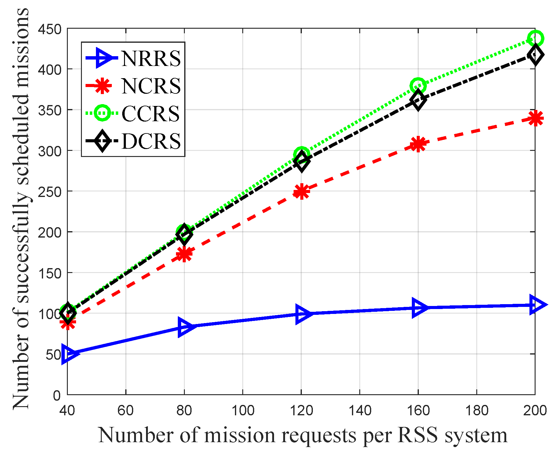
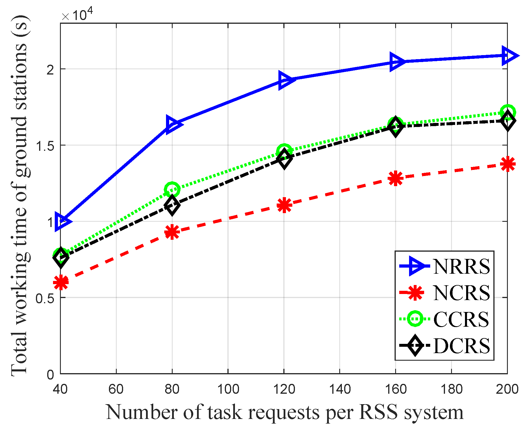
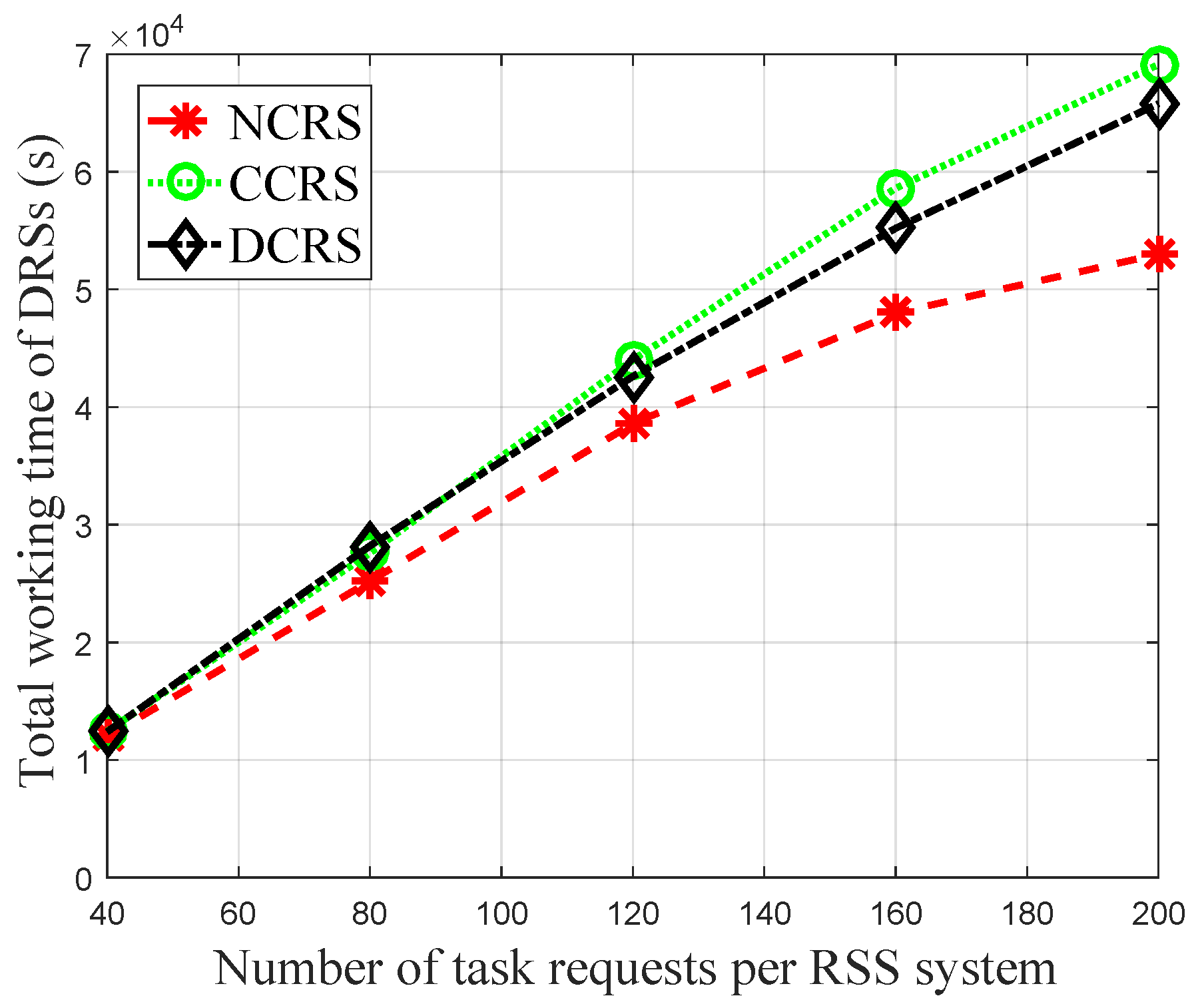
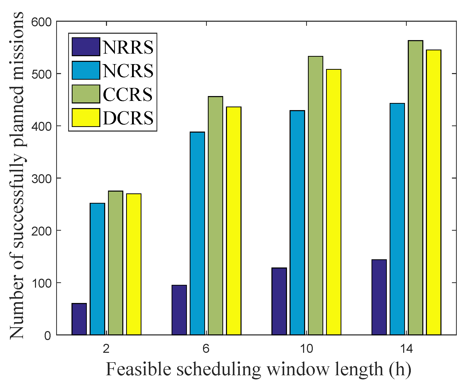
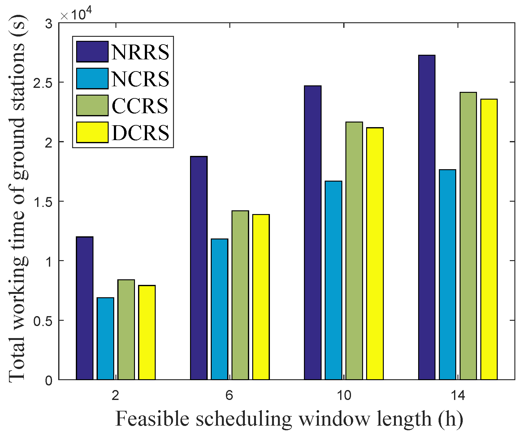
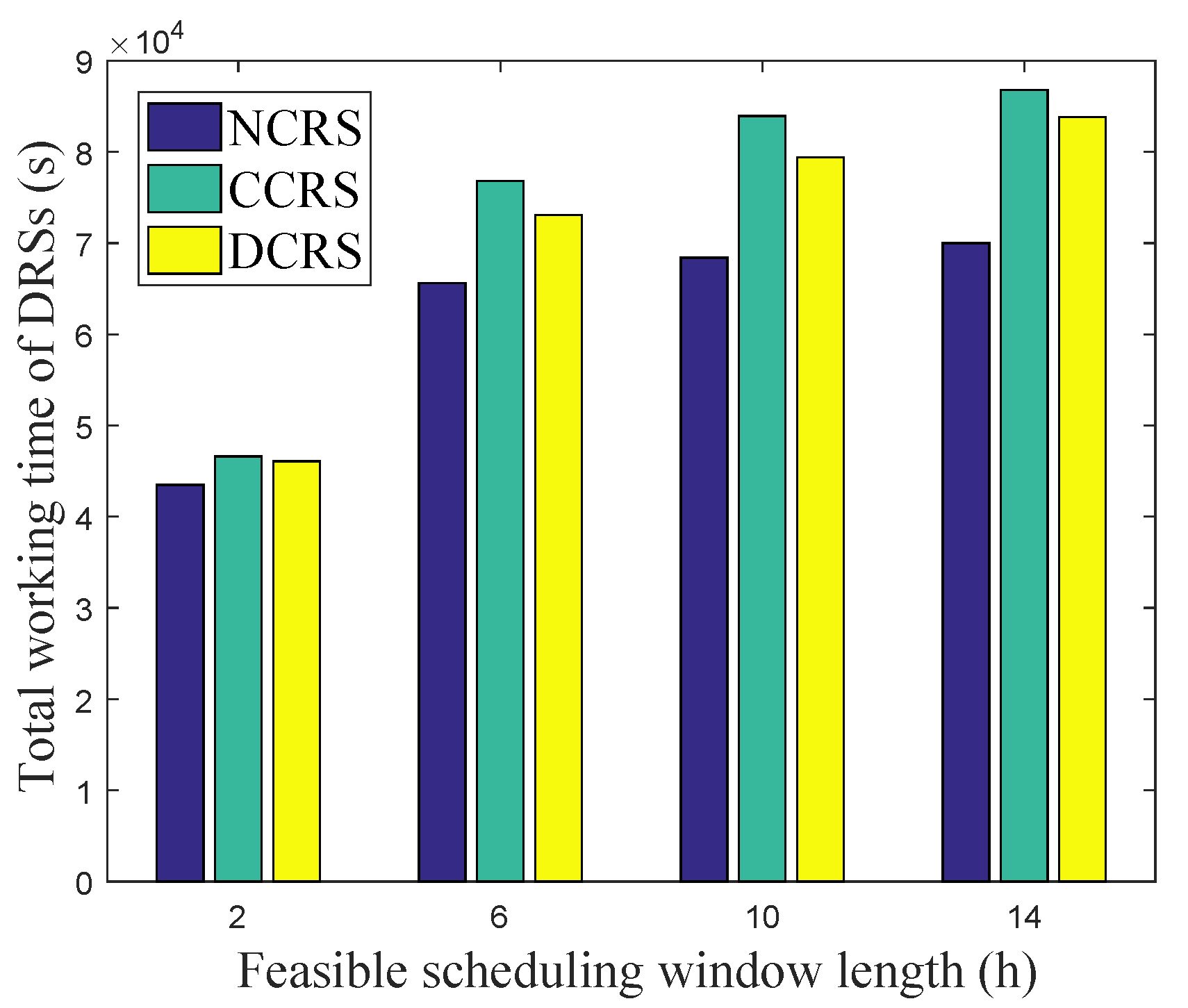
We conducted two groups of simulation experiments. The first group of simulation experiments compares the performance of different schemes with increasing mission numbers. The results of the first group of simulation experiments are shown in Figure 3, Figure 4 and Figure 5, which, respectively, investigate the number of successfully scheduled missions, total working time of the ground stations, and total working time of the DRSs. The first group of simulation experiments compares the performance of different schemes with increasing mission numbers. The second group of simulation experiments compares of different schemes with varying the length of feasible scheduling window (i.e., the difference value between the earliest start time and latest end time of missions). Specifically, we fix the number of mission requests to be 200 and set the feasible scheduling windows to be 2, 6, 10, and 14 h. The results of the second group of simulation experiments are shown in Figure 6, Figure 7 and Figure 8, which, respectively, investigate the number of successfully scheduled missions, total working time of the ground stations, and total working time of the DRSs.

5.2. Results Analysis and Discussion

We can observe from Figure 3 that the proposed DCRS algorithm performs much better than the NRRS and NCRS schemes and close to the CCRS scheme in terms of the number of completed missions. To be specific, the maximum performance between the proposed algorithm and the CCRS scheme is no more than 6%. That is to say, the proposed algorithm performs closed to the ideal centralized benchmark scheme via a distributed manner. What is more, there is an obvious gap between the NRRS scheme and the other three schemes with the support of DRS system, which verifies the importance of the relay resource. Moreover, our algorithm can achieve about 24% performance gain from NCRS, which mainly comes from the advantages of coordinated scheduling of the resources of RSS systems and the DRS system.
To further discuss the source of the performance gain of the proposed algorithm, the total working time of the ground stations and DRSs of different schemes are investigated from Figure 4 and Figure 5. Through comparing the two figures, it can be found that most (more than 80%) of the observed data are downloaded through DRSs for the proposed DCRS scheme, and NCRS and CCRS are nearly so.
More specifically, the NRRS has the largest ground station working time, while the NCRS has the least, as shown in Figure 4. Moreover, the total working time of ground stations under the CCRS and DCRS is very close. This is because under the NRRS scheme, only ground stations can be used to download acquired data. NCRS always overestimate the relay resource that can be used due to lack of coordination among RSS systems and the DRS system. As we can observe from Figure 5, the total DRS working time of proposed DCRS algorithm is 20% larger than NCRS scheme, and it is close to that of CCRS. This is because in the second stage of NCRS, collision of the relay resources may be raised among the RSS systems due to the lack of coordination. Therefore, compared with NCRS, the proposed DCRS gains the resource utilization improvements of both ground stations and DRSs from the advantage of coordination.
Figure 6 depicts the number of successfully scheduled missions with increasing length of feasible scheduling window. It can be observed that the performance of the proposed DCRS scheme is very close to the CCRS scheme for the missions with either short or long feasible scheduling windows. The gain of the proposed DCRS scheme compared to the NCRS scheme increases with feasible scheduling window length. Moreover, compared with the nearly linear increase in the NRRS scheme, the growth rate of DCRS slows down when the length of the feasible scheduling window becomes large.
To further dig up the philosophy behind the performance of different lengths of feasible scheduling windows, we investigate the total working time of the ground stations and DRSs with varying lengths of feasible scheduling windows, which are depicted in Figure 7 and Figure 8. As we can see, the working time of ground stations increases approximately linearly with the length of feasible scheduling windows, while the growth working time of DRSs is small, especially when the feasible scheduling window is long. This is because for the missions downloaded through ground stations, both observation and transmission may need to wait a long time for the RSS to fly above the observation object/ground station. In comparison, for the missions downloaded through DRSs, only the observation process may require a long time, because an RSS is visible to at least one DRS most of the time. Moreover, we can observe that the improvement of the proposed algorithm compared to NCRS increases with the feasible scheduling window length in both Figure 7 and Figure 8. This is because the longer the feasible scheduling window, the larger the degree of freedom for resource allocation. With the coordination of the DRS systems and RSS systems, the DCRS scheme can well utilize the degree of freedom to avoid the collisions of relay resources, while NCRS cannot due to the lack of global information.

6. Conclusions

This paper studies a distributed resource scheduling method to realize the coordination of space–ground multiresources for remote sensing missions. Compared with the centralized resource scheduling method, our method requires no extra coordination center added in the heterogeneous satellite systems. Moreover, it only requires very limited link scheduling information interchange among different satellite systems. Other local information is well-preserved. Therefore, the proposed method is much easier to apply to real systems than centralized coordinated scheduling methods. Simulation results shows that the number of completed missions of the proposed algorithm is improved about 24% compared with NCRS, and it achieves no less than 96% of the centralized coordinated scheduling algorithm. However, as the proposed algorithm is realized by iteration, it requires more computation time and times of information exchanging among the RRS and DRS systems than the noncoordinated scheduling algorithm and centralized coordinated scheduling algorithm. Therefore, it is only suitable for the offline schedule of the nonemergency missions, which can be planned in advance by the OCCs on the ground, and cannot be employed in online schedules for emergency missions. In our future work, we will study the distributed online coordinated scheduling algorithm for emergency remote sensing missions.

Author Contributions

Conceptualization, R.L.; methodology, R.L. and W.W.; simulation, X.D.; validation, W.G.; formal analysis, R.L. and W.W.; writing—original draft preparation, X.D.; writing—review and editing, R.L., W.W. and W.G.; visualization, X.D.; supervision, W.G. All authors have read and agreed to the published version of the manuscript.

Funding

This research was funded by the National Natural Science Foundation of China (No. 62001349), Natural Science Basic Research Program of Shaanxi (No. 2023-JC-YB-566, No. 2023-JC-YB-542), China Postdoctoral Science Foundation (No. 2018M633462), Key Research and Development Program in Shaanxi Province of China (No. 2021GY-066), Young Talent fund of University Association for Science and Technology in Shaanxi, China (No. 20200112), Postdoctoral Foundation in Shaanxi Province of China (No. 2018BSHEDZZ47).

Data Availability Statement

No new data were created or analyzed in this study.

Conflicts of Interest

The authors declare no conflict of interest.

References

  1. Wu, X.; Yang, Y.; Sun, Y.; Xie, Y.; Song, X.; Huang, B. Dynamic regional splitting planning of remote sensing satellite swarm using parallel genetic PSO algorithm. Acta Astronaut. 2023, 204, 531–551. [Google Scholar] [CrossRef]
  2. Liu, R.; Wu, W.; Yang, Q.; Zhou, D.; Zhang, W. Exploring the information capacity of remote sensing satellite networks. IEEE Access 2020, 8, 34056–34070. [Google Scholar] [CrossRef]
  3. Katona, Z.; Gräßlin, M.; Donner, A.; Kranich, N.; Brandt, H.; Bischl, H.; Brück, M. A flexible LEO satellite modem with Ka-band RF frontend for a data relay satellite system. Int. J. Satell. Commun. Netw. 2020, 38, 301–313. [Google Scholar] [CrossRef]
  4. Zhou, D.; Sheng, M.; Li, J.; Han, Z. Aerospace Integrated Networks Innovation for Empowering 6G: A Survey and Future Challenges. IEEE Commun. Surv. Tutor. 2023, 25, 975–1019. [Google Scholar] [CrossRef]
  5. Wu, G.; Liu, J.; Ma, M.; Qiu, D. A two-phase scheduling method with the consideration of task clustering for earth observing satellites. Comput. Oper. Res. 2013, 40, 1884–1894. [Google Scholar] [CrossRef]
  6. Wang, P.; Reinelt, G.; Gao, P.; Tan, Y. A model, a heuristic and a decision support system to solve the scheduling problem of an earth observing satellite constellation. Comput. Ind. Eng. 2011, 61, 322–335. [Google Scholar] [CrossRef]
  7. Du, Y.; Wang, T.; Xin, B.; Wang, L.; Chen, Y.; Xing, L. A data-driven parallel scheduling approach for multiple agile earth observation satellites. IEEE Trans. Evol. Comput. 2019, 24, 679–693. [Google Scholar] [CrossRef]
  8. Zhu, W.; Hu, X.; Xia, W.; Sun, H. A three-phase solution method for the scheduling problem of using earth observation satellites to observe polygon requests. Comput. Ind. Eng. 2019, 130, 97–107. [Google Scholar] [CrossRef]
  9. Zhou, D.; Sheng, M.; Liu, R.; Wang, Y.; Li, J. Channel-aware mission scheduling in broadband data relay satellite networks. IEEE J. Sel. Areas Commun. 2018, 36, 1052–1064. [Google Scholar] [CrossRef]
  10. Chen, X.; Li, X.; Wang, X.; Luo, Q.; Wu, G. Task scheduling method for data relay satellite network considering breakpoint transmission. IEEE Trans. Veh. Technol. 2020, 70, 844–857. [Google Scholar] [CrossRef]
  11. Song, Y.; Xing, L.; Wang, M.; Yi, Y.; Xiang, W.; Zhang, Z. A knowledge-based evolutionary algorithm for relay satellite system mission scheduling problem. Comput. Ind. Eng. 2020, 150, 106830. [Google Scholar] [CrossRef]
  12. Wang, Y.; Sheng, M.; Zhuang, W.; Zhang, S.; Zhang, N.; Liu, R.; Li, J. Multi-resource coordinate scheduling for earth observation in space information networks. IEEE J. Sel. Areas Commun. 2018, 36, 268–279. [Google Scholar] [CrossRef]
  13. Liu, R.; Li, J.; Ji, X.; Wu, W.; Zhou, D.; Zhang, Y. Two-Stage Task Planning Based on Resource Interchange in Space Information Networks. In Proceedings of the International Conference on Communications and Networking in China, Hangzhou, China, 20–21 November 2020; Springer: Berlin/Heidelberg, Germany, 2020; pp. 644–659. [Google Scholar]
  14. Waiming, Z.; Xiaoxuan, H.; Wei, X.; Peng, J. A two-phase genetic annealing method for integrated Earth observation satellite scheduling problems. Soft Comput. 2019, 23, 181–196. [Google Scholar] [CrossRef]
  15. Meng, X.; Wu, L.; Yu, S. Research on resource allocation method of space information networks based on deep reinforcement learning. Remote Sens. 2019, 11, 448. [Google Scholar] [CrossRef] [Green Version]
  16. Kaslow, D. Planning and scheduling of earth observing satellites. In Proceedings of the 2007 IEEE Aerospace Conference, Big Sky, MT, USA, 3–10 March 2007; IEEE: New York, NY, USA, 2007; pp. 1–12. [Google Scholar]
  17. Klemich, K.S.; Cerrone, G.; Heinen, W. Earth observation mission planning. In The FLP Microsatellite Platform; Springer: Berlin/Heidelberg, Germany, 2016; pp. 467–480. [Google Scholar]
  18. Wang, P.; Zhang, X.; Zhang, S.; Li, H.; Zhang, T. Time-expanded graph-based resource allocation over the satellite networks. IEEE Wirel. Commun. Lett. 2018, 8, 360–363. [Google Scholar] [CrossRef]
  19. Liu, R.; Sheng, M.; Lui, K.S.; Wang, X.; Wang, Y.; Zhou, D. An analytical framework for resource-limited small satellite networks. IEEE Commun. Lett. 2015, 20, 388–391. [Google Scholar] [CrossRef]
  20. Ju, Y.; Chen, Y.; Cao, Z.; Liu, L.; Pei, Q.; Pei, Q.; Xiao, M.; Ota, M.; Dong, M.; Leung, V.C.M. Joint secure offloading and resource allocation for vehicular edge computing network: A multi-agent deep reinforcement learning approach. IEEE Trans. Intell. Transp. Syst. 2023, 24, 5555–5569. [Google Scholar] [CrossRef]
  21. Wang, L.; Jiang, C.; Kuang, L.; Wu, S.; Huang, H.; Qian, Y. High-efficient resource allocation in data relay satellite systems with users behavior coordination. IEEE Trans. Veh. Technol. 2018, 67, 12072–12085. [Google Scholar] [CrossRef]
  22. Zhu, Y.; Sheng, M.; Li, J.; Zhou, D.; Han, Z. Modeling and performance analysis for satellite data relay networks using two-dimensional markov-modulated process. IEEE Trans. Wirel. Commun. 2020, 19, 3894–3907. [Google Scholar] [CrossRef]
  23. Bertsekas, D.P. Nonlinear programming. J. Oper. Res. Soc. 1997, 48, 334. [Google Scholar] [CrossRef]
  24. Garey, M.R.; Johnson, D.S. Computers and intractability: A Guide To The Theory of NP-Completeness; W. H. Freeman: New York, NY, USA, 1979. [Google Scholar]
  25. Boyd, S.; Parikh, N.; Chu, E.; Peleato, B.; Eckstein, J. Distributed optimization and statistical learning via the alternating direction method of multipliers. Found. Trends® Mach. Learn. 2011, 3, 1–122. [Google Scholar]
  26. Leinonen, M.; Codreanu, M.; Juntti, M. Distributed joint resource and routing optimization in wireless sensor networks via alternating direction method of multipliers. IEEE Trans. Wirel. Commun. 2013, 12, 5454–5467. [Google Scholar] [CrossRef]
  27. Tabrizi, H.; Peleato, B.; Farhadi, G.; Cioffi, J.M.; Aldabbagh, G. Spatial reuse in dense wireless areas: A cross-layer optimization approach via ADMM. IEEE Trans. Wirel. Commun. 2015, 14, 7083–7095. [Google Scholar] [CrossRef]
  28. Boyd, S.; Boyd, S.P.; Vandenberghe, L. Convex Optimization; Cambridge University Press: Cambridge, UK, 2004. [Google Scholar]
Figure 1. Space–ground coordination network.
Remotesensing 15 03362 g001
Figure 2. Time-expanded graph.
Remotesensing 15 03362 g002
Figure 3. Number of successfully scheduled missions versus the number of mission requests per RSS system.
Remotesensing 15 03362 g003
Figure 4. Total working time of the ground stations versus the number of mission requests per RSS system.
Remotesensing 15 03362 g004
Figure 5. Total working time of the DRSs versus the number of mission requests per RSS system.
Remotesensing 15 03362 g005
Figure 6. Number of successfully scheduled missions versus the length of feasible scheduling window.
Remotesensing 15 03362 g006
Figure 7. Total working time of the ground stations versus the length of feasible scheduling windows.
Remotesensing 15 03362 g007
Figure 8. Total working time of the DRSs versus the length of feasible scheduling windows.
Remotesensing 15 03362 g008
Disclaimer/Publisher’s Note: The statements, opinions and data contained in all publications are solely those of the individual author(s) and contributor(s) and not of MDPI and/or the editor(s). MDPI and/or the editor(s) disclaim responsibility for any injury to people or property resulting from any ideas, methods, instructions or products referred to in the content.