Abstract
High-accuracy Low Earth Orbit (LEO) satellite clock and orbital products are preconditions to realize LEO augmentation for high-accuracy GNSS-based positioning on the ground. There is a high correlation between the orbit and clock parameters in the kinematic Precise Orbit Determination (POD) process. While future LEO satellites are planned to be equipped with better clocks, the benefits of modeling high-stability LEO satellite clocks are not yet thoroughly investigated, particularly when mid- to long-term systematic effects induced by the complex LEO relativistic effects and the external environment remain in the clocks. Through clock modeling, this study attempts to reduce not only the short-term noise of radial kinematic orbits, but also mis-modeled effects caused by, e.g., real-time GNSS orbital and clock errors. To explore the benefits of clock modeling, the clocks need to be first detrended by the mid- to long-term systematic effects. While over-detrending limits the orbital improvements, weak detrending would also hamper strong clock modeling and easily lead to performance degradations. A balance between the strengths of the detrending and the model thus needs to be investigated for different clock types. In this study, the Piece-Wise Linear (PWL) model of different time lengths and a 2.5-state filter with different strengths (h values) are tested using real data from GRACE FO-1 with an Ultra-Stable Oscillator (USO) on board. Using the CNES real-time GPS products, it was found that when detrending the clocks with a smoothing window of 300 to 500 s, one could generally expect an improvement larger than 10% in the estimation of radial orbits when applying a PWL model with a length from 300 to 1200 s. Improvements of this size can also be expected when using the 2.5-state model with h−1 (for Flicker Frequency Noise) from 10−28 to 10−30.
1. Introduction
In the next decade, tens of thousands of Low Earth Orbit (LEO) satellites will form a dense network at an orbital height of hundreds of kilometers to over 1000 km above the Earth. This includes satellites launched by companies such as SpaceX and OneWeb primarily for communication/Internet purposes [1]. Other LEO satellite missions such as the Gravity Recovery and Climate Experiment (GRACE) and Sentinel have also existed for decades for scientific and research purposes. In recent years, LEO satellites have been proposed to form new constellations that can augment the positioning service. Moreover, the Kepler system proposed by the German Aerospace Center is planned to comprise 6 LEO satellites and 24 Medium Earth Orbit (MEO) satellites in its constellation [2].
The rapidly increasing number of LEO satellites will benefit Positioning, Navigation and Timing (PNT) service on the ground. It will improve satellite geometry, and, thus, positioning precision. The much stronger signal strength of LEO satellites would possibly enable indoor positioning in the future [3]. The high satellite speed would shorten the convergence time of Precise Point Positioning [4], and may whiten the multipath effects that have been a bottleneck for users in complicated environments [5].
Like GNSS, producing precise orbital and clock products is a precondition to realizing high-accuracy positioning for ground users employing LEO satellites. While the orbital and clock parameters are often estimated together in the least-squares adjustment, the high correlation between them requires further de-correlation through better modeling to separate the two products [6,7]. In the last decades, dynamic models of LEO satellite orbits have been intensively studied [8,9,10]. The reduced-dynamic Precise Orbit Determination (POD) process de-correlates the clocks and the radial orbits, leading to significant precision improvement in the radial orbital component. For the kinematic POD, the radial orbits can be improved by modeling clock errors. Modeling has been attempted for the Ultra-Stable Oscillators (USOs) that were equipped on LEO satellites from missions such as GRACE [11], the GRACE Follow-On (GRACE-FO) [12], and the Sentinel-3 [13]. Yang et al. [7] improved the GRACE B orbits by modeling the USO clock as two-states and three-states in a Kalman filter designed for real-time processing. Zhou et al. [14] improved the GRACE orbits by applying relative constraints between clock errors of subsequent epochs. Weinbach and Schön [15] used the Piece-Wise Linear (PWL) model with a length of 60 s to USO to benefit from its good short-term stability. There, significant improvement was identified in high-pass filtered radial orbits, i.e., in the short-term noise of the orbits.
The LEO clock estimates, however, could suffer from mis-modeled effects such as errors in the GNSS orbits and clocks used for processing. These effects are enlarged in the kinematic mode due to the high correlation between the orbits and clocks. For example, high-precision real-time GNSS products are often used for near-real-time LEO POD [16], introducing mis-modeled effects caused by the estimated real-time GNSS satellite orbital and clock errors. These mid- to long-term effects can be reduced when, e.g., longer PWL can be applied in the clock model. However, the following issues hamper the utilization of such a strong clock model:
- ➢
- The clock stability might not be stable enough for a strong clock model. This problem is partially solved when clocks of better stability, e.g., Hydrogen-Maser (H-Maser) or optical clocks [2], can be used in LEO satellites in the future.
- ➢
- Complex once- and twice-per-revolution effects remain in the LEO clocks due to the low altitude of LEO satellites. These effects cannot be perfectly corrected with the extended formula of the relativistic effects for LEO satellites [17].
- ➢
- Significant long-term systematic effects of a few meters could exist in LEO clocks, suspected to be induced by the external environment. These effects were observed in satellites of GRACE Follow-On, Sentinel 3B and Sentinel-6A [18,19,20].
In many of the previous studies using GRACE data mentioned above, no significant systematic effects were observed in the clocks, as the pre-processed Level 1B observations were used instead of the raw Level 1A observations [21]. The Level 1B observations, however, have a priori corrected the observations with the clock errors obtained in the reduced-dynamic POD (CLK1B). In such a case, one can model, for example, the 24 h clock errors as a linear polynomial and obtain the orbits at the reduced-dynamic level. Figure 1 shows the radial orbital errors of GRACE FO-1 on 14 August 2018 compared to the reference orbits provided by the Jet Propulsion Laboratory (JPL). The final GPS products from the Center for Orbit Determination (CODE) were used for processing [22]. Using Level 1A observations, the red and blue lines illustrate the radial orbital errors in the kinematic (KN) and reduced-dynamic (RD) modes with epoch-wise clock estimation, resulting in Root Mean Square (RMS) of about 3.5 and 1.2 cm, respectively. Using the Level 1B observations, as shown by the green lines, the kinematic orbital errors are reduced to the level of the blue line (RMS: 1.6 cm) by estimating the 24 h clocks just as a linear polynomial, only with the short-term noise increased a bit. In this study, we perform the kinematic POD starting from the raw observations (Level 1A).
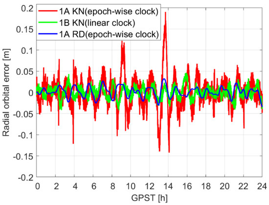
Figure 1.
Radial orbital errors in three modes: kinematic (KN) mode using 1A observations, KN mode with linear model using 1B observations, and Reduced-dynamic (RD) mode using 1A observations, compared to the JPL reference orbits. The data from GRACE FO-1 on 14 August 2018 and CODE final products were used.
2. Research Goal
To explore the benefit of clock modeling, this contribution proposes to detrend the clock estimates first with their mid- to long-term pattern that can be captured by the GNSS estimation. These mid- to long-term patterns include not only the relativistic effects, the significant systematic effects induced by external environments, and the mis-modeled errors induced by the GNSS satellite products, but also the mid- to long-term trend of the frequency oscillator itself. A too-weak detrending would limit the possibility of applying effective clock models, or would easily push different non-clock systematic effects into the orbits. At the same time, a too-strong detrending would remove the systematic behaviors of the frequency oscillator itself and lead to very little improvement through clock modeling. A balance between the strength of the detrending and the clock model is, therefore, to be investigated. In a nutshell, this paper deals with LEO satellite clock modeling for clock estimates containing unignorable systematic effects. This paper attempts to propose reasonable strategies to benefit from the clock stabilities in the presence of these systematic effects and explore improvements in the kinematic orbits using different clock modeling methods.
Different methods were used for clock detrending in previous studies, although not all for LEO satellite clocks. Examples are the detrending of the polynomial and harmonic terms [23], the Lomb-Scargle power spectrum and the continuous wavelet transform used for GNSS satellite clock analysis [24]. In this study, mean values within different lengths of smoothing windows are removed to detrend LEO satellite clocks. In such a way, the strength of the detrending effects can be controlled by varying the length of the smoothing windows.
Two clock models are used for the investigation in this study, i.e., the PWL model of different lengths and a 2.5-state model realized in sequential least-squares adjustment considering different system noise between subsequent epochs of clocks. Real data analysis is performed for the USO clock in GRACE FO-1. In this study, clock modeling is applied to ambiguity-float kinematic POD using real-time GNSS products. The real-time GNSS products were used, as the filter-based clock modeling typically applies to a (near)-real-time POD process. The ambiguity-float kinematic POD is investigated when applying the clock models due to the high correlations between the clocks, the float ambiguities and the radial kinematic orbits. The clock modeling helps with the de-correlation and improves the radial orbits that exhibit the worst accuracy in the three directions within a kinematic POD. In the reduced-dynamic POD, the radial orbits are already largely de-correlated with the clocks by applying dynamic models. In such a case, the clock modeling of, e.g., a USO would have less significant improvements in the radial orbits, especially under the existence of diverse systematic effects.
This paper starts with introducing the processing strategies without and with LEO satellite clock modeling. The potential of kinematic orbital improvement is discussed for different strengths of the clock detrending and clock models, followed by the conclusions.
3. Processing Methods
In this section, the kinematic and reduced-dynamic POD process with epoch-wise clock estimation and applying the PWL and the 2.5-state clock models with relative constraints are introduced.
3.1. POD without Clock Modeling
The LEO satellites can use dual-frequency code and phase GNSS observations assumed to be collected by a receiver on board to compute the satellite position. The Ionosphere-Free (IF) combination is formed to remove first-order ionospheric delays. Considering the fact that the LEO satellites are flying above the troposphere, only the LEO satellite positions (or parameters to derive LEO satellite positions), the LEO satellite clock offsets and the float ambiguity terms (e.g., for satellite ) are to be estimated as unknowns. As such, the expectations of the IF code () and phase () Observed-minus-Computed (O-C) terms can be expressed as:
where is the expectation operator and the variances are given on the right-hand side. The POD process is considered here in two modes: the kinematic and the reduced-dynamic modes. In the former case, contains the 3-dimensional (3D) coordinates of the LEO satellite, denoted as , and the corresponding design matrix () contains the unit vector from the GNSS satellite to the LEO satellite. denotes the speed of light. is with () denoting the frequency . and denote the IF wavelength and the ambiguity (of satellite ), respectively. The denotes the estimable LEO satellite clock offset. The standard deviations of the IF code () and phase () observations are amplified due to the use of IF combination compared to the case when using individual observations, such as the L1-referenced code () and phase standard deviations , which amount to about 0.1 m and 1 mm. An equal weighting is applied in the POD process due to the relatively simple measurement environment of the LEO satellite and the absence of tropospheric delays, as done for the Sentinel satellite [25], the Medium Earth Orbit (MEO) and the Inclined Geosynchronous Orbit (IGSO) satellites of the BeiDou Navigation Satellite System (BDS) [26,27]. The antenna sensor offsets, their phase center offsets and variations of the GNSS and LEO satellites, the phase windups and the general relativistic effects have been corrected in the O-C terms. Note that only the GPS constellation is considered in this study, where the GPS IF code biases are contained in its satellite clock products. By forming the IF combination, 99% of the ionospheric delays that represent its first-order term are removed [28]. High-order terms of the ionospheric delays are ignored in the processing. They are to be considered in the integrity monitoring of the LEO satellite POD [29].
Although the clock modeling is only applied to the kinematic POD in this study, for the reason of comparison, the reduced-dynamic orbits and clocks are computed. In the reduced-dynamic mode, a series of orbital elements are estimated in , denoted in this case as . It contains the six Keplerian elements at the initial state, three time-constant dynamic parameters in the radial (R), along-track (A) and cross-track (C) directions, and a series of stochastic piece-wise constant accelerations within pre-defined time intervals, taken in this study as 6 min each. The stochastic accelerations are constrained to zeros with a standard deviation of . Perturbations such as air drag and solar radiation pressure are largely compensated by time-constant dynamic parameters and stochastic accelerations [30,31]. The design matrix in such a case is denoted as and contains the partial derivatives of the observations with respect to , which can be numerically integrated based on the variational equations [8]. Based on existing dynamic models used for perturbation terms—summarized in Table 1—and the estimated orbital elements, the orbital positions can then be computed at each epoch with numerical integration in the reduced-dynamic mode. The clock offsets of the LEO satellite are typically estimated as independent parameters at each epoch.

Table 1.
Dynamic models used for the perturbation terms in the POD.
3.2. POD with Clock Modeling
For clocks of good stabilities, e.g., the USOs, atomic clocks, or optical clocks that might be installed on future LEO satellites, modeling the clocks is helpful to de-correlate the clock parameters and kinematic radial orbits [7,15], thus improving the orbital accuracy. In this study, two clock models (i.e., the 2.5-state model and the PWL model) are used during the kinematic POD process, which will be described in the following two sections.
3.2.1. 2.5-State Model
As described by Wang and Rothacher [36], the receiver clock biases can be described by a low-order polynomial and a stochastic clock parameter. In this study, a quadratic polynomial consisting of an initial clock offset , a frequency offset and a frequency drift is used to describe the deterministic part of the LEO satellite clock, while a stochastic clock offset is used to capture the remaining stochastic clock behaviors at time point . In the observation model (see Equations (1) and (2)), the LEO satellite clock bias can thus be expressed as follows:
where indicates the time at the start of processing. For simplicity, is expressed as in the following contexts. The IF LEO satellite code bias that is contained in the estimable LEO satellite clock parameter is assumed constant over the processing period.
The one-state relative constraint, as discussed in Wang and Rothacher [36], however, assumes a White Frequency Noise (WFN) of the clocks with the variance of the between-epoch relative constraint linearly increasing with the sampling interval. For other noise types, a two-state model, having both the stochastic clock offset () and a frequency offset () estimated and constrained, would be more appropriate. The frequency drift term (see Equation (3)) is estimated as a constant in the deterministic clock model. This is equivalent to a three-state model with the variance of the relative constraint between frequency drifts of subsequent epochs set to zero. As such, the model introduced in this study is termed a “2.5”-state model. In a least-squares form, the relative constraints can be formulated as:
where denotes the time derivative of . To avoid singularity between and in Equation (3), a weak absolute constraint (set to zero) is additionally applied to with a large standard deviation , e.g., 1 m:
As a constant frequency offset is previously estimated, the initial value is also constrained to zero with a standard deviation , such that:
The variance–covariance matrix for constraint Equations (6)–(9) is given as:
where forms a diagonal matrix using the elements contained in . At epoch , is set to . The variance–covariance matrix of the relative constraints is a function of the noise type, size, and sampling interval . This will be explained later in this section.
Adding the clock constraints is the same as adding the following term to the normal equation matrix for the stochastic clock parameters of epoch and :
where represents the a priori standard deviation of unit weight (on L1), assumed here 1 mm. Based on Equations (4)–(7), the matrix is expressed as:
where denotes the identity matrix with a size of 2. To improve the computational efficiency when solving using the batch least-squares adjustment, a pre-elimination and back-substitution strategy is applied for the epoch-wise clock and orbit parameters considering the relative constraints between subsequent epochs. The case for the one-state clock model [37] is extended here to a two-state model.
As shown in van Dierendonck et al. [38] and Krawinkel and Schön [6], the system noise to be applied between subsequent clock parameters within a Kalman filter differs for different noise types. The Kalman filter, at the same time, can be equivalently expressed in the form of a sequential least-squares adjustment [39] with:
where represents all the O-C terms at epoch , including any absolute constraints on the estimable parameters, e.g., the weak absolute constraints on the stochastic clock parameters (Equations (6) and (7)). describes the observation model of all estimable parameters at epoch , and the corresponding variance–covariance matrix of the observations is denoted as . Among all the estimable parameters, the ones to be temporally updated are contained in the vector . The estimated at , multiplied by the transition matrix , are treated as pseudo-observations for these parameters at . denotes the variance–covariance matrix of at , which is a fully populated variance–covariance matrix for all the time-updated unknowns. is the system noise for updating from epoch to . In , one distinguishes further between the clock parameters () and other parameters to be updated (), e.g., the phase ambiguities. The clock parameters contain, in our case, the three polynomial coefficients that are constrained as constants in time, and the stochastic clock offset and frequency offset , which need to be updated with their clock system noise . The transition matrix and the variance–covariance matrix for the total system noise can thus be expressed as:
for which and denote the transition matrix and process noise matrix for , respectively. denotes the ()-th element of the matrix for clock system noise , where here. As the sequential least-squares adjustment can also be formulated in the form of a batch least-squares [40], the matrix for the clock system noise replaces in Equation (8). The standard deviation for the initial absolute constraint of the frequency offset, i.e., at (see Equation (7)), is set to . The clock model can thus be realized using a batch least-squares adjustment or a real-time filter based on sequential least-squares. In this study, the former case is applied for the tests presented due to the clock detrending method that will be discussed in Section 4. It is noted that Gaussian distribution, as assumed in this study, may not perfectly describe the observation noise and the estimation errors. This should be considered in the integrity monitoring of the POD of LEO satellites.
Taking the WFN, the Flicker Frequency Noise (FFN), and the Random-Walk Frequency Noise (RWFN) for the LEO satellite clocks as examples, Table 2 gives their slopes in terms of the Allan deviation [41] and the elements in the variance–covariance matrix for the relative constraints (, and ), as well as the () coefficients in , and . The coefficients are constant, where their amplitudes are related to the clock stabilities.

Table 2.
Characteristics of clock noise types (WFN, FFN, RWFN).
To give an example of the effects when applying the 2.5-state model of different strengths, Figure 2 shows simulation test results for the clock errors estimated in the kinematic POD for two cases when applying and not applying the given clock model. The observation geometry of GRACE FO-1 on 14 August 2018 was used for the simulations. Only the noise and real-time GPS orbital and clock errors are considered in the O-C terms. The latter term was obtained by comparing the real-time GPS products between the French National Centre for Space Studies (CNES) [42] and the final products from the CODE, with the clock products re-referenced to those of the final CODE products. The standard deviation of the phase and code noise is set to 0.001 m and 0.1 m, respectively. The clock model for a WFN is applied, with (see Figure 2) varying from to s. The increasing strength in the clock model directly leads to an increasing smoothing effect of the clock errors. The peak in the green line at around 00:51 and 17:22 are caused by data gaps and looser constraints. After applying the clock models, the short-term stability in the Modified Allan Deviation (MDEV) is reduced, with the reduction extended to the mid-term stability when further decreasing the value.
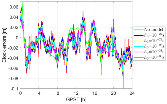
Figure 2.
Smoothing effect of the LEO satellite clock errors for GRACE FO-1 applying the 2.5-state model for WFN on 14 August 2018.
3.2.2. Piece-Wise Linear Model
The PWL model estimates the clocks with linear polynomials of a pre-defined time interval [15]. It can be expressed as follows:
where and denote the clock bias at the knot point in the PWL model before and after , respectively. is the time interval from the knot point before to the epoch . The estimable parameters are clocks at a series of knot points separated by . The determined factor of the PWL model is the time interval .
Using the same satellite geometry as in Section 3.2.1 and considering the same noise and mis-modeled effects, Figure 3 illustrates the smoothing effect in the kinematic clock estimates, applying the PWL model of different lengths. It can be observed that an increasing PWL length corresponds to a reduced -value in the 2.5-state model as shown in Figure 2. Unlike the 2.5-state model that constrains the clocks, also weakly in the long term, the PWL model puts infinitely strong constraints on clocks (above the linear polynomial) within each pre-defined . Applying the PWL model reduces the short-term stability of the estimated clock errors by adding an infinitely strong constraint for each PWL interval, i.e., estimated as linear polynomials.
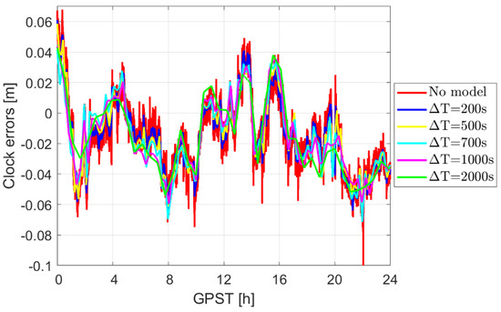
Figure 3.
Smoothing effect of the clock errors for GRACE FO-1, applying the PWL model on 14 August 2018.
To illustrate the different effects of the PWL model and the 2.5-state model, Figure 4 shows the estimated clock errors when applying the 2.5-state model with s and the PWL model with of 2000 s. Similar to Figure 2 and Figure 3, the satellite geometry of GRACE FO-1 on 14 August 2018 was used for the simulations, considering only the observation noise and the GPS orbital errors. As shown in Figure 4, a small value ( as an example) in the 2.5-state model smooths the clock estimates in the long term, while a long PWL length extends the length of each period with infinite strong constraint, i.e., the length of the piece-wise linear polynomials. In other words, the small value, i.e., a strong 2.5-state model, constrains and smooths the clock estimates from the short to long term. In contrast, a strong PWL model, i.e., a long PWL length , assumes the clocks within each PWL interval to be a linear polynomial but limits these constraints within each PWL interval.
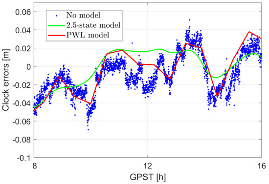
Figure 4.
Modeling the 30 s clock estimates with the 2.5-state model ( s) and the PWL model with of 2000 s.
4. Test Results
Real data are used for the POD and clock modeling of the USO onboard LEO satellite (the GRACE Follow-on satellites). This section starts with the introduction of the test description, followed by the POD results using the two investigated clock modeling methods. A summary is given at the end of the section.
4.1. Test Description
Using real observation data from GRACE Follow-on satellites as an example, this section explores the benefits of the two clock modeling approaches (the 2.5-state and the PWL) on orbital improvements. Compared with most LEO satellites equipped with Oven-Controlled Crystal Oscillators (OCXOs) and Temperature-Controlled Crystal Oscillators (TCXOs), the GRACE Follow-on satellites are equipped with USOs that have good short- to mid-term stabilities. This is helpful for analyzing the external systematic effects contained in the clock estimates, as well as the corresponding effects of the detrending and the clock modelling.
The CNES real-time GPS products are used for processing, which also introduces mis-modeled effects into the observations. The CNES real-time GPS products were used as a “quicker” option compared to the final products from different analysis centers, which normally have a latency of about two weeks. In this section, the need for clock detrending will be discussed, and proper model strength will be employed when considering the USO clocks to ensure significant orbital improvements.
As mentioned earlier, the clock and orbital parameters are highly correlated with each other in the estimation process, and one can benefit from better clock stability. However, in addition to clock stability, the onboard LEO satellite clocks are influenced by other systematic effects, which could hamper strong clock modeling. Relativistic effects in the LEO satellites, for example, are more complex than those of the GNSS satellites due to the much lower altitudes of LEO satellites. As shown in Larson et al. [17], even with the effects of the Earth oblateness considered in the model, the once-per-revolution (1/rev) and twice-per-revolution (2/rev) terms still could not be perfectly corrected, leading to increased power in the 1/rev term using GRACE A and B, as examples. Moreover, large half-day and quarter-day systematic effects from a few meters up to ten meters are also observed in satellites such as GRACE Follow-on and Sentinel-3B [18] with slightly varying periods and amplitudes that could be related to external effects such as temperature.
Using the raw data from GRACE FO-1 on 14 August 2018 from the JPL at Level 1A [21], the MDEVs of the clock estimates in the kinematic and reduced-dynamic modes are illustrated in the left panel of Figure 5, applying epoch-wise clock estimation. The MDEV presents the stability of the clock estimates at different averaging times, with detailed explanations given in [43]. A quadratic polynomial was detrended before the calculation of MDEVs. The epochs having less than five IF phase/code observations were not considered, as these will not typically result in good positioning. To guarantee a stable time reference, the GPS clocks of the CNES real-time products are re-referenced to a stable time scale, e.g., by using a selected H-Maser in the CODE final clocks on the same day here or directly using a reference receiver linked to a highly stable time reference [44]. Compared to the expected lab behavior of a good USO, as shown by the green dashed line, the short-term noise (before about 100 s) of the blue and red lines are mainly driven by the GNSS observations noise, while the mid- to long-term behaviors are overlapped effects of the clock instability itself, the mis-modeled real-time GPS orbital and clock errors, the relativistic effects and the significant systematic effects caused by the external environment [18].
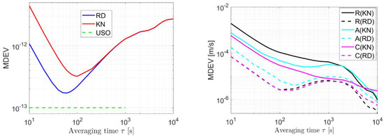
Figure 5.
MDEVs of the clock estimates (left) and the orbital errors (right) in the kinematic (KN) and reduced-dynamic (RD) modes using the data from GRACE FO-1 and the CNES real-time GNSS products on 14 August 2018. Quadratic polynomial was detrended before calculating the MDEVs.
Correspondingly, the MDEVs of the orbital errors using the CNES real-time products are illustrated in the right panel of Figure 5 in the radial I, along-track (A) and cross-track (C) directions for both the kinematic (KN) and reduced-dynamic (RD) modes. For model consistency, the reduced-dynamic orbits computed using the CODE final products, applying the model described in Section 3.1, were taken as the reference orbits. The mis-modeled effects of the real-time GNSS products are visible in the right panel of Figure 5 as the arches from about 100 s to a few thousand seconds, which are caused by the real-time GPS orbital and clock errors, as well as possible model deficiencies in the reduced-dynamic mode. From the right panel of Figure 5, it can also be observed that the differences between the kinematic orbits (solid lines) and the reduced-dynamic orbits (dashed lines) are not only reflected in the increased short-term noise, but also in the enlarged projection of the mis-modeled effects on the orbits. In the kinematic mode, the radial orbital errors (solid black line) are higher than those in the other two directions due to the higher correlation between the radial orbits and the clocks in the estimation process.
As it is challenging to perfectly correct the 1/rev and 2/rev effects and the significant systematic effects induced by the external environment based on existing physical models, and to possibly explore the benefits of the clock modeling, the mid- to long-term clock trends that can be captured by POD and clock estimation using the GNSS observations are a priori corrected in the O-C terms. Figure 6 shows the kinematic clocks detrended first with only a quadratic polynomial (red lines) and next with smoothed trends using mean values within a smoothing window . From Figure 6 it can be observed that the mid- to long-term systematic effects can be stepwise removed by decreasing the smoothing windows. However, it should be noted that the detrended term also includes the projection of the mis-modeled effects, which influence not only the clocks but also the orbital estimates. Decreasing the smoothing window could allow for applying a stronger clock model, but it does not necessarily benefit the estimated orbits more, as the correlated clock errors might be partially removed by the detrending process as well. As such, a balance needs to be investigated to maximize the actual improvement in the orbit estimation.
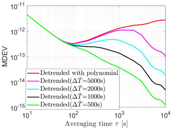
Figure 6.
MDEVs of the kinematic clock estimates detrended with and without the smoothed trends.
In this section, the CNES real-time products and the USO in the GRACE FO-1 are used as an example to explore the benefits of the two different clock models (PWL and the 2.5-states models) in the kinematic POD.
4.2. PWL Model
Applying the PWL clock model with different lengths from 300 to 3000 s (for each linear polynomial), the Root Mean Square (RMS) of the radial orbital errors is shown in Figure 7, detrended using different smoothing windows . From Figure 7 it can be observed that when detrending only with a quadratic polynomial (the yellow lines), applying the PWL model with a length longer than 400 s easily leads to large degradations in the orbital elements. When detrended with more systematic effects, as shown by the other colored lines, there is a potential to improve the orbital elements further. In general, a smoothing window of 500 s (see the magenta lines) provides a proper solution for the modelling without large degradation, even at a PWL length of 1400 s, and, at the same time, delivers significant improvement in the radial orbits, e.g., 16% at a PWL length of 1000 s. It is noted that the 3–4 cm RMS of the radial orbital was achieved in the ambiguity-float kinematic POD method using real-time GNSS products.
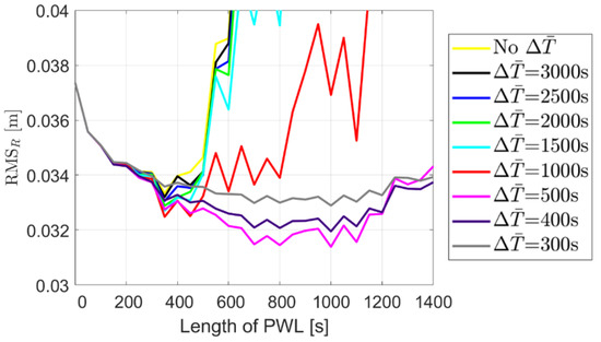
Figure 7.
RMS of the kinematic orbital errors in the radial direction applying the PWL clock model of different lengths. The x-value of 0 represents the case of epoch-wise clock estimation.
The MDEVs of the radial orbital errors are shown in the left panel of Figure 8 for a smoothing window of 500 s, as an example, and PWL lengths of 400 s, 1000 s and 1400 s. Despite the reduced short-term noise for all three PWL lengths, slight differences can be observed in the medium to long term around an averaging time of 1000 s. While the benefits in orbital improvement are not yet fully shown when applying a PWL of 400 s (the yellow line), a too-strong constraint with a PWL of 1400 s begins to degrade the orbits around 1000 s (the black line). In the right panel of Figure 8, the PWL model of 1000 s is applied when detrending the clocks with a smoothing window () of 300 s, 500 s and 1000 s. It can be observed that detrending the clocks using a smoothing window () of 1000 s does not allow for a PWL () of 1000 s and pushes the remaining mid-term clock systematic effects into the orbits. Further smoothing the clocks with a window of 500 s (or less) allows for such a PWL length. However, over-smoothing with, e.g., a window of 300 s also removes too many mis-modeled effects in the clocks, which offers less chance to improve the orbits through de-correlation (see the yellow line above the green line in the right panel of Figure 8).
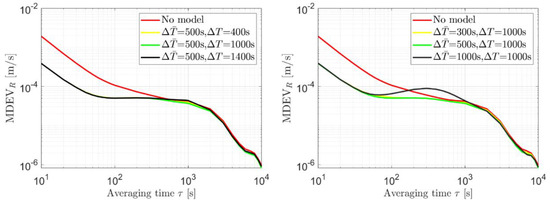
Figure 8.
MDEV of the radial orbital errors for a smoothing window of 500 s in the clock detrending (left) and a PWL length of 1000 s (right).
Figure 9 illustrates the orbital errors when not applying (shown in red) and applying the PWL clock model that delivers the largest improvement in each direction (in yellow). For comparison purposes, the reduced-dynamic orbits are illustrated with blue lines as well. It can be observed that applying the PWL does not only reduce the noise but also helps to reduce the enlarged mis-modeled effects in the kinematic mode.
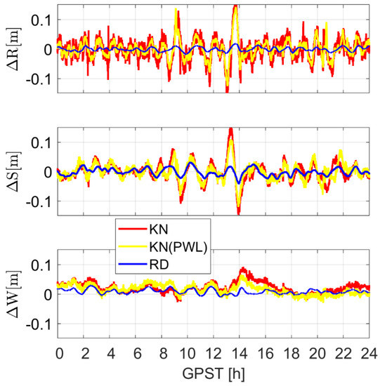
Figure 9.
Radial (R), along-track (S) and cross-track (W) orbital errors in the reduced-dynamic (RD) mode and kinematic (KN) mode when not applying and applying the best PWL model for each direction.
The RIS improvemeIts in the orbits are liIted in Table 3 for different smoothing windows and PWL lengths. It can be observed that a smoothing window of 300 to 500 s generally allows for improvements of radial orbits of more than 10% by applying a PWL length from 400 to 1200 s. Increasing the smoothing window to over 1000 s allows for only a small PWL length, and degradations (see negative values) could be resulted in large PWL lengths above 1000 s. A summary will be given in Section 4.4, together with the results of the 2.5-state model.

Table 3.
Orbital improvements (in percentages) for different smoothing windows and PWL lengths for USO. The improvements in the radial, along-track and cross-track directions are separated by “/”.
4.3. 2.5-State Model
Following the model described in Section 3.2.1, the 2.5-state clock model using FFN is applied to the USO clock used in GRACE FO-1. For the short-term stability of , according to the last column of Table 2, the should amount to about . After the detrending with different smoothing windows, the is tested from down to a small value of and the influence of this change on the orbits is assessed.
Taking the radial direction as an example, Figure 10 shows the RMS of the orbital errors applying the 2.5-state model for FFN with different values of, after being detrended with clocks of different smoothing windows. It can be observed that a rather significant improvement of about 19% can be obtained in the radial direction for a smoothing window of 1000 s at of (see the red line). Further decreasing the smoothing window would lead to smaller improvement and give a “safer” solution to avoid large degradations, even with a very small .
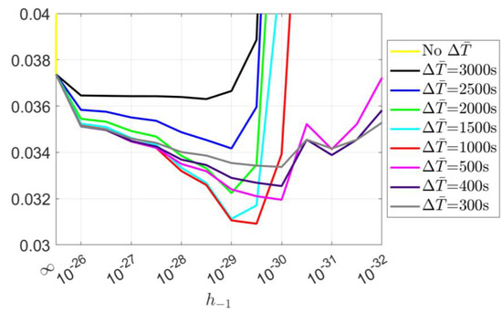
Figure 10.
RMS of the radial kinematic orbital errors applying the 2.5-state model for FFN with different values. The on the x-axis represents the case of epoch-wise clock estimation.
Figure 11 shows the MDEVs of the orbital errors with and without the 2.5-state model for FFN having an of . The clocks were detrended with a smoothing window of 1000 s. For the radial components (see the red and magenta lines), it can be observed that the clocks are stabilized in both the short and the long term, namely with both the noise and mis-modeled effects reduced. In the along-track and cross-track directions, the improvement in the short-term noise is limited. In the long term, however, we observe stabilized mis-modeled effects compared to the case of epoch-wise clock estimation.
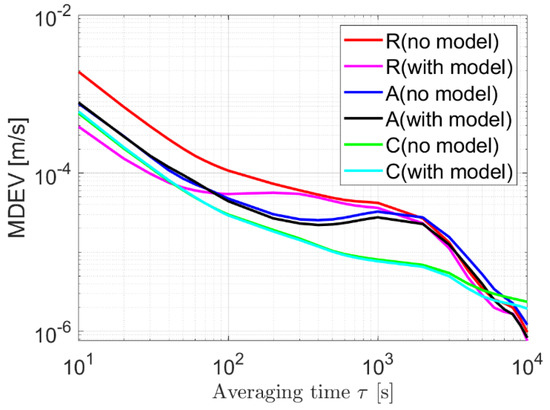
Figure 11.
MDEVs of the orbital errors without clock model and with the 2.5-state model for FFN with an of . The clocks were detrended with a smoothing window of 1000 s before modeling.
The orbital improvements applying different values and smoothing windows are listed in Table 4. In general, by applying the 2.5-state model with an value of to after detrending the clocks with a window of 300 to 500 s, one could improve the radial orbits by about 10% or more. After applying a smoothing window equal or larger than 2000 s, degradations could be resulted in the orbits when the value is smaller than .

Table 4.
Orbital improvements (in percentages) for different smoothing windows and for USO. The improvements in the radial, along-track and cross-track directions are separated by “/”.
4.4. Summary for Improvement in the Radial Orbits
Figure 12 shows the improvements in the radial orbits for between 0% and 5% (grey), between 5% and 10% (yellow), between 10% and 15% (green) and around or above 15% (red), applying the PWL and the 2.5-state models. Data from GRACE FO-1 on 14 August 2018 were used for the analysis. In general, by detrending the clocks with a smoothing window of 300 s to 500 s, improvement around or over 10% can be expected in the radial orbits when applying the PWL model with a length of 300 s to 1200 s, or using the 2.5-state model (for FFN) with a from to . The RMS of the radial orbital errors before and after applying the clock models are given in Table 5 and Table 6.
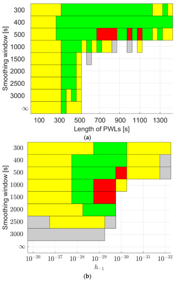
Figure 12.
Improvements in the radial orbits when applying (a) the PWL model and (b) the 2.5-state model to the USO in GRACE FO-1 on 14 August 2018 using the CNES real-time products. The grey areas denote improvement between 0% and 5%, the yellow areas between 5% and 10%, the green areas between 10% and 15%, and red areas around or above 15%.

Table 5.
RMS of the radial orbital errors for the suggested smoothing windows and PWL lengths.

Table 6.
RMS of the radial orbital errors for the suggested smoothing windows and .
If the projected mis-modeled effects are of different sizes, the orbital improvements could exhibit slight differences even when applying the same clock models. As examples, real data from GRACE FO-1 and another satellite GRACE FO-2 on 3 December 2019, i.e., more than one year after the test day above, are processed, also using the CNES real-time GPS orbits and clocks. The slight differences in the radial orbital errors without applying any clock models, as shown in Figure 13, could be caused by the different mis-modeled effects and their different projections on the orbits. These could be attributed to comprehensive effects caused by the different real-time GPS orbital and clock errors, different satellite geometry, and the different mis-modeled effects induced by the model deficiencies in the reference reduced-dynamic orbits.
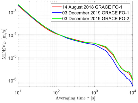
Figure 13.
MDEV of the radial orbital errors of GRACE FO-1 and GRACE FO-2 on different test days without applying any clock models.
For GRACE FO-1 on 3 December 2019, the reduced mis-modeled effects lead to smaller improvements in the radial orbits. Figure 14 illustrates the improvement areas for the radial orbits, applying the same clock models as in Figure 12. Although the red areas with large improvements around or above 15% disappear, the general patterns remain similar to those in Figure 12. A smoothing window of 300 s to 500 s appears to be a good solution when applying the PWL model with a PWL length from 300 s to 1200 s, or using the 2.5-state model with from to .
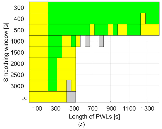
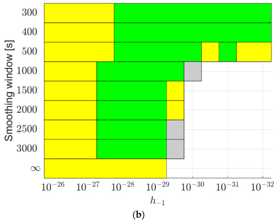
Figure 14.
Improvements in the radial orbits when applying (a) the PWL model and (b) the 2.5-state model to the USO in GRACE FO-1 on 3 December 2019 using the CNES real-time products. The grey areas denote improvement between 0% and 5%, the yellow areas between 5% and 10%, and the green areas between 10% and 15%.
The conclusions above do not change when testing on another satellite, GRACE FO-2, on 3 December 2019 (see Figure 15). With the improvements increased to above 15% in this case, a smoothing window of 300 s to 500 s still appears to be a proper solution when applying the PWL model with a PWL length from 300 s to 1200 s, or using the 2.5-state model with from to .
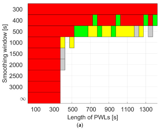
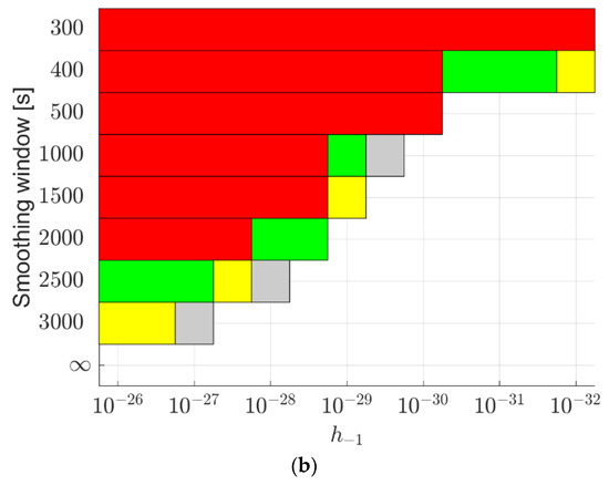
Figure 15.
Improvements in the radial orbits when applying (a) the PWL model and (b) the 2.5-state model to the USO in GRACE FO-2 on 3 December 2019 using the CNES real-time products. The grey areas denote improvement between 0% and 5%, the yellow areas between 5% and 10%, the green areas between 10% and 15%, and red areas around or above 15%.
It should be noted that the conclusions apply only to LEO satellites equipped with USOs. Moreover, for LEO satellite clocks containing dramatically different external systematic effects, it is suggested to use the proposed strategy to first search for appropriate model values before applying the clock models.
In this study, clock modeling is performed for the GPS-only scenario due to the limited signals tracked on board the tested LEO satellites. When multi-GNSS signals are received by the LEO satellites, a better measurement geometry can be provided, which enables higher precision of the radial orbits and lower sensitivity of the orbits to the correlations between the orbital and clock parameters. In such case, the improvements in the radial orbits induced by clock modeling could be smaller. In contrast, for small satellites such as CubeSats with less stable and continuous data tracking, the improvements in the radial orbits could be greater when modeling clocks of the same type.
5. Conclusions
This contribution studies the benefits of LEO clock modeling in the kinematic LEO POD. Real data from LEO satellites equipped with USOs were tested for clock modeling in the kinematic POD process. This study aims not only to reduce the short-term noise in the kinematic orbits, but also the mis-modeled effects induced by, e.g., real-time GNSS orbital and clock errors, which are often enlarged in the kinematic POD mode due to the strong correlation between the orbits and the clocks in the estimation process.
To benefit from the good clock stability in current and future LEO satellites, the mid- to long-term systematic effects caused by relativistic effects and the external environment are suggested to be a priori corrected in the O-C terms. In this study, these trends are captured by the epoch-wise clock estimates, and are obtained by smoothing using different windows. Too-strong smoothing would limit the orbital improvement, and too-weak smoothing would hamper the clock modeling and easily lead to degradations in the orbit estimation. A balance is thus investigated in this contribution.
Two different clock models were applied in the POD processing, i.e., the PWL model with different time lengths and the 2.5-state model with different values for different noise types. Using real data from GRACE FO-1 and the CNES real-time GPS products, it was found that detrending with a smoothing window of 300 to 500 s and applying the PWL model with lengths from 300 to 1200 s, or using the 2.5-state model with (for FFN) from to , one could expect improvements larger than 10% in the radial orbits.
Author Contributions
K.W. designed the research, processed the data and wrote the paper; A.E.-M. and X.Y. revised the paper. All authors have read and agreed to the published version of the manuscript.
Funding
This research is funded by the National Time Service Center, Chinese Academy of Sciences (CAS) (No. E167SC14), the National Natural Science Foundation of China (No. 12073034), the CAS “Light of West China” Program (XAB2021YN25), the Shaanxi Province Key R&D Program Project (2022KW-29), and the Australian Research Council—discovery project (No. DP 190102444).
Data Availability Statement
The CNES real-time products are available at http://www.ppp-wizard.net/products/REAL_TIME/, accessed on 14 June 2023. The CODE final products are available at http://ftp.aiub.unibe.ch/CODE/, accessed on 14 June 2023. The data of GRACE Follow-On satellites are available at https://podaac-tools.jpl.nasa.gov/drive/files/allData/gracefo/L1B/JPL/RL04/ASCII/, accessed on 14 June 2023.
Acknowledgments
We would like to acknowledge the support of the international GNSS monitoring and assessment system (iGMAS) at the National Time Service Center and the National Space Science Data Center, National Science & Technology Infrastructure of China (http://www.nssdc.ac.cn, accessed on 14 June 2023).
Conflicts of Interest
The authors declare no conflict of interest.
References
- Reid, T.G.; Neish, A.M.; Walter, T.; Enge, P.K. Broadband LEO constellations for navigation. Navig. J. Inst. Navig. 2018, 65, 205–220. [Google Scholar] [CrossRef]
- Michalak, G.; Glaser, S.; Neumayer, K.; König, R. Precise orbit and Earth parameter determination supported by LEO satellites, inter-satellite links and synchronized clocks of a future GNSS. Adv. Space Res. 2021, 68, 4753–4782. [Google Scholar] [CrossRef]
- Lawrence, D.; Cobb, H.S.; Gutt, G.; O’Connor, M.; Reid, T.G.; Walter, T. Navigation from LEO. 2017. Available online: https://www.gpsworld.com/innovation-navigation-from-leo/ (accessed on 14 June 2023).
- Li, K.; Zhou, X.; Wang, W.; Gao, Y.; Zhao, G.; Tao, E.; Xu, K. Centimeter-level orbit determination for TG02 spacelab using onboard GNSS data. Sensors 2018, 18, 2671. [Google Scholar] [CrossRef]
- Faragher, R.; Ziebart, M. OneWeb LEO PNT: Progress or Risky Gamble. Inside GNSS 2020, 28. Available online: https://insidegnss.com/oneweb-leo-pnt-progress-or-risky-gamble/ (accessed on 14 June 2023).
- Krawinkel, T.; Schön, S. Benefits of receiver clock modeling in code-based GNSS navigation. GPS Solut. 2016, 20, 687–701. [Google Scholar] [CrossRef]
- Yang, Y.; Yue, X.; Yuan, J.; Rizos, C. Enhancing the kinematic precise orbit determination of low earth orbiters using GPS receiver clock modelling. Adv. Space Res. 2014, 54, 1901–1912. [Google Scholar] [CrossRef]
- Montenbruck, O.; Gill, E.; Lutze, F. Satellite orbits: Models, methods, and applications. Appl. Mech. Rev. 2002, 55, B27–B28. Available online: https://link.springer.com/book/10.1007/978-3-642-58351-3 (accessed on 14 June 2023). [CrossRef]
- Guo, N.-N.; Zhou, X.-H.; Li, K.; Wu, B. Research on the impact factors of GRACE precise orbit determination by dynamic method. J. Appl. Geod. 2018, 12, 249–257. [Google Scholar] [CrossRef]
- Mao, X.; Arnold, D.; Girardin, V.; Villiger, A.; Jäggi, A. Dynamic GPS-based LEO orbit determination with 1 cm precision using the Bernese GNSS Software. Adv. Space Res. 2021, 67, 788–805. [Google Scholar] [CrossRef]
- Case, K.; Kruizinga, G.; Wu, S. GRACE Level 1B Data Product User Handbook; Jpl D-22027; 2010; Available online: https://earth.esa.int/eogateway/documents/20142/37627/GRACE-L1B-Handbook-v1.3.pdf (accessed on 14 June 2023).
- Kornfeld, R.P.; Arnold, B.W.; Gross, M.A.; Dahya, N.T.; Klipstein, W.M.; Gath, P.F.; Bettadpur, S. GRACE-FO: The gravity recovery and climate experiment follow-on mission. J. Spacecr. Rocket. 2019, 56, 931–951. [Google Scholar] [CrossRef]
- Fletcher, K. Sentinel-3: ESA’s Global Land and Ocean Mission for GMES Operational Services; ESA Communications, 2012; Available online: https://sentinel.esa.int/documents/247904/351187/S3_SP-1322_3.pdf (accessed on 14 June 2023).
- Zhou, X.; Jiang, W.; Chen, H.; Li, Z.; Liu, X. Improving the GRACE kinematic precise orbit determination through modified clock estimating. Sensors 2019, 19, 4347. [Google Scholar] [CrossRef] [PubMed]
- Weinbach, U.; Schön, S. Improved GRACE kinematic orbit determination using GPS receiver clock modeling. GPS Solut. 2013, 17, 511–520. [Google Scholar] [CrossRef]
- Allahvirdi-Zadeh, A.; Wang, K.; El-Mowafy, A. POD of small LEO satellites based on precise real-time MADOCA and SBAS-aided PPP corrections. GPS Solut. 2021, 25, 31. [Google Scholar] [CrossRef]
- Larson, K.M.; Ashby, N.; Hackman, C.; Bertiger, W. An assessment of relativistic effects for low Earth orbiters: The GRACE satellites. Metrologia 2007, 44, 484. Available online: https://iopscience.iop.org/article/10.1088/0026-1394/44/6/007 (accessed on 14 June 2023). [CrossRef]
- Wang, K.; El-Mowafy, A. LEO satellite clock analysis and prediction for positioning applications. Geo Spat. Inf. Sci. 2022, 25, 14–33. [Google Scholar] [CrossRef]
- Montenbruck, O.; Hackel, S.; Wermuth, M.; Zangerl, F. Sentinel-6A precise orbit determination using a combined GPS/Galileo receiver. J. Geod. 2021, 95, 109. [Google Scholar] [CrossRef]
- Ge, H.; Wu, T.; Li, B. Characteristics analysis and prediction of Low Earth Orbit (LEO) satellite clock corrections by using least-squares harmonic estimation. GPS Solut. 2022, 27, 38. [Google Scholar] [CrossRef]
- Wen, H.Y.; Kruizinga, G.; Paik, M.; Landerer, F.; Bertiger, W.; Sakumura, C.; Bandikova, T.; Mccullough, C. Gravity Recovery and Climate Experiment Follow-on (GRACE-FO) Level-1 Data Product User Handbook. JPL D-56935 (URS270772); 2019. Available online: https://podaac-tools.jpl.nasa.gov/drive/files/allData/gracefo/docs/GRACE-FO_L1_Handbook.pdf (accessed on 14 June 2023).
- Dach, R.; Schaer, S.; Meindl, M.; Bock, H.; Jäggi, A.; Lutz, S.; Meyer, U.; Ostini, L.; Prange, L.; Steinbach, A. Global Multi-GNSS Processing at CODE. J. Geod. 2009, 83, 353–365. [Google Scholar] [CrossRef]
- Ye, Z.; Li, H.; Wang, S. Characteristics analysis of the GNSS satellite clock. Adv. Space Res. 2021, 68, 3314–3326. [Google Scholar] [CrossRef]
- Kudrys, J.; Prochniewicz, D.; Zhang, F.; Jakubiak, M.; Maciuk, K. Identification of BDS Satellite Clock Periodic Signals Based on Lomb-Scargle Power Spectrum and Continuous Wavelet Transform. Energies 2021, 14, 7155. [Google Scholar] [CrossRef]
- GMV. Sentinels POD Product Handbook. Copernicus Sentinel-1, -2 and -3 Precise Orbit Determination Service (SENTINELSPOD). 2020. Available online: https://sentinel.esa.int/documents/247904/3372484/Sentinels-POD-Product-Handbook.pdf (accessed on 14 June 2023).
- Li, X.; Zhang, K.; Meng, X.; Zhang, Q.; Zhang, W.; Li, X.; Yuan, Y. LEO–BDS–GPS integrated precise orbit modeling using FengYun-3D, FengYun-3C onboard and ground observations. GPS Solut. 2020, 24, 48. [Google Scholar] [CrossRef]
- Wang, L.; Xu, B.; Fu, W.; Chen, R.; Li, T.; Han, Y.; Zhou, H. Centimeter-level precise orbit determination for the Luojia-1A satellite using BeiDou observations. Remote Sens. 2020, 12, 2063. [Google Scholar] [CrossRef]
- Yang, H.; Yang, X.; Zhang, Z.; Sun, B.; Qin, W. Evaluation of the Effect of High-order Ionopsheric Delay on GPS Precise Point Positioning Time Transfer. Remote Sens. 2020, 12, 2129. [Google Scholar] [CrossRef]
- Wang, K.; El-Mowafy, A.; Rizos, C. Integrity monitoring for precise orbit determination of LEO satellites. GPS Solut. 2021, 26, 32. [Google Scholar] [CrossRef]
- Dach, R.; Lutz, S.; Walser, P.; Fridez, P. Bernese GNSS Software Version 5.2; University of Bern, Bern Open Publishing: Bern, Switzerland, 2015. [Google Scholar] [CrossRef]
- Li, X.; Ma, F.; Li, X.; Lv, H.; Bian, L.; Jiang, Z.; Zhang, X. LEO constellation-augmented multi-GNSS for rapid PPP convergence. J. Geod. 2019, 93, 749–764. [Google Scholar] [CrossRef]
- Pavlis, N.; Holmes, S.; Kenyon, S.; Factor, J. An Earth Gravitational Model to Degree 2160: EGM2008. In Proceedings of the European Geosciences Union General Assembly, Vienna, Austria, 13–18 April 2008; Available online: http://earth-info.nga.mil/GandG/wgs84/gravitymod/egm2008/index.html (accessed on 14 June 2023).
- Standish, E. JPL Planetary and Lunar Ephemerides, DE405/LE405 (Memo IOM 312. F-98-048; Pasadena: JPL). 1998. Available online: http://ssd.jpl.nasa.gov/iau-comm4/de405iom/de405iom.pdf (accessed on 14 June 2023).
- Petit, G.; Luzum, B. IERS conventions. IERS Tech. Note 2010, 36, 2010. [Google Scholar]
- Lyard, F.; Lefevre, F.; Letellier, T.; Francis, O. Modelling the global ocean tides: Modern insights from FES2004. Ocean. Dyn. 2006, 56, 394–415. [Google Scholar] [CrossRef]
- Wang, K.; Rothacher, M. Stochastic modeling of high-stability ground clocks in GPS analysis. J. Geod. 2013, 87, 427–437. [Google Scholar] [CrossRef]
- Wang, K. Advanced Modeling and Algorithms for High-Precision GNSS Analysis; ETH: Zurich, Switzerland, 2016. [Google Scholar] [CrossRef]
- Van Dierendonck, A.J.; McGraw, J. Relationship between Allan variances and Kalman filter parameters. In Proceedings of the 16th Annual Precise Time and Time Interval Systems and Applications Meeting, Greenbelt, MD, USA, 27–29 November 1984; pp. 273–293. [Google Scholar]
- Humpherys, J.; West, J. Kalman filtering with Newton’s method [lecture notes]. IEEE Control Syst. Mag. 2010, 30, 101–106. [Google Scholar] [CrossRef]
- Odijk, D.; Zhang, B.; Khodabandeh, A.; Odolinski, R.; Teunissen, P.J. On the estimability of parameters in undifferenced, uncombined GNSS network and PPP-RTK user models by means of S-system theory. J. Geod. 2016, 90, 15–44. [Google Scholar] [CrossRef]
- Allan, D.W. Time and Frequency (Time-Domain) Characterization, Estimation, and Prediction of Precision Clocks and Oscillators. IEEE Trans. Ultrason. Ferroelectr. Freq. Control 1987, 34, 647–654. [Google Scholar] [CrossRef] [PubMed]
- Kazmierski, K.; Sośnica, K.; Hadas, T. Quality assessment of multi-GNSS orbits and clocks for real-time precise point positioning. GPS Solut. 2018, 22, 11. [Google Scholar] [CrossRef]
- Riley, W.J.; Howe, D.A. Handbook of Frequency Stability Analysis; National Institute of Standards and Technology: Gaithersburg, MD, USA, 2008.
- Wu, M.; Sun, B.; Wang, Y.; Zhang, Z.; Su, H.; Yang, X. Sub-nanosecond one-way real-time time service system based on UTC. GPS Solut. 2021, 25, 44. [Google Scholar] [CrossRef]
Disclaimer/Publisher’s Note: The statements, opinions and data contained in all publications are solely those of the individual author(s) and contributor(s) and not of MDPI and/or the editor(s). MDPI and/or the editor(s) disclaim responsibility for any injury to people or property resulting from any ideas, methods, instructions or products referred to in the content. |
© 2023 by the authors. Licensee MDPI, Basel, Switzerland. This article is an open access article distributed under the terms and conditions of the Creative Commons Attribution (CC BY) license (https://creativecommons.org/licenses/by/4.0/).