Article

Kalman Filter, ANN-MLP, LSTM and ACO Methods Showing Anomalous GPS-TEC Variations Concerning Turkey’s Powerful Earthquake (6 February 2023)

by
Mehdi Akhoondzadeh
Photogrammetry and Remote Sensing Department, School of Surveying and Geospatial Engineering, College of Engineering, University of Tehran, North Amirabad Ave., Tehran 1417614411, Iran
Remote Sens. 2023, 15(12), 3061; https://doi.org/10.3390/rs15123061
Submission received: 9 May 2023 / Revised: 9 June 2023 / Accepted: 10 June 2023 / Published: 11 June 2023
(This article belongs to the Special Issue Remote Sensing Data Application for Early Warning System)

Abstract

:
On 6 February 2023, at 1:17:34 UTC, a powerful Mw = 7.8 earthquake shook parts of Turkey and Syria. Investigating the behavior of different earthquake precursors around the time and location of this earthquake can facilitate the creation of an earthquake early warning system in the future. Total electron content (TEC) obtained from the measurements of GPS satellites is one of the ionospheric precursors, which in many cases has shown prominent anomalies before the occurrence of strong earthquakes. In this study, five classical and intelligent anomaly detection algorithms, including median, Kalman filter, artificial neural network (ANN)-multilayer perceptron (MLP), long short-term memory (LSTM), and ant colony optimization (ACO), have been used to detect seismo-anomalies in the time series of TEC changes in a period of about 4 months, from 1 November 2022 to 17 February 2023. All these algorithms show outstanding anomalies in the period of 10 days before the earthquake. The median method shows clear TEC anomalies in 1, 2 and, 3 days before the event. Since the behavior of the time series of a TEC parameter is complex and nonlinear, by implementing the Kalman filter method, pre-seismic anomalies were observed in 1, 2, 3, 5, and 10 days prior to the main shock. ANN as an intelligent-method-based machine learning also emphasizes the abnormal behavior of the TEC parameter in 1, 2, 3, 6, and 10 days before the earthquake. As a deep-learning-based predictor, LSTM indicates that the TEC value in the 10 days prior to the event has crossed the defined permissible limits. As an optimization algorithm, the ACO method shows behavior similar to Kalman filter and MLP algorithms by detecting anomalies 3, 7, and 10 days before the earthquake. In a previous paper, the author showed the findings of implementing a fuzzy inference system (FIS), indicating that the magnitude of the mentioned powerful earthquake could be predicted during about 9 to 1 day prior to the event. The results of this study also confirm the findings of another study. Therefore, considering that different lithosphere–atmosphere–ionosphere (LAI) precursors and different predictors show abnormal behavior in the time period before the occurrence of large earthquakes, the necessity of creating an earthquake early warning system based on intelligent monitoring of different precursors in earthquake-prone areas is emphasized.

1. Introduction

Due to the heavy damage caused by powerful earthquakes, many efforts have been made to predict them [1,2,3]. Since earthquakes occur following the occurrence of complex and nonlinear behaviors in different physical and chemical parameters in different layers of the earth, including the lithosphere, atmosphere, and ionosphere, several studies have been carried out based on monitoring the behavior of earthquake precursors around the time and location of powerful earthquakes. However, due to the fact that the occurrence of these anomalies can have non seismic causes as well, so far, it has not been possible to accurately predict the location, time, and magnitude of earthquakes before the occurrence with low uncertainty. With the launch of different remote sensing satellites and the collection of various image and non-image data with a short temporal resolution, low cost, and wide coverage, the speed and quality of articles related to earthquake precursors have significantly improved [4,5,6,7]. Since, by relying on the behavior of a single precursor, it is not reasonable to make decisions about pre-seismic anomalies with low uncertainty, it is possible to detect seismically prone anomalies with low uncertainty by using different precursors in different layers of the earth and implementing the data fusion. In addition to the integration of different precursors, it is possible to reduce the uncertainty in the detection of pre-seismic anomalies by combining the results of different anomaly detection algorithms and predictors [8,9,10,11,12,13]. Essam et al. (2022) suggested artificial neural network models as a tool for predicting ground motion parameters, namely, earthquake acceleration, depth, and velocity, in Terengganu. They presented a comparison of the results of ANN with the results of random forest (RF) [14]. Portillo and Moya (2023) proposed a novel semi-supervised classification approach for identifying urban changes induced by the 2023 Turkey earthquake between images recorded at different times. The method was applied to the interferometric coherence computed from C-band synthetic aperture radar images from Sentinel-1 [15]. Marhain et al. (2021) implemented a few artificial intelligence algorithms, such as support vector machine, boosted decision tree regression, random forest, and multivariate adaptive regression spline, to develop the best model algorithm in earthquake prediction. In their study, meteorological data were collected from several stations in Terengganu and processed for normalization, and the data were analyzed using algorithms, and the performance was evaluated [16]. Li et al. (2023) processed Sentinel-1 and GPS data to derive the complete surface displacement caused by the 2023 Turkey earthquake sequence [17]. Murti et al. (2022) proposed an earthquake multiclassification detection with machine learning algorithms that can distinguish earthquake and non earthquake and vandalism vibration using acceleration seismic waves [18]. In this study, by using five common and competent classical and intelligent algorithms, and combining their results, potentially pre-seismic anomalies related to the powerful earthquake in Turkey (6 February 2023) are discussed.

Case Study

A strong earthquake of Mw = 7.8 magnitude happened on 6 February 2023 at 1:17:34 UT (LT = UT + 3:00) at the geographic location of 37.22°N and 37.02°E and a 10.00 km depth (https://earthquake.usgs.gov/earthquakes/, accessed on 01 May 2023). The mentioned earthquake was a result of the strike-slip transcurrence of three plates, including African, Anatolian, and Arabian, among a vertical fault plane. Figure 1 indicates the geographic location of the registered earthquakes with an M ≥ 4.1 magnitude around the epicenter from 6 to 17 February 2023. The plate boundaries are shown as red dashed lines and the two foreshocks as black diamonds.

2. Data

2.1. TEC Data

Total electron content (TEC) data have played an important role in detecting seismic ionospheric anomalies [6,21,22,23,24].
With the expansion of positioning networks based on GPS receivers, access to ionosphere data has been provided. TEC is the number of electrons in a block between the satellite and the ground station or between the two satellites [25,26,27]. GPS signals received by ground stations have several effects, including ionosphere and troposphere. The ionosphere, unlike the troposphere, is a dispersive medium, and since GPS satellites send two signal frequencies, including f1 = 1575.42 MHz and f2 = 1227.60 MHz, by measuring the modulation on the carrier phases recorded by dual-frequency receivers, the ionosphere effects can be assessed.
Using about 150 GPS sites of the International GNSS Service (IGS) and other institutions receivers, the NASA Jet Propulsion Laboratory (JPL) has provided a product called Global Ionospheric Map (GIM). TEC variations can be analyzed using these maps, which are constructed with a time resolution of 2 h as 5° × 2.5° (longitude, latitude) grid.

2.2. Solar–Geomagnetic Data

Ionospheric parameters are influenced by the geophysical conditions of the sun and geomagnetic storms, especially in the polar and equatorial regions. Significant geomagnetic field disturbances are observed during the periods of solar–terrestrial interactions and perturbations. Therefore, it is possible that in the absence of seismic activities, due to solar and geomagnetic conditions, perturbations in ionospheric parameters can be observed. Therefore, to distinguish the potentially pre-seismo-ionospheric anomalies from solar geomagnetic disturbances, the solar-geomagnetic indices including F10.7, Kp, ap, and Dst should be controlled [28]. It should be noted that the ionospheric effect of solar–geomagnetic storms is global, which is observed all over the world, but the seismo-ionospheric effect is local and observed only around the epicenter with distance less than the Dobrovolsky area [29,30]. Each index is more representative of some characteristics of the status of the geomagnetic field; in particular, ap and Kp are global indices measured from several geomagnetic observatories at different latitudes in linear and logarithm scales. The Dst index is measured by four geomagnetic observatories around the dip equator, and in the impact of a geomagnetic storm, its values become negative and could reach some hundreds of nT of intensity in the function of the strength of the same perturbation. The F10.7 index represents a measure of diffuse, nonradiative heating of the coronal plasma trapped by magnetic fields over active regions, and is an excellent indicator of overall solar activity levels [31].

3. Methods

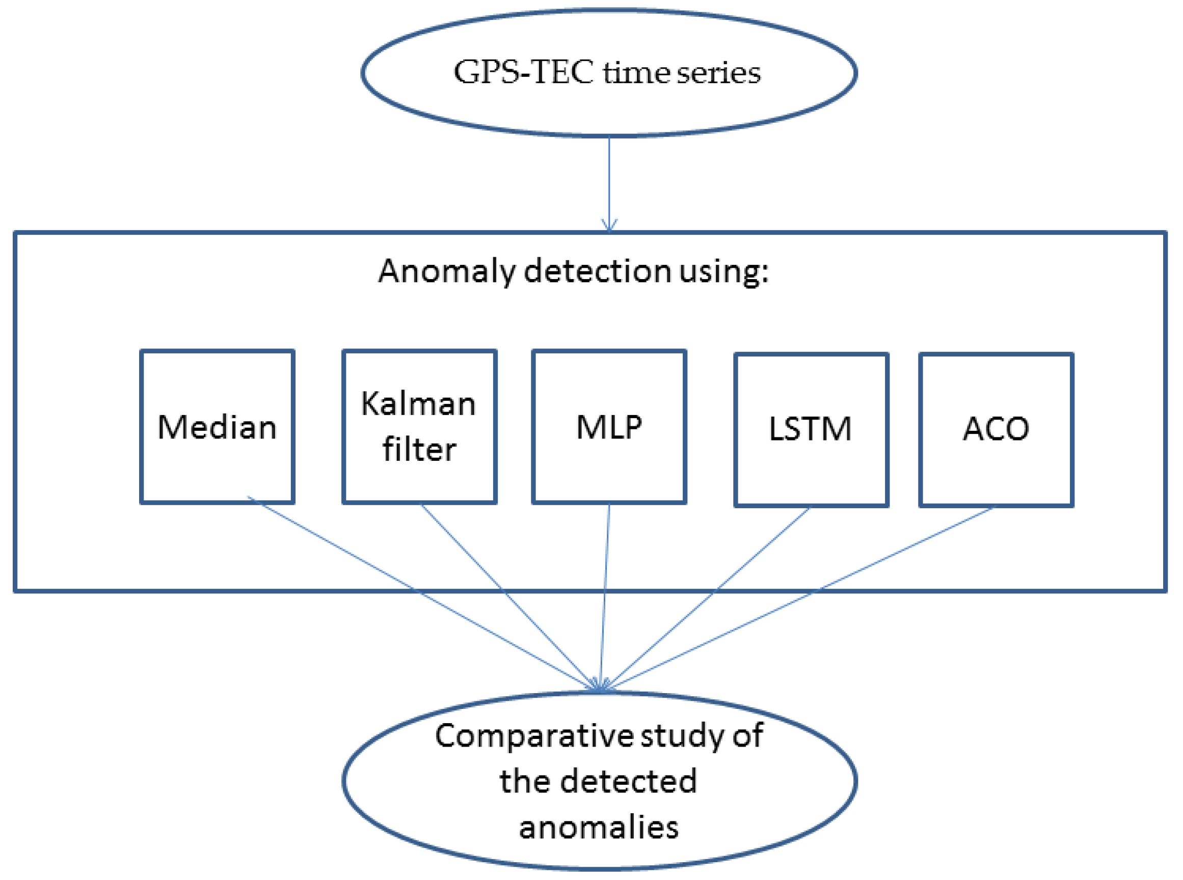
Since the behavior of the time series of ionospheric precursors is strictly nonlinear and complex, the use of machine learning and pattern recognition intelligent methods seems necessary in order to detect unusual patterns. In this study, in addition to the median method, four other algorithms, including Kalman filter, multilayer perceptron (MLP), long short-term memory (LSTM), and ant colony optimization (ACO), have also been implemented to detect pre-seismic anomalies. Figure 2 shows a flowchart of anomaly detection steps with the mentioned methods.

3.1. Median

Since the daily variations of the ionosphere do not follow a Gaussian distribution function, the median and the interquartile range of data are suggested to determine upper and lower limits (Equations (1)–(3)) and distinguish potentially seismic anomalies from the other natural and unknown variations.
x h i g h = m + k × i q r
x l o w = m k × i q r
D x = x m i q r
Here, m, iqr, x, x h i g h , and x l o w are median, interquartile range, TEC value, upper limit, and lower limit, respectively. The parameter k can decrease or increase the allowed range of TEC parameter change. Dx shows the deviation of the desired parameter (TEC) from the defined permissible limits. If Dx exceeds the defined permissible value, the parameter value is interpreted as abnormal. If an observed TEC falls out of either the associated lower or higher bound (|DTEC| > 1), we conclude with a confidence level of about 80–85% that a lower or higher abnormal signal is detected [22]. The value of k depends on the magnitude of the earthquake and also the nonlinearity of the parameter changes. It should be noted that these two parameters, m and iqr values, are calculated for the entire time period (1 November 2022 to 17 February 2023), but for any interval of 2 h, which is the time resolution of TEC values.

3.2. Kalman Filter

The Kalman filter can be applied for prediction, filtering, and smoothing [21]. This filter includes two equations of state and measurement to optimize forecasting equations by the minimization of error covariance and estimating the state variables. This filter can be applied for both linear and nonlinear systems and also stationary and dynamic analyses. In this algorithm, first, a prediction is made, and then the prediction is corrected based on the observations, and the prediction is made again. In cases where the equations of state and measurement are nonlinear, the equations can be linearized using the Taylor series expansion. In this case, this method is called extended Kalman filter, and it is very widely used for forecasting in nonlinear time series, such as TEC ionospheric variation [14]. If the difference between the estimated and observed values of TEC exceeds the predefined limits (i.e., m ± k × i q r ; m, iqr, and k indicate the median, interquartile range, and coefficient parameters, respectively), the observed TEC parameter in a quiet geomagnetic condition (i.e., F10.7 < 180 SFU, |Dst| ≤ 20 nT, ap < 20 nT, and Kp < 3 nT (solar flux unit)) could be considered an anomalous value. More details of this method are described in [21].

3.3. ANN-MLP

Artificial neural networks are among the intelligent systems that are able to provide a model for solving nonlinear problems by creating a relationship between input and output parameters in various supervised and unsupervised conditions. Although this model is in the form of a black box, it is possible to obtain an optimal model by tuning different values of the number of hidden layers and neurons and evaluating the accuracy of the results. ANN can also be used in time series forecasting. This is done by building the state matrix from the patterns in the data training section. The most common and successful category of neural network is the feed forward multilayer perceptron (MLP). Since the author has implemented this method in other case studies, more details of this method are described in [23].

3.4. LSTM

Due to a lack of vanishing gradient in the recurrent neural network, Hochreiter and Schmidhuber (1997) developed the long short-term memory (LSTM) algorithm [31]. This method infers the time dynamic behaviour of time series during running time using the shared parameters. Similar to RNN, LSTM includes three layers, but in order to control the pass of information to the memory cells, a hidden layer of LSTM consists of three units, which are input, forget, and output. More details of this method for time series forecasting are described in [31]. LSTM, such as ANN, is trained and estimates the values in time period of the test data, and if the error values obtained via the differences between estimated and observed values are beyond the predefined limits m ± i q r (where m and iqr are the median and interquartile range, respectively), the anomalous day is hinted.

3.5. ACO

Since animals in nature usually choose the best among different solutions to achieve the goal, by modelling their behaviors, mathematical algorithms can be provided to solve optimization problems. One of these algorithms is ant colony optimization (ACO), which was presented by Dorigo in 1992 [32], based on the natural behaviour of a colony of ants to find the best path to reach food. This algorithm is based on the idea that ants leave a trail on the way between the nest and the food by secreting a substance called pheromone, which causes other ants to follow the pheromone traces to take a shorter path to the food. The pheromone evaporates and allows other ants to randomly search for other solutions. Therefore, this algorithm is based on two parameters, pheromone and distance. Some researchers have suggested the use of this algorithm in the process of forecasting in time series, the details of which are given, for example, in the article [33].

4. Results

Figure 3a–c represent the geomagnetic indices of Kp, ap, and Dst, respectively, in the time period of 1 November 2022 to 17 February 2023. The values of geomagnetic indices are displayed in quiet conditions with green color and in nonquiet geomagnetic conditions with red color. A black star indicates the earthquake origin time. The horizontal axis shows the days relative to the day of the earthquake. The y-axis represents the universal time. In the period before the day of the earthquake, these indices show relatively quiet geomagnetic activities. However, on the day of the earthquake, the Kp index shows a relatively high value. Figure 3d indicates the time series of solar radio flux (F10.7) in the time period of 1 November 2022 to 17 February 2023. It can be seen that the earthquake happened after a high increase in this solar index about 19 to 26 days before the earthquake. In some previous studies, the possible connection between solar activities and large earthquakes has been discussed, although this hypothesis has not been proven yet [28]. In this study, potentially pre-seismic TEC anomalies are discussed during the quiet solar–geomagnetic conditions (i.e., F10.7 < 180 SFU, |Dst| ≤ 20 nT, ap < 20 nT, and Kp < 3 nT).
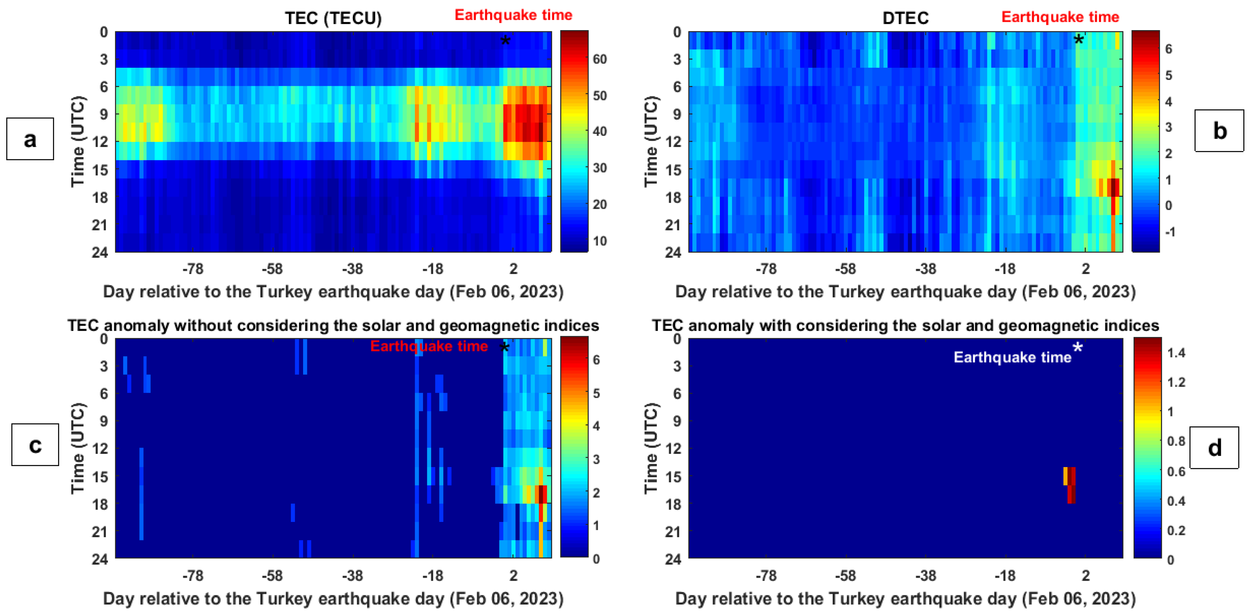
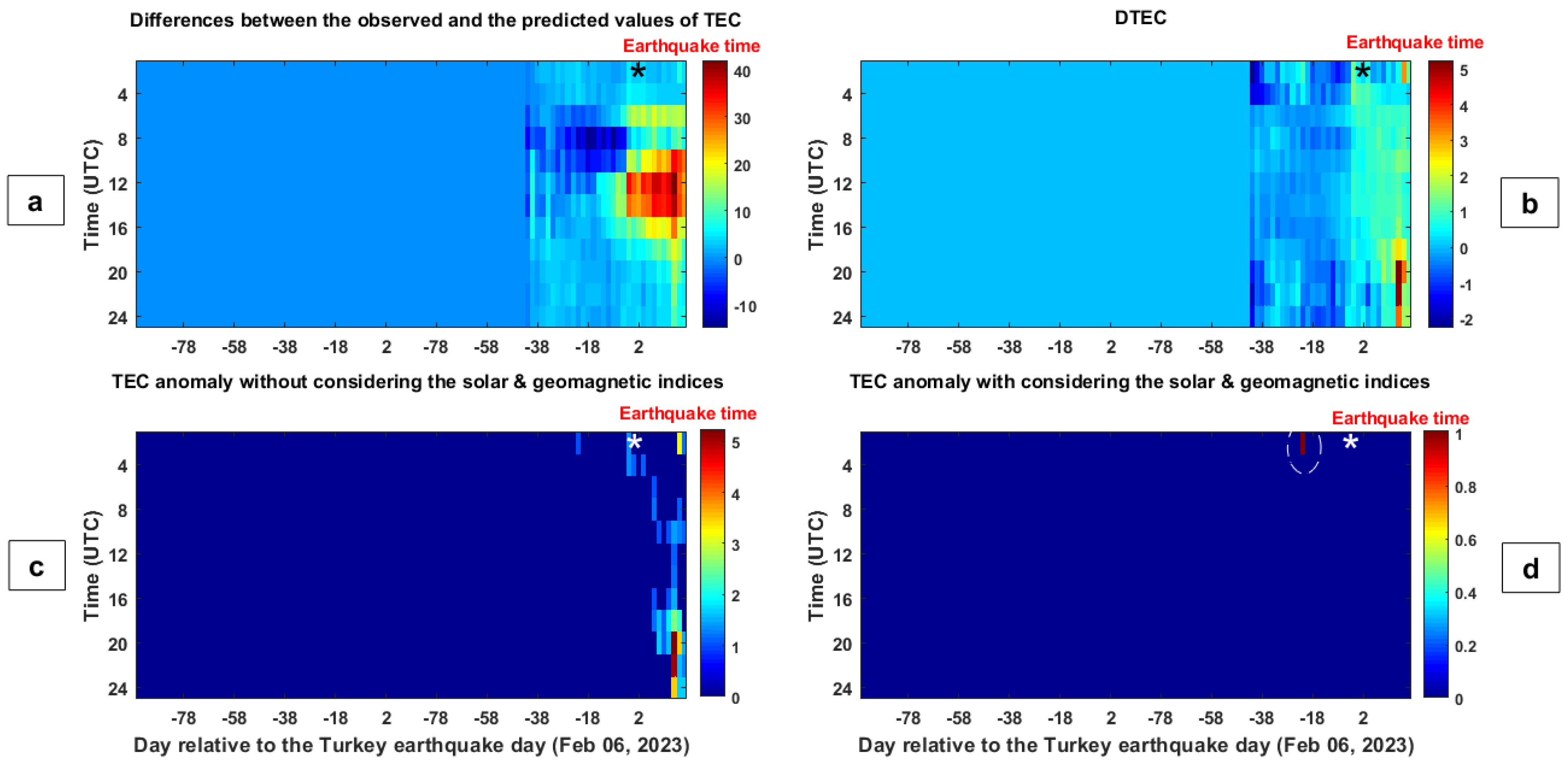
Figure 4a represents GIM-TEC variations during the period of 1 November 2022 to 17 February 2023. It is difficult to detect preseismic anomalies in quiet geomagnetic conditions from this figure. After implementing the median anomaly detection method and defining the upper and lower permissible limits, the amount of deviation of the TEC parameter from the defined limits (DTEC) is calculated according to Equation (3). It should be noted that the median method is applying every 2 h (12 times) according to the time resolution of TEC data during the studied time period (109 days). Figure 4b shows variations of DTEC in the time period of 1 November 2022 to 17 February 2023. In Figure 4c, observed TEC anomalies after implementing the median method are shown when D T E C > 1 . As mentioned before, the TEC anomalies (DTEC) in Figure 4c are considered to be potentially seismic anomalies when F10.7 < 180 SFU, |Dst| ≤ 20 nT, ap < 20 nT, and Kp < 3 nT. The final TEC anomalies are shown in Figure 4d. The striking anomalies are sharply seen from 1 to 3 days prior to the event. The TEC anomaly asses a value of 4.1%, 3 days before the earthquake at 16:00 UTC. Additionally, the TEC values exceed the upper limit (m + iqr), 1 day preceding the main shock at 16:00 and 18:00 UTC with unusual values of 39.8% and 48.6% from the upper limit. Details of other anomalies observed by this method are shown in Table 1.
After applying the Kalman filter, the error values obtained via the differences between the estimated and observed TEC values during the period of 1 November 2022 to 17 February 2023 are shown in Figure 5a. It should be noted that 60% of the data are considered for the training stage and determining the optimal parameters. In the next step, the permissible limits of change for this difference are determined by calculating the median and the interquartile range for every 2 h and during the period of days under study, and the amount of deviation from the permissible limits is calculated using Equation (3). Figure 5b shows the obtained DTEC values. In the next step, in Figure 5c, DTEC values are shown in conditions where the absolute value is greater than 1 ( D T E C > 1 ). Finally, seismic TEC anomalies in quiet solar–geomagnetic conditions are shown in Figure 5d.
The results of implementing the Kalman filter method show that the TEC values in 1, 2, 3, 5, and 10 days before the earthquake have crossed the defined limits. The highest deviation of TEC from the upper limit of 58.7% is observed 1 day before the main shock at 06:00 UTC. Details of other observed anomalies are given in Table 1.
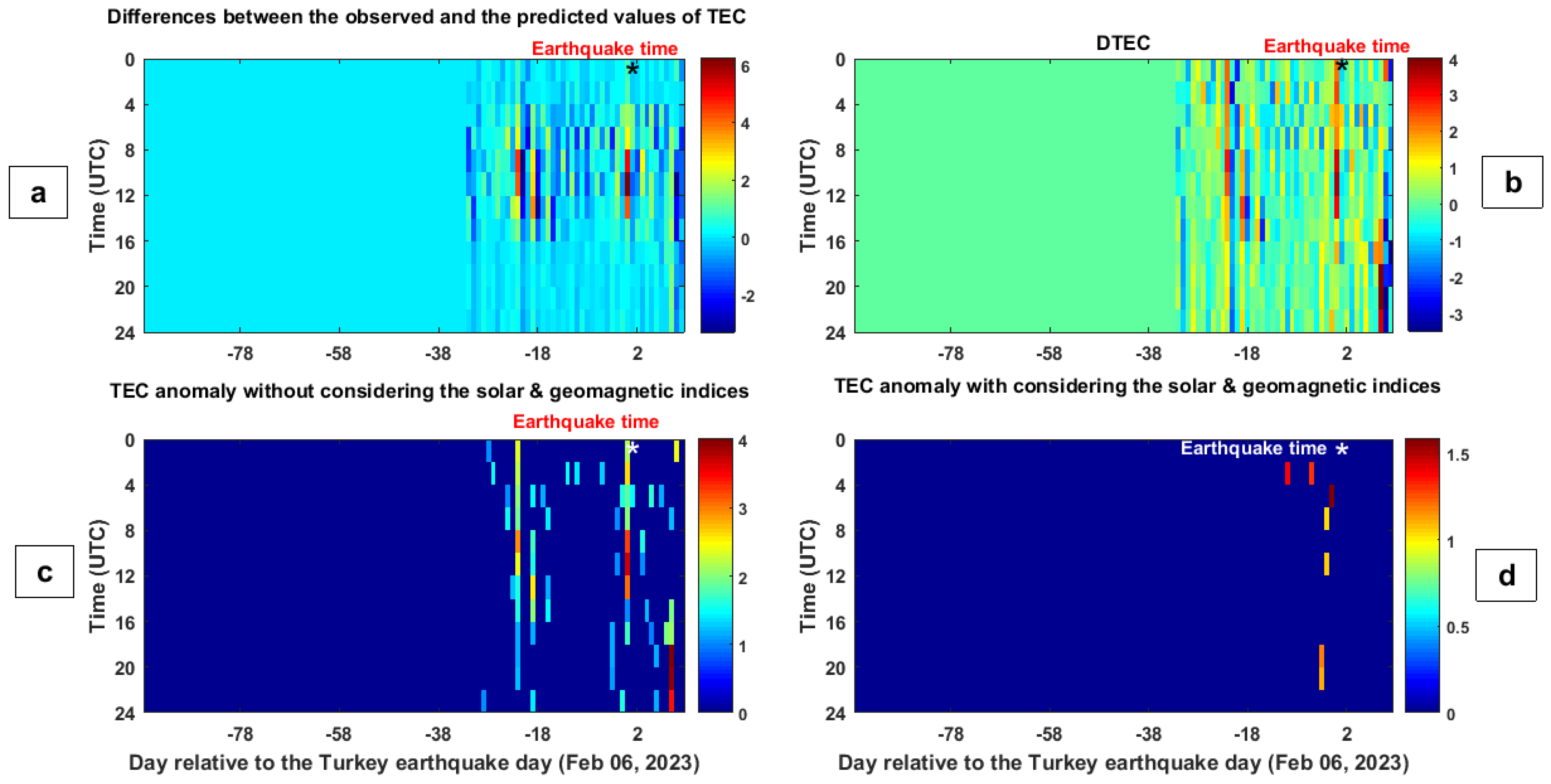
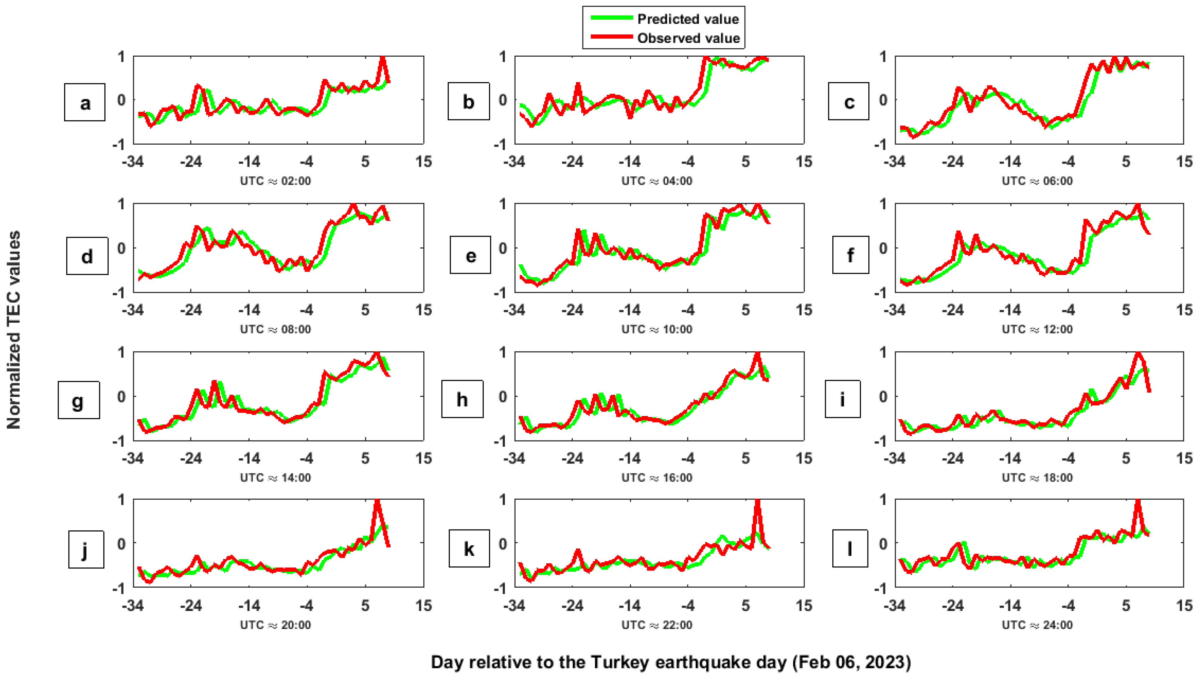
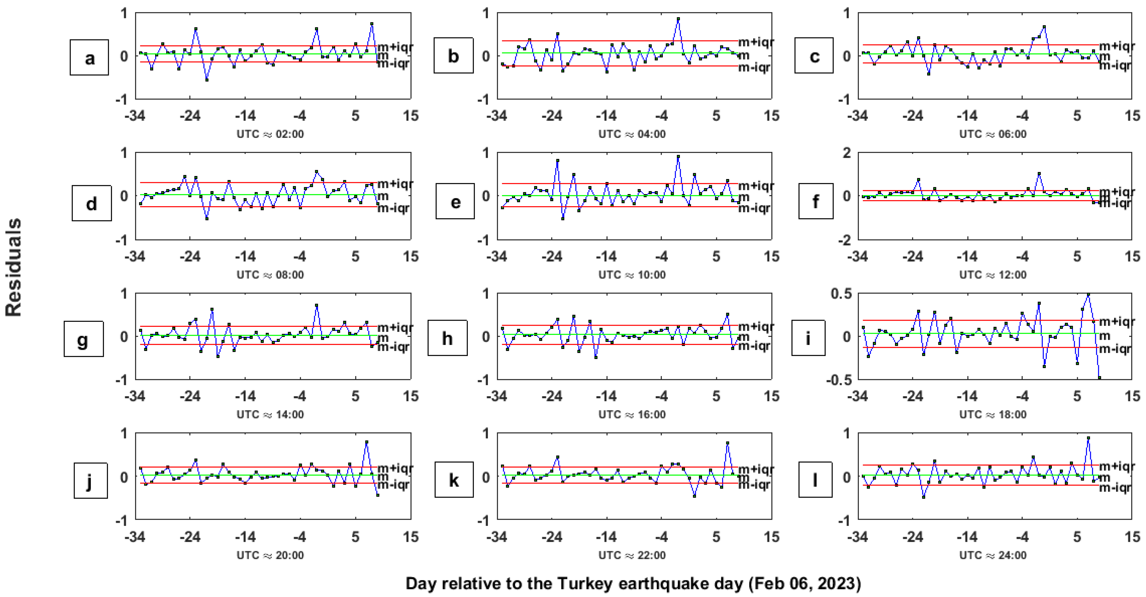
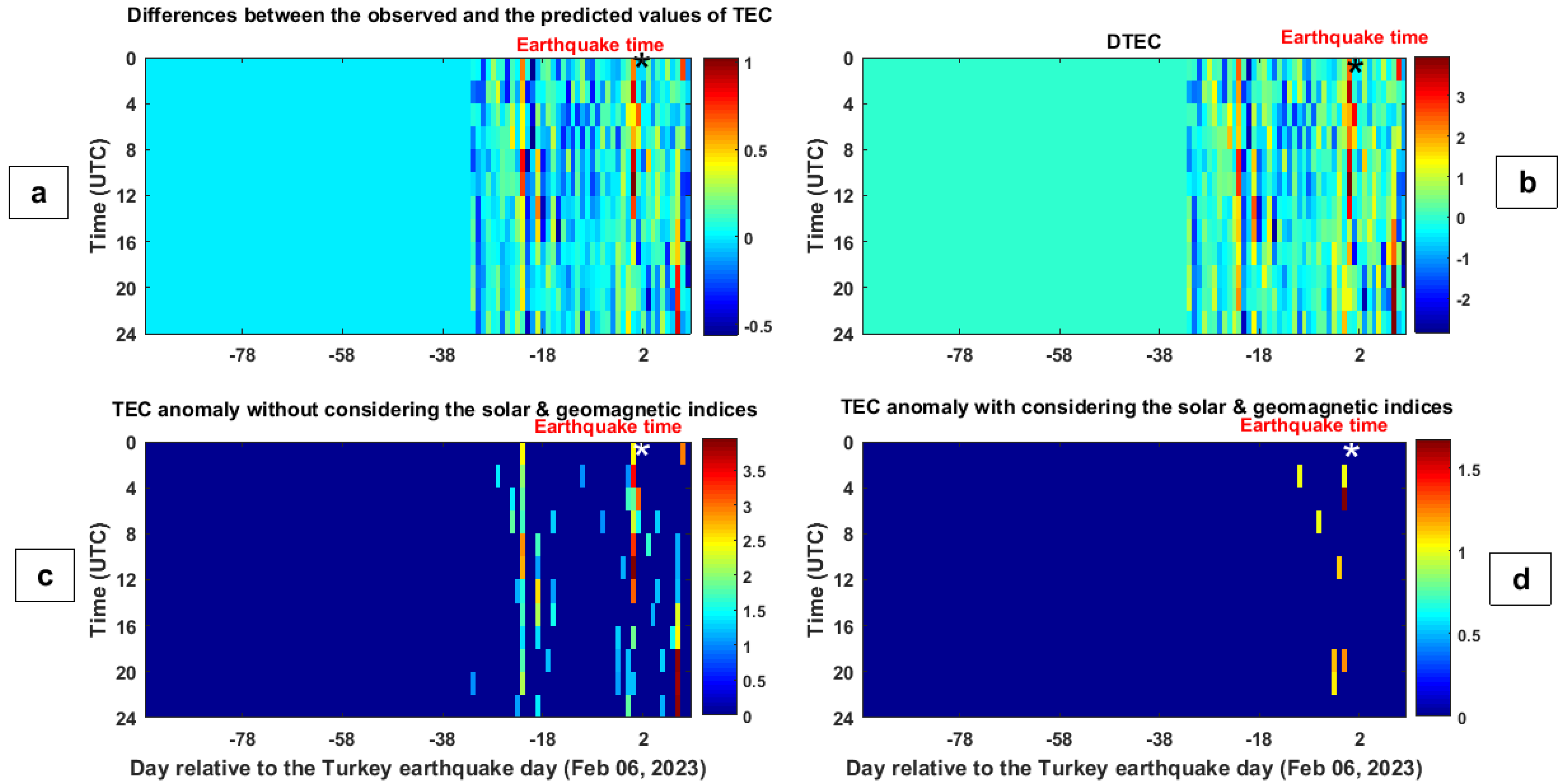
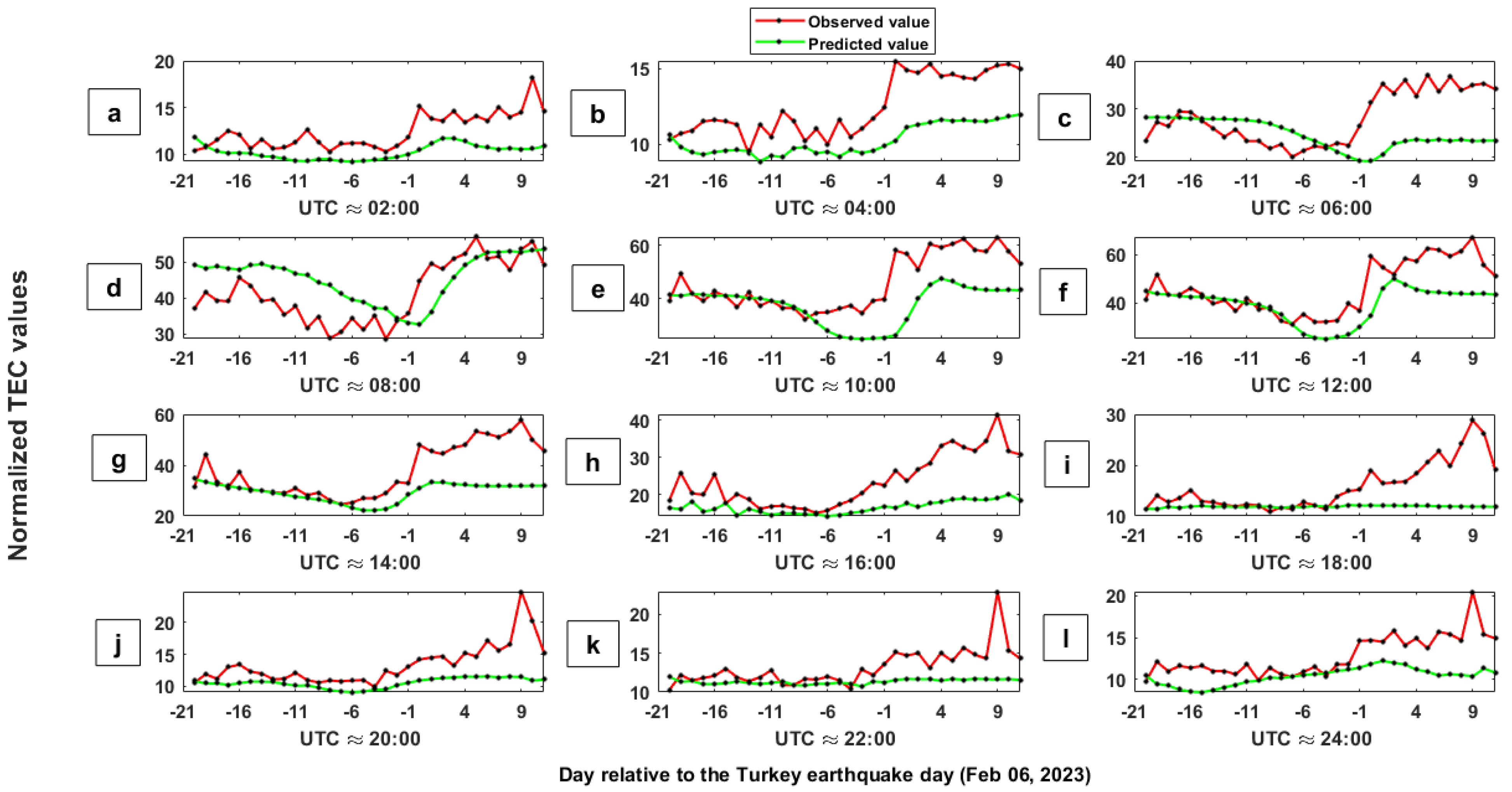
In order to implement the ANN method, 60% of the data were considered as training data and the remaining 40% as test data. Figure 6a–l show the observed normalized TEC values (red curve) and the TEC values predicted by the ANN-MLP method (green curve) in the time period of test data at a time interval of 2 h according to the time resolution of the TEC data. Panels a to l in Figure 7 indicate the time series of the error values obtained via differences between estimated and observed TEC values when applying the ANN method during the test data at a different UTC. The x-axis indicates the day relative to the Turkey earthquake (6 February 2023) day. The horizontal red lines represent the lower and upper bounds ( m ± i q r ). The horizontal green line shows the median value (m). The results shown in Figure 7 are illustrated as a 2-D image in Figure 8a. By calculating the deviation of TEC values from the permissible limits defined using Equation (3), DTEC values are shown in Figure 8b. Figure 8c shows DTEC values when D T E C > 1 . Seismic TEC anomalies detected using the ANN-MLP method in quiet solar–geomagnetic conditions (F10.7 < 180 SFU, |Dst| ≤ 20 nT, ap < 20 nT, and Kp < 3 nT) are given in Figure 8d. By using this predictor, sharp anomalies are observed in TEC values in 1, 2, 3, 6, and 10 days before the earthquake. The highest amount of this anomaly with a value of 67.5% is seen 1 day before the event at 06:00 UTC. The characteristics of other anomalies observed by the ANN method are presented in Table 1. The observed anomalies emphasize that the ANN method, based on the previous patterns in the time series, has predicted the parameter value with a large difference compared with the observed value, and the reason for this can be the existence of an abnormal event at the time in question. If the solar and geomagnetic conditions are quiet, it can probably be related to the upcoming earthquake.
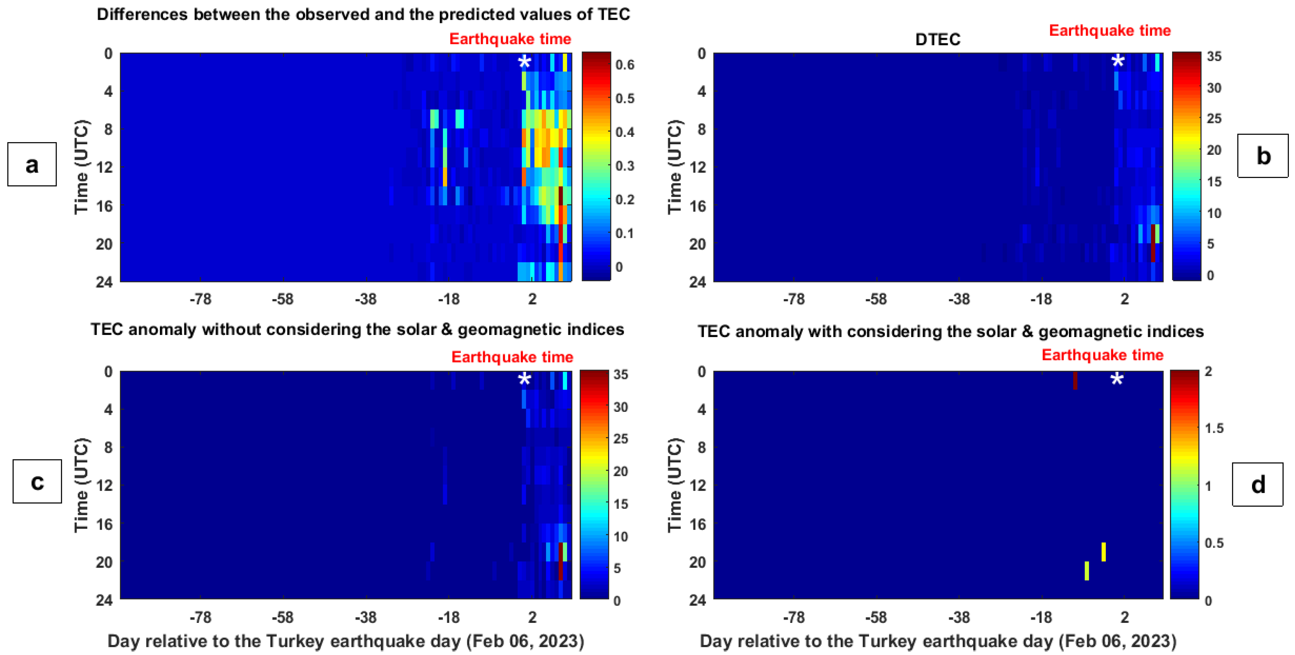
LSTM is implemented as a special type of RNN neural network to detect seismic TEC anomalies. For this purpose, 70% of the data are considered as the training part and 30% for use in the testing and prediction stage. Figure 9a–l represent the observed TEC values (red curve) and the TEC values predicted by the LSTM algorithm (green curve) in the time period of the test data at a time interval of 2 h according to the time resolution of the TEC data. Figure 10a–l show the time series of the differences between the estimated and observed TEC values after implementing the LSTM method in the time period of the test data at different universal times. These obtained difference values are displayed as an image in Figure 11a. In the next step, the DTEC values are obtained according to difference values and Equation (3) (Figure 11b). Figure 11c shows the DTEC values that exceed the defined threshold D T E C > 1 . In the last step, only DTEC values are displayed that are detected during quiet times in terms of solar and geomagnetic conditions (Figure 11d). A striking anomaly is detected 10 days prior to the earthquake at 02:00 UTC when the TEC parameter exceeds the upper limit with a value of 1.1%.
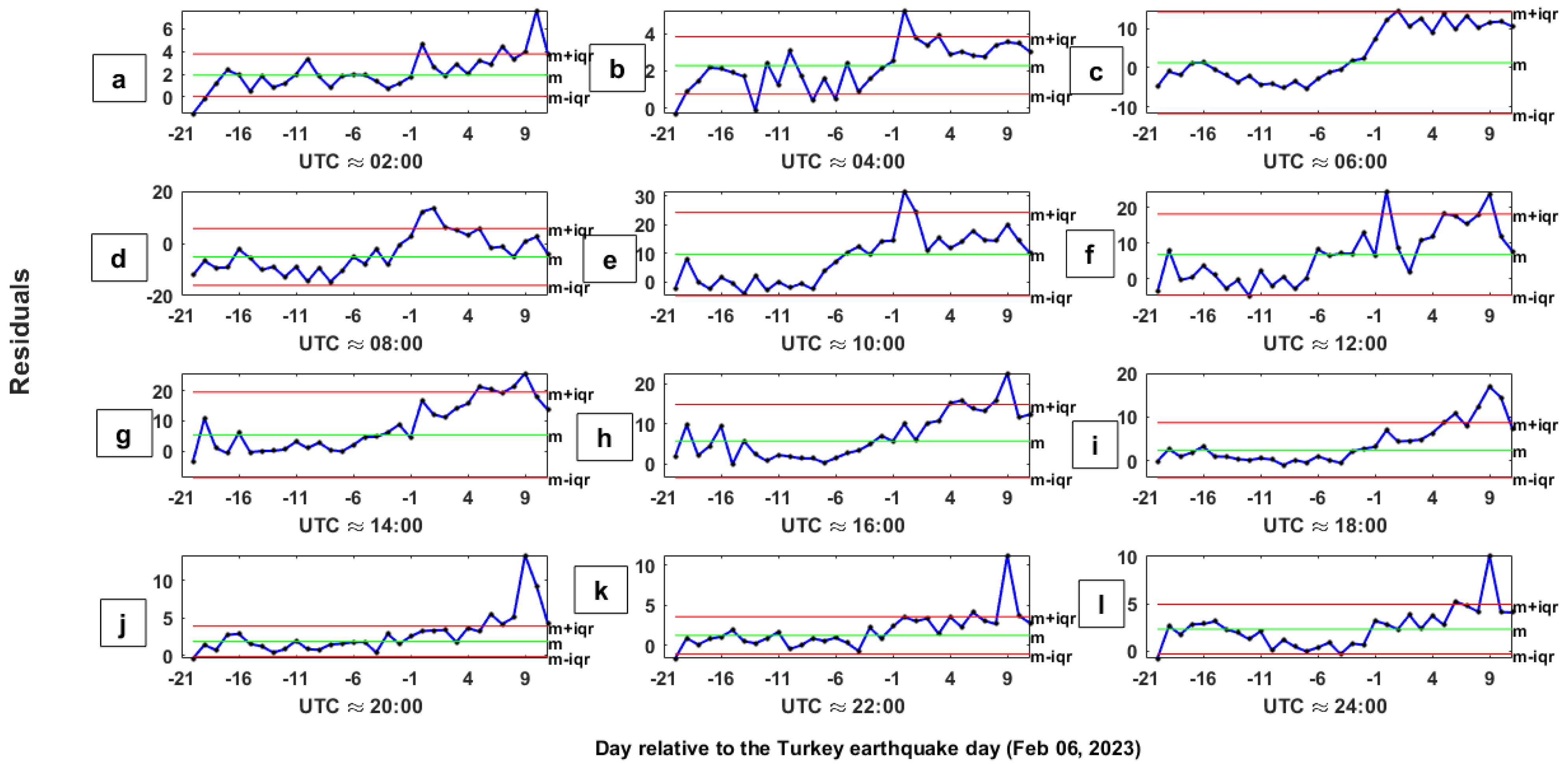
In order to implement the ACO algorithm, 60% of the data are used to build the state matrix and create the feature space [33]. It should be noted that the dimensions and nature of the state matrix play a significant role in finding nonlinear patterns in the data. The red and green curves in panels a–l of Figure 12, respectively, show the observed and predicted TEC values by the ACO algorithm in the 109-day period studied. Figure 13 shows the difference between observed and predicted values in a 2 h time resolution of the TEC data in different panels. In each panel, by calculating the median and interquartile values, the upper and lower boundaries are displayed with red horizontal lines. Figure 14a shows the results of Figure 13 as an image. If the deviation of DTEC values from the defined permissible limits is calculated, the results can be seen in Figure 14b. Figure 14c shows DTEC values greater than 1. Figure 14d from the DTEC values observed in Figure 14c shows only the values detected in quiet conditions in terms of solar and geomagnetic conditions. Figure 14d indicates that the TEC values in 3 (20:00 UT), 7 (22:00 UT), and 10 (2:00 UT) days before the earthquake, with values of 25%, 14.3%, and 100%, exceeded the defined permissible limits.

5. Discussion

It should be noted that only ionospheric anomalies in quiet solar–geomagnetic conditions can have the potential of seismic anomalies. Due to the complexities of solar–geomagnetic activities, it has not been possible to distinguish seismic anomalies from ionospheric anomalies caused by high solar and geomagnetic activities.
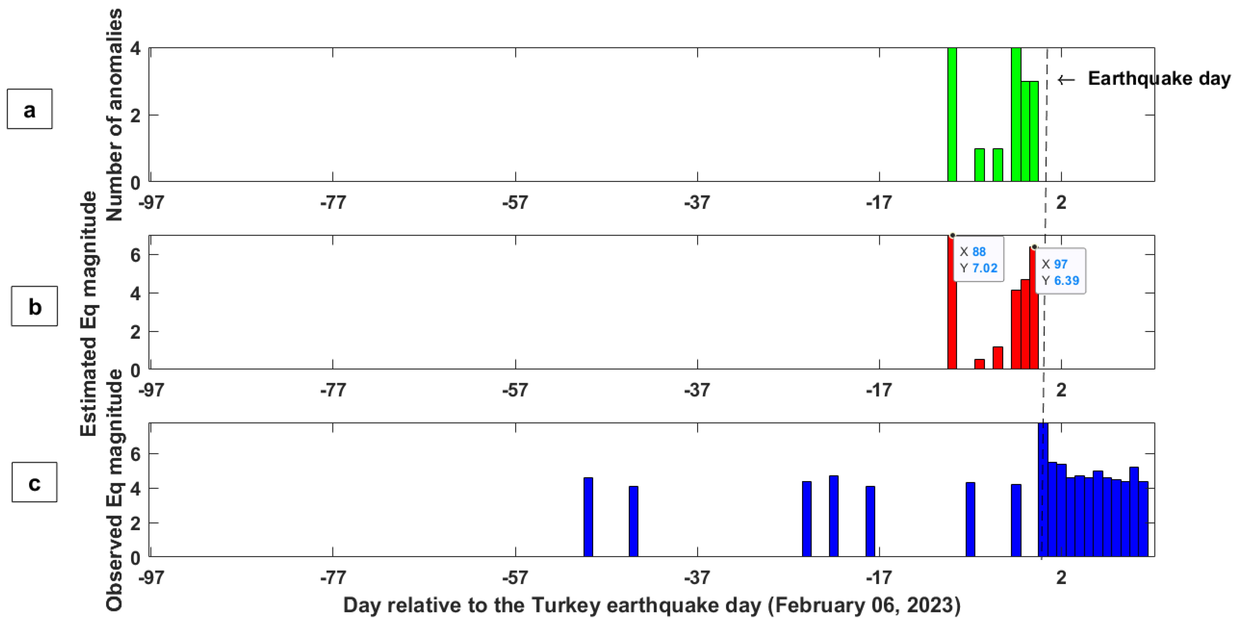
The median method emphasizes the anomalies observed between 1 and 3 days before the earthquake. Kalman filter, ANN, and ACO methods, while confirming the anomalies observed by the median method, have detected new anomalies 5, 6, 7, and 10 days before the earthquake. LSTM as a deep-learning-based neural network method also confirms the anomaly observed in 10 days before the event using the Kalman filter, ANN, and ACO methods. Therefore, by combining the results of different predictors, it is possible to emphasize the occurrence of abnormal behavior in the time series of the TEC parameter in the time interval of 10 days before the earthquake. Akhoondzadeh and Marchetti (2022) in a study [34] presented a fuzzy inference system (FIS) to integrate the results of different anomalies obtained from different precursors. Additionally, this system can be used to fuse the results of anomalies obtained from different predictors and algorithms. Figure 15a shows the number of TEC anomalies detected by different methods in the studied time period. The accumulation of TEC anomalies in the period of 10 days before the earthquake is significant. Figure 15b shows the results of integrating anomalies obtained in a fuzzy inference system and predictable earthquake magnitudes. It can be seen that the FIS system 10 days before the earthquake, by fusing the detected TEC anomalies, predicts an earthquake with a magnitude of 7.02 in the forthcoming days. Figure 15c shows the time series of the maximum recorded magnitude of earthquakes greater than 4.0, by USGS in the studied time period. In another paper [19], by combining the anomalies detected by different lithospheric, atmospheric, and ionospheric precursors, in a fuzzy inference system [31], it has been shown that the approximate magnitude of the earthquake was predictable from about 10 to 1 day before the main shock. In a previous paper [19], it was seen that from about 10 days preceding the earthquake, the potential anomalies are detected in all layers (lithosphere, atmosphere, and ionosphere). In the lithosphere, clear anomalies were observed 8 days before the event that could be related to the high seismic activities that led to the release of some gases [35], positive holes [36], or radon [37] in the atmosphere. It is clear that the effects of these gases as the formation of plasma bubbles appear as ionospheric anomalies [38]. However, due to the lack of a proven lithospheric–atmospheric–ionospheric coupling (LAIC) mechanism, it will be challenging to justify the time lag of anomalies detected by different algorithms. In the mentioned article [19], the results of the atmospheric precursors were more reliable, but in this study, the results of the TEC ionospheric precursor in comparison with the results of swarm precursors in the paper [19] are better and acknowledge the results of the previous article.

6. Conclusions

As mentioned in the previous sections, since the behavior of TEC time series is nonstationary and nonlinear, in order to detect seismic anomalies, it is necessary to use pattern recognition methods based on machine learning algorithms. To achieve this goal, in this study, five methods, including median, Kalman filter, ANN-MLP, LSTM, and ACO, were used; in other words, a multipredictor analysis was performed. By using these various methods and detecting anomalies with different patterns and behaviors, it is possible to discuss seismic TEC anomalies with lower uncertainty. Therefore, to create an efficient earthquake early warning system, it is recommended to analyze several precursors and several predictors together. If the use of anomaly detection algorithms in time series is limited, it is recommended to use algorithms that are more sensitive to nonlinear and complex behaviors in the data. The results of anomalies detected by different predictors in this paper confirm the observations of another paper [19] with a different method. For future works, it is suggested to implement other methods of anomaly detection based on deep learning. By using the Google Earth Engine and Giovanni platforms, it is possible to increase the number of precursors, and while reducing uncertainty, according to the sequence of observed anomalies, a robust mechanism for LAIC can be proposed. Additionally, if the data of GPS stations close to the study area are available, a better analysis of the anomalies can be performed due to the better spatial and temporal resolution of the GPS data. The main goal of this article is to show that since the behavior of ionospheric precursors is complex and nonlinear, it is necessary to use different classical and intelligent predictor algorithms. According to the capabilities of each of the predictors, they can detect different possible seismic anomalies. It is clear that the anomalies detected by a method, such as mean and median, are different from a method, such as the artificial neural network. In the neural network algorithm itself, different results are obtained by changing parameters, such as the number of hidden layers, the number of neurons, and inputs. Therefore, it is necessary to propose methods for fusing the results of these predictors and detecting seismic anomalies with high probability in future studies. In this case, the uncertainty in detected anomalies and false alarms are reduced. It is important to mention that the results of this article can be effective in proving and justifying a robust LAIC mechanism and relating anomalies observed in different layers to each other before the occurrence of large earthquakes.

Funding

This research received no external funding.

Data Availability Statement

GIM-TEC satellite data are freely available from the NASA https/ftp server at ftp://cddis.gsfc.nasa.gov/pub/gps/products/ionex/ (accessed on 4 May 2023). The global USGS earthquake catalogue can be accessed at https://earthquake.usgs.gov/earthquakes (accessed on 4 May 2023). The fault map shown in Figure 1 was obtained from the European Fault-Source Model 2020 (EFSM20) [20].

Acknowledgments

The author would like to acknowledge the NASA Jet Propulsion Laboratory for the GIM-TEC and solar and geomagnetic indices.

Conflicts of Interest

The author declares no conflict of interest. The funders had no role in the design of the study; in the collection, analyses, or interpretation of data; in the writing of the manuscript; or in the decision to publish the results.

References

  1. Garmaise, M.J.; Moskowitz, T.J. Catastrophic Risk and Credit Markets. J. Financ. 2009, 64, 657–707. [Google Scholar] [CrossRef]
  2. Mignan, A.; Ouillon, G.; Sornette, D.; Freund, F. Global Earthquake Forecasting System (GEFS): The Challenges Ahead. Eur. Phys. J. Spec. Top. 2021, 230, 473–490. [Google Scholar] [CrossRef]
  3. De Santis, A.; Marchetti, D.; Pavón-Carrasco, F.J.; Cianchini, G.; Perrone, L.; Abbattista, C.; Alfonsi, L.; Amoruso, L.; Campuzano, S.A.; Carbone, M.; et al. Precursory Worldwide Signatures of Earthquake Occurrences on Swarm Satellite Data. Sci. Rep. 2019, 9, 20287. [Google Scholar] [CrossRef] [Green Version]
  4. Marchetti, D.; De Santis, A.; Campuzano, S.A.; Zhu, K.; Soldani, M.; D’Arcangelo, S.; Orlando, M.; Wang, T.; Cianchini, G.; Di Mauro, D.; et al. Worldwide Statistical Correlation of Eight Years of Swarm Satellite Data with M5.5+ Earthquakes: New Hints about the Preseismic Phenomena from Space. Remote Sens. 2022, 14, 2649. [Google Scholar] [CrossRef]
  5. Marchetti, D.; Zhu, K.; Yan, R.; ZeRen, Z.; Shen, X.; Chen, W.; Cheng, Y.; Fan, M.; Wang, T.; Wen, J.; et al. Ionospheric Effects of Natural Hazards in Geophysics: From Single Examples to Statistical Studies Applied to M5.5+ Earthquakes. In Proceedings of the 4th International Electronic Conference on Geosciences, Online, 1–15 December 2022; MDPI: Basel, Switzerland, 2022. [Google Scholar]
  6. Chen, Y.-I.; Huang, C.-S.; Liu, J.-Y. Statistical Evidences of Seismo-Ionospheric Precursors Applying Receiver Operating Characteristic (ROC) Curve on the GPS Total Electron Content in China. J. Asian Earth Sci. 2015, 114, 393–402. [Google Scholar] [CrossRef]
  7. Genzano, N.; Filizzola, C.; Hattori, K.; Pergola, N.; Tramutoli, V. Statistical Correlation Analysis Between Thermal Infrared Anomalies Observed from MTSATs and Large Earthquakes Occurred in Japan (2005–2015). J. Geophys. Res. Solid Earth 2021, 126, e2020JB020108. [Google Scholar] [CrossRef]
  8. Yan, R.; Parrot, M.; Pinçon, J.-L. Statistical Study on Variations of the Ionospheric Ion Density Observed by DEMETER and Related to Seismic Activities: Ionospheric Density and Seismic Activity. J. Geophys. Res. Space Phys. 2017, 122, 12421–12429. [Google Scholar] [CrossRef] [Green Version]
  9. Akhoondzadeh, M. Advances in Seismo-LAI Anomalies Detection within Google Earth Engine (GEE) Cloud Platform. Adv. Space Res. 2022, 69, 4351–4357. [Google Scholar] [CrossRef]
  10. Christodoulou, V.; Bi, Y.; Wilkie, G. A Tool for Swarm Satellite Data Analysis and Anomaly Detection. PLoS ONE 2019, 14, e0212098. [Google Scholar] [CrossRef]
  11. Chen, H.; Han, P.; Hattori, K. Recent Advances and Challenges in the Seismo-Electromagnetic Study: A Brief Review. Remote Sens. 2022, 14, 5893. [Google Scholar] [CrossRef]
  12. De Santis, A.; Marchetti, D.; Spogli, L.; Cianchini, G.; Pavón-Carrasco, F.J.; Franceschi, G.D.; Di Giovambattista, R.; Perrone, L.; Qamili, E.; Cesaroni, C.; et al. Magnetic Field and Electron Density Data Analysis from Swarm Satellites Searching for Ionospheric Effects by Great Earthquakes: 12 Case Studies from 2014 to 2016. Atmosphere 2019, 10, 371. [Google Scholar] [CrossRef] [Green Version]
  13. Xiong, P.; Marchetti, D.; De Santis, A.; Zhang, X.; Shen, X. SafeNet: SwArm for Earthquake Perturbations Identification Using Deep Learning Networks. Remote Sens. 2021, 13, 5033. [Google Scholar] [CrossRef]
  14. Essam, Y.; Kumar, P.; Najah Ahmed, A.; Ary Murti, M.; El-Shafie, A. Exploring the reliability of different artificial intelligence techniques in predicting earthquake for Malaysia. Soil Dyn. Earthq. Eng. 2021, 147, 106826. [Google Scholar] [CrossRef]
  15. Portillo, A.; Moya, L. Seismic Risk Regularization for Urban Changes Due to Earthquakes: A Case of Study of the 2023 Turkey Earthquake Sequence. Remote Sens. 2023, 15, 2754. [Google Scholar] [CrossRef]
  16. Marhain, S.; Ahmed, A.N.; Murti, M.A.; Kumar, P.; El-Shafie, A. Investigating the application of artificial intelligence for earthquake prediction in Terengganu. Nat. Hazards 2021, 108, 977–999. [Google Scholar] [CrossRef]
  17. Li, S.; Wang, X.; Tao, T.; Zhu, Y.; Qu, X.; Li, Z.; Huang, J.; Song, S. Source Model of the 2023 Turkey Earthquake Sequence Imaged by Sentinel-1 and GPS Measurements: Implications for Heterogeneous Fault Behavior along the East Anatolian Fault Zone. Remote Sens. 2023, 15, 2618. [Google Scholar] [CrossRef]
  18. Murti, M.A.; Junior, R.; Ahmed, A.N.; Elshafie, A. Earthquake multi-classification detection based velocity and displacement data filtering using machine learning algorithms. Sci. Rep. 2022, 12, 21200. [Google Scholar] [CrossRef]
  19. Akhoondzadeh, M.; Marchetti, D. Study of the Preparation Phase of Turkey’s Powerful Earthquake (6 February 2023) by a Geophysical Multi-Parametric Fuzzy Inference System. Remote Sens. 2023, 15, 2224. [Google Scholar] [CrossRef]
  20. Basili, R.; Danciu, L.; Beauval, C.; Sesetyan, K.; Vilanova, S.; Adamia, S.; Arroucau, P.; Atanackov, J.; Baize, S.; Canora, C.; et al. European Fault-Source Model 2020 (EFSM20): Online Data on Fault Geometry and Activity Parameters; Istituto Nazionale Di Geofisica e Vulcanologia (INGV): Rome, Italy, 2022. [Google Scholar] [CrossRef]
  21. Akhoondzadeh, M. Anomalous TEC variations associated with the powerful Tohoku earthquake of 11 March 2011. Nat. Hazards Earth Syst. Sci. 2012, 12, 1453–1462. [Google Scholar] [CrossRef] [Green Version]
  22. Liu, J.Y.; Chuo, Y.J.; Shan, S.J.; Tsai, Y.B.; Chen, Y.I.; Pulinets, S.A.; Yu, S.B. Pre-earthquake-ionospheric anomalies registered by continuous GPS TEC. Ann. Geophys. 2004, 22, 1585–1593. [Google Scholar] [CrossRef] [Green Version]
  23. Akhoondzadeh, M. A MLP neural network as an investigator of TEC time series to detect seismo-ionospheric anomalies. Adv. Space Res. 2013, 51, 2048–2057. [Google Scholar] [CrossRef]
  24. Akhoondzadeh, M.; De Santis, A.; Marchetti, D.; Shen, X. Swarm-TEC Satellite Measurements as a Potential Earthquake Precursor Together with Other Swarm and CSES Data: The Case of Mw7.6 2019 Papua New Guinea Seismic Event. Front. Earth Sci. 2022, 10, 820189. [Google Scholar] [CrossRef]
  25. Akhoondzadeh, M.; De Santis, A. Is the Apparent Correlation between Solar-Geomagnetic Activity and Occurrence of Powerful Earthquakes a Casual Artifact? Atmosphere 2022, 13, 1131. [Google Scholar] [CrossRef]
  26. Klobuchar, J.A. Ionospheric Time-Delay Algorithm for Single-Frequency GPS Users. IEEE Trans. Aerosp. Electron. Syst. 1987, 23, 325–331. [Google Scholar] [CrossRef]
  27. Prieto-Cerdeira, R.; Orús-Pérez, R.; Breeuwer, E.; Lucas-Rodríguez, R.; Falcone, M. Innovation: The European Way. Performance of the Galileo Single-Frequency Ionospheric Correction during In-Orbit Validation. GPSworld 2014, 25, 53–58. [Google Scholar]
  28. Yuan, Y.; Wang, N.; Li, Z.; Huo, X. The BeiDou global broadcast ionospheric delay correction model (BDGIM) and its preliminary performance evaluation results. J. Inst. Navig. 2019, 66, 55–69. [Google Scholar] [CrossRef] [Green Version]
  29. Dobrovolsky, I.P.; Zubkov, S.I.; Miachkin, V.I. Estimation of the Size of Earthquake Preparation Zones. Pure Appl. Geophys. 1979, 117, 1025–1044. [Google Scholar] [CrossRef]
  30. Akhoondzadeh, M.; De Santis, A.; Marchetti, D.; Piscini, A.; Cianchini, G. Multi Precursors Analysis Associated with the Powerful Ecuador (MW = 7.8) Earthquake of 16 April 2016 Using Swarm Satellites Data in Conjunction with Other Multi-Platform Satellite and Ground Data. Adv. Space Res. 2018, 61, 248–263. [Google Scholar] [CrossRef] [Green Version]
  31. Akhoondzadeh, M.; De Santis, A.; Marchetti, D.; Wang, T. Developing a Deep Learning-Based Detector of Magnetic, Ne, Te and TEC Anomalies from Swarm Satellites: The Case of Mw 7.1 2021 Japan Earthquake. Remote Sens. 2022, 14, 1582. [Google Scholar] [CrossRef]
  32. Dorigo, M. Optimization, Learning, and Natural Algorithms. Ph.D. Thesis, Politecnico di Milano, Milano, Italy, 1992. [Google Scholar]
  33. Akhoondzadeh, M. Ant Colony Optimization detects anomalous aerosol variations associated with the Chile earthquake of 27 February 2010. Adv. Space Res. 2015, 55, 1754–1763. [Google Scholar] [CrossRef]
  34. Akhoondzadeh, M.; Marchetti, D. Developing a Fuzzy Inference System Based on Multi-Sensor Data to Predict Powerful Earthquake Parameters. Remote Sens. 2022, 14, 3203. [Google Scholar] [CrossRef]
  35. Enomoto, Y. Coupled Interaction of Earthquake Nucleation with Deep Earth Gases: A Possible Mechanism for Seismo-Electromagnetic Phenomena. Geophys. J. Int. 2012, 191, 1210–1214. [Google Scholar] [CrossRef] [Green Version]
  36. Freund, F.; Ouillon, G.; Scoville, J.; Sornette, D. Earthquake Precursors in the Light of Peroxy Defects Theory: Critical Review of Systematic Observations. Eur. Phys. J. Spec. Top. 2021, 230, 7–46. [Google Scholar] [CrossRef]
  37. Pulinets, S.; Ouzounov, D. Lithosphere–Atmosphere–Ionosphere Coupling (LAIC) Model—An Unified Concept for Earthquake Precursors Validation. J. Asian Earth Sci. 2011, 41, 371–382. [Google Scholar] [CrossRef]
  38. Kuo, C.L.; Lee, L.C.; Huba, J.D. An Improved Coupling Model for the Lithosphere-Atmosphere-Ionosphere System. J. Geophys. Res. Space Phys. 2014, 119, 3189–3205. [Google Scholar] [CrossRef]
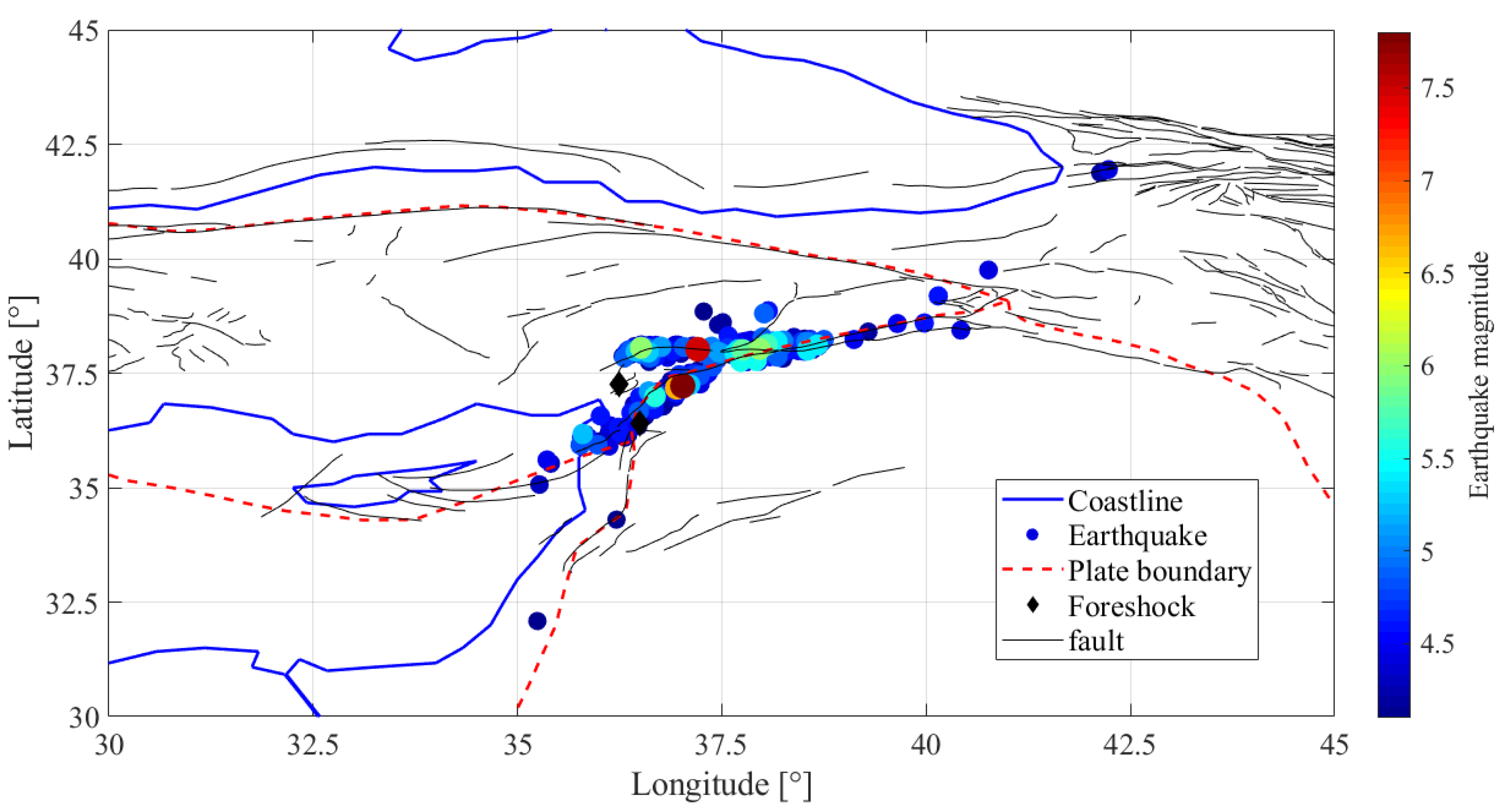
Figure 1. Geographic location of the registered earthquakes with a magnitude greater than 4.1 from 6 to 17 February 2023. The plate boundaries are shown as red dashed lines and the two foreshocks as black diamonds [19,20].
Remotesensing 15 03061 g001
Figure 2. An overview of the steps of implementing the methods in this study.
Remotesensing 15 03061 g002
Figure 3. Geomagnetic indices of (a) Kp, (b) ap, (c) Dst, and (d) F10.7 in the time period of 1 November 2022 to 17 February 2023. The abscissa represents the days relative to the Turkey (6 February 2023) earthquake day. A black asterisk “*” indicates the earthquake origin time. The values of geomagnetic indices are displayed in quiet conditions with green color and in nonquiet geomagnetic conditions with red color.
Remotesensing 15 03061 g003
Figure 4. Results of TEC analysis for the Turkey earthquake (6 February 2023) using the median method during the period of 1 November 2022 to 17 February 2023. (a) Variations of TEC, (b) variations of DTEC, (c) observed TEC anomalies regardless the solar–geomagnetic conditions, and (d) observed TEC anomalies by considering quiet solar–geomagnetic conditions. The x-axis represents the days relative to the earthquake day. The y-axis indicates the universal time. An asterisk “*” shows the earthquake origin time.
Remotesensing 15 03061 g004
Figure 5. Results of TEC analysis for the Turkey earthquake (6 February 2023) using the Kalman filter method during the period of 1 November 2022 to 17 February 2023. (a) Variations of TEC, (b) variations of DTEC, (c) observed TEC anomalies regardless the solar–geomagnetic conditions, and (d) observed TEC anomalies by considering quiet solar–geomagnetic conditions.
Remotesensing 15 03061 g005
Figure 6. Panels (al) represent the time series of the predicted TEC values (green curve) when implementing the ANN method and also the normalized observed TEC values (red curve) during the test data at a different UTC. The x-axis indicates the day relative to the Turkey earthquake (6 February 2023) day.
Remotesensing 15 03061 g006
Figure 7. Panels (al) represent the time series of the error values obtained via differences between estimated and observed TEC values when applying the ANN method during the test data at a different UTC. The x-axis indicates the day relative to the Turkey earthquake (6 February 2023) day. The horizontal red lines represent the lower and upper bounds ( m ± i q r ). The horizontal green line shows the median value (m).
Remotesensing 15 03061 g007
Figure 8. Results of TEC analysis for the Turkey earthquake (6 February 2023) using the ANN method during the period of 1 November 2022 to 17 February 2023. (a) Variations of TEC, (b) variations of DTEC, (c) observed TEC anomalies regardless the solar–geomagnetic conditions, and (d) observed TEC anomalies by considering quiet solar–geomagnetic conditions.
Remotesensing 15 03061 g008
Figure 9. Panels (al) represent the time series of the predicted TEC values (green curve) when implementing the LSTM method and also the normalized observed TEC values (red curve) during the test data at a different UTC. The x-axis indicates the day relative to the Turkey earthquake (6 February 2023) day.
Remotesensing 15 03061 g009
Figure 10. Panels (al) represent the time series of the error values obtained via differences between estimated and observed TEC values when applying the LSTM method during the test data at a different UTC. The x-axis indicates the day relative to the Turkey earthquake (6 February 2023) day. The horizontal red lines represent the lower and upper bounds ( m ± i q r ). The horizontal green line shows the median value (m).
Remotesensing 15 03061 g010
Figure 11. Results of TEC analysis for the Turkey earthquake (6 February 2023) using the LSTM method during the period of 1 November 2022 to 17 February 2023. (a) Variations of TEC, (b) variations of DTEC, (c) observed TEC anomalies regardless the solar–geomagnetic conditions, and (d) observed TEC anomalies by considering quiet solar–geomagnetic conditions.
Remotesensing 15 03061 g011
Figure 12. Panels (al) represent the time series of the predicted TEC values (green curve) when implementing the ACO method and also the normalized observed TEC values (red curve) during the test data at a different UTC. The x-axis indicates the day relative to the Turkey earthquake (6 February 2023) day.
Remotesensing 15 03061 g012
Figure 13. Panels (al) represent the time series of the error values obtained via differences between estimated and observed TEC values when applying the ACO method during the test data at a different UTC. The x-axis indicates the day relative to the Turkey earthquake (6 February 2023) day. The horizontal red lines represent the lower and upper bounds ( m ± i q r ). The horizontal green line shows the median value (m).
Remotesensing 15 03061 g013
Figure 14. Results of TEC analysis for the Turkey earthquake (6 February 2023) using the ACO method during the period of 1 November 2022 to 17 February 2023. (a) Variations of TEC, (b) variations of DTEC, (c) observed TEC anomalies regardless the solar–geomagnetic conditions, and (d) observed TEC anomalies by considering quiet solar–geomagnetic conditions.
Remotesensing 15 03061 g014
Figure 15. (a) Variation in the number of detected anomalies using different methods (green bars), (b) variation in the predicted earthquake magnitude (red bars), and (c) variation in the registered earthquake magnitude (blue bars) for the Turkey earthquake (6 February 2023) from 1 November 2022 to 17 February 2023. In all panels, the x-axis represents the day relative to the earthquake day indicated as a vertical dotted line.
Remotesensing 15 03061 g015
Table 1. Details of observed anomalies using different predictors. Day is given prior to the event. DTEC is calculated according to Equation (3).
MethodAnomalous Day and TimeDTEC
DayUTC
Median−116:0039.8%
18:0048.6%
−216:0049.6%
18:0037.1%
−316:004.1%
Kalman filter−16:0058.7%
−28:003.7%
12:006.2%
−320:0018.9%
22:0011%
−54:0030.2%
−104:0038.9%
ANN-MLP−16:0067.5%
8:000.8%
20:0021.2%
−212:0011.7%
−320:0014.3%
22:005.3%
−68:000.3%
−104:001.5%
LSTM−102:001.1%
ACO−320:0025%
−722:0014.29%
−102:00100%
Disclaimer/Publisher’s Note: The statements, opinions and data contained in all publications are solely those of the individual author(s) and contributor(s) and not of MDPI and/or the editor(s). MDPI and/or the editor(s) disclaim responsibility for any injury to people or property resulting from any ideas, methods, instructions or products referred to in the content.