Article

Sequential Generation of Multi-GNSS Multi-Frequency PPP-RTK Products and Their Performance Using the EUREF Permanent GNSS Network

by
Hans Daniel Platz
Physical and Satellite Geodesy, Technical University of Darmstadt, Franziska-Braun-Str. 7, 64287 Darmstadt, Germany
Remote Sens. 2023, 15(11), 2792; https://doi.org/10.3390/rs15112792
Submission received: 14 April 2023 / Revised: 19 May 2023 / Accepted: 24 May 2023 / Published: 27 May 2023
(This article belongs to the Special Issue Precise Point Positioning (PPP) Based on Multi-GNSS)

Abstract

:
In the classic Precise Point Positioning (PPP) approach, observations of Global Navigation Satellite Systems (GNSS) are processed at the network level to generate satellite clocks and positions. This information can be used to enable accurate point positioning for a single GNSS receiver. In the PPP Real-Time Kinematic (PPP-RTK) approach, satellite phase biases are considered as well, enabling ambiguity resolution at the network and user levels. In this research, 30 s multi-frequency raw GPS, Galileo, and BDS-2/3 observations are processed at the network and user levels in a sequential Kalman filter. PPP-RTK enabling products are generated for up to five frequencies, and ambiguity resolution is performed at the network and user levels using a flexible ambiguity reparameterization approach, comparable to wide- and narrow-laning, which has shown to yield a significantly improved single epoch coordinate solution when multi-frequency observations are available. Different assumptions regarding the time stability of receiver and satellite phase biases have been made and compared. The availability of a precise user coordinate solution when multi-frequency and dual-frequency observations are processed is assessed and compared. A precise ambiguity-fixed solution is available in three epochs or fewer in 77% of all cases with an average of 24 visible satellites for static and kinematic receivers when multi-frequency observations are processed. When only dual-frequency observations are considered, a fixed solution is available in seven epochs or fewer in 71% of all cases. The fastest fixed solution was found in two epochs with multi-frequency observations and in six epochs with dual-frequency observations. Estimating a reference phase clock did not lead to an improvement in the coordinate solution. The findings indicate that a fixed solution can potentially be found faster than often suggested, with potential for further improvement when more satellites or regional atmospheric corrections are considered.

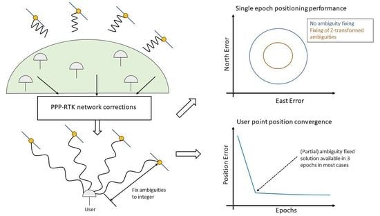
Graphical Abstract

1. Introduction

Modernized GNSS provide an increasing number of available signals and channels, leading to an increasing interest in processing all available signal-channel combinations, creating network information that gives the user of those products the most amount of freedom in the sense that they are free to choose what signals and channels they process in their applications. Processing observations from a multitude of different signals and channels requires explicit handling of existing rank deficiencies in the observations. For a critical review of methods to eliminate rank deficiencies in GNSS networks for PPP and PPP-RTK, see [1]. In [2], an in-depth review of the often-used Common Clocks (CC) model often used to eliminate rank deficiencies and generate PPP(-RTK) products is presented, which is implemented and adapted here. More specifically, the CC-R model is implemented and used within the scope of this paper. The CC-R model is a specific application of the CC model, where one pivot receiver defines the clock and bias datum. Possible complications arising from the CC-R model within certain GNSS networks and sequential processing are presented and discussed in Section 3.1.
Multi-frequency raw observations of GPS, Galileo, and BDS-2/3 satellites are processed at the network and user levels. Ambiguity resolution is performed both for the network and the user, improving accuracy and reducing the time until accurate network products and user point positions are available. Of high interest is the time until a centimeter-accurate, ambiguity-fixed solution is achieved for a user of the network products. In [3], a fixed solution with centimeter accuracy was achieved after 600 s using dual-frequency GPS observations with a temporal resolution of 30 s. The authors of the previously mentioned study then investigated the time until a fixed solution is available when combining GPS and GLONASS. The time until ambiguity resolution enables centimeter accuracy is reduced to an average of 6 min, and in more than 50% of cases, to under 5 min. Here, interpolated ionospheric slant delay corrections from the network receivers were used to enable integer ambiguities for GLONASS satellites. In [4], GPS and GLONASS satellites were used as well, but GLONASS ambiguities were kept as float values. The average time to first fix was around 15 min for static and 20 min for kinematic receivers. After the introduction of a functional model enabling integer ambiguities for FDMA satellite systems such as GLONASS in [5], a five-system (GPS, Galileo, BDS, QZSS, and GLONASS) analysis was performed in [6]. For a long baseline using all available systems, a centimeter-accurate point solution could be achieved in an average of 3.27 epochs when no atmospheric corrections and partial ambiguity resolution were used. It was also shown that an average of 34.7 epochs are required until the Success Rate of full ambiguity resolution is over 99.9%, even when five satellite systems are considered. Note that no QZSS and not all BDS satellites are available for GNSS receivers in Europe, as considered here.
Different assumptions regarding the time stability of the receiver and satellite phase biases are implemented and compared in this study. In [7], the Decoupled Clocks model has been introduced: Here a separate clock offset is estimated for dual-frequency code and phase observations. In other studies, such as [8,9], the satellite phase biases are classified as wide-lane and narrow-lane biases. Here the narrow-lane biases are estimated as constant parameters, but only for time intervals of 15 min. A degradation of performance has been observed when satellite phase biases are assumed to be constant for longer time intervals. However, later in [10], narrow-lane phase biases are estimated as daily constant parameters, which has led to better positioning accuracy without impairing ambiguity resolution rates. For GPS BLOCK IIF satellites, a significant variation of the L5 phase biases, mainly due to thermal variation, compared to the L1 and L2 biases has been observed [11,12]. To investigate the effects of different assumptions regarding the time stability of phase biases further, two methods are implemented and compared. In one approach, all phase biases are assumed to be static parameters, excluding satellite GPS L5 phase biases, whereas in the other approach, a separate epoch-wise phase clock is estimated for all receivers and satellites.
The main purpose of this contribution is to analyze the quality of forward-filtered satellite clocks and biases for PPP-RTK and to compare the effects of different assumptions regarding the temporal stability of phase biases on the quality of the point position. Furthermore, a flexible method to introduce reparameterized ambiguities comparable to wide-lane and narrow-lane ambiguities into the functional model is presented, and the time until an ambiguity-fixed solution can be found is assessed. Ambiguity resolution is performed with the Ratio Test Integer Aperture estimation approach using the algorithm as described in [13]. When compared to the most common approach using the Success Rate and a Ratio Test, this approach should yield an integer fixed solution faster, as also investigated in the previously mentioned study.

2. Data

A regional GNSS network consisting of 32 reference stations is considered (see Figure 1). 15 stations are used as the reference network, generating the PPP-RTK products relevant to the user. The other 17 stations then use the generated network products to compute their point positions. All reference stations are part of the EUREF Permanent GNSS network [14]. Daily observations with a sampling of 30 s of day 293 in the year 2022 are considered. The presented methods here can all be applied to observations with a higher sampling rate. A discussion of problems and opportunities arising when high-rate observations are processed is given in Section 5. A complete list of all considered reference stations is also given in Figure 1. An overview of the processed GNSS and signal-channel combinations is given in Table 1. Note that the receivers can be divided into receiver types A and B based on the tracking mode used to observe the different signals. This will be addressed further in Section 3.1.
The reference coordinates of all stations have been obtained with the EUREF reference frame solution [15]. Satellite orbits have been fixed to precise values, using the final CODE orbits [16]. The PPP-RTK products generated in the scope of this work are thus satellite clocks and biases. At the user level, the same satellite orbits are used as at the network level.

3. Methods

In Section 3.1, the functional model of the network and user is presented. This entails the observation equations of the code and phase measurements, and the handling of rank deficiencies in the resulting design matrix compatible with sequential processing. Then, in Section 3.2, the sequential processing scheme is presented. This includes specific properties of the processing, including the narrow-lane and wide-lane implementations, the process noise of the parameters, and details of the method of ambiguity resolution.

3.1. Functional Model

In the case of Code Division Multiple Access (CDMA), the linearized phase and code observations for a receiver r , satellite s of a GNSS A , and signal j at epoch i can be formulated according to, e.g., [17] with
E Δ φ r , j s , A i = k r s , A T i · Δ x r i + m ε r s , A · Z w i + d t r i + λ j · N r , j s , A + δ r , j A i δ j s , A i d t s , A i μ j A · I r s , A ( i ) E Δ ρ r , j s , A i = k r s , A T i · Δ x r i + m ε r s , A · Z w i + d t r i + d r , j A i d t s , A i d j s , A i + μ j A · I r s , A ( i )
Here, E ( · ) denotes the expected value of the inherently stochastic observations. Note that it is assumed that the observations have been corrected apriori with appropriate models (see, e.g., [18]); thus, the corrected effects are excluded. Furthermore, the observation equations have been modified to include the notation of the GNSS. It is assumed that different GNSS and signals have different receiver codes and phase biases, while the receiver clock is assumed to be common for each GNSS.
The observation equations have been linearized with known satellite positions and approximate receiver coordinates. In (1), k r s , A denotes the line-of-sight vector from receiver r to satellite s, Δ x r denotes the coordinate residuals of receiver r to the linearization point, Z w is the wet tropospheric zenith delay, and m is the wet mapping function converting zenith delay to slant delay with satellite elevation ε r s , A . The receiver and satellite clock offsets are denoted by d t r and d t s , A , respectively, receiver/satellite code biases are denoted with d r , j / d j s , A , and phase biases with δ r , j / δ j s , A . Ambiguities are denoted with N r , j s , A , with the important property N r , j s , A Z , and, finally, the ionospheric slant delays are denoted with I r s , A .
The resulting design matrix of the linear system of equations is rank-deficient when formulated regarding all parameters on the right-hand side of the equation. Solving a rank-deficient system of equations can be done by applying the S-System theory [19], which can be understood as imposing restrictions of the form S T · x = 0 on the parameter vector x , eliminating the underlying rank deficiencies in the functional model. The restrictions imposed on the parameter vector that eliminate all rank deficiencies in the functional model are denoted as the S-basis.
The rank deficiencies in the design matrix of the GNSS network equations have been explicitly identified in [2] for the single GNSS case. Furthermore, an in-depth description of the CC-R S-basis, which will be used hereafter, is given in [2]. However, the following three cases require adaptations to be made for the multi-GNSS case with different receiver types: (1) For each additional GNSS introduced, one rank deficiency does not occur that otherwise occurs in the single GNSS case. More specifically, this is the rank deficiency between the receiver clock and the receiver biases, as denoted in [2], since this rank deficiency has already been eliminated by the restrictions imposed on the biases of the first GNSS. As a result, one inter-system bias (ISB) has to be estimated for each additional GNSS. (2) An additional rank deficiency occurs for Galileo satellites when different satellite code biases for the same signal, but different tracking modes, are assumed. The reason is that available receivers currently either obtain the observation in pilot-tracking mode or combined-tracking mode. The receivers can then be classified as type A and type B receivers (see Table 1) with no overlapping signals. The between-ionospheric slant delays and satellite bias rank deficiencies, as denoted in [2], then occur twice: once for the signals observed by type A receivers and once for type B. The latter additional rank deficiency is eliminated with the additional S-basis restriction on d G F s , A (see Table 2). (3) Since receivers can be classified as receiver types A or B, where the tracking of some signals is unique to one receiver type, there is no receiver that observes all existing satellite code biases. Here the pivot receiver, whose clock and biases are used as restrictions in the CC-R S-basis, is assumed to be a receiver of type A. The rank deficiencies caused by the remaining satellite code biases exclusive to type B receivers, thus not observed by the pivot receiver, are then eliminated with restrictions imposed on the biases of a pivot satellite instead.
Each additional rank deficiency requires an additional S-basis restriction. All S-basis restrictions of the CC-R model, including the previously mentioned adaptations, employed on the observation Equation (1) are given in Table 2. Introducing S-basis restrictions into the functional model changes the interpretation of the estimable parameters from their original interpretation. Estimable parameters that differ from their original interpretation in Equation (1) are denoted with a hat ( ^ ).
The resulting non-rank-deficient observation equations, which are used in this research, are then given with the following:
Phase Observations
E Δ ϕ r , j s , A = k r s , A · x r + m ε r s , A · T r + d t ^ r > 1 + d ^ r > 1 A > 1 d t ^ s , A μ j A · I ^ r s , A + λ j · N ^ r > 1 , j s > 1 , A + δ ^ r > 1 , j A δ ^ j s , A
Code Observations
Receiver Type A or Type B for common signals
E Δ ρ r , j s , A = k r s , A · x r + m ε r s , A · T r + d t ^ r > 1 + d ^ r > 1 A > 1 + d ^ r > 1 , j > 2 A d t ^ s , A d ^ j > 2 s , A + μ j A · I ^ r s , A
Receiver Type B (for GNSS with no common signal)
E Δ ρ r , j s , A = k r s , A · x r + m ε r s , A · T r + d t ^ r > 1 + d ^ r > 1 A > 1 + d ^ r > 1 , j > 2 A d t ^ s , A d ^ s > 1 , A d ^ j > 2 s > 1 , A + μ j A · I ^ r s , A
Receiver Type B (for GNSS with common signals, for signals exclusive to Type B)
E Δ ρ r , j s , A = k r s , A · x r + m ε r s , A · T r + d t ^ r > 1 + d ^ r > 1 A > 1 + d ^ r > 1 , j > 2 A d t ^ s , A d ^ j s > 1 , A + μ j A · I ^ r s , A
When representing the GNSS network as a graph by defining satellites and receivers as nodes and the observations as edges, the presented S-basis restrictions only lead to non-rank-deficient observation equations in the case where the network is connected. Here the term connected is derived from graph theory; see, e.g., [20].
More specifically, the GNSS network needs to be connected on two different frequencies, or on one code and one phase frequency. This condition needs to be satisfied at each epoch when no temporal constraints on the receiver/satellite clocks or ionospheric slant delays are imposed. Otherwise, satellite clocks will not be separatable from the ionospheric slant delays. An example to illustrate this is given in Figure 2. Furthermore, to obtain integer estimable ambiguities, the GNSS network needs to be connected on every phase signal, introducing a satellite and receiver bias, since the ambiguities used as S-basis restrictions have to be a spanning tree (ST) of the respective graph (see [21]). After initialization of the ambiguity datum, the ambiguity remains set until a receiver or satellite experiences a loss of all ambiguities, i.e., all ambiguities of this receiver or satellite are reset or stop being observed. Then, this receiver or satellite is reintroduced into the GNSS network graph with a new node, and a new datum ambiguity is introduced to complete the ST again. In order to initialize the ST that determines the ambiguity datum, the edges are weighted by the inverse of the respective satellite elevation. The ST with the least total weight then determines the choice of ambiguity datum. The rationale for weighting the edges by their respective satellite elevation is that observations from satellites with high elevation are generally more accurate, i.e., they are less affected by measurement noise and effects like multipath and are less likely to experience a cycle slip. When adding a new receiver (satellite) ambiguity as a datum ambiguity, the corresponding satellite (receiver) edge with the highest elevation is used as the ambiguity datum.

3.2. Network and User Processing

In this chapter, the methods to process the non-rank-deficient observation, as given by Equation (2), are presented. This entails the estimation of the parameters, the modeling of their temporal behavior, the stochastic modeling of the observations, and the strategy to compute the ambiguity-fixed solution.
The observations are processed sequentially with a Kalman filter. Only the forward-filtered results are considered here to analyze the implemented methods for real-time applications. Note that only the final satellite orbits used here are not eligible for real-time processing. All other information could be made available in real-time. An overview of the processing scheme is given in Figure 3. This processing scheme is valid for the network and the user. Note that at the network level, the coordinates are not estimated, but are constrained by their reference values. At the user level, receiver coordinates are estimated and, in this study, compared to their reference values afterward.

3.2.1. Time Update, Measurement Update

For the parameter estimation, regular Kalman filter equations are used, although no dynamical model for the parameters is assumed. Thus, the predicted state vector at epoch k is identical to the previously filtered state vector:
x ^ k | k 1 = x ^ k 1 | k 1 ,
with variance-covariance matrix (VCM)
P k | k 1 = P k 1 | k 1 + t · S k .
Here, S k denotes the process noise matrix of the state vector x . The state vector contains all parameters of the functional model, as defined by Equation (2). At the end of this chapter, the process noise of the parameters are summarized in Table 3. There, the variance of the process noises of all parameters is defined. S k is a diagonal matrix containing the variance of the process noise at the position of the parameter. It shall be noted that for parameters declared “epoch-wise”, a process noise is chosen high enough that the predicted state estimate does not significantly influence the filtered state estimate and low enough to not cause numerical issues. Given the linearized system of the observation Equation (2),
y k + v k = A k · x ^ k | k ,   y k ~ N 0 , R k ,
the filtered state vector and its VCM are computed with
x ^ k | k = x ^ k | k 1 + K k · y k A k · x ^ k | k 1 ,   K K = P k | k 1 · A k T · A k · P k | k 1 · A k T + R k ,
P k | k = I K k · A k · P k | k 1 · I K k · A k · P k | k 1 T + K k · R k · K k T .
Here, K K is the Kalman gain and P k | k is the VCM of the filtered state vector x ^ k | k . The VCM of the observations is denoted with R k . Observations are assumed to be uncorrelated, and the standard deviation for code and phase observations is modeled as a function of the satellite elevation, as defined in Table 3.

3.2.2. Ambiguity Resolution

After every measurement update, reparameterized ambiguities are created via an admissible Z-Transformation. Admissible Z-Transformations [22] are found for every receiver-satellite link individually using the MLAMBDA algorithm [23,24]. The reason why such a reparameterization of the ambiguities is introduced is explained hereafter and demonstrated in Example 1.
Suppose we have a float estimate a ^ k = a 1 a n T and its VCM P a ^ k a ^ k of the ambiguities at epoch k . With a suitable Z-Transformation of a ^ k , i.e., z ^ k = z 1 z n T = Z · a ^ k , it could be possible that we can fix one (or more) of the Z-Transformed ambiguities z 1 , , z n to their respective integer value with high confidence, while none of the original ambiguities a 1 , a n can be fixed. For the f float ambiguities belonging to one satellite-receiver link, it is generally possible to find an admissible Z-Transformation where f 1 ambiguities can be fixed to integers at the first epoch they are observed or shortly after, when multi-frequency GNSS observations are processed with the functional model defined by Equation (2). Those are, in the scope of this work, denoted as wide-lane ambiguities. The remaining ambiguity, which usually takes significantly longer to fix to an integer, is denoted as the narrow-lane ambiguity. The terms wide-lane and narrow-lane are commonly used in GNSS processing and refer to the effect a linear combination has on the combined wavelength of the phase observations. In a wide-lane combination, the resulting wavelength is larger than the largest original wavelength in a narrow-lane combination, the combined wavelength is shorter than any of the original wavelengths [25]. Ambiguities can be understood to be fixed to integer easier as their wavelength increases. This wavelength interpretation cannot be directly applied to the Z-Transformed ambiguities. Unlike wide- and narrow-lane linear combinations, which are based on the wavelength of the combined observations, decorrelating Z-Transformations are entirely based on the VCM of the ambiguities. The wavelengths of the ( f 1 ) ambiguities obtained by the Z-Transformation that can be fixed to integers relatively easily do not necessarily fit the original definition of wide-lane ambiguities but share the same characteristic of being easy to fix to integer, which is why they will be denoted as wide-lane ambiguities in the scope of this work. The same applies to the remaining narrow-lane ambiguity. The wavelength of this Z-Transformed ambiguity is not necessarily shorter than any of the original ambiguities but remains significantly harder to be fixed to an integer than the other reparameterized ambiguities, which is why it is denoted as the narrow-lane ambiguity in this work.
Example 1.
Reparameterization of ambiguities.
Given are the highly correlated L1, L2, and L5 float ambiguities and their VCM of a GPS satellite, as computed at the first epoch of user processing:
a ^ 1 = 17.9401 19.7336 31.7038 , P a ^ 1 a ^ 1 = 10.0195 10.0001 10.0588 10.0001 10.0444 10.1137 10.0588 10.1137 10.1858 .
With the MLAMBDA algorithm, we obtain a decorrelating Z-Transformation with
Z = 9 69 59 1 5 4 0 1 1
and the reparameterized ambiguities and their respective standard deviation read:
z ^ 1 = 670.37 ± 2.51 46.09 ± 0.15 11.97 ± 0.05 .
It can be seen that two ambiguities can be fixed to integers with high confidence instantaneously. Those are denoted as wide-lane ambiguities in the scope of this research. One ambiguity remains challenging to fix to an integer, which is here denoted as the narrow-lane ambiguity. The wide-lane ambiguities in this example can be fixed in the reparameterized ambiguity vector z ^ 1 , while no ambiguities in the original ambiguity vector a ^ 1 can be fixed. As a result, this reparameterization can decrease the number of stochastic parameters and increase the accuracy of the solution, as will be shown later.
Table 3. Overview of models and settings used for network and user processing.
ItemDescriptionItemDescription
Observations and Corrections
ObservationsRaw pseudo-range and carrier phase, signals and channels as listed in Table 1Loading EffectsSolid Earth Tide, Pole Tide corrected [26]
Ocean Loading Model FES95.2 [27]
Observation weighting * σ ε = σ 0 + 2 · σ 0 · e x p ε 30 ° · π 180 ° Relativistic Clock EffectsShapiro Effect and orbit eccentricity corrected
Elevation Mask 5 ° Station CoordinatesNetwork: Fixed to Reference Frame solution [15]
Phase Center Offset & VariationsCorrected with IGS14.atx model [28]Satellite OrbitsFixed to final Code orbit [16]
Phase Wind-UpCorrected [29]Tropospheric Mapping, Hydrostatic Zenith DelayGPT3 [30]
Satellite AttitudeNominal Yaw-Steering [31]Earth Rotation Parameters (ERP)Final Code ERP [16]
Parameter Estimation ** and Process Noises  σ 2
Receiver/Satellite Clocks σ 2 = 10 5   m 2 s (“epoch-wise”)Zenith Tropospheric Delay σ 2 = 4   m m 2 h
Receiver/Satellite Code BiasesConstant parametersIonospheric Slant Delays σ 2 = 10 5   m 2 s (“epoch-wise”)
Receiver/Satellite Phase BiasesConstant or one reference phase clock (see Section 3.2.3)
Reset in case of loss of ambiguity datum (see Section 3.2.3)
GPS satellite L5 phase bias process noise
σ 2 = 1   c y c l e 2 h in all cases
AmbiguitiesConstant along one continuous satellite arc, reset when phase observation is detected as an outlier
Ambiguity resolution (Network)Success Rate > 99%, Ratio Test < 0.5 using MLAMBDA for Integer Least Squares [23,24]Ambiguity resolution (User)Ratio Test Integer Aperture estimation [13], after wide-lane ambiguities are attempted to be fixed with Success Rate > 99% and Ratio Test < 0.5
* σ 0 = 0.3   m ( σ 0 = 0.003   m ) for code (phase) observations. Formula based on [32] with changed parameters. ** Predicted parameters at the first epoch are initialized with a high variance, to not significantly influence any following estimates.
In most cases, the integer values of the original ambiguities belonging to one receiver-satellite link remain unknown until all reparameterized ambiguities are fixed. Being able to instantaneously or near-instantaneously fix the f 1 wide-lane ambiguities for every receiver-satellite link reduces the number of parameters in the measurement update (6) and improves the accuracy of the state estimate compared to when no wide-lane ambiguities are introduced and fixed.
When introducing a reparameterization into the functional model, here a reparameterization of the ambiguities z ^ k = Z k · a ^ k , the functional model of the observation needs to be adjusted with
L k + v k = A k b A k a · Z k 1 · b ^ k Z k · a ^ k = A k b A k a · Z k 1 · b ^ k z ^ k ,
with A k a being the design matrix corresponding to the ambiguities a ^ k and A k b corresponding to all other parameters b ^ k . Instead of solving for a ^ k , we have changed the functional model to directly solve for z ^ k .
Ambiguities at the user level are attempted to be fixed using the Ratio Test Integer Aperture estimation approach according to the algorithm as described in [13], using a fixed fail rate P f = 0.5 % . Compared to the conventional approach of using the Success Rate and the Ratio Test, ambiguities are expected to be fixed faster, as the conventional approach using a fixed Success Rate and Ratio Test threshold generally makes more conservative assumptions. In conjunction with the Ratio Test Integer Aperture estimation algorithm, the resulting Integer Least Squares Problem is solved by the application of the MLAMBDA algorithm. Due to the large number of ambiguities at the network level and the computationally intensive nature of the Ratio Test Integer Aperture estimation algorithm, the ambiguities are fixed at the network level using the conventional Success Rate and Ratio Test approach. The minimum Success Rate is chosen at 99%, and the Ratio Test threshold is 0.5. For the user case, wide-lane ambiguities are first attempted to be fixed with the conventional approach, and then all remaining ambiguities, including the narrow-lane ambiguities, are attempted to be fixed with the Ratio Test Integer Aperture estimation algorithm.

3.2.3. Temporal Constraints on Phase Biases

As presented in the introduction, contradicting results have been published regarding the time stability of phase biases. With a Kalman filter implementation of the UDUC observations, different models assuming different time stability of the phase biases are easy to implement and compare. In this study, two different methods to estimate satellite and receiver phase biases both at the network and user levels are considered:
  • Phase Biases are estimated as constant parameters (constant phase biases);
  • An epoch-wise reference phase clock is introduced. All other phase biases are assumed as constant parameters relative to it (reference phase clock).
Note that, in all cases, the GPS L5 satellite phase biases are assumed to vary in time with a process noise of 1   c y c l e h , due to the variation reported in [11].
To obtain one reference phase clock for each satellite and receiver, as opposed to one for each phase bias, a reparameterization is introduced. Let x = δ 1 , δ 2 , , δ n be the phase biases of one satellite/receiver and A = 1 0 e n 1 I n 1 R n × n , where e n 1 = 1 1 1 T R n 1 and I n 1 is the identity matrix of the specified dimension. With x = A · x = δ 1 , δ 1 δ 2 , , δ 1 δ n T , we obtain a reparameterization of x containing the reference phase bias δ 1 and all other phase biases differenced to it. The reference phase bias shall be estimated as an epoch-wise parameter, i.e., act as a phase clock, and the differenced phase biases as constant parameters. Then the process noise matrix of x is given with S x = d i a g ( σ E , 0,0 , , 0 ). When no reparameterization shall be performed, an equivalent process noise matrix of x can be found by application of error propagation with A · S x · A T = σ · J . Note that A 1 = A and J denotes an all-ones square matrix.
Network and user results are generated by the application of both approaches. The results can then be compared in one consistent implementation to evaluate the performance of both approaches.

4. Results

In the following chapters, the results of network and user processing are presented. All processing is done twice: once with the assumption of constant phase biases and once with the assumption of a separate phase clock for both receivers and satellites.

4.1. Network Results

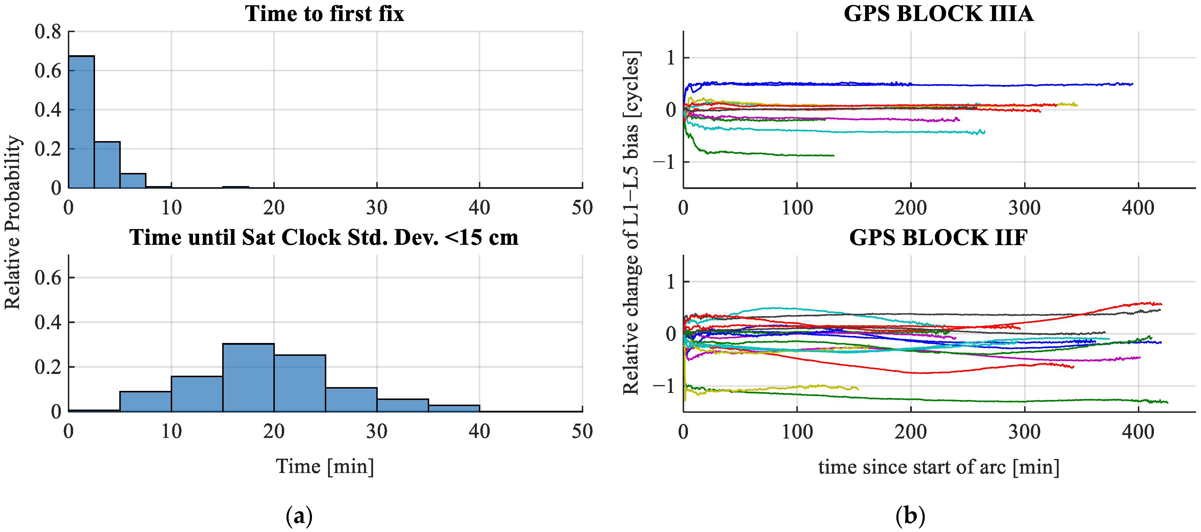
Of interest for a user of the PPP-RTK products provided by a regional network in real-time applications would be the time it takes for precise satellite clocks and biases to be available, since the rise of the satellite. In Figure 4a, two metrics are displayed: the time to first fix (TTFF) for an ambiguity-fixed solution for a satellite and the time until the standard deviation of the satellite clock falls below a certain threshold, here 15 cm. Computing a first fixed solution for a satellite can be done in under 10 min in almost all cases, whereas a satellite clock better than 15 cm is expected to be available in around 20 min. Providing satellite clocks and biases to the user that have not been estimated yet with high accuracy would not be a problem if the full VCM information of the network parameters were transmitted to the user as well. However, since satellite clocks and biases are usually treated as deterministic corrections on the user side, the VCM is discarded. Discarding the VCM of the network products leads to worse results for the user [33]. This effect, however, is less pronounced the smaller the uncertainty of the network parameters is. In this work, the threshold for a satellite to be considered for a user is 15 cm for the standard deviation of the satellite clock estimate. This has shown to be a good compromise regarding the time frame in which this satellite becomes available to the user and the effect of neglecting the VCM of the network products on the user solution.
As noted in the introduction, GPS L5 phase biases are estimated as random walk parameters with the random walk process noise of 1   c y c l e h , since significant variations of the L5 phase bias relative to the L1 and L2 phase biases have been demonstrated for GPS IIF satellites [11]. In Figure 4b, the differences between L1 and L5 phase biases are visualized for GPS BLOCK IIIA and GPS BLOCK IIF satellites. It can be seen that the differenced phase biases vary a lot more for BLOCK IIF satellites, whereas the differenced phase biases for BLOCK IIIA satellites appear to be almost constant. Note that time-varying GPS L5 phase biases have been assumed for BLOCK IIIA and BLOCK IIF to enable a fair comparison.

4.2. User Results

In this chapter, the satellite clocks and biases as generated by the network are used at the user level. The focus is put on analyzing the convergence time and accuracy of the user coordinate solution. Regarding the time stability of the user coordinates, two different assumptions are being made: user coordinates are assumed to be constant or epoch-wise parameters. When coordinates are assumed to be constant, this is referred to as the static coordinate solution. The case of epoch-wise parameters is referred to as the kinematic coordinate solution. The processing at the user level is done for multi-frequency observations in Section 4.2.1 and for dual frequency observations in Section 4.2.2 to assess the advantages of the multi-frequency approach regarding the convergence time of the coordinate solution.

4.2.1. Multi-Frequency

To evaluate the performance of the generated forward-filtered PPP-RTK network products, observations of multi-frequency and multi-GNSS receivers with known long-term reference positions are processed. To enable a fair comparison between the constant phase bias and the reference phase clock approach, the same observations are processed in both approaches. More specifically, only satellites are processed at epochs where their classic code satellite clock estimate has a standard deviation of 15 cm in the constant phase bias approach. In total, 17 receivers observing all GNSS listed in Table 1 have been processed, and 23 hourly static and kinematic coordinate solutions have been computed for every receiver. The first hour has been discarded, as the results in the first hour would be degraded by the fact that significantly fewer satellites would be available for the user, especially in the first 20 min. Out of all computed solutions, one has been discarded, as the computed coordinate solution had a significant offset to the reference solution, most likely caused by a faulty ambiguity resolution.
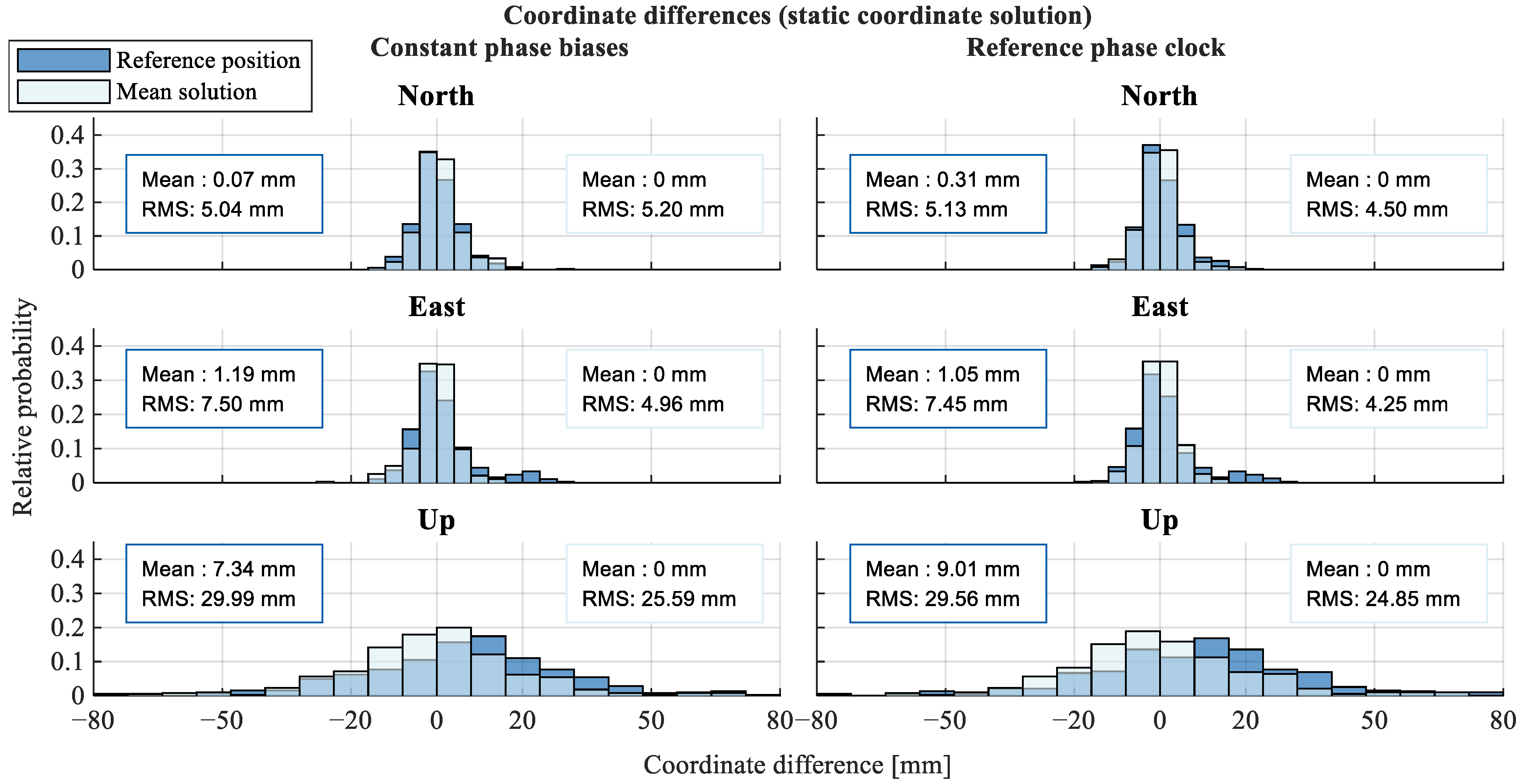
In Figure 5, the coordinate differences between the 1-hour static coordinate estimates and the long-term EUREF reference position and the mean position of all 23 hourly constant coordinate solutions are visualized. It can be seen that highly accurate static solutions can be computed in one hour, with the RMS of the horizontal components being around 5 mm and 7 mm for the north and east components, respectively, when compared to the reference and mean solutions. The RMS of the vertical offset is around three times larger than that of the horizontal offset and also has a significant bias of almost 1 cm when compared to the reference solution.
Comparing the two different approaches regarding the receiver and satellite phase biases, the differences in the horizontal components are negligible and below 1 mm in all cases. Introducing a reference phase clock has increased the mean difference to the reference solution by 2 mm, while the precision has improved by slightly below 1 mm. Considering the negligible differences the two approaches have on the static receiver coordinate solution, the following results are only presented for the constant phase bias approach in order to keep the presented results concise.
In Figure 6a, the temporal information of the generated static and kinematic solutions is visualized. It can be seen that even with no regional atmospheric corrections, fast ambiguity resolution is possible. For 77% of all solutions, ambiguity resolution was achieved in three epochs or fewer for both static and kinematic receiver coordinates. In 91% of all cases, a fixed solution could be computed after five epochs or fewer, and in 99% of solutions, in 20 epochs or fewer. The fastest TTFF is achieved in two epochs, which happened in 7% and 6% of all cases for the static and kinematic cases, respectively. It is important to note that this was achieved with an average of around 24 visible satellites. It was observed that some receivers had better performance regarding the quality of their solution and the TTFF. No significant differences in ambiguity resolution performance between static and kinematic receivers were observed; hence, the bar plots in Figure 6a mostly overlap.
Note that a fixed solution is only computed when at least five satellites are fixed, although in more than 97% of all cases, the first fixed solution was computed with at least 10 fixed satellites. A satellite is considered fixed when all ambiguities about it are resolved. In 92% of all cases, more than 80% of satellites have been fixed at the last epoch. A failure to fix all satellites at the last epoch could be due to some satellites not being observed long enough or cycle slips that have been previously introduced but not repaired yet, but it does not necessarily imply a failure of the satellite clocks and biases to enable ambiguity resolution at the user level.
Next, we take a closer look at the kinematic coordinate solutions. In Figure 6b, the temporal variation of the mean and the 0.95-quantile horizontal and vertical difference from the reference position are shown. After 1 min, the mean horizontal and vertical offsets are 3.9 cm and 11.0 cm, respectively, and after 2 min, they are 2.0 cm and 6.1 cm. The horizontal 0.95-quantile converges to an offset of around 2.5 cm after 3 min, while it takes around 6.5 min for the 0.95-quantile of the vertical offset to converge to around 7.5 cm.
At last, we take a closer look at the single epoch positioning performance and how it is affected by the fixing of the reparameterized wide-lane ambiguities. In Figure 7, the coordinate residuals correspond to the reference position at the first epoch of each hourly solution. The residuals are shown for the case that no wide-lane ambiguities are fixed to integers and for the case that wide-lane ambiguities are attempted to be fixed to integers. It can be seen that the reparameterization of the ambiguities and subsequent ambiguity resolution of the wide-lane ambiguities drastically improve the instantaneous positioning accuracy. The RMS of the north coordinate residuals improves from 29 cm to 10 cm, the RMS of the east residuals from 26 cm to 8 cm, and the RMS of the vertical residuals from 127 cm to 59 cm. The mean residuals improve slightly or remain comparable. The mean north residual is 1 cm in both cases, the mean east residual improves from −2 cm to −1 cm, and the mean vertical residual improves from 8 cm to 5 cm.

4.2.2. Dual-Frequency

In the previous chapter, the performance of multi-frequency and multi-GNSS PPP-RTK with no regional atmospheric corrections was accessed. Many other contributions, like those mentioned in the Introduction [3,4,6], are based on dual-frequency observations. Especially the common approach to PPP-RTK, where ionospheric-free code and phase observations are processed in combination with the Melbourne–Wübbena linear combination [34,35], which makes use of only dual-frequency observations. To gain further insight into the benefits of a multi-frequency approach over a dual-frequency approach, user processing is repeated and limited to two frequencies. In this chapter, we take a closer look at how dual-frequency affects the convergence time of the kinematic user coordinate solution when compared to a multi-frequency approach. For this, the static phase bias PPP-RTK products are used again to compute kinematic coordinate solutions with dual-frequency observations. The two frequencies used are the first two frequencies of each GNSS listed in Table 1.
In Figure 8, the performance of the presented methods is visualized for kinematic coordinate solutions. When compared to the results of the multi-frequency processing (see Figure 6), it is clear that the time until an accurate ambiguity-fixed solution is available significantly increases. While a fixed solution was achievable in three or fewer epochs in most cases with multi-frequency observations, this increased to seven or fewer epochs. Specifically, a fixed solution was achieved in seven epochs or fewer in 71% of all cases. In 10 and 20 epochs or less, a fixed solution was found in 94% and 97% of all cases, respectively.
With the presented methods of wide-lane ambiguity resolution, it was not possible in any case to fix the wide-lane ambiguities in the first epoch. The single epoch positioning results are thus not differentiated in Figure 9. This leads to worse single epoch positioning performance when compared to the wide-lane fixed multi-frequency counterpart. When compared to the no wide-lane fix multi-frequency results, the dual-frequency results are still worse. The rms of the single epoch’s north, east, and vertical residuals are given as 39 cm, 31 cm, and 156 cm, respectively.

5. Discussion and Outlook

The results show that an ambiguity-fixed precise coordinate solution with PPP-RTK without regional atmospheric corrections can be reduced to just a few epochs when multi-frequency multi-GNSS observations with a temporal resolution of 30 s are used in ideal conditions at the user level. When only dual-frequency observations are available, the single epoch positioning accuracy decreases significantly as a result of no wide-lane ambiguities qualifying for instantaneous ambiguity resolution. Furthermore, the minimum number of epochs required to achieve an ambiguity-fixed solution increases significantly when only dual-frequency observations are considered by the user. These results have been achieved with a regional network based in Europe, where only forward-filtered network products have been considered and no regional atmospheric corrections have been used. In theory, the results should be similar when global networks are considered. The reason is that satellite and station coordinates were fixed at the network level, so the only remaining parameter that is affected by the network geometry, i.e., the spatial distribution of the reference receivers, is the wet tropospheric zenith delay. The relevant network products for the user, i.e., satellite clocks and biases, are non-geometric parameters. In cases where the spatial distribution of reference receivers is not large enough, a rank deficiency between the wet tropospheric zenith delay and the satellite clock occurs, as described in [2]. This is, however, not applicable to the network considered here, as the spatial distribution is sufficient. As a consequence, the quality of the user solution and the time to fix it should not significantly depend on the distance of the user receiver from the reference stations, as long as it can be assumed that satellite clocks and biases estimated by the reference stations are available for the satellites observed by the user. This, of course, cannot be the case if the rover is too far away from the reference network and observes a different set of satellites. In this study, final satellite orbits are used that are generally only available for post-processing applications. In the event that PPP-RTK corrections were to be made available in real time, the repeatability of these results using predicted satellite orbits needs to be investigated further.
For 30 s observations, it was shown that ambiguity resolution can be achieved in just a few epochs in most cases. It needs to be further investigated how these findings translate to high-rate observations, as they are of higher relevance in kinematic applications. The methods presented here can also be used to process high-rate observations at the network and user levels. However, new problems may arise that were not present in 30 s observations. One issue that becomes more prevalent when high-rate observations are considered is the temporal correlation of especially code observations, as shown by, e.g., [36], where significant correlation for up to 10 s was observed for all signals. This could influence the validity of the stochastic assumptions that were made for the 30 s observations. Furthermore, it may be unrealistic to expect high-rate observations to be processed at the network level and the satellite clocks made available to the user at, e.g., each second. In cases where the observation sampling rate of the user receiver exceeds that of the reference network, one must think about extrapolating satellite clocks and how their quality decreases as time passes. The first part could be solved by adding a satellite clock drift to the state vector. The latter part needs to be investigated for different satellite clocks as the time stability between satellite clocks varies.
The estimation of all receiver and satellite phase biases as constants compared to introducing a reference phase clock has led to negligible differences in the estimation of the user point position. With the introduction of the GPS L5 satellite phase bias as a random walk parameter, a notable difference in the temporal variation between the L5 and L1 biases for GPS BLOCK IIIA and IIF satellites has been observed, in the sense that BLOCK IIF biases appeared to have a significantly higher temporal variation, confirming the findings in [11].
For real-time applications, where latency between the network products and the user solution is expected, modeling the uncertainty of network parameters over time becomes relevant. Especially the modeling of the VCM of the network products becomes increasingly relevant as latency increases, as shown in [33]. In this study, only satellites with a satellite clock estimate of a standard deviation of 15 cm or better were considered for the user processing since satellite clocks and biases were considered deterministic corrections. In cases where the VCM or an approximation thereof is used for the network parameters, this condition can be discarded. For a regional network, this would generally increase the number of available satellites for the user and eliminate or reduce the errors introduced by neglecting the VCM of the network parameters.
The functional model can be further improved by also using GLONASS satellites. Generally speaking, FDMA GLONASS satellites have a weaker functional model regarding the estimation of integer-valued ambiguities (see [5]), but nevertheless, a strengthening of the functional model is to be expected when more satellites are available. In addition to the GLONASS observations, the functional model can be further strengthened by introducing pseudo-observations in the form of ionospheric slant delays computed by regional network stations and interpolated to the user position like it was done, e.g., in [37,38]. Of further interest would be the density of reference stations required to compute the regional atmospheric corrections to significantly strengthen the functional model and possibly enable instantaneous or more reliable ambiguity resolution in combination with the methods used in this study. With these improvements in the functional model, the availability of a fixed solution in just a few epochs can hopefully be further increased.

Funding

The author acknowledges support by the Deutsche Forschungsgemeinschaft (DFG—German Research Foundation) and the Open Access Publishing Fund of Technical University of Darmstadt.

Data Availability Statement

EPN reference frame solution [15], CODE final orbits and ERP [16], Tropospheric modeling functions used in this study can be found at [39], GNSS-observations used are publicly available at: https://epncb.eu/ftp/obs/ (accessed on 15 February 2023), MLAMBDA functions used [24]. The results may be provided by the author at reasonable request.

Acknowledgments

The author acknowledges the European Permanent GNSS Network for making GNSS observation data and the reference frame realization available. Furthermore, the author acknowledges the Center for Orbit Determination in Europe (CODE) for providing the multi-GNSS satellite orbits used in this work.

Conflicts of Interest

The author declares no conflict of interest.

References

  1. Teunissen, P.J.G.; Khodabandeh, A. Review and principles of PPP-RTK methods. J. Geod. 2015, 89, 217–240. [Google Scholar] [CrossRef]
  2. Odijk, D.; Zhang, B.; Khodabandeh, A.; Odolinski, R.; Teunissen, P. On the estimability of parameters in undifferenced, uncombined GNSS network and PPP-RTK user models by means of S-system theory. J. Geod. 2015, 90, 15–44. [Google Scholar] [CrossRef]
  3. Geng, J.; Teferle, F.N.; Meng, X.; Dodson, A.H. Towards PPP-RTK: Ambiguity resolution in real-time precise point positioning. Adv. Space Res. 2011, 47, 1664–1673. [Google Scholar] [CrossRef]
  4. Li, P.; Zhang, X. Integrating GPS and GLONASS to accelerate convergence and initialization times of precise point positioning. GPS Solut. 2014, 18, 461–471. [Google Scholar] [CrossRef]
  5. Teunissen, P.J.G. A new GLONASS FDMA model. GPS Solut. 2019, 23, 100. [Google Scholar] [CrossRef]
  6. Brack, A.; Männel, B.; Schuh, H. GLONASS FDMA data for RTK positioning: A five-system analysis. GPS Solut. 2020, 25, 9. [Google Scholar] [CrossRef]
  7. Collins, P.; Bisnath, S.; Lahaye, F.; Héroux, P. Undifferenced GPS Ambiguity Resolution Using the Decoupled Clock Model and Ambiguity Datum Fixing. Navigation 2010, 57, 123–135. [Google Scholar] [CrossRef]
  8. Ge, M.; Gendt, G.; Rothacher, M.; Shi, C.; Liu, J. Resolution of GPS carrier-phase ambiguities in Precise Point Positioning (PPP) with daily observations. J. Geod. 2008, 82, 389–399. [Google Scholar] [CrossRef]
  9. Geng, J.; Shi, C.; Ge, M.; Dodson, A.H.; Lou, Y.; Zhao, Q.; Liu, J. Improving the estimation of fractional-cycle biases for ambiguity resolution in precise point positioning. J. Geod. 2011, 86, 579–589. [Google Scholar] [CrossRef]
  10. Geng, J.; Chen, X.; Pan, Y.; Zhao, Q. A modified phase clock/bias model to improve PPP ambiguity resolution at Wuhan University. J. Geod. 2019, 93, 2053–2067. [Google Scholar] [CrossRef]
  11. Montenbruck, O.; Hugentobler, U.; Dach, R.; Steigenberger, P.; Hauschild, A. Apparent clock variations of the Block IIF-1 (SVN62) GPS satellite. GPS Solut. 2012, 16, 303–313. [Google Scholar] [CrossRef]
  12. Yue, C.; Dang, Y.; Xue, S.; Wang, H.; Gu, S.; Xu, C. A Short-Term Forecasting Method of Inter-Frequency Clock Bias for GPS Block IIF Satellites. Remote Sens. 2022, 14, 4130. [Google Scholar] [CrossRef]
  13. Teunissen, P.J.G.; Verhagen, S. On the Foundation of the Popular Ratio Test for GNSS Ambiguity Resolution. In Proceedings of the 17th International Technical Meeting of the Satellite Division of The Institute of Navigation (ION GNSS 2004), Long Beach, CA, USA, 21–24 September 2004; pp. 2529–2540. Available online: http://www.ion.org/publications/abstract.cfm?jp=p&articleID=5937 (accessed on 20 March 2023).
  14. Bruyninx, C.; Legrand, J.; Fabian, A.; Pottiaux, E. GNSS metadata and data validation in the EUREF Permanent Network. GPS Solut. 2019, 23, 106. [Google Scholar] [CrossRef]
  15. Legrand, J. EPN Multi-Year Position and Velocity Solution C2220; Royal Observatory of Belgium: Uccle, Belgium, 2022. [Google Scholar] [CrossRef]
  16. Dach, R.; Schaer, S.; Arnold, D.; Prange, L.; Susnik, A.; Villiger, A.; Jäggi, A.; Villiger, A. CODE Final Product Series for the IGS [Datensatz]; Astronomical Institute, University of Bern: Bern, Switzerland, 2020; Available online: http://www.aiub.unibe.ch/download/CODE (accessed on 14 March 2023).
  17. Hofmann-Wellenhof, B.; Lichtenegger, H.; Wasle, E. GNSS—Global Navigation Satellite Systems: GPS, GLONASS, Galileo, and More; Springer Science & Business Media: Boston, NY, USA, 2007. [Google Scholar]
  18. Kouba, J.; Lahaye, F.; Tétreault, P. Precise Point Positioning. In Springer Handbook of Global Navigation Satellite Systems; Teunissen, P.J.G., Montenbruck, O., Eds.; Springer International Publishing: Cham, Switzerland, 2017; pp. 723–751. [Google Scholar] [CrossRef]
  19. Teunissen, P. Zero Order Design: Generalized Inverses, Adjustment, the Datum Problem and S-Transformations. In Optimization and Design of Geodetic Networks; Grafarend, E.W., Sansò, F., Eds.; Springer: Berlin/Heidelberg, Germany, 1985; pp. 11–55. [Google Scholar] [CrossRef]
  20. Wilson, R.J. Introduction to Graph Theory; Longman: London, UK, 2010. [Google Scholar]
  21. Khodabandeh, A.; Teunissen, P.J.G. Integer estimability in GNSS networks. J. Geod. 2019, 93, 1805–1819. [Google Scholar] [CrossRef]
  22. Teunissen, P. The invertible GPS ambiguity transformations. Manuscr. Geod. 1995, 20, 489–497. [Google Scholar]
  23. Chang, X.-W.; Yang, X.; Zhou, T. MLAMBDA: A modified LAMBDA method for integer least-squares estimation. J. Geod. 2005, 79, 552–565. [Google Scholar] [CrossRef]
  24. Verhagen, S.; Li, B. LAMBDA Software Package: Matlab Implementation, Version 3.0; Delft University of Technology and Curtin University: Perth, Austraila, 2012. [Google Scholar]
  25. Cocard, M.; Bourgon, S.; Kamali, O.; Collins, P. A systematic investigation of optimal carrier-phase combinations for modernized triple-frequency GPS. J. Geod. 2008, 82, 555–564. [Google Scholar] [CrossRef]
  26. Petit, G.; Luzum, B. (Eds.) IERS Technical Note, 36. In IERS Conventions (2010); Verlag des Bundesamts für Kartographie und Geodäsie: Frankfurt am Main, Germany, 2010. [Google Scholar]
  27. Le Provost, C.; Lyard, F.; Molines, J.M.; Genco, M.L.; Rabilloud, F. A hydrodynamic ocean tide model improved by assimilating a satellite altimeter-derived data set. J. Geophys. Res. Ocean. 1998, 103, 5513–5529. [Google Scholar] [CrossRef]
  28. Antenna. International GNSS Service. Available online: https://igs.org/wg/antenna/ (accessed on 20 March 2023).
  29. Wu, J.T.; Wu, S.C.; Hajj, G.A.; Bertiger, W.I.; Lichten, S.M. Effects of antenna orientation on GPS carrier phase. Manuscr. Geod. 1993, 18, 91–98. [Google Scholar]
  30. Landskron, D.; Böhm, J. VMF3/GPT3: Refined discrete and empirical troposphere mapping functions. J. Geod. 2018, 92, 349–360. [Google Scholar] [CrossRef]
  31. Montenbruck, O.; Schmid, R.; Mercier, F.; Steigenberger, P.; Noll, C.; Fatkulin, R.; Kogure, S.; Ganeshan, A.S. GNSS satellite geometry and attitude models. Adv. Space Res. 2015, 56, 1015–1029. [Google Scholar] [CrossRef]
  32. Luo, X.; Mayer, M.; Heck, B.; Awange, J. A Realistic and Easy-to-Implement Weighting Model for GPS Phase Observations. IEEE Trans. Geosci. Remote Sens. 2014, 52, 6110–6118. [Google Scholar] [CrossRef]
  33. Psychas, D.; Khodabandeh, A.; Teunissen, P.J.G. Impact and mitigation of neglecting PPP-RTK correctional uncertainty. GPS Solut. 2021, 26, 33. [Google Scholar] [CrossRef]
  34. Melbourne, W. The case for ranging in GPS-based geodetic systems. In Proceedings of the 1st International Symposium on Precise Positioning with the Global Positioning System, Rockville, MD, USA, 15–19 April 1985; pp. 373–386. [Google Scholar]
  35. Wübbena, G. Software Developments for Geodetic Positioning with GPS Using TI 4100 Code and Carrier Measurements. In Proceedings of the 1st International Symposium on Precise Positioning with the Global Positioning System, Rockville, MD, USA, 15–19 April 1985; U.S. Department of Commerce: Washington, DC, USA, 1985; pp. 403–412. Available online: https://cir.nii.ac.jp/crid/1571698599798417280 (accessed on 20 January 2023).
  36. Prochniewicz, D.; Wezka, K.; Kozuchowska, J. Empirical Stochastic Model of Multi-GNSS Measurements. Sensors 2021, 21, 13. [Google Scholar] [CrossRef]
  37. Wang, A.; Zhang, Y.; Chen, J.; Wang, H. Improving the (re-)convergence of multi-GNSS real-time precise point positioning through regional between-satellite single-differenced ionospheric augmentation. GPS Solut. 2022, 26, 39. [Google Scholar] [CrossRef]
  38. Li, X.; Huang, J.; Li, X.; Lyu, H.; Wang, B.; Xiong, Y.; Xie, W. Multi-constellation GNSS PPP instantaneous ambiguity resolution with precise atmospheric corrections augmentation. GPS Solut. 2021, 25, 107. [Google Scholar] [CrossRef]
  39. Re3data.Org. VMF Data Server. 2016. Available online: https://vmf.geo.tuwien.ac.at/ (accessed on 15 November 2022). [CrossRef]
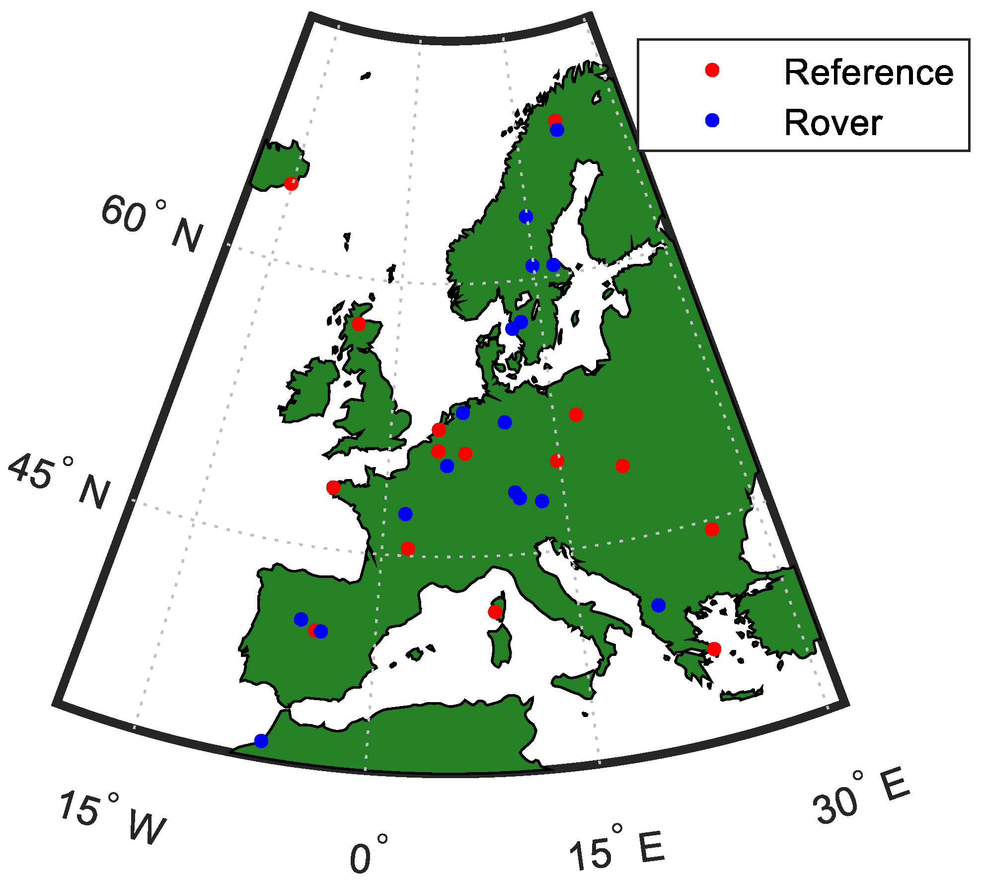
Figure 1. Map of reference stations used. Station identifiers of the network: AJAC, BOR1, BRST, BRUX, BUCU, CEBR, DLF1, DYNG, EGLT, EUSK, GANP, GOPE, HOFN, INVR, KIRU; and the rover: AUBG, KIRU, LEK6, MAR7, OBE4, ONSA, ORID, OST6, PTBB, RABT, REDU, SALA, SBG2, SPT0, VFCH, VILL, WSRT.
Remotesensing 15 02792 g001
Figure 2. Connectivity in GNSS Networks: (a) For the third satellite from the left, observations on two frequencies (“freq”) do not exist (or one code and phase observation). As a result, the ionospheric slant delay cannot be separated from the satellite clock (when no temporal constraints are imposed), and observations from this satellite are rank-deficient with the CC-model. (b) A connected graph and its ST. If this is the graph of a specific phase signal, e.g., GPS L5, then the ambiguities belonging to the ST could be used as an S-basis restriction, and the remaining ambiguities would be integer estimable.
Remotesensing 15 02792 g002
Figure 3. Processing scheme for network and user.
Remotesensing 15 02792 g003
Figure 4. For brevity, only the results of constant phase bias estimation are shown. Other results do not differ significantly. (a) TTFF for network receivers and time until the satellite clock standard deviation falls below 15 cm. Note that satellites are only considered for the user when the clock estimate standard deviation is below that threshold. (b) Between L1 and L5 satellite phase biases for GPS satellites BLOCK IIF and IIIA differed from their starting epoch. Greater variation is apparent for GPS BLOCK IIF satellites, plausibly explaining the need to model the L5 satellite phase bias as a random walk parameter only for GPS BLOCK IIF. Each line represents a satellite arc. Only satellite arcs that have been observed for more than 50 epochs are shown.
Remotesensing 15 02792 g004
Figure 5. One-hour static coordinate solution north, east, and up differences to the reference and mean solutions, further comparing the differences between constant phase biases and a phase reference clock.
Remotesensing 15 02792 g005
Figure 6. Visualizing the temporal characteristics of the user solution. Kinematic processing refers to the epoch-wise estimation of user coordinates, using static coordinates as constant parameters. Processing is done with the constant phase bias assumption. Note that the temporal resolution of the observations used is 30 s. (a) Epochs to first fix (ETTF) for kinematic and static processing and the number of satellites observed and fixing rate (ratio of fixed to observed satellites) at the last epoch. (b) Horizontal and vertical distances of estimated receiver coordinates (kinematic) to the reference position.
Remotesensing 15 02792 g006
Figure 7. Single epoch positioning performance for multi-GNSS observations. Reparameterized ambiguities can be fixed to integers in just one epoch, improving the performance significantly.
Remotesensing 15 02792 g007
Figure 8. Visualizing the temporal characteristics of the user solution. Similar to Figure 6, except that the results for dual-frequency processing are shown.
Remotesensing 15 02792 g008
Figure 9. Single epoch positioning performance for dual-frequency observations. Reparameterized ambiguities could not be fixed with the introduced methods in a single epoch.
Remotesensing 15 02792 g009
Table 1. GNSS and signals considered. Note that the signal name follows the RINEX 3 conventions. The * is a wildcard for C (= code) or L (= phase).
GNSSReceiver Type AReceiver Type B
GPS*1C, *2W, *5Q*1C, *2W, *5X
Galileo*1Q, *5Q, *6C, *7Q, *8Q*1X, *5X, *6X, *7X, *8X
BDS*2I, *6I, *1P, *5P*2I, *6I, *1X, *5X
Table 2. Parameter S-basis restriction implicitly applied in Equation (2). The restricted parameters or the specified combination are set to 0 to eliminate rank deficiencies.
S-Basis RestrictionParameterCondition
CC-R S-basis
Pivot Receiver Clock d t r r = 1
Pivot Receiver Code, Phase Biases d r , j A , δ r , j A r = 1
Receiver IF Code Bias d r , I F A r > 1 , A = 1
Receiver GF Code Bias d r , G F A r > 1
Satellite IF Code Bias d I F s , A For signals exclusive to receiver Type A
Satellite GF Code Bias d G F s , A For signals exclusive to receiver Type A
Pivot Receiver Ambiguities * N r , j s , A r = 1
Pivot Satellite Ambiguities * N r , j s , A r > 1 , s = 1
CC-R S-basis Adaptations
Pivot Satellite Code Bias d j s , A s = 1 (For satellite code biases not observed by pivot receiver)
Satellite GF Code Bias d G F s , A s 1 (For GNSS A where no common signal between Receiver Type A and B exists)
IF Code Bias d r , I F = 1 μ 2 μ 1 μ 2 d r , 1 μ 1 d r , 2 , d I F s = 1 μ 2 μ 1 μ 2 d 1 s μ 1 d 2 s . GF Code Bias d r , G F = 1 μ 2 μ 1 d r , 2 d r , 1 , d G F s = 1 μ 2 μ 1 d 2 s d 1 s . * In practice, this is done with the more flexible Spanning Tree approach, as described later in Section 3.1.
Disclaimer/Publisher’s Note: The statements, opinions and data contained in all publications are solely those of the individual author(s) and contributor(s) and not of MDPI and/or the editor(s). MDPI and/or the editor(s) disclaim responsibility for any injury to people or property resulting from any ideas, methods, instructions or products referred to in the content.