Simulation Analysis of the Geometric Positioning Accuracy for MEO- and HEO-SAR Satellites
Abstract
1. Introduction
2. Material and Methods
2.1. Basic Principles
2.2. Construction of the Simulation Geometric Model
2.2.1. Real Geometric Model Construction
2.2.2. Virtual Simulation Geometric Model Construction
2.2.3. Evaluation Method for Geometric Positioning Accuracy with GCPs
2.3. Simulation Processing Flow
2.3.1. Simulation without GCPs
- (1)
- SAR satellite orbit simulation. The SAR satellite orbit simulation using STK software was achieved as described in the following steps:
- (1.1)
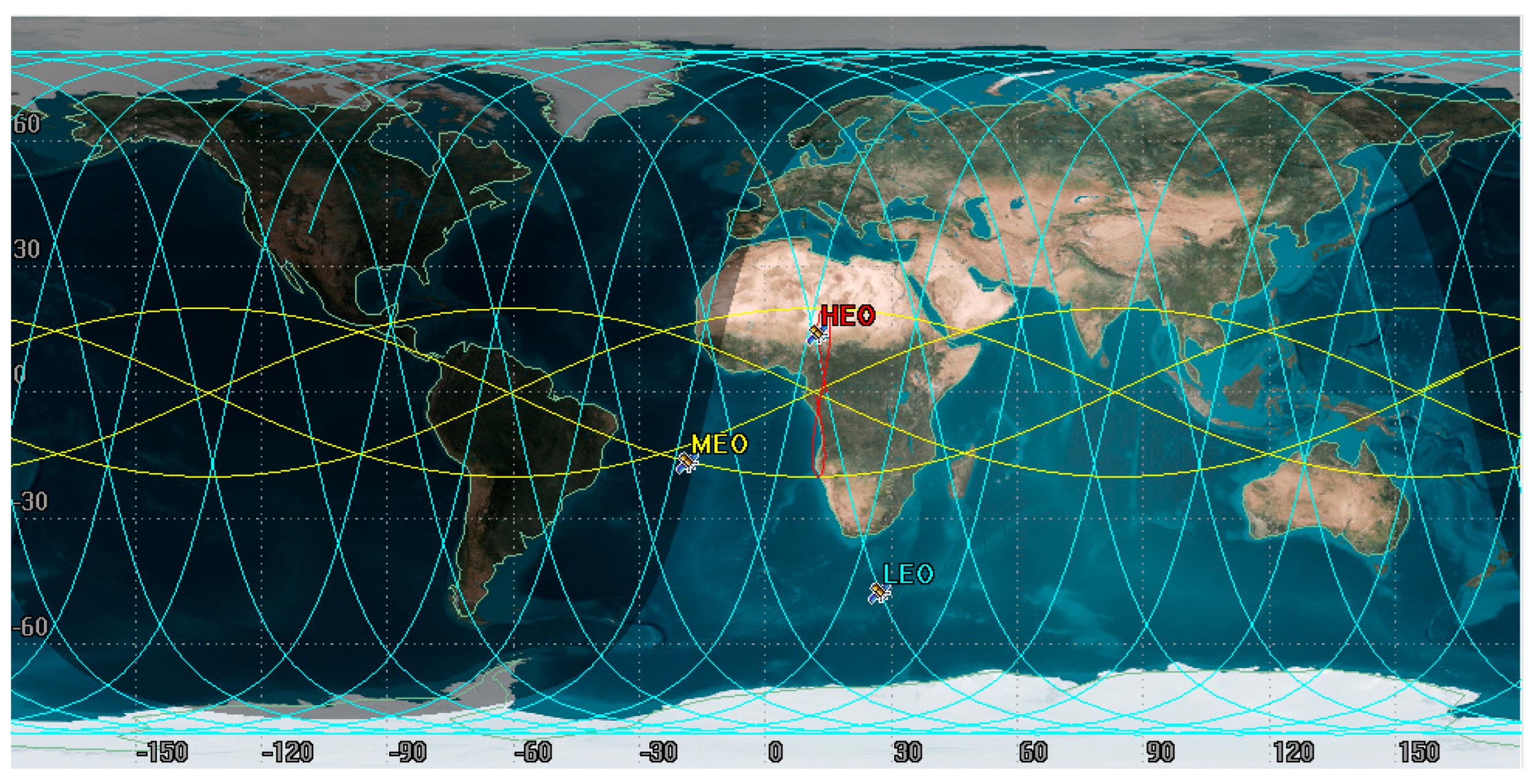
- Satellite orbit parameter settings: these include the SAR satellite orbit semi-major axis, orbit eccentricity, orbit inclination parameter, right ascension of the ascending node (RAAN), orbit altitude, satellite orbit type and simulation start and end times.
- (1.2)
- Sensor parameter setting: the sensor was added to the setup satellite object and the sensor parameters were set by defining the property option attributes.
- (1.3)
- Satellite position and velocity generation: once the sensor parameters have been set successfully, the satellite position and velocity can be obtained by selecting the position velocity from the Reports and Graph Manager option.
- (2)
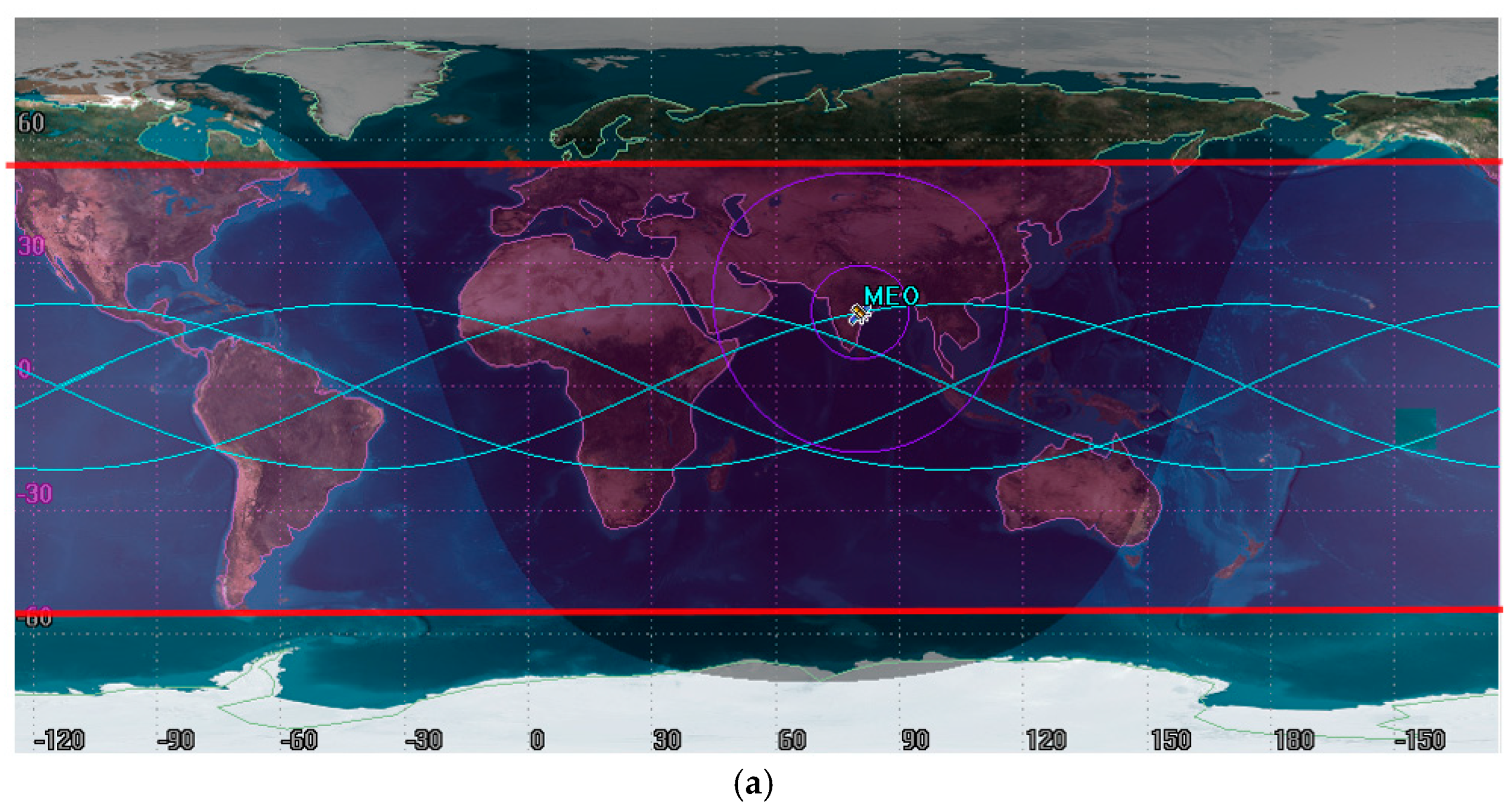
- Image area prediction. Using the simulated MEO- and HEO-SAR orbit parameters, the range of the radar beam covering the Earth’s surface can be predicted according to the satellite’s instantaneous position (including sub-satellite point coordinates and height) and viewing angle. The steps to achieve imaging area prediction mainly include grid settings, coverage resources, coverage analysis time period setting, figure-of-merit (FOM) type selection and display and coverage area generation.
- (2.1)
- Grid settings: to define the coverage area, a coverage definition object to the scene in step (1) was added and the grid coverage used to define the coverage area boundaries was selected.
- (2.2)
- Coverage resources: allows the selection of STK objects as coverage resources. The pre-built sensors to be assigned.
- (2.3)
- Coverage analysis time period setting: we selected the coverage analysis period and then the “Calculate Computer Access” option to calculate coverage.
- (2.4)
- FOM type selection and display: to simulate the imaging areas of the MEO- and HEO-SAR satellites, two types of objects were provided by STK: coverage definition and FOM. An FOM object on the coverage definition object was created, the FOM type was set as the access duration option, and the minimum value for the calculation criteria was selected. Then the satisfaction field on the definition page in the satisfaction pane was selected, and at least one option for the gate value for satisfaction was selected.
- (2.5)
- Generation of the coverage area: the extent of the generated area was visualized by selecting the “Show contour” function.
- (3)
- Simulation of realistic satellite-to-ground geometric imaging relationships. Based on the position and velocity information of the MEO- and HEO-SAR satellites obtained in step (1) and the imaging area predicted in step (2), the real slant range and Doppler center frequency values at the imaging moment were calculated using the Bigemap GIS Office to select the coordinates of the ground point in the visible area using the real geometric model, as shown in Equation (5).
- (4)
- Virtual imaging geometry relationship simulation. The virtual simulation geometry model with errors (Equation (6)) allows the analysis of both the effect of a single error source on the geometric positioning accuracy and the effect of multiple combined error sources on the geometric positioning accuracy.
- (5)
- Three-dimensional geographic coordinates without GCPs. Based on the orbital parameters of the MEO- and HEO-SAR satellites obtained from the simulation in step (1) and the virtual simulation geometry model constructed in step (4), the three-dimensional geographic coordinates of the GCP were obtained.
- (6)
- Error statistics. The three-dimensional geographic coordinates calculated in step (5) were subjected to residual calculation with real three-dimensional geographic coordinates, after which the RMS error of the residuals of the ground points was counted.
2.3.2. Simulation with GCPs
- (1)
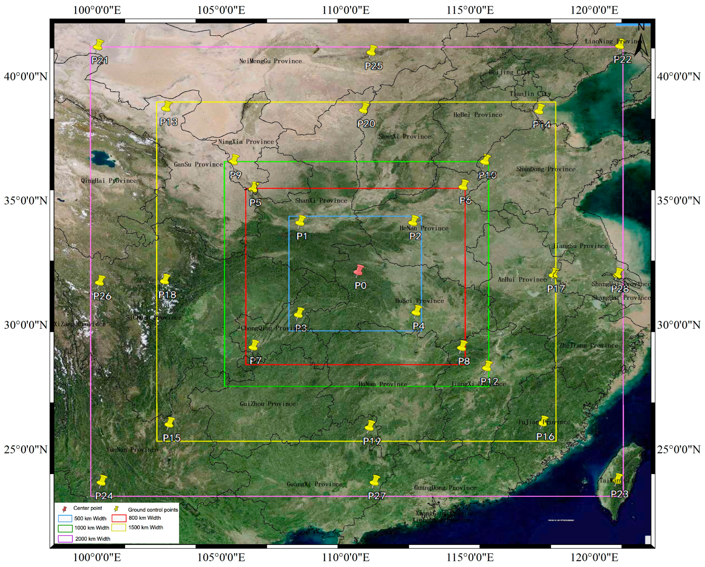
- Three-dimensional geographic coordinates with GCPs. In the positioning calculation without GCPs, only one ground point was simulated. However, the positioning calculation with GCPs required multiple points to be uniformly selected in the simulation area. Based on the orbital parameters of the MEO- and HEO-SAR satellites obtained from the simulation and the virtual simulation geometry model constructed, the three-dimensional geographical coordinates of the GCPs were solved.
- (2)
- Error statistics. The residual calculation between the three-dimensional geographic coordinates calculated in step (1) and the real three-dimensional geographic coordinates. The mean value of the positioning error was then calculated, along with the residual of the positioning error and the mean value of each ground point. Finally, the RMS error of the residuals of the ground points was calculated to obtain the geometric positioning accuracy with the GCPs.
3. Experiments and Analysis
3.1. Simulation Data
3.1.1. Orbital Data Simulation
3.1.2. Coverage Analysis
3.1.3. Selection of Simulation Error
3.2. Results and Analysis
- (1)
- Method validation. The geometric positioning accuracy of the LEO-SAR satellite was simulated using the relevant parameters. The effectiveness of the method was verified by comparing it with the measured geometric positioning accuracy of the SAR satellite in orbit.
- (2)
- Geometric positioning accuracy without GCP simulation. In the simulation imaging area, a GCP was selected. The simulation method proposed in this study was used to simulate the geometric positioning accuracy without GCP. The effects of single and multiple error sources and different satellite orbital positions on the geometric positioning performance of the satellite were analyzed.
- (3)
- Simulation experiment of the geometric positioning accuracy with GCPs. Several GCPs were evenly selected in the simulation imaging area, and the geometric positioning accuracy with GCPs was calculated separately using the simulation method proposed in this study. The geometric positioning accuracy with GCPs was statistically analyzed. A comparative analysis of the geometric positioning accuracy at different imaging widths and orbital positions was performed.
3.2.1. Method Validation Experiments
- (1)
- Geometric positioning accuracy of LEO-SAR satellites without error
- (2)
- Geometric positioning accuracy of LEO-SAR satellites with errors
3.2.2. Simulation Analysis of Geometric Positioning Accuracy without GCPs
- (1)
- Influence of a single error source on the geometric positioning accuracy of MEO- and HEO-SAR satellites
- (2)
- Combined effects of multiple error sources on geometric positioning accuracy of MEO- and HEO-SAR satellites
- (3)
- Influence of different orbital positions on the geometric positioning accuracy
- (4)
- Influence of different period positions of HEO-SAR satellites on geometric positioning accuracy
3.2.3. Simulation Analysis of Geometric Positioning Accuracy with GCPs
4. Discussion
4.1. Validity of the Simulation Method
4.2. Geometric Positioning Accuracy Characteristics of MEO-SAR Satellite
- (1)
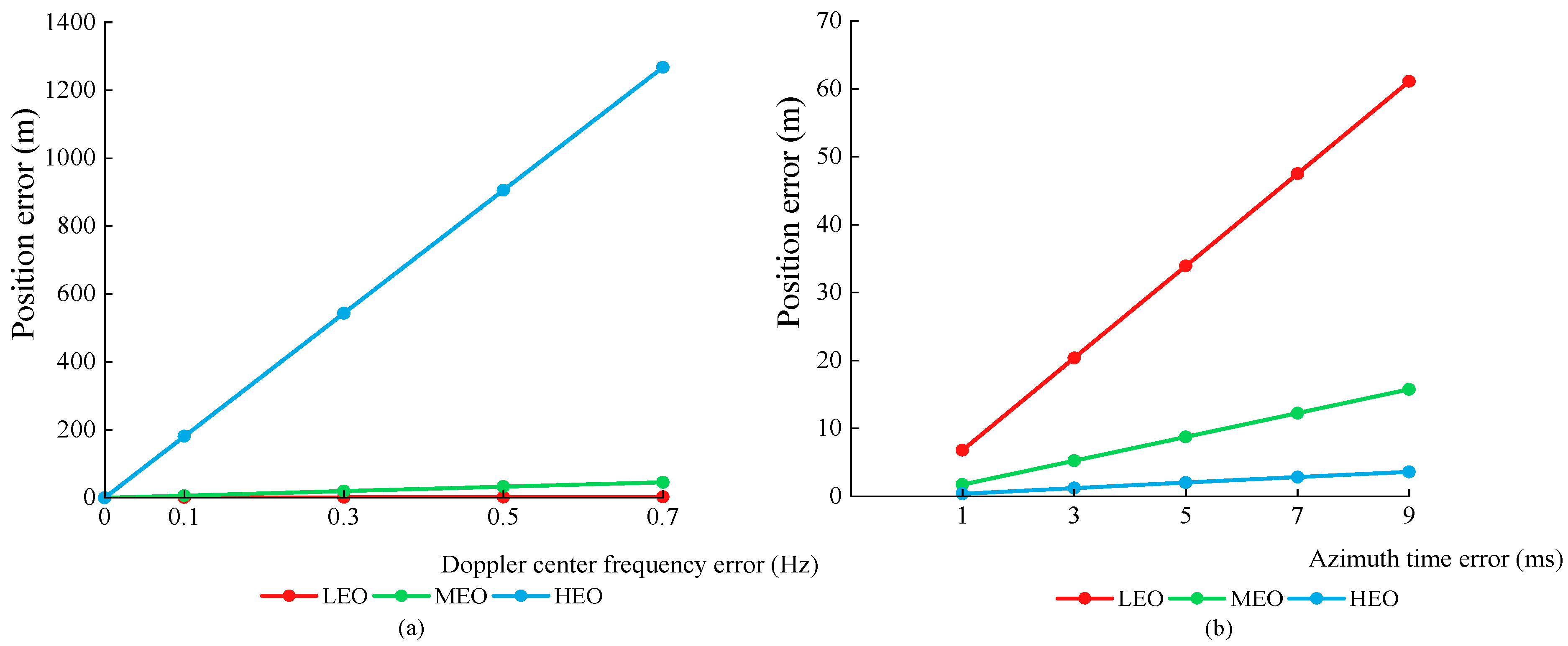
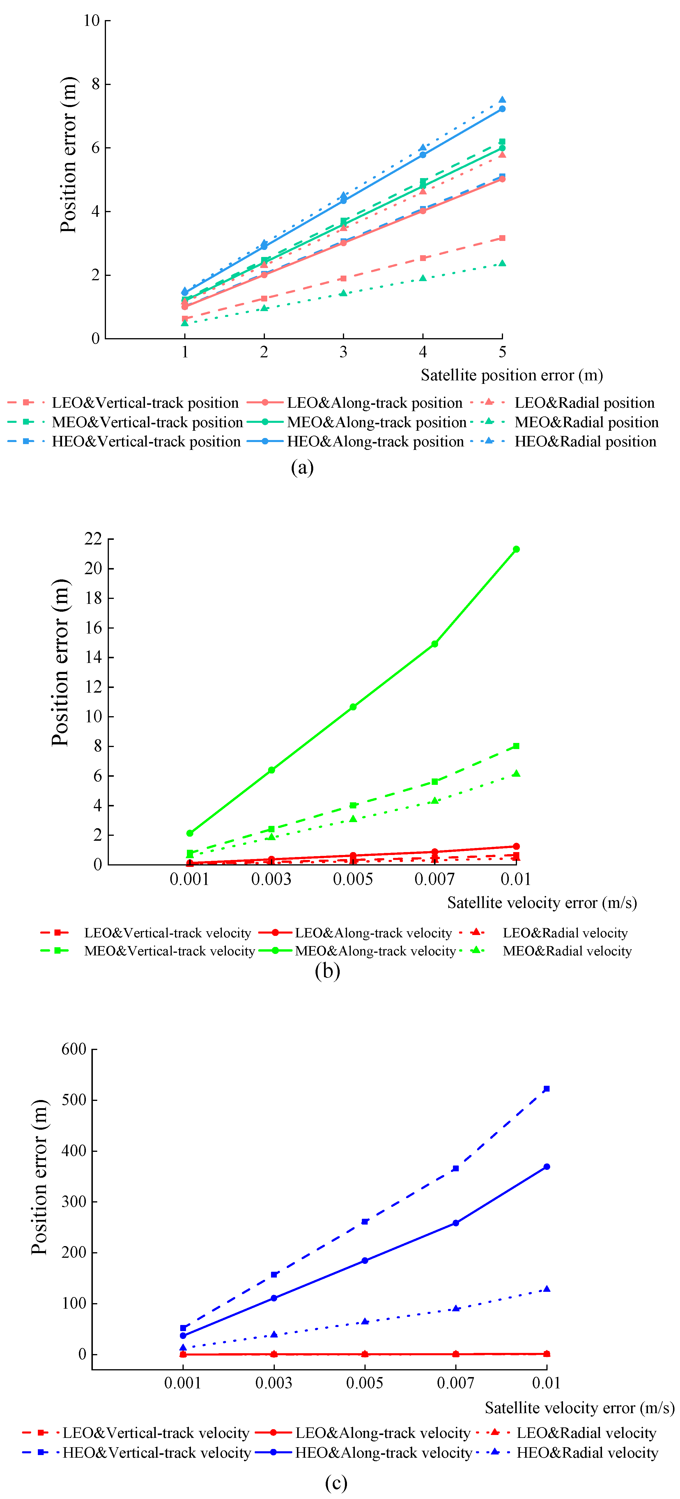
- According to the experimental results in Section 3.2.2, geometric positioning accuracy decreased as the incidence angle increased. In the case of combined errors, as shown in Table 3, all error sources to be analyzed were divided into five groups. It can be seen from Figure 10 that the combination of errors increased the corresponding interference value and the MEO-SAR satellite geometric positioning accuracy decreased by approximately 33 m between each group.
- (2)
- In the simulation experiments of geometric positioning accuracy without GCPs, when the combined error was small, the incidence angle had a greater impact on the MEO-SAR satellite. According to the experimental results in Section 3.2.2, the geometric positioning error of the MEO-SAR satellite was approximately 24–48 m at different orbital positions. Positioning accuracy can be improved by numerical control of the angle of incidence and elevation errors.
- (3)
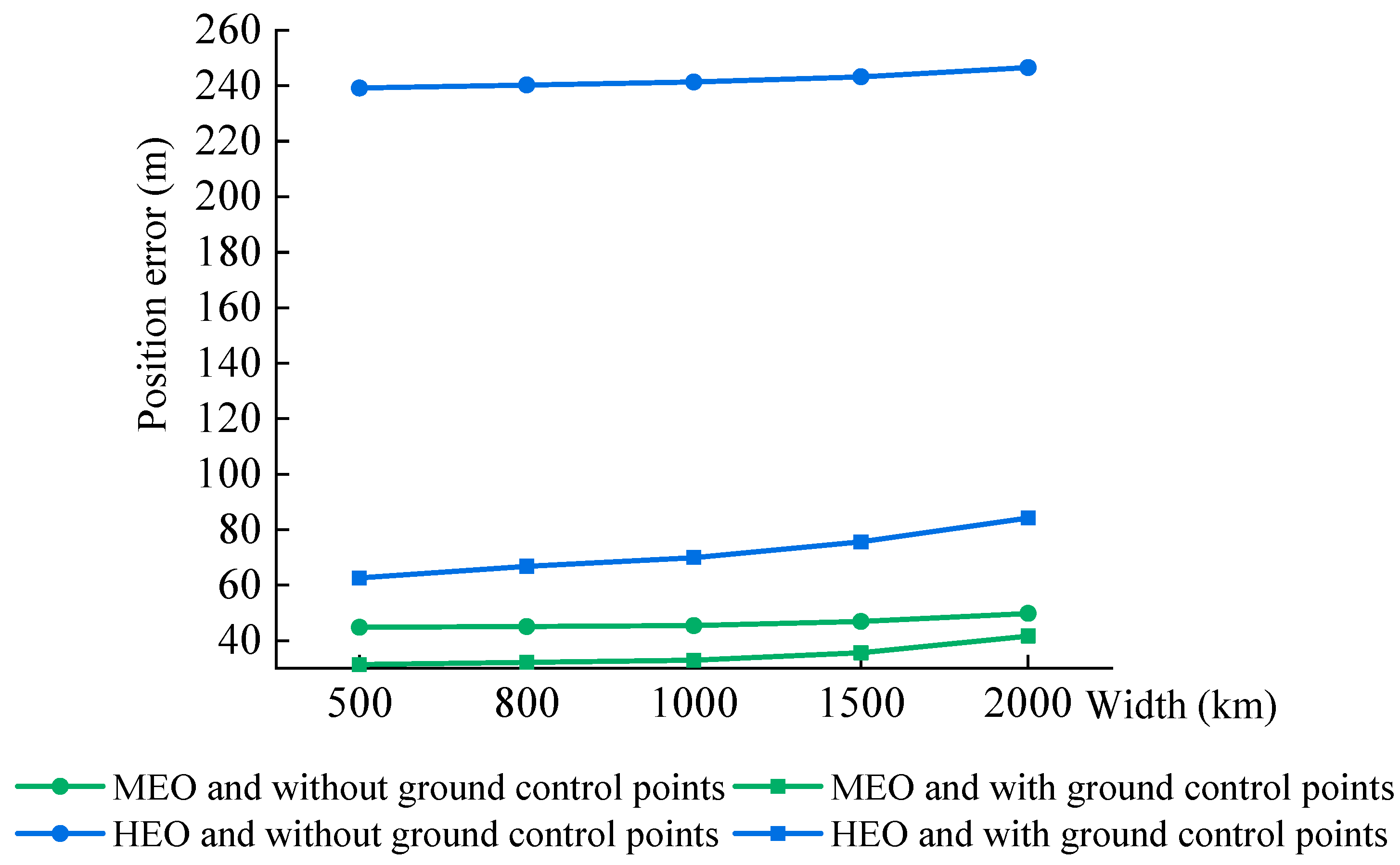
- When the simulation experiment of geometric positioning accuracy with GCPs was conducted, part of the systematic errors could be effectively eliminated, and the geometric positioning accuracy of the MEO-SAR satellite was improved. According to the comparative analysis of the experimental results in Section 3.2.3, in the case of combined errors, the geometric positioning error without GCPs of the MEO-SAR satellite was ~44–49 m, whereas the geometric positioning error with GCPs was ~31–41 m.
4.3. Geometric Positioning Accuracy Characteristics of HEO-SAR Satellite
- (1)
- From Section 3.2.2, it can be seen that among the experimental results of a single error source, the Doppler center frequency error and satellite velocity error had relatively greater negative impacts on the geometric positioning accuracy of the HEO-SAR satellite. It can be seen from Figure 9 that for each 0.1 Hz increase in the Doppler center frequency error, the HEO-SAR satellite positioning error increased by ~182 m. Additionally, Figure 10c shows that for each 0.002 m/s increase in the vertical-track velocity error and radial velocity error, the HEO-SAR satellite positioning error increased by approximately 104 m and 110 m, respectively.
- (2)
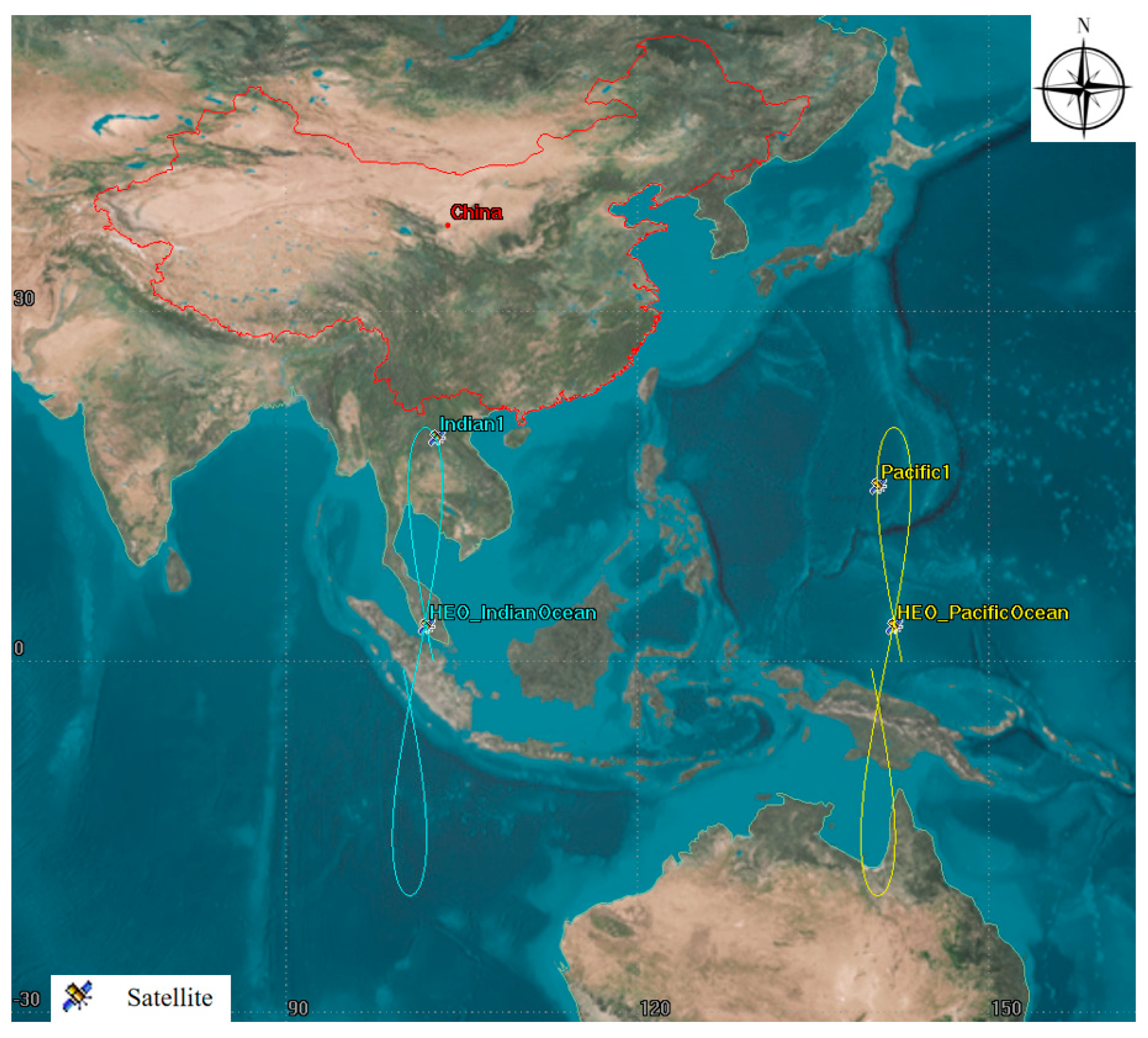
- In the simulation experiments of the geometric positioning accuracy without GCPs, we observed that the intersection point of the figure-of-eight shape could be selected for the geometric positioning accuracy calculation of the HEO-SAR satellite, while the inflection point of the figure-of-eight shape was not suitable for the same. According to the results described in Section 3.2.2, the geometric positioning accuracy calculation results of the HEO-SAR satellite at the intersection of the figure-of-eight track are better than those at the figure-of-eight inflection point, as the latter are not suitable for geometric positioning accuracy calculations at different orbital positions.
- (3)
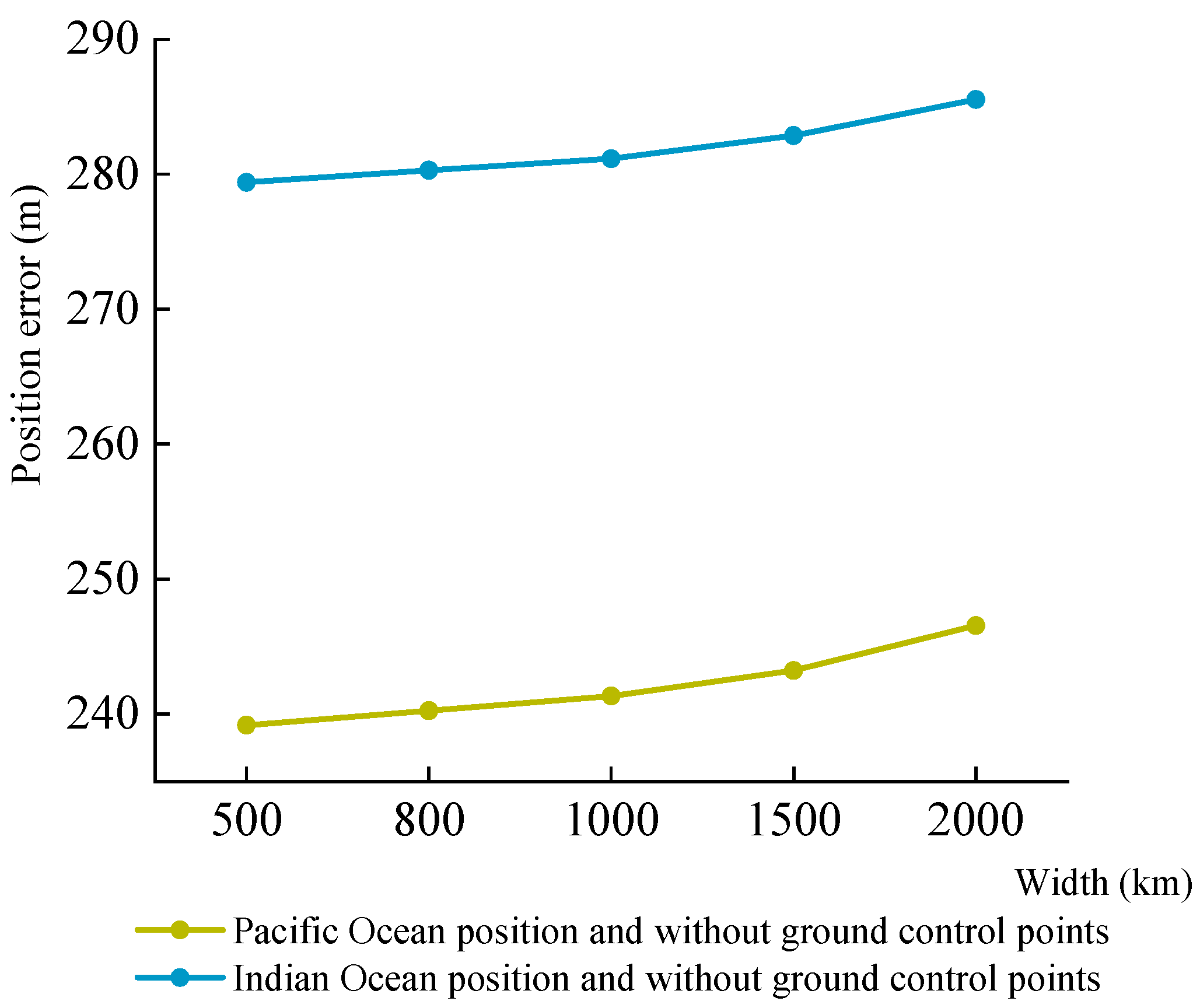
- When the simulation experiment of geometric positioning accuracy with GCPs was carried out, the geometric positioning accuracy of the HEO-SAR satellite was improved. According to the comparative analysis of the experimental results in Section 3.2.3, under the influence of multiple error sources, the geometric positioning error without GCPs of the HEO-SAR satellite was ~239–246 m, whereas the geometric positioning error with GCPs was ~62–84 m.
5. Conclusions
- (1)
- In this paper, the corresponding error and simulated LEO-SAR satellite parameters are used for experimental verification. The simulated LEO SAR satellite geometric positioning accuracy reaches 2.43 m. The positioning accuracy of the GF-3 satellite simulated in literature 19 is 2.56 m. Comparing the positioning data of the LEO-SAR satellite and the GF-3, it can be seen that the method proposed in this paper is effective.
- (2)
- In the geometric positioning accuracy analysis of MEO-SAR satellites, the position of the side-looking mode with a large incidence angle should be selected.
- (3)
- In the geometric positioning accuracy analysis of HEO-SAR satellites, the Doppler center frequency error and satellite velocity error should be limited.
Author Contributions
Funding
Data Availability Statement
Acknowledgments
Conflicts of Interest
References
- Buckreuss, S.; Werninghaus, R.; Pitz, W. The German satellite mission terraSAR-X. In Proceedings of the IEEE Radar Conference, Rome, Italy, 26–30 May 2008; pp. 1–5. [Google Scholar]
- Li, T.; Fan, J.; Liu, Y.; Lu, R.; Hou, Y.; Lu, J. An Improved Independent Parameter Decomposition Method for Gaofen-3 Surveying and Mapping Calibration. Remote Sens. 2022, 14, 3089. [Google Scholar] [CrossRef]
- Ding, Z.; Yin, W.; Zeng, T.; Long, T. Radar parameter design for geosynchronous SAR in squint mode and elliptical orbit. IEEE J. Sel. Top. Appl. Earth Obs. Remote Sens. 2016, 9, 2720–2732. [Google Scholar] [CrossRef]
- Edelstein, W.N.; Madsen, S.N.; Moussessian, A.; Chen, C. Concepts and technologies for synthetic aperture radar from MEO and geosynchronous orbits. In Proceedings of the Fourth International Asia-Pacific Environmental Remote Sensing Symposium 2004: Remote Sensing of the Atmosphere, Ocean, Environment, and Space, Honolulu, HI, USA, 11 January 2005; Volume 5659, pp. 195–203. [Google Scholar]
- Moussessian, A.; Chen, C.; Edelstein, W.; Madsen, S.; Rosen, P. System concepts and technologies for high orbit SAR. In Proceedings of the IEEE MTTS Int Microw Symp, 2005, Long Beach, CA, USA, 31 October 2005; pp. 1623–1626. [Google Scholar]
- Zhang, H.; Jin, G.; Xu, Q.; Li, X. Accurate Positioning with Stereo SAR Images and One Ground Control Point. J. Radars. 2014, 3, 85–91. [Google Scholar]
- Brown, W.M. Synthetic Aperture Radar. IEEE Trans. Aerosp. Electron. Syst. 1967, 3, 217–229. [Google Scholar] [CrossRef]
- Colobran, M.; Basart, J.M. Knowledge based concept analysis method using concept maps and UML: Security notion case. World Acad. Sci. Eng. Technol. 2013, 7, 437–439. [Google Scholar]
- Konecny, G.; Schuhr, W.; Howington-Kraus, A. Mapping accuracy using side-looking radar images on the analytical stereoplotter. In Proceedings of the 15th International Society for Photogrammetry and Remote Sensing Conference, Kyoto, Japan, 1–10 July 1988; pp. 474–480. [Google Scholar]
- Zhang, G.; Fei, W.; Li, Z.; Zhu, X.; Tang, X. Analysis and Test of the Substitutability of the RPC Model for the Rigorous Sensor Model of Spaceborne SAR Imagery. Acta. Geod. Cartogr. Sin. 2010, 39, 264–270. [Google Scholar]
- Cheng, C.; Zhang, J.; Deng, K.; Zhang, L. Range-coplanarity Equation for Radar Geometric Imaging. J. Remote Sens 2012, 16, 38–49. [Google Scholar]
- Wang, G.; Zhang, J.; Fu, Z. Evaluation of application of X–band Unmanned Aerial Vehicle SAR(X–UAVSAR). Remote Sens. inf. 2022, 37, 70. [Google Scholar] [CrossRef]
- Curlander, J.C. Location of pixels in spaceborne SAR imagery. IEEE Trans. Geosci. Remote Sens. 1982, 20, 359–364. [Google Scholar] [CrossRef]
- Curlander, J.C.; McDonough, R.N. Synthetic Aperture Radar, System and Signal Processing; John Wiley & Sons: New York, NY, USA, 1991; pp. 372–387. [Google Scholar]
- Wei, J.; Zhang, J.; Zhao, Z.; Pang, L. High-precisely direct geo-location method for TerraSAR-X image with sparse GCPs. Sci. Surv. Mapp. 2011, 36, 58–60. [Google Scholar]
- Lu, G.; Tang, X.; Ai, B.; Li, T.; Chen, Q. Hybrid Geometric Calibration Method for Multi-platform Spaceborne SAR Image with Sparse GCPs. Acta Geod. Cartogr. Sin. 2018, 47, 986–995. [Google Scholar]
- Yang, S.; Huang, G.; Cheng, C. Correction method of SAR image geometric positioning parameters based on DEM. J. Geo-inf. Sci. 2019, 21, 580–587. [Google Scholar]
- Zhang, Q. System Design and Key Technologies of the GF-3 Satellite. Acta Geod. Cartogr. Sin. 2017, 46, 269–277. [Google Scholar]
- Ding, C.; Liu, J.; Lei, B.; Qiu, X. Preliminary exploration of systematic geolocation accuracy of GF-3 SAR satellite system. J. Radars 2017, 6, 11–16. [Google Scholar]
- Jiao, N.; Wang, F.; You, H.; Liu, J.; Qiu, X. A generic framework for improving the geopositioning accuracy of multi-source optical and SAR imagery. ISPRS 2020, 169, 377–388. [Google Scholar] [CrossRef]
- Ding, L.; Tao, Q.; Li, T.; Chen, Q.; Chen, Y. A joint geometric calibration technique of GF-3 SAR image in wide area. Acta Geod. Cartogr. Sin. 2020, 49, 598–610. [Google Scholar]
- Chen, J.; Zeng, Q.; Jiao, J.; Ye, F.; Zhu, L. Spaceborne SAR image geometric rectification method without control points using orbital parameters modulation. Acta Geod. Cartogr. Sin. 2016, 45, 1434–1440. [Google Scholar]
- Qiu, X.; Han, C.; Liu, J. A Method for Spaceborne SAR Geolocation Based on Continuously Moving Geometry. J. Radars 2013, 2, 54–59. [Google Scholar] [CrossRef]
- Zhou, J.; Tang, L.; Li, C. Two Practical R-D Location Models for Spaceborne SAR Images and Their Accuracy Comparison. Natl. Remote Sens. Bull. 2001, 3, 191–197. [Google Scholar]
- Deng, M.; Zhang, G.; Zhao, R.; Li, S.; Li, J. Improvement of Gaofen-3 Absolute Positioning Accuracy Based on Cross-Calibration. Sensors 2017, 17, 2903. [Google Scholar] [CrossRef]
- Jiang, Y.; Zhang, G. Research on the methods of inner calibration of spaceborne SAR. In Proceedings of the 2011 IEEE International Geoscience and Remote Sensing Symposium, Vancouver, BC, Canada, 20 October 2011; pp. 914–916. [Google Scholar]
- Zhang, G.; Zhao, R.; Li, S.; Deng, M.; Guo, F.; Xu, K.; Wang, T.; Jia, P.; Hao, X. Stability Analysis of Geometric Positioning Accuracy of YG-13 Satellite. IEEE Trans. Geosci. Remote Sens. 2022, 60, 1–12. [Google Scholar] [CrossRef]
- Zhao, R.; Zhang, G.; Deng, M.; Xu, K.; Guo, F. Geometric calibration and accuracy verification of the GF-3 satellite. Sensors 2017, 17, 1977. [Google Scholar] [CrossRef] [PubMed]
- Zhao, R.; Zhang, G.; Deng, M.; Yang, F.; Chen, Z.; Zheng, Y. Multimode hybrid geometric calibration of spaceborne SAR considering atmospheric propagation delay. Remote Sens. 2017, 9, 464. [Google Scholar] [CrossRef]







| Research Object | Inclination I (°) | Altitude H (km) | Eccentricity | Raan (°) | Sar Sensor | |||
|---|---|---|---|---|---|---|---|---|
| Min Elevation Angle (°) | Max Elevation Angle (°) | Forward Exclusion Angle (°) | Aft Exclusion Angle (°) | |||||
| LEO-SAR | 98.5 | 755 | 0 | 270 | 35 | 70 | 45 | 45 |
| MEO-SAR | 20 | 8000 | 0 | 0 | ||||
| HEO-SAR | 20 | 36,000 | 0 | 40 | ||||
| Project | Parameter |
|---|---|
| Assets | Sensor |
| Interval | 24 h |
| Grid spacing | 6° |
| Grid settings | Global |
| Type of FOM | Access duration |
| FOM calculation criteria | Minimum |
| Satisfaction pane selection | At least |
| Satisfaction threshold | 10 s and 120 s |
| Positioning Error Sources | Range Value | Interval Value |
|---|---|---|
| DEM | 5–25 m | 5 |
| Slant range | 10–50 m | 10 |
| Azimuth time | 1–9 ms | 2 |
| Doppler center frequency | 0–0.7 Hz | 0.2 |
| Vertical-track position | 1–5 m | 1 |
| Along-track position | 1–5 m | 1 |
| Radial position | 1–5 m | 1 |
| Vertical-track velocity | 0.001–0.01 m/s | 0.002 |
| Along-track velocity | 0.001–0.01 m/s | 0.002 |
| Radial velocity | 0.001–0.01 m/s | 0.002 |
| Ground Control Point | Geometric Positioning Error (m) |
|---|---|
| Facility 1 | 0.0017 |
| Facility 3 | 0.002 |
| Facility 4 | 0.0012 |
| Facility 6 | 0.0022 |
| RMS | 0.0018 |
| Ground Control Point | Geometric Positioning Error (m) |
|---|---|
| Facility 1 | 1.85 |
| Facility 3 | 3.30 |
| Facility 4 | 1.90 |
| Facility 6 | 2.37 |
| RMS | 2.43 |
| Azimuth Time Error | Research Object | ||||||
|---|---|---|---|---|---|---|---|
| 1 ms | LEO-SAR | 0.805 | 3.914 | −6.413 | 0.002194 | 0.006707 | 0.003837 |
| MEO-SAR | −3.624 | −1.487 | 1.766 | 0.000432 | 0.001202 | 0.000131 | |
| HEO-SAR | 0.151 | −0.107 | 0.711 | 0.000018 | 0.000012 | 0.000056 | |
| 3 ms | LEO-SAR | 2.416 | 11.743 | 19.239 | 0.006582 | −0.02012 | 0.011511 |
| MEO-SAR | 10.873 | −4.459 | 5.299 | 0.001296 | 0.003607 | 0.000393 | |
| HEO-SAR | 0.453 | −0.322 | 2.135 | 0.000055 | −0.00006 | 0.000168 | |
| 5 ms | LEO-SAR | 4.027 | 19.572 | 32.065 | 0.01097 | 0.033534 | 0.019185 |
| MEO-SAR | 18.122 | −7.431 | 8.832 | 0.00216 | 0.006012 | 0.000654 | |
| HEO-SAR | 0.755 | −0.536 | 3.558 | 0.000091 | −0.0001 | −0.00028 | |
| 7 ms | LEO-SAR | 5.638 | 27.401 | −44.89 | 0.015357 | 0.046947 | 0.026858 |
| MEO-SAR | 25.371 | 10.404 | 12.365 | 0.003023 | 0.008417 | 0.000916 | |
| HEO-SAR | 1.057 | −0.751 | 4.981 | 0.000127 | −0.00014 | −0.0004 | |
| 9 ms | LEO-SAR | 7.249 | 35.23 | 57.716 | 0.019744 | 0.060361 | 0.034532 |
| MEO-SAR | −32.62 | −13.376 | 15.898 | 0.003887 | −0.010822 | −0.001178 | |
| HEO-SAR | 1.359 | −0.965 | 6.404 | −0.000163 | −0.00018 | −0.0005 |
Disclaimer/Publisher’s Note: The statements, opinions and data contained in all publications are solely those of the individual author(s) and contributor(s) and not of MDPI and/or the editor(s). MDPI and/or the editor(s) disclaim responsibility for any injury to people or property resulting from any ideas, methods, instructions or products referred to in the content. |
© 2023 by the authors. Licensee MDPI, Basel, Switzerland. This article is an open access article distributed under the terms and conditions of the Creative Commons Attribution (CC BY) license (https://creativecommons.org/licenses/by/4.0/).
Share and Cite
Zhao, R.; Yang, N.; Zhang, G.; Pei, L.; Dai, J.; Zhang, B. Simulation Analysis of the Geometric Positioning Accuracy for MEO- and HEO-SAR Satellites. Remote Sens. 2023, 15, 2710. https://doi.org/10.3390/rs15112710
Zhao R, Yang N, Zhang G, Pei L, Dai J, Zhang B. Simulation Analysis of the Geometric Positioning Accuracy for MEO- and HEO-SAR Satellites. Remote Sensing. 2023; 15(11):2710. https://doi.org/10.3390/rs15112710
Chicago/Turabian StyleZhao, Ruishan, Ning Yang, Guo Zhang, Liang Pei, Jiguang Dai, and Bing Zhang. 2023. "Simulation Analysis of the Geometric Positioning Accuracy for MEO- and HEO-SAR Satellites" Remote Sensing 15, no. 11: 2710. https://doi.org/10.3390/rs15112710
APA StyleZhao, R., Yang, N., Zhang, G., Pei, L., Dai, J., & Zhang, B. (2023). Simulation Analysis of the Geometric Positioning Accuracy for MEO- and HEO-SAR Satellites. Remote Sensing, 15(11), 2710. https://doi.org/10.3390/rs15112710


