Abstract
Numerous organizations and Analysis Centers (AC) currently offer various Ambiguity Resolution (AR) products using various methodologies. However, there are no associated studies on their use for time-frequency transfer. This paper examines 16 Multi-GNSS Experiment (MGEX) stations with external high-precision atomic clocks to constitute 15 international time comparison links, and uses AR products data from CNES, SGG, CODE, and PRIDE laboratories, using three ambiguity-fixed strategies, to thoroughly evaluate the effects of various strategies and AR products for high-precision time-frequency transfer. We reach the following results by using the IGS final clock product as a reference and comparing it to ambiguity-float. With various ambiguity-fixed procedures, the time stability Standard Deviation (STD) of time transfer is increased for a single GPS, and the improvement ranges from 10 to 40%. The frequency stability has barely improved; up to 40%, the most notable improvement comes from FCB with GRM products. The time stability STD of combinations has improved after the addition of the Galileo system compared to the single GPS, and the improvement ranges from 2 to 9%. Most strategies have been improved, while a few techniques have been weakened with the GEC (GPS + Galileo + BDS) combination. We feel that the stability has not significantly increased with the systems’ increase in terms of short-term stability after comparing multiple groups of linkages.
1. Introduction
Common View (CV) [1,2,3], All in View (AV) [4,5], Precise Point Positioning (PPP) [6], and Two-Way Satellite Time and Frequency Transfer (TWSTFT) [7] are some of the current GNSS time transfer techniques. Since September 2009, GPS PPP has been a crucial approach in the International Atomic Time (TAI) time comparison [6]. The GNSS PPP technique has the advantages of globalization, all-weather functionality, high precision, and low cost, and its short-term stability is superior to that of TWSTFT. Its time transfer accuracy is also comparable to that of TWSTFT. One of the current hot topics in high-precision time transfer technology is the GNSS PPP approach.
Time-frequency transfer is done via pseudo-range and carrier phase observations in GNSS PPP approaches [8]. Better short-term stability can be attained compared to pseudo-range only techniques because phase observations have lower noise levels and higher measurement precision [9]. According to pertinent studies, the normal uncertainty of PPP frequency comparisons has an average day stability of roughly 1 × 10⁻¹⁵ and stability of 1 × 10⁻¹⁶ over a 30-day period. The Type A uncertainty of Circular T for the time comparison link of the BIPM is less than 0.3 ns [6].
The PPP approach was first employed for high-precision positioning [10] before being widely applied in the monitoring of crustal deformation [11], meteorology [12], high precision dynamic positioning [13], and monitoring of local seismic activity [14].
Recent advances in PPP ambiguity-fixed technology have significantly increased convergence speed, positioning accuracy, and stability. Scholars and research organizations both domestically and abroad have given it considerable attention. The ambiguity-fixed solution PPP has distinct advantages over the ambiguity-float solution PPP, because when the ambiguity converges or has a certain accuracy, it fully utilizes the integer advantage of ambiguity to convert the phase observation value that contains ambiguity into a high-precision absolute distance observation value, which quickly increases the positioning accuracy to a stable centimeter level. Because they do not adequately handle the deviation terms contained in the observed values from the model, much earlier research has concentrated on ambiguous float solution PPP. These deviation terms contaminate the ambiguity and render it unfixable. Although numerous PPP ambiguity-fixed approaches have been devised, their overarching objective is reinstating ambiguity’s fixable (integer) characteristic.
Three representative PPP ambiguity-fixed methods have been proposed: the integer phase clock method by Laurichesse et al. of the CNES (Centre National d’Etudes Spatials) in France [15], the decimal deviation method by Ge et al. of the GFZ (Geo Forschungs Zentrum) in Germany [16], and the clock difference decoupling method by Collins et al. of NRCan (Natural Resources Canada). Domestic researchers have noted that these methods are equivalent from a variety of perspectives but have also noted that they differ in the final products and algorithm implementation [17]. The observable-specific signal bias (OSBs) in Solution INdependent EXchange (SINEX) format, which includes the observable specific satellite code and phase bias corrections for each frequency, can be directly applied to the raw observations before forming any linear combination. The three methods are theoretically equivalent in positioning [18,19].
Some institutions are currently able to offer PPP AR products for the GPS, Galileo, and BDS systems. The benefits of various institutional products and various system products are therefore worth additional comparison and analysis, and then further examination of the impact of their applications, to understand the multi-GNSS (GPS, Galileo, BDS) PPP AR (whether positioning or time transfer applications). There is currently no research on time-frequency transfer, and the performance of various PPP AR products from various institutions has only been studied in terms of locating applications [20,21].
More than 80% of independent ambiguities can be consistently addressed, according to experimental findings in the literature [15], and the PPP single-day static solution with fixed ambiguity in the east direction has a positioning accuracy of about 30% greater than the PPP’s actual solution. The U direction and the clock difference parameter are correlated, as demonstrated in related research [22], eliminating any remaining uncertainty. This strengthens the position of the U direction and, in turn, the clock difference parameter.
In less than a week of solution time, the first PPPAR experiment for time-frequency transfer demonstrated that frequency stability of 1 × 10⁻¹⁶ was possible with PPPAR technology [9]. The GRE PPPAR mode watches the clock when RT-IPPP technology is used, detecting changes with a frequency larger than 6.1 × 10⁻¹⁵ [23]. Their effort is limited to a single source AR product and a single ambiguity-fixing method.
This work performs high-precision time-frequency transfer experiments with AR products from CNES, SGG, CODE, and PRIDE laboratories using three ambiguity-fixed techniques. A thorough investigation of the time-frequency transfer theory and associated GPS/Galileo/BDS PPPAR technique results for various analysis center products was carried out using the IGS 30-s final clock difference product as a reference.
The structure of the article is as follows: The PPPAR time-transfer principle and function model are initially introduced; the experimental data and comprehensive processing schemes are then presented; followed by comparison and demonstration of the utilization of several techniques when in static mode. Performance outcomes for numerous goods using multi-GNSS PPP AR time-frequency transmission are observed; finally, a summary is given and conclusions are drawn.
2. Materials and Methods
2.1. PPPAR Time Transfer
The stations are typically coupled to high-precision time-frequency reference signals (1PPS and 10MHZ) for the high-precision time-frequency transfer of the PPPAR approach, such as stations A and B in Figure 1. The station leverages precision products produced outside to collect pseudo-range and carrier-phase observation data through the GNSS antenna (precision orbit, clock difference, DCB, AR products, etc.).
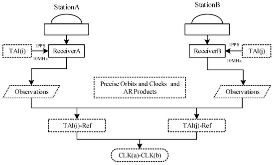
Figure 1.
Sketch map for PPPAR time-frequency transfer.
Firstly, determination of the difference between the clocks CLK(a) and CLK(b) connected to the receiver and the standard reference time (such as GPST, IGST, or UTC (NTSC)), performing the difference operation to obtain that difference, and then passing the calibration method (https://webtai.bipm.org/ftp/pub/tai/publication/gnss-calibration/guidelines (accessed on 1 October 2022)) to complete calibration of the hardware time delay. This paper’s clock difference is the outcome of ambiguity-fixed technology, which typically uses PPP technology. The alternative approach is as follows:
CLK(a) − CLK(b) = (CLK(a) − Ref) − (CLK(b) − Ref)
2.2. GNSS-PPPAR Model
The Equation (1) examples illustrate the main observations of GNSS raw pseudo-range and phase in Equation (2):
In Equation (2), represents pseudo-range observations; represents carrier-phase observations; r and j represents receiver and signal frequency, respectively; represents the geometric distance between the satellite and the receiver; represents the tropospheric Zenith Wet Delay (ZWD); represents ionospheric delay; and represents frequency j coefficient; and represent receiver and satellite clock difference, respectively; represents map projection function; is the integer phase ambiguity; means wavelength in frequency j; and are the pseudo-range and carrier-phase error term which did not quantize into the function model, respectively.
In Equation (2), and are the Uncalibrated Code Delay (UCD) and Uncalibrated Phase Delay (UPD) at the receiver; and are UCD and UPD at the satellite end. The general function model is the combination of Ionospheric-Free (IF). We define the coefficient as follows in Equation (3):
We assume Equation (4):
in Equation (4), Δ and represent constant and variable parts of hardware delay, respectively [24]. IF combined pseudo-range and carrier observations can be written as follows in Equations (5)–(7):
In Equation (7), is the Wide-Lane (WL) ambiguity and is the wavelength of the narrow-lane (NL) ambiguity. is called the NL ambiguity. Hatch–Melbourne–Wubbena (HMW) combination can be expressed as follows in Equation (8):
In Equation (8), is the WL wavelength. To eliminate the hardware delay at the receiver, PPPAR generally uses the method of an inter-satellite single difference (SD) method. The ambiguity of SD IF combination and WL ambiguity is expressed as follows in Equation (9):
The IGS satellite clock difference product absorbs the pseudo-range hardware delay. The satellite clock difference can be expressed as follows in Equation (10):
In Equation (10), represents satellite clock difference products, and represents the “real” clock difference of the satellite. To make use of this IF satellite clock product, we rewrite Equation (10) as Equation (11):
In Equation (11), is the DCB at the satellite end, which is . We substitute clock difference to obtain Equation (12):
And we assume Equation (13):
In Equation (13), will be submerged by pseudo-range noise and finally enter the pseudo-range residual. The IF combination’s ambiguity is divided into a linear combination of WL and NL in Equation (7). The WL is fixed first, followed by the NL, in the fixed ambiguity sequence. Following are the fixed stages [25]:
Firstly, determine the SD IF float ambiguity. Calculate the ambiguity parameters and the accompanying Variance-Covariance Matrix (VCM) by applying the error propagation approach to the standard extended Kalman filter (EKF) calculation in Equation (14):
In Equation (14), is a SD IF solution. is SD design matrix and is IF ambiguity VCM [·] indicates that this term can be eliminated by using PPPAR products.
Secondly, fixed SD WL ambiguity. The MW combination can be used to calculate the float solution to the WL ambiguity. The (OBS or FCB) product can then be used to obtain the integer solution. In general, it can also be rounded up directly in Equation (15).
In Equation (15), denotes fixed SD WL ambiguity and represents the average MW combination; the WL UPD is dispensable and can be eliminated using PPPAR products.
Thirdly, the SD NL ambiguity was fixed. Following a successful WL ambiguity correction, the expression equation for the SD NL term can be written as follows in Equation (16):
In Equation (16), is the SD float NL ambiguities which are obtained by applying the covariance propagation law. The NL UPD correction is required for the FCB method. Since NL ambiguities are strongly correlated in PPP, the popular Least-squares Ambiguity Decorrelation Adjustment (LAMBDA) method or a modified variant serves as the foundation of a search strategy. The widely used ratio test and success rate are used to decide what must be fixed.
Fourthly, Fixed SD IF ambiguity. After the SD WL and NL are successfully fixed, the SD IF can be recalculated to obtain in Equation (17):
In Equation (17), NL UPD correction is required for the FCB method.
Lastly, the fixed solution is updated. Other parameters can be updated by their correlation with fixed ambiguities, such as Position, ZWD, the clock difference parameters, and the remaining unfixed ambiguities addressed in Equation (18):
In Equation (18), and are fixed and unfixed parameters, respectively, is float solution with VCM , is the integer ambiguity, is the covariance matrix of and .
The receiver clock difference parameters in this paper are updated using Equations (18) and (19).
Equation (19) contains the position , zenith tropospheric delay , the clock difference parameters , and the remaining unfixed ambiguity . is the clock difference solved in this paper, made up of the parameters after the ambiguity is fixed.
In order to create 15 international time comparison links, this paper chooses 16 MGEX stations with external high-precision atomic clocks, uses AR product data from CNES, SGG, CODE, and PRIDE laboratories, and conducts high-precision time-frequency transfer experiments using three ambiguity-fixed strategies. Using the IGS final clock product as a benchmark and contrasting it with ambiguity-float.
3. Experimental Data and Processing Strategies
The BIPM (Bureau International des Poids et Measures) was founded in 1875. The information from more than 500 atomic clocks provided by BIPM to time laboratories across the world is weighted to produce the International Atomic Time (TAI). The PTB (Physikalisch-Technische Bundesanstalt) in Germany serves as the key node for the current international time comparison [26].
The chosen stations are primarily based on the following criteria: they must be participating stations in the BIPM international time comparison time laboratory, have a receiver attached to an ultra-reliable atomic clock, and have at least GPS, Galileo, and BDS system observations. In order to expand the scope of the test, we also selected some stations that did not participate in the international TAI comparison and did not have an external atomic clock but had an external high-precision time and frequency source.
Figure 2 illustrates the selection of experimental observation data from 16 globally dispersed sites. The MGEX FTP server served as the source of the observation data. Table 1 displays the specific setup information for these stations, including antennas and the different kinds of external atomic clocks.
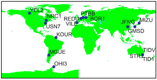
Figure 2.
The distribution map of 16 stations was selected, and each station is externally connected with a high-precision atomic clock.

Table 1.
Detailed configuration information table of 16 selected stations (from igs.org).
The publicly accessible PPPAR solutions produced by several agencies with three preset strategies are listed in Table 2. For the sake of conciseness, the terms “GRM”, “WUM”, “COM”, and “WHU” in the remaining sections of this article, respectively, stand for PPP AR products from CNES, SGG-WHU, CODE, and PRIDE laboratories. BDS-2 and QZSS FCB products are provided by SGG-WHU, and PRIDE laboratories supports BDS-2 and BDS-3 satellites for PPPAR [21]. This article’s data is based on information as of January 1, 2020. These three fixed techniques are referred to as FCB, IRC, and observable-specific code biases (OSBs) in the article that follows.

Table 2.
An overview of the PPP AR products.
4. PPP Detailed Processing Strategy
The detailed PPPAR strategy of the article is shown in Table 3 below.

Table 3.
PPPAR Detailed Policy.
It should be noted that this study employs the Kalman filtering technique. As a result, the PPP outcomes at the initialization stage were not significant. The PPP results are smoothed in this research by combining forward and reverse filtering with smoothing. Three steps make up the process: forward PPP filtering results, reverse PPP filtering results, and combining the first two results using the weighted average approach. This smoothing equation has the following in Equation (20):
In Equation (20), and are the variance matrix and state vector at time k, respectively. and correspond to the forward filtering result at time k, and are, respectively, the variance matrix and state vector corresponding to the reverse filtering result at time k; and are the variance matrix and state vector corresponding to the smoothed result at time k, respectively. The convergence time issue in the first stage of PPP or PPPAR is eliminated in this research using the bidirectional Kalman filter approach.
5. Validation and Analysis
5.1. Test Case
The ambiguity-fixed methods are FCB, IRC, and OSB. Due to the existence of precision orbit and clock products with various analysis centers, we use three fixed methods (FCB, IRC, and OSB) to create a system of six alternative ways to study our results. The following six categories for numerous items are determined by the three approaches (FCB, IRC, and OSB), as indicated in Table 4.

Table 4.
6 ways of 3 fixed strategies measures taken in this paper.
There is no convergence issue with the PPP approach because we employ the bidirectional filtering method for better analysis and comparison. The positioning outcome of the PTBB station is depicted in Figure 3. It is obvious that there is no convergence issue and that the convergence effect may always be obtained. It consistently maintains a 1 cm accuracy in three directions (NEU).
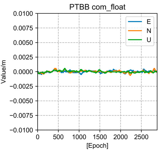
Figure 3.
Position results of bidirectional filtering of PTBB station.
Using various analysis center products, some academics have carried out positioning work [20,21]. To help with a better grasp of the overall logic, we also do the positioning results here. Three directions are divided (NEU), and the RMS display is displayed in Figure 4. We can observe that the ambiguity-fixed has a positive effect on the positioning if we use the SNX weekly solution as a point of reference. After the ambiguity is resolved, nearly all solutions produce superior positioning outcomes. The performance of GBM is the finest among them and the localization outcomes are exceptional.
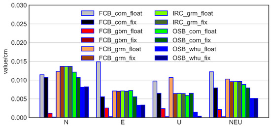
Figure 4.
6 methods of 3 fixed strategies’ (FCB, IRC, OSB) positioning results, including three directions of NEU and RMS value composed of three directions.
We are aware that there is a strong association between the U direction and clock difference [22]. We assume that the clock difference operates more effectively because the U direction is enhanced. On the basis of this concept, we continue to solve the clock difference result after the ambiguity has been resolved. With 16 stations, it is clear that the ambiguity-fixed method is quite effective at containing those diverging points. In Figure 5, we display PTBB station clock differences of the three techniques (FCB, IRC, and OSB).
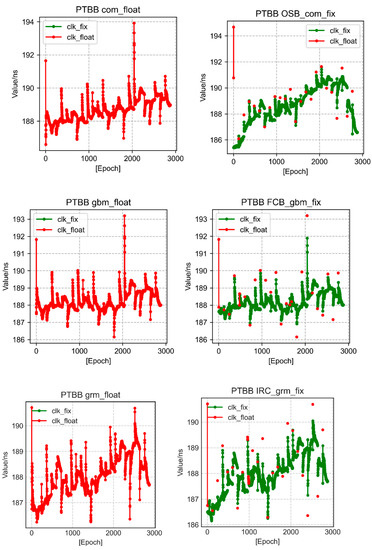
Figure 5.
Three strategies of PTBB station results with fixed and floating ambiguity clock difference, where red represents floating point and green represents fixed solution.
No matter which fixing technique is employed, all of them are identical to the location and may successfully revert some points of clock discrepancy, as illustrated in Figure 5. We conducted further investigations to determine the magnitude of the impact effect.
We measured the STD box display of the 16 stations by comparing it to the final clock difference of the IGS week SNX file. Figure 6 illustrates how we confirmed our hypothesis that, with the exception of OSB_ com’s fixed strategy, all other fixed strategies have lower STDs for fixed clock difference than for the float solution.
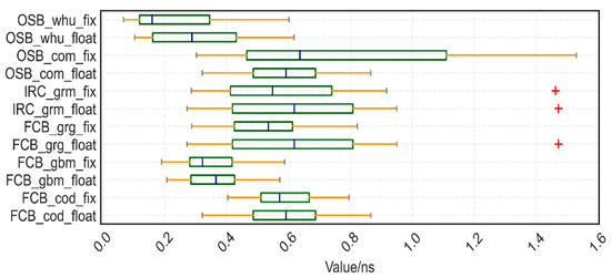
Figure 6.
The STD box display of the 16 stations we choose to take the final clock difference of the IGS week SNX file as a reference, red ”+” stands for outliers.
As the outcome of the clock difference improves, the time transfer also does, and we can now move on to the study of time linkages made up of two stations.
We create the 15 worldwide time comparison connections mentioned above using the PTBB station as the basis. Due to space restrictions, Figure 7 shows the sequence diagrams for the two time-links, PTBB−MGUE and PTBB−USN7. It is clear that the fixed approach, particularly when using WHU goods, has a particular smoothing effect on unfixed.
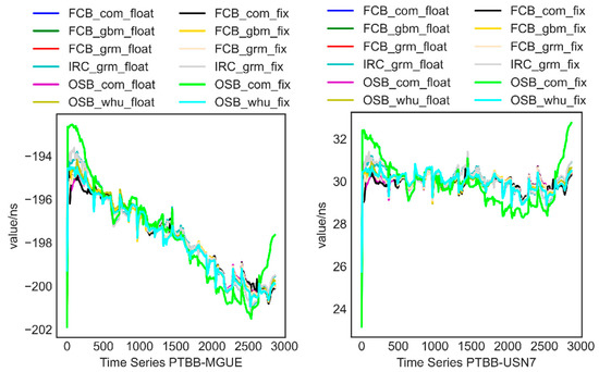
Figure 7.
PTBB-MGUE/PTBB-USN7 Time links with different strategies.
We estimated the STD of the time transfer to assess the Type A uncertainty in the remote time-transfer link using the time-transfer results and calculation of station clock difference acquired from the IGS final product as a reference. For a single GPS, the time stability STD of time transfer is enhanced using various ambiguity-fixing procedures, and the improvement ranges from 10 to 40% in the Figure 8 STD box display of 15 time-links. The one with the most improvement, up to 40%, is FCB_grm. OSB_com is the unconventional strategy. In the instance of a single station (Figure 6), one exception has already occurred, and a bigger exception follows the creation of the time connection.
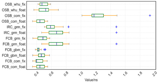
Figure 8.
The STD box display of 15 time-links takes the final clock difference of the IGS week SNX file as a reference; blue “+” stands for outliers.
The frequency stability of the time-links between the PPP and PPPAR results should then be examined. The results of PPP and PPPAR alter in the same manner for the transfer at the same moment (Figure 7). The PPPAR results’ variability is minimal in comparison. We examine time linkages’ frequency stability. To examine the frequency stability of time series, we employ the Allan variance modification technique and the following equations:
The above Equations (21) and (22), is the interval time, and the maximum can only be half of the number of data, representing the phase data.
Due to space constraints, we are only able to demonstrate the features of six common time-links (PTBB−BOR1, PTBB−GMSD, PTBB−NRC1, PTBB−OHI3, PTBB−TID1, PTBB−TIDV). Figure 9 makes it clear that the frequency stability of the time link has only slightly improved as a result of the ambiguity-fixed technique. We discovered that between 1000 and 10,000 s, OSB com fix, IRC_ grm_ float, and IRC grm fix all perform poorly.
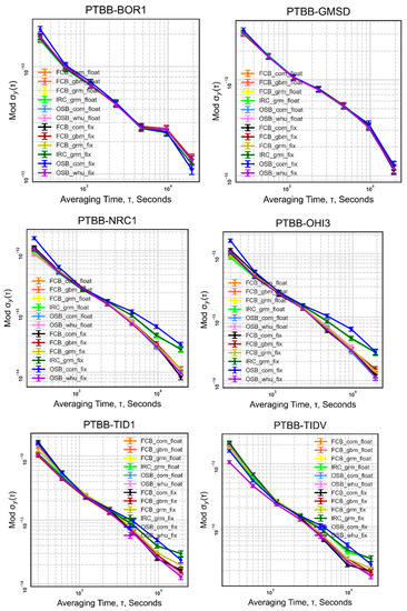
Figure 9.
Frequency stability statistics of 6 time-links (PTBB-BOR1, PTBB-GMSD, PTBB-NRC1, PTBB-OHI3, PTBB-TID1, PTBB-TIDV).
Go one step further; in an ordinary clock time link, stations participating in time transfer share the same atomic clock. The relative clock skew from station to station will be eliminated. The standard can directly calculate the deviation to evaluate the time transfer performance. Taking TIDV-TID1 as an example, as shown in Figure 10, we can’t get the conclusion that its frequency stability of fixed ambiguity is better than that of the float in terms of short-term stability.
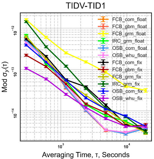
Figure 10.
Frequency stability statistics of TIDV-TID1 time link with common clock.
5.2. Muti-GNSS
Researchers have carried out pertinent experiments. The results of the time-frequency transfer are enhanced by the multi-GNSS PPP approach [30]. This section’s goal is to demonstrate this for the multi-GNSS PPPAR technique time transfer. When using multiple systems, we take GPS as the benchmark, and the system differences between other systems and GPS are estimated by parameters.
We developed six schemes and fifteen particular comparison methods, as indicated in Table 5, in accordance with various ambiguity-fixed strategies and the satellite system integrated into the product. Following a set strategy-based division into FCB, IRC, and OSB, the products are then further categorized into six schemes. Additionally, there are 15 precise fixed methods in the bundled Satellite system. GEC denotes the addition of BDS based on GPS and Galileo. G indicates for single GPS. GE stands for GPS plus Galileo.

Table 5.
15 detailed fixed strategies for multi-system.
With only a minimal addition of satellite systems, we used the same PPP ambiguity fixing approach as in the preceding section. In a similar manner, we solve 16 stations, create 15 time-links centered on PTBB, and determine the STD with respect to the clock difference of the IGS weekly solution stations. The outcomes are displayed in Figure 11.
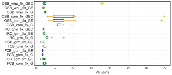
Figure 11.
Muti-GNSS PPPAR time links STD concerning the clock difference of IGS weekly solution stations; yellow ”+” stands for outliers.
As illustrated in Figure 11, with the exception of the COM product approach employing a single GPS, the statistical results of time link STD of PPPAR, whether single-system or multi-system, can be maintained at the sub-nanosecond level; the six GE combinations have improved compared to the single GPS after the addition of the Galileo system, and the improvement ranges from two to nine percent; the GEC combo has improved the majority of methods while weakening a few others. Inspection reveals that it is caused by some stations’ subpar BDS fixes.
Due to physical constraints, we can only provide the frequency stability data of the four distinct Muti-GNSS PPPAR temporal links in Figure 12. The integration of multiple systems (Galileo, BDS) causes a significant shift in frequency stability, which is slightly different from the single system GPS. Even so, some are weakened after being corrected, while some are completely unaffected, and some are even better. We believe that despite the system’s gain in short-term stability, the stability has not been greatly enhanced based on the comparison of multiple groups of linkages.
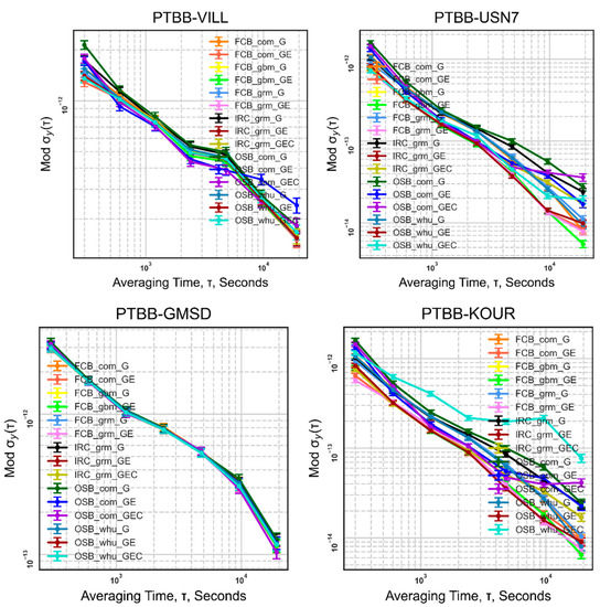
Figure 12.
Frequency Stability statistics of Muti-GNSS PPPAR time links (PTBB-VILL, PTBB-USN7, PTBB-GMSD, PTBB-KOUR).
6. Conclusions
This paper examined 16 MGEX stations with external high-precision atomic clocks to form 15 time comparison links and uses AR products data from CNES, SGG, CODE, and PRIDE laboratories. It then used three ambiguity resolution strategies (FCB, IRC, OSB) to conduct high-precision time-frequency transfer experiments in order to thoroughly evaluate the impact of various strategies and AR products.
We arrived at the following findings by using the IGS end clock product as a reference and contrasting it with the float solution. With various ambiguity-fixing procedures, the time stability STD of time transfer is increased for a single GPS, and the improvement ranges from 10 to 40%. Of these, FCB_grm has undergone the greatest improvement, up to 40%; frequency stability has barely changed. When compared to a single GPS, combinations have improved with the addition of the Galileo system, and the improvements range from 2 to 9%. The majority of methods have improved, while a few techniques have weakened with the GEC combination. We feel that the increased short-term stability of the system has not significantly enhanced stability based on the comparison of multiple groups of links. This research provides an important reference for future PPPAR time-frequency transmission engineering applications.
Author Contributions
M.O. and X.Z. conceived and designed the experiments; M.O. performed the experiments, analyzed the data, and wrote the paper; X.Z., R.Y. and D.L. contributed to discussions and revisions. All authors have read and agreed to the published version of the manuscript.
Funding
This work was supported by the National Key R&D Program of China (Grant No. 2021YFA0716500), the National Natural Science Foundation of China (Grant No. 61973328, 91938301), and the Key Basic Research Projects of Shenzhen Science and Technology Commission (Grant No. 2020N259), Shenzhen Science and Technology Program (Grant No. GXWD20201231165807008, 20200830225317001), and was also supported by Shenzhen Key Laboratory of Navigation and Communication Integration (Grant No. ZDSYS20210623091807023).
Data Availability Statement
Not applicable.
Conflicts of Interest
The authors declare no conflict of interest.
References
- Zhang, H.; Yan, M.; Guang, W. Comparison of two-way and beidou common view time transfer between ntsc and beij station. Adv. Mater. Res. 2014, 1049–1050, 1997–2000. [Google Scholar] [CrossRef]
- Nawrocki, J.; Lewandowski, W.; Nogas, P.; Foks, A.; Lemanski, D. An experiment of GPS + GLONASS common-view time transfer using new multi-system receivers. In Proceedings of the Frequency and Time Forum (EFTF), 2006 20th European IEEE, Braunschweig, Germany, 27–30 March 2006. [Google Scholar]
- Allan, D.W.; Weiss, M.A. Accurate Time and Frequency Transfer During Common-View of a GPS Satellite. In Proceedings of the IEEE Symposium on Frequency Control, Vancouver, Canada, 29–31 August 2005. [Google Scholar]
- Harmegnies, A.; Defraigne, P.; Petit, G. Combining gps and glonass in all-in-view for time transfer. Metrologia 2013, 50, 277–287. [Google Scholar] [CrossRef]
- Petit, G.; Jiang, Z. Gps all in view time transfer for tai computation. Metrologia 2007, 45, 35. [Google Scholar] [CrossRef]
- Petit, G. The TAIPPP pilot experiment. In Proceedings of the IEEE International Frequency Control Symposium, 2009 Joint with the 22nd European Frequency and Time Forum, Besancon, France, 20–24 April 2009. [Google Scholar]
- Zhang, V.S.; Parker, T.E.; Jian, Y. Long-term uncertainty in time transfer using GPS and TWSTFT techniques. In Proceedings of the Frequency Control Symposium the European Frequency Time Forum, Denver, CO, USA, 12–16 April 2015. [Google Scholar]
- Ray, J.; Senior, K. Geodetic techniques for time and frequency comparisons using gps phase and code measurements. Metrologia 2005, 42, 215. [Google Scholar] [CrossRef]
- Petit, G.; Kanj, A.; Loyer, S.; Delporte, J.; Mercier, F.; Perosanz, F. 1 × 10⁻¹⁶ frequency transfer by gps ppp with integer ambiguity resolution. Metrologia 2015, 52, 301. [Google Scholar] [CrossRef]
- Zumberge, J.F.; Heflin, M.B.; Jefferson, D.C.; Watkins, M.M.; Webb, F.H. Precise point positioning for the efficient and robust analysis of GPS data from large networks. J. Geophys. Res. Solid Earth 1997, 102, 5005–5017. [Google Scholar] [CrossRef]
- Su, K.; Jin, S.; Ge, Y. Rapid displacement determination with a stand-alone multi-GNSS receiver: GPS, Beidou, GLONASS, and Galileo. GPS Solut. 2019, 23, 54. [Google Scholar] [CrossRef]
- Lu, C.; Li, X.; Nilsson, T.; Ning, T.; Heinkelmann, R.; Ge, M.; Glaser, S.; Schuh, H. Real-time retrieval of precipitable water vapor from gps and beidou observations. J. Geod. 2015, 89, 843–856. [Google Scholar] [CrossRef]
- Gao, Z.; Zhang, H.; Ge, M.; Niu, X.; Shen, W.; Wickert, J.; Schuh, H. Tightly coupled integration of multi-gnss ppp and mems inertial measurement unit data. Gps Solut. 2017, 21, 377–391. [Google Scholar] [CrossRef]
- Li, X.; Ge, M.; Guo, B.; Wickert, J.; Schuh, H. Temporal point positioning approach for real-time gnss seismology using a single receiver. Geophys. Res. Lett. 2013, 40, 5677–5682. [Google Scholar] [CrossRef]
- Laurichesse, D.; Mercier, F.; Berthias, J.P.; Broca, P.; Cerri, L. Integer ambiguity resolution on undifferenced gps phase measurements and its application to ppp and satellite precise orbit determination. Navigation 2009, 56, 135–149. [Google Scholar] [CrossRef]
- Ge, M.; Gendt, G.; Rothacher, M.; Shi, C.; Liu, J. Resolution of gps carrier-phase ambiguities in precise point positioning (ppp) with daily observations. J. Geod. 2008, 82, 389–399. [Google Scholar] [CrossRef]
- Collins, P.; Bisnath, S.; Lahaye, F.; Héroux, P. Undifferenced gps ambiguity resolution using the decoupled clock model and ambiguity datum fixing. Navigation 2010, 57, 123–135. [Google Scholar] [CrossRef]
- Shi, J.; Gao, Y. A comparison of three ppp integer ambiguity resolution methods. Gps Solut. 2014, 18, 519–528. [Google Scholar] [CrossRef]
- Geng, J.; Meng, R.; Dodson, R.H.; Teferle, R.N. Integer ambiguity resolution in precise point positioning: Method comparison. J. Geod. 2010, 84, 569–581. [Google Scholar] [CrossRef]
- Glaner, M.; Weber, R. Ppp with integer ambiguity resolution for gps and galileo using satellite products from different analysis centers. GPS Solut. 2021, 25, 102. [Google Scholar] [CrossRef]
- Chen, C.; Xiao, G.; Chang, G.; Xu, T.; Yang, L. Assessment of gps/galileo/bds precise point positioning with ambiguity resolution using products from different analysis centers. Remote Sens. 2021, 13, 3266. [Google Scholar] [CrossRef]
- Ouyang, M.; Li, J.; Li, W.; Ge, Y.; Dai, Z. Research on time and frequency transfer during ppp convergence with parameters correlation comparison. Measurement 2020, 173, 108597. [Google Scholar] [CrossRef]
- Lyu, D.; Zeng, F.; Ouyang, X.; Zhang, H. Real-time clock comparison and monitoring with multi-gnss precise point positioning: Gps, glonass and galileo sciencedirect. Adv. Space Res. 2020, 65, 560–571. [Google Scholar] [CrossRef]
- Zhao, L.; Ye, S.; Jia, S. Handling the satellite inter-frequency biases in triple-frequency observations. Adv. Space Res. 2017, 59, 2048–2057. [Google Scholar] [CrossRef]
- Liu, S.; Sun, F.; Zhang, L.; Li, W.; Zhu, X. Tight integration of ambiguity-fixed ppp and ins: Model description and initial results. GPS Solut. 2016, 20, 39–49. [Google Scholar] [CrossRef]
- Defraigne, P.; Aerts, W.; Pottiaux, E. Monitoring of utc(k)’s using ppp and igs real-time products. Gps Solut. 2015, 19, 165–172. [Google Scholar] [CrossRef]
- Sastamoinen, J. Atmospheric correction for troposphere and stratosphere in radio ranging of satellites, in the use of artifical satellites for geodesy. Geophys. Monogr. Ser. 1972, 15, 247–252. [Google Scholar]
- Kouba, J. Testing of global pressure/temperature (gpt) model and global mapping function (gmf) in gps analyses. J. Geod. 2009, 83, 199–208. [Google Scholar] [CrossRef]
- Petit, G.; Luzum, B. Iers Conventions IERS Technical Note; Bonifatius GmbH: Paderborn, Germany, 2010. [Google Scholar]
- Ge, Y.; Dai, P.; Qin, W.; Yang, X.; Zhou, F.; Wang, S.; Zhao, X. Performance of multi-gnss precise point positioning time and frequency transfer with clock modeling. Remote Sens. 2019, 11, 347. [Google Scholar] [CrossRef]
Disclaimer/Publisher’s Note: The statements, opinions and data contained in all publications are solely those of the individual author(s) and contributor(s) and not of MDPI and/or the editor(s). MDPI and/or the editor(s) disclaim responsibility for any injury to people or property resulting from any ideas, methods, instructions or products referred to in the content. |
© 2022 by the authors. Licensee MDPI, Basel, Switzerland. This article is an open access article distributed under the terms and conditions of the Creative Commons Attribution (CC BY) license (https://creativecommons.org/licenses/by/4.0/).