Abstract
Millimeter wave (MMW) radar simultaneous localization and mapping (SLAM) technology is an emerging technology in a tunnel vehicle accident rescue scene. It is a powerful tool for statistic-trapped vehicle detection with limited vision caused by darkness, heat, and smoke. A variety of SLAM frameworks have been proven to be able to obtain 3-degree-of-freedom (3-dof) pose estimation results using 2-dimention (2D) MMW radar in open space. In the application of millimeter wave radar for pose estimation and mapping in a closed environment, closed space structures and artificial targets together constitute high-intensity multi-path scattering measurement data, leading to radar false detections. Radar false detections caused by multi-path scattering are generally considered to be detrimental to radar applications, such as multi-target tracking. However, few studies analyze the mechanism of multi-path effects on radar SLAM, especially in closed spaces. In order to address the problem, this paper first presents a radar multi-path scattering theory to study the generation mechanism difference of false and radar true detection and their influences on radar SLAM 2D pose estimation and mapping in tunnel. According to the scattering mechanism differences on SLAM, a radar azimuth scattering angle signature is proposed, which allows distinguishing radar false detections from real ones. This is useful in avoiding using unreliable radar false detections to solve a radar SLAM problem. In addition, two different radar false detection revising methods combined with the CSM (correlative scan matching) algorithm are proposed in this paper. The HTMR-CSM (hard-threshold-multi-path-revised correlative scan matching) algorithm only depends on a hard threshold of radar azimuth scattering angle signature to eliminate all radar false detections as much as possible before CSM. Another idea is the STMR-CSM (soft-threshold-multi-path-revised correlative scan matching) algorithm. All the radar false detections are classified according to the distribution model of radar azimuth accuracy, and part of more reliable radar false detections are retained to estimate a more accurate pose. All the ideas in this paper are validated by using an MMW 2D radar mounted on a rail-guided robot in a tunnel. Two cars on fire were set as the targets. The experimental results show that the STMR-CSM algorithm that keeps the reliable radar false detections improves the positioning accuracy by 20% compared with CSM.
1. Introduction
With the rapid development of the economy and transportation, more and more cities have begun to build tunnels. At present, tunnels are getting longer and longer. The longer the tunnel, the greater the possibility of traffic accidents. The probability of fire will also increase. In the event of a fire, smoke and particles will diffuse throughout the space, in a serious threat to people’s lives and property safety. As smoke and particles spread throughout the space, it can be difficult for rescuers to reach the fire site in the first place. The difficulty of rescue work greatly increases. Therefore, a robot is urgently needed to replace people to reach scenes of fire for the first time. Localization and mapping of the scene help people find out the scene to facilitate the organization of rescue work [1,2,3].
SLAM technology has become the core technology of unmanned driving. SLAM refers to the main body equipped with sensors to establish the surrounding environment through motion in an unknown environment, at the same time estimating their own movement process to achieve localization [4]. Sensors mainly include optical cameras, lidar and millimeter wave radar. Optical cameras and lidar are the most common sensors. The optical camera is the main sensor of V-SLAM, and lidar is the main sensor of lidar SLAM [5,6]. The optical camera has the advantages of a large amount of information, rich texture and small size, but it is susceptible to light and extreme weather. Lidar can work in more diverse scenarios than the optical camera. However, it still cannot work stably in smoke and fog. These scenes reduce the accuracy of localization and mapping [7,8]. In order to apply SLAM technology to extreme scenes such as fire, smoke and fog, we do not choose optical cameras and lidar. Millimeter wave radar is selected as the sensor in this paper. Millimeter wave radar transmits electromagnetic waves, which can penetrate fire, smoke and fog to detect targets. It is not affected by light. It can work all day and in all weather. However, millimeter wave radar angle resolution is low. It is prone to noise points. In addition, the number of point clouds is less than the lidar [6,9,10]. Therefore, SLAM technology based on millimeter wave radar has been widely studied [11].
At present, the research of millimeter wave radar SLAM is not as mature as lidar SLAM, but their principles are similar. There have been many studies on lidar SLAM. SLAM algorithm has strict requirements on the initial value. Iterative closest point (ICP) is a point cloud matching method [12]. In [13], the original ICP was improved, and a point-to-line matching iterative closest point (PLICP) was proposed. The ICP algorithm only considers the point-to-point distance. It lacks the use of point cloud structure information, which will lead to a decrease in point cloud matching accuracy. Compared with the classical ICP, PLICP transforms the distance between points into the distance between points and lines. However, this method is sensitive to local minima. Therefore, there are higher requirements for the initial value, and a poor initial value affects the accuracy. SLAM algorithm is based on feature point matching. It includes Loam, A-Loam, LeGo-Loam and Loam-Livox [14,15,16]. They process the original point cloud and extract the feature point cloud using the feature point cloud to complete positioning and mapping. They have strict requirements for the scene. They are extremely prone to degradation in tunnels, resulting in reduced positioning and mapping accuracy. The above algorithms are based on the research of open environments. However, correlative scan matching (CSM) is a global scan-matching algorithm that avoids the local extremum problem [17]. Because it does not believe the global maximum found by local search. It searches for an entire reasonable area. This region comes from a priori or can be obtained from other sensors. In addition, it does not need to extract feature points because it has lower requirements for the scene and can be applied in the closed space of the tunnel.
When millimeter wave radar detects targets in a closed space, the electromagnetic waves will have multiple reflection paths to generate radar false detections. This phenomenon will be more obvious when the target in the detection environment is small or less. The number of radar false detections can even exceed the real target point clouds, reducing the accuracy of measurement [18]. The original radar point cloud data cannot meet the corresponding perception requirements. They affect the accuracy of SLAM, and it is necessary to process the clutter and radar false detections in the data.
In paper [19], the method of clustering each scan is adopted. After clustering, the average value of each cluster data set is taken as its center. Point clouds in radar data are sparse, and there are many stray points and uneven density, so partition clustering methods (such as K-Means) and hierarchical clustering algorithms are not suitable for processing radar data. A grid-based DBSCAN algorithm was proposed in the paper [20]. Firstly, the calculation of the density criterion of DBSCAN is given. Then the grid-based DBSCAN is modified. In paper [21], DBSCAN is proposed to filter the clutter points by using the RCS value of the target as the feature. This method solves the problem that the parameters need to be determined manually in the proposed method [22]. It improves the accuracy of clutter recognition. These methods can effectively remove clutter points. These methods are based on the Poisson distribution assumption. However, there are great challenges when clutter and radar false detections are stronger than real point clouds. These methods deal with clutter points or radar false detections but do not study the impact of multi-path on SLAM. However, some references studied the positive role of multi-path in positioning [23]. At present, there is a lack of research on the positive impact of multi-path in millimeter wave radar SLAM.
Aiming at the problems existing in the existing methods of screening out millimeter wave radar false detections. The technical approach of this paper is to first establish a radar SLAM multi-path scattering theory in the tunnel. Then, the radar false detections are identified according to the azimuth range characteristics of the scattering point. Finally, the method of reliable radar false detection recognition is added to SLAM. A radar false detection revision CSM algorithm is proposed. The contributions of this paper are mainly the following three points:
- The multi-path scattering theory of SLAM in a tunnel is established. Combined with the actual scene of tunnel and the target, a multi-path scattering theory is constructed to illustrate the generation mechanism of radar false detections. The accumulation process of single-bounce, double-bounce and triple-bounce in SLAM is constructed.
- According to the scattering mechanism differences on SLAM, we propose a radar azimuth scattering angle signature. The calculation method of azimuth scattering angle and range of target point based on SLAM is given. According to the range of azimuth scattering angle, all radar false detections are identified for revision.
- HTMR-CSM and STMR-CSM are proposed. The scan-to-scan point cloud matching method of the original CSM algorithm is improved. A point cloud matching mode from scan-to-submap is proposed. STMR-CSM further optimizes HTMR-CSM by using reliable radar false detections to improve positioning accuracy. HTMR-CSM as a control group demonstrated the effectiveness of STMR-CSM. In addition, it improves the accuracy of the map.
The second section of this article mainly establishes the SLAM multi-path scattering theory of radar in the tunnel and analyzes the difference of different bounces in the stability of the SLAM accumulation process. The third section introduces radar azimuth scattering angle signature. The fourth section introduces HTMR-CSM and STMR-CSM. The point cloud matching mode of the original CSM is improved. The fifth section is mainly the experimental results and analysis through multi-dimensional comparison to prove the effectiveness of this method. The last section mainly summarizes the article and looks forward to the future.
2. Influence of Millimeter Wave Radar Scattering Characteristics on SLAM
Millimeter wave radar SLAM technology relies on estimating radar pose by continuously observing the same scatterer in different locations. The more stable observation times accumulated for the same scatterer, the more favorable it is for the algorithm to overcome the observation error and obtain an accurate estimation of radar pose. Three main radar scattering characteristics may affect the accuracy of radar SLAM pose estimation.
2.1. Target Scattering Type Characteristic
Firstly, whether the radar can stably observe the same scatterer in different locations not only requires visibility (unobtrusive) but also depends on the type of scatterer. The Radar Cross Section (RCS) of the scatterer varies with the radar incidence angle, which makes it possible to detect a point target when the echo power is higher than the Constant False Alarm Rate Detector (CFAR) threshold. According to the RCS varying with incident angle, different types of scatterers can form different ranges in azimuth, continuous or discontinuous. This results in different angular ranges of scatters, at which point clouds can be detected in azimuth, as shown in Figure 1. The convex surface formed by most of the vehicle body and the horizontal ground can be considered a typical dihedral corner reflector. It can be observed in a radar azimuth range of not less than 100 degrees. The ideal sphere reflectors can even be observed in a 360-degree radar azimuth range. In contrast, there are also smooth surface scatterers dominated by specular reflection, whose radar azimuth observable angle range is much smaller. Therefore, the acquisition of radar data should consider the characteristics of the scene, maximize the accumulation of azimuth angle range, and optimize the radar geometry, antenna pattern design and movement route.
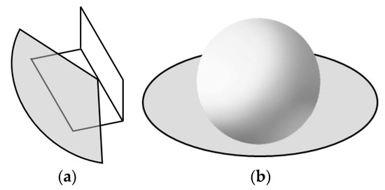
Figure 1.
Comparison of the azimuth angle of different types of scatterers. (a) Dihedral corner reflector with more than 100-degree radar azimuth range. (b) Spheres reflector with 360-degree radar azimuth range.
2.2. Polarization Rotation Characteristic
The mechanism that rotates the polarization of multi-bounce radar returns is another main feature that affects radar echo power. According to the typical dihedral reflector double-bounce polarization scattering model, if the angle α (see Figure 2) between the direction of radar motion and the intersection direction of the two surfaces of the dihedral angle changes, the polarization rotation angle of the electromagnetic wave will also change [24]. Even if the RCS of the scatterer remains stable within a certain azimuth range, the angle rotation will make the radar echo power change nonlinearly, and the changes of different polarization channels are different. If the radar has full polarization measurement capability, the change of polarization rotation angle can be measured, and then the inverse rotation matrix inverse transformation is introduced to compensate for this change to maintain stability. However, MMW radars, which are mainly used for autonomous driving, are often single-polarized radars and do not have the ability to compensate for polarization rotation. Therefore, avoiding drastic changes in the direction of movement of the radar during the SLAM process will also help the radar to stably accumulate observations of the same target.
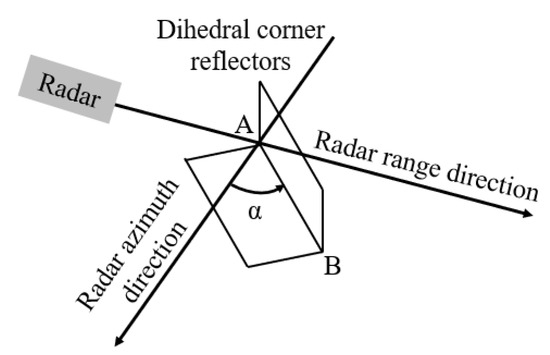
Figure 2.
Dihedral reflector and radar scattering geometry scheme.
2.3. Radar Slant Range of Multiple Bounce Scattering Characteristic
In addition to the target scattering type and polarization rotation, the slant range of multiple bounce scattering will also have an important impact on the accuracy of radar SLAM pose estimation. Radar electromagnetic scattering may be single-bounce and multiple-bounce in closed spaces such as indoors and in tunnels. The single-bounce scattering is directly reflected by the target. The multi-bounce scattering is reflected between the target, ground and wall more than once [25,26,27,28].
The main scattering paths can be seen in Figure 3 and are described below:
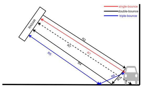
Figure 3.
Schematic diagram of main scattering paths.
Single-bounce scattering: The transmitting and receiving path is R1 → R1 which is shown by the red path in Figure 3. The single-bounce scattering slant range of the target is
Double-bounce scattering: The transmitting and
receiving path is R2 → R3 → R4 which is shown by the black path in Figure 3. This path can be equivalent to R7 → R7.
The double-bounce scattering slant range Rdouble of the target
is
Triple-bounce scattering: The transmitting and
receiving path is R5 → R6 → R6 → R5 which is shown by the blue path in Figure 3. The triple-bounce scattering slant
range Rtriple of
the target is
In the above three cases, when radar detects the point clouds from the same target at any place, there will be no additional slant range induced by multi-path or multiple bounce scattering. The slant range variation of the target will be stably related to the radar pose variation, independent of the additional path of multiple bounce scattering. Although there is a certain difference in the scattering slant range in these three cases, this difference is relatively stable during radar motion, which will only cause the contour of the vehicle target in the grid map to be widened, and will not lead to serious radar pose estimation errors.
Four and more times bounce scattering: The four and more times bounce transmitting and receiving path is R2 → n × R3 → R4, where n is the number of bounces between the vehicle body and the horizontal ground. The four and more times bounce slant range of the target is
where is the additional slant range induced by multi-path or multiple bounce scattering, and the additional slant range makes radar detect false detections and point clouds.
Figure 4 shows the differences of detected radar point clouds of the same target in the process of radar movement P1 to P3 with different scattering paths. As there is no additional slant range in Equations (1)–(3), the detected points of single, double, and triple-bounce scatterings overlapping together can be expressed as the red color point R. P1R, P2R, and P3R are the true ranges between radar and target. According to Equation (4), RY1, RY2 and RY3 are the additional slant ranges , which make the false detection slant range longer than the true ranges along each original radar range direction to the yellow points Y1, Y2 and Y3. They cannot be overlapped together like the point R. If n2, the number of bounces is bigger than n1, and the additional slant range will be bigger too. Therefore, the spread range among false detection point clouds B1, B2 and B3 is larger than that among point clouds Y1, Y2 and Y3.
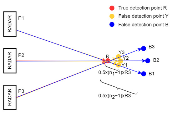
Figure 4.
The scheme of detected radar point clouds of the same target in the process of radar movement with different scattering paths.
In a SLAM problem, the point clouds B1, B2 and B3 may be assumed to be generated by the same point target. This depends on the size of the coordinate grid and the optimal SLAM pose search range. In a statistical way, it will make the additional slant range be transmitted reversely to the estimated pose of the radar, thereby introducing an estimation error, or even making the SLAM problem unsolvable, as shown in Figure 5.
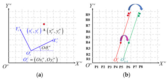
Figure 5.
(a) Schematic diagram of coordinate system conversion. (b) Schematic diagram of the false detection points’ impact on CSM MAP estimation.
At time t, the coordinate of point A which is represented in the radar local measurement coordinate system, is (shown in blue color). Point A, which is also represented in the SLAM global occupied grid coordinate system (shown in black color), is . According to the SLAM principle, the point cloud obtained by millimeter wave radar at different poses should be converted to the global occupied grid coordinate system using Equation (5).
where is the radar pose to be estimated at time t, and it is also represented in the SLAM global occupied grid coordinate system. The point cloud data measured by the radar of one scan is defined as . Then, the maximum a posteriori (MAP) estimation of unknown state can be obtained by using Equation (6).
In Equation (6), the likelihood function plays a key role on the state estimation, which uses all the history radar measurements , which are calculated by radar pose guess value and detection points using Equation (5). For the convenience of analysis, it can be considered that in the process of solving the SLAM problem, the set of radar pose guess values is obtained by dividing the grid of a specific size in the global pose space and traversing it on a certain range of grids. The argmax processing is operated by correlative scan matching (CSM). According to the output of Equation (5), the number of times each grid is hit is counted and normalized as in the global occupied grid coordinate system. Therefore, calculated using different radar pose guesses is different. Finally, the pose guess value that can maximize is selected as the MAP of radar pose .
In the measured radar point cloud, the more the number of true detection point clouds, the more accurate the MAP estimation of radar pose. When the number of false detection point clouds is large because of the multiple bounce scattering, the actual pose is difficult to maximize during CSM processing, especially as the spread range caused by the additional slant range is larger than the preset grid size. This will lead to MAP estimation error and even pose estimation failure, as shown in Figure 5b.
Assume that there is one point target in the scene, and the radar moves one grid from (R1, P4) to (R1, P5). Let the point cloud observed at time t be in (R4, P5), represented by red color. The point cloud observed at time is represented by green color in (R4, P6). If there is an additional multiple bounce slant range in return, the false detection point cloud is distributed in (R9, P6) and (R9, P8). When the CSM guesses the radar moving position from (R1, P4) to (R1, P5) (the actual radar position), the number of points hitting the same grid is 2. When guessing the radar moving position from (R1, P4) to (R1, P6) (wrong radar position), the number of points hitting the same grid is 4, and (R1, P6) will be the MAP estimation of CSM. It is worth noting that if the additional slant range is smaller, the MAP estimation result will be consistent with the true value, and the true detection points and the false detection points together constitute more observation samples, which is more conducive to reducing the randomness error of radar measurement. This conclusion will be used to improve the CSM algorithm.
3. Radar Azimuth Scattering Angle Based False Detections Recognition
Radar false detections are unstable and irregular. It will not only affect the accuracy of radar SLAM pose estimation but also cause false targets on the occupancy grid map. Therefore, they need to be revised. Radar false detections and radar true detections have obvious differences in azimuth scattering angle. This section describes a method of identifying radar false detections based on multi-path scattering theory combined with azimuth scattering angle.
The method not only solves the problem of incomplete radar false detection suppression in the complex scene of the original model-based method but also avoids the complex problem of the data-driven method [29].
3.1. Azimuth Scattering Angle of Point Target
The target can be detected by radar within a certain range. This range is defined as the azimuth scattering angle. It is related to the geometric relationship between radar and target. Different targets are different. In SLAM, radar is constantly moving. Therefore, targets can only be detected within a certain range. The detected range is called the azimuth scattering angle range in this paper.
First, the CSM algorithm is used to match the original data. Radar points of each scan are mapped on the occupancy grid map. We can obtain the grid coordinates of all points on the grid map. The pose of radar at each moment can also be obtained. Therefore, the azimuth scattering angle of each point can be calculated. We analyze the range of the azimuth scattering angle to identify the radar false detections:
is the pose coordinate of radar at scan. is the pose coordinate of the radar at scan. is the grid coordinate of a point. The black point represents a radar point in Figure 6.
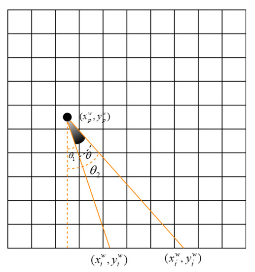
Figure 6.
Schematic diagram of azimuth scattering angle range.
The minimal azimuth scattering angle of the point cloud at scan is:
The maximum azimuth scattering angle of the point cloud at scan is:
Therefore, the azimuth scattering angle range of this point is
3.2. Radar False Detections Recognition
Figure 4 in the second section of this paper shows that the radar detects the same target at different positions. The red target is radar true detection. We calculate the maximum azimuth scattering angle and minimum azimuth scattering angle of the same target according to the calculation method in Section 3.1. In addition, we calculate the range of the azimuth scattering angle. In this case, the range of the azimuth scattering angle range is greater than 0. Figure 4 shows that when the radar detects the same target at different positions, affected by more times bounces, there will be radar false detections. They are random and disorderly. After point cloud matching, they will occupy different grids. When calculating the maximum azimuth scattering angle and the minimum azimuth scattering angle, it is found that the angle is the same or very close, and their scattering angle range is 0 or very close to 0. Points with an azimuth scattering angle range of 0 or close to 0 are regarded as radar false detections.
4. Millimeter Wave Radar SLAM Based on Radar False Detections Revising
For a SLAM problem, many studies have been carried out for both Lidar and MMW Radar. An important part of SLAM technology is scan matching through point clouds of different scans. Motion estimation is performed by the transformation relationship of different scan point clouds. Low-precision point clouds and unreliable radar false detections affect the accuracy of pose estimation.
The original CSM algorithm directly matches the data collected by millimeter wave radar for pose estimation. MMW Radar is easy to produce clutter. It is more serious multi-path noise in closed spaces. If the original radar data is directly processed by the CSM algorithm, the pose estimation error will become larger. Therefore, it is necessary to process the original data to filter out unreliable radar false detections. This section introduces two MMW Radar SLAM algorithms based on radar false detections revising. They are HTMR-CSM and STMR-CSM. STMR-CSM is further optimization of HTMR-CSM based on radar angular accuracy. The algorithm flow chart is shown in Figure 7.
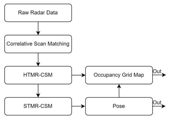
Figure 7.
Millimeter wave radar SLAM based on radar false detections revising algorithm flow chart.
4.1. Hard-Threshold-Multi-Path-Revised Correlative Scan Matching
This paper proposes a new algorithm named the HTMR-CSM algorithm. The HTMR-CSM algorithm is to add the original point cloud data preprocessing module to the original CSM algorithm to filter out all radar false detections. Its threshold is azimuth scattering angle range is 0 or close to 0. The algorithm has no obvious positive effect on positioning error, but its impact on occupancy grid map accuracy is huge. All radar false detections are filtered out on the map. It filters some reliable radar false detections. The density of point clouds is reduced.
The original CSM algorithm is to match two adjacent scans of point clouds, which is a ‘scan-to-scan’ matching way. Each scan has rare points, and the number of points will be less after filtering. Therefore, the original CSM ‘scan-to-scan’ matching method produces errors when performing pose estimation. The more the error accumulates, the greater the error will eventually affect the localization and mapping. In this paper, the HTMR-CSM algorithm uses ‘scan-to-submap’ way to match. This can reduce the pose estimation error and improve the accuracy of localization and mapping.
4.2. Soft-Threshold-Multi-Path-Revised Correlative Scan Matching
HTMR-CSM can filter all radar false detections. However, the filtered points are not all unreliable points. Some of the points are caused by the angular accuracy measurement error of the radar itself. The points with radar measurement errors usually obey a specific distribution, which can improve the accuracy of pose estimation. The other points are radar false detections with structural feature information, whose distribution conforms to the distribution of real target point clouds. Therefore, these points should not be blindly filtered out. They should be used as reliable points to increase the point cloud density.
When millimeter wave radar detects the same target, the detection points are unstable in the radar coordinate system due to the low angular accuracy. It is usually assumed that these points obey the Gaussian distribution shown in Figure 8 [30].
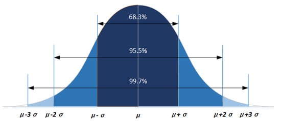
Figure 8.
The probability density of one-dimensional Gaussian distribution.
As shown in Figure 9, the first row is the ideal case. This case assumes that the millimeter wave radar has no angular accuracy error. This situation can accurately estimate the pose. However, the angular accuracy of radar is usually not high. The second row in Figure 9 assumes that the radar detects the same target at different locations. Due to the low accuracy of the radar, the target point is offset in the radar coordinate system. If we do not consider the distribution of angular accuracy, the pose estimation error will be large in the points-matching process. In the third row of Figure 9, the angular accuracy distribution of millimeter wave radar is considered. It can be found that the points at this time will be distributed regularly, which is considered to increase the number and structure of point clouds. In the process of matching, the distributed points will increase the constraint of pose estimation and make pose estimation more accurate.
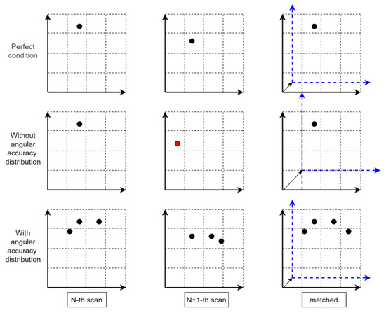
Figure 9.
Point cloud matching diagram.
By analyzing Figure 9, it can be concluded that some radar false detections usually have structural information and conform to the distribution of radar angle measurement accuracy. In the process of matching, they can constrain pose estimation and improve the accuracy of pose estimation. If all the points filtered out by the azimuth scattering angle range are not retained, the point cloud density will be reduced, and some valuable information will be lost. Therefore, this paper analyzes the radar angular accuracy distribution model and uses the model to identify reliable radar false detections. These points increase the point cloud density and reduce pose estimation errors.
This paper improves the HTMR-CSM algorithm. A new algorithm STMR-CSM (Soft-threshold-multi-path-revised correlative scan matching) is proposed. The STMR-CSM algorithm is a method of adding reliable radar false detections recognition based on the HTMR-CSM algorithm. Its threshold conforms to the Gaussian distribution in Figure 8. It can retain reliable radar false detections and reduce positioning and mapping errors.
5. Results and Discussions
5.1. Experimental Equipment
The experimental equipment consists of data acquisition equipment and data processing equipment. The data acquisition equipment is mainly ARS408-21 77 GHz Millimeter Wave Radar. The parameters are shown in Table 1.

Table 1.
77 GHz Millimeter Wave Radar parameters.
5.2. Experiment Result
In this paper, a robot designed by the authors is used to collect millimeter wave radar data from a tunnel. The robot consists of two parts: one is the driving device, and the other is the sensing device. A straight track is installed on the side top of the tunnel, which is parallel to the tunnel. The drive device with the sensor device moves along the rail. The sensor device is equipped with ARS408-21 77 GHz millimeter wave radar. The detection direction of the millimeter wave radar is perpendicular to the movement direction of the robot.
In order to test the strong penetration performance of millimeter wave radar and its ability to penetrate fire and smoke, fire experiments were carried out in the tunnel. The robot moves along the track through the whole fire site to conduct localization and mapping. The fire scene and target scene are shown in the following Figure 10.
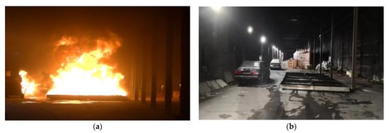
Figure 10.
Experiment scene. (a) Fire smoke experiment. (b) Target scene.
The original point cloud data is processed by the CSM algorithm to obtain the map, as shown in Figure 11.
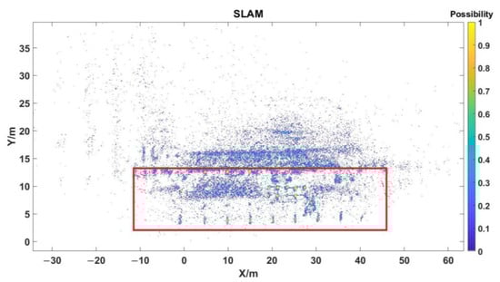
Figure 11.
SLAM grid map with all radar false detections.
We delete all the radar false detections from the original SLAM grid map, as shown in Figure 12a. The existence of radar false detections increases the error of pose estimation, but not all radar false detections will increase the error of pose estimation. Some radar false detections will improve the accuracy of pose estimation. The point cloud matching mode of ‘scan-to-scan’ leads to too large a pose estimation error and cannot perform complete pose estimation. The trajectory is shown in pink in Figure 12b. The point cloud matching mode of scan-to-scan is changed to scan-to-submap, and the trajectory is shown in black in Figure 12b. Then, the HTMR-CSM algorithm and the STMR-CSM algorithm are used to process the point cloud, respectively, and the trajectory is shown in red and blue in Figure 12b.
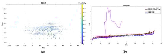
Figure 12.
(a) SLAM grid map with filtered radar false detections. (b) Trajectory comparison.
5.3. Discussion
5.3.1. Grid Map Discussion
The red box in Figure 11 is the real scene of the experiment. Points outside the red box are radar false detections caused by multi-path. The radar false detections of this part are filtered out, and the map is as shown in Figure 12a after filtering. Although the real scene is within the red box in Figure 11, the space closure also produces radar false detections. It can be clearly seen that random and irregular radar false detections appear around the real target pillars, cars, oil pans, etc. The method proposed in Section 3 of this paper is used for filtering all radar false detections. The real targets in Figure 12a are not filtered out, but become clearer and more obvious.
5.3.2. Location Discussion
In addition, this paper also different types of point cloud statistics, as shown in the table. All radar false detections account for 39.28% of all points. According to the method proposed in Section 4.2, reliable radar false detections are identified. It can be found that this part of the point cloud accounts for 30.25% of all points. Filtered points account for only 9.03% of all points.
This section discusses the trajectory of the three methods. The accuracy of pose estimation is evaluated by using three variables: error in the X direction, root mean square error in the Y direction, and root mean square error of rotation angle.
The error in the X direction evaluates the accuracy of the final localization in the X direction, which represents the error between the actual moving distance of the radar and the estimated distance. The calculation formula is shown in (10)
With a straight track as a priori information, the true value of each scan of the radar point cloud in the Y direction and rotation angle can be obtained. Therefore, this paper uses the root mean square error to evaluate the accuracy of pose estimation.
The root-mean-square error in the Y direction evaluates the degree of deviation of the estimated pose from the reference trajectory in the Y direction, calculated as (11).
The root mean square error of rotation angle 1 in each scan evaluates the accuracy of rotation angle estimation and represents the degree of deviation from the reference rotation angle. The calculation formula is shown in (12)
In the formula, represents the scan number, and represents the number of scans of the point cloud. and represent the estimated pose and the real pose in the Y of the -th scan. and represent the estimated pose and the real pose in the rotation of the -th scan.
The error indicators of the three algorithms are counted in the Table 2.
Table 2.
Location Error and Number of Points.
If taking the original CSM without radar false detections suppression as a reference, the localization error and accuracy improvement ratio of HTMR-CSM and STMR-CSM are analyzed. The accuracy of HTMR-CSM on and indicators is significantly reduced, which proves that it is not appropriate to suppress all radar false detections. Radar false detections do not all reduce the accuracy of pose estimation. The accuracy of STMR-CSM is obviously improved in three indicators. It proves that some radar false detections can be utilized, which is beneficial to reduce the pose estimation error and improve the accuracy.
In order to make a more obvious, more intuitive observation of the accuracy of each scan localization, the pose Y and of each scan are analyzed in this paper, as shown in Figure 13. Black represents the original CSM algorithm, red is the HTMR-CSM algorithm, and blue is the STMR-CSM. Although the STMR-CSM algorithm is larger than the CSM algorithm in some scan errors, it is generally small and more stable.
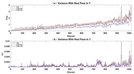
Figure 13.
(a) The variance between the estimated pose of each scan and the real pose in Y. (b) The variance between the estimated pose of each scan and the real pose in .
6. Conclusions
In this paper, the scheme of millimeter wave radar as a sensor for positioning and mapping is successfully applied to the scene of fire and smoke in the tunnel. We find that it is easy to generate multi-path effects in closed spaces such as tunnels, which can affect our positioning and mapping. In this paper, the generation of radar false detections and their influence on positioning and mapping are studied, and the multi-path scattering theory of radar SLAM in tunnel is established. The multi-path scattering theory is of great significance to the identification of multi-path point cloud. Therefore, a multi-path point cloud recognition method based on the target azimuth scattering angle is proposed to filter all radar false detections. An HTMR-CSM algorithm based on scan-to-submap mode is proposed. Although this method effectively removes radar false detections, it does not classify radar false detections. This method ignores that some radar false detections may play a positive role in positioning. The positioning performance of this method decreases, but it can improve the accuracy of mapping. Therefore, point clouds need to be classified to find multi-path point clouds that have a positive impact on pose estimation. This paper combines the reliable radar false detections recognition method with the original CSM algorithm and proposes a new algorithm named STMR-CSM algorithm. The radar data in tunnel is collected by using the equipment developed by the author. Four algorithms are used to process and analyze the data in detail. The experimental results verify that some radar false detections can also be used to improve the accuracy of pose estimation. Compared with the original CSM algorithm, the STMR-CSM algorithm proposed in this paper significantly reduces the positioning error in the closed space, which proves the effectiveness of the method. In the future, we will further study the radar angular accuracy model.
Author Contributions
Conceptualization, Y.L. (Yang Li) and Y.W. (Yanping Wang); methodology, Y.L. (Yang Li); software, Y.W. (Yonghui Wei); validation, Y.W. (Yonghui Wei); formal analysis, Y.W. (Yanping Wang); investigation, Y.W. (Yonghui Wei) and Y.W. (Yanping Wang); resources, Y.W. (Yanping Wang); writing—original draft preparation, Y.W. (Yonghui Wei); writing—review and editing, Y.L. (Yang Li) and Y.W. (Yanping Wang); visualization, Y.L. (Yun Lin); supervision, W.J.; project administration, W.S.; funding acquisition, Y.L. (Yang Li) and Y.W. (Yanping Wang). All authors have read and agreed to the published version of the manuscript.
Funding
This work was supported in part by National Natural Science Foundation of China (grant number: No. 62131001 and No.61971456), by General project of science and technology plan of Beijing Municipal Commission of Education under grant KM202010009011, and by the Yuyou talent training program under grant 218051360020XN115/014.
Acknowledgments
We thank the anonymous reviewers for their good suggestions and comments to help improve the quality of the paper.
Conflicts of Interest
The authors declare no conflict of interest.
References
- Bai, Y.; Liu, G.S.; Zheng, Y.L. Recent Development of Underground Engineering in Shanghai. In Proceedings of the Symposium on Advances in Grounded Technology and Geo-Information/Annual General Meeting of the Geotechnical-Society-of-Singapore, Singapore, 1–2 December 2011; pp. 15–24. [Google Scholar]
- Li, Y.Z.; Ingason, H. Overview of research on fire safety in underground road and railway tunnels. Tunn. Undergr. Space Technol. 2018, 81, 568–589. [Google Scholar] [CrossRef]
- Ntzeremes, P.; Kirytopoulos, K. Applying a stochastic-based approach for developing a quantitative risk assessment method on the fire safety of underground road tunnels. Tunn. Undergr. Space Technol. 2018, 81, 619–631. [Google Scholar] [CrossRef]
- Davison, A.J.; Reid, I.D.; Molton, N.D.; Stasse, O. MonoSLAM: Real-time single camera SLAM. IEEE Trans. Pattern Anal. Mach. Intell. 2007, 29, 1052–1067. [Google Scholar] [CrossRef] [PubMed]
- Huang, L. Review on LiDAR-based SLAM Techniques. In Proceedings of the 2021 International Conference on Signal Processing and Machine Learning (CONF-SPML), Stanford, CA, USA, 14 November 2021; pp. 163–168. [Google Scholar]
- Zhou, T.; Yang, M.; Jiang, K.; Wong, H.; Yang, D. MMW Radar-Based Technologies in Autonomous Driving: A Review. Sensors 2020, 20, 7283. [Google Scholar] [CrossRef] [PubMed]
- Lee, T.J.; Kim, C.H.; Cho, D.I.D. A Monocular Vision Sensor-Based Efficient SLAM Method for Indoor Service Robots. IEEE Trans. Ind. Electron. 2019, 66, 318–328. [Google Scholar] [CrossRef]
- Liang, S.; Cao, Z.Q.; Wang, C.P.; Yu, J.Z. A Novel 3D LiDAR SLAM Based on Directed Geometry Point and Sparse Frame. IEEE Robot. Autom. Lett. 2021, 6, 374–381. [Google Scholar] [CrossRef]
- Dickmann, J. Automotive Radar the Key Technology For Autonomous Driving: From Detection and Ranging to Environmental Understanding. In Proceedings of the 2016 IEEE Radar Conference (RadarConf), Philadelphia, PA, USA, 2–6 May 2016. [Google Scholar]
- Wei, Z.; Zhang, F.; Chang, S.; Liu, Y.; Wu, H.; Feng, Z. MmWave Radar and Vision Fusion for Object Detection in Autonomous Driving: A Review. Sensors 2022, 22, 2542. [Google Scholar] [CrossRef] [PubMed]
- Martin, A.; Ebi, J.; Ba-Ngu, V. Robotic Navigation and Mapping with Radar; Artech: Morristown, NJ, USA, 2012. [Google Scholar]
- Besl, P.J.; McKay, N.D. A method for registration of 3-D shapes. IEEE Trans. Pattern Anal. Mach. Intell. 1992, 14, 239–256. [Google Scholar] [CrossRef]
- Censi, A. An ICP variant using a point-to-line metric. In Proceedings of the IEEE International Conference on Robotics and Automation, Pasadena, CA, USA, 19–23 May 2008; pp. 19–25. [Google Scholar]
- Ji, Z.; Singh, S. LOAM: Lidar Odometry and Mapping in Real-time. In Proceedings of the Robotics: Science and Systems Conference, Berkeley, CA, USA, 12–16 July 2014. [Google Scholar]
- Lin, J.; Zhang, F. Loam livox: A fast, robust, high-precision LiDAR odometry and mapping package for LiDARs of small FoV. In Proceedings of the 2020 IEEE International Conference on Robotics and Automation (ICRA), 31 May–31 August 2020; pp. 3126–3131. [Google Scholar]
- Shan, T.; Englot, B. LeGO-LOAM: Lightweight and Ground-Optimized Lidar Odometry and Mapping on Variable Terrain. In Proceedings of the 2018 IEEE/RSJ International Conference on Intelligent Robots and Systems (IROS), 1–5 October 2018; pp. 4758–4765. [Google Scholar]
- Olson, E.B. Real-time correlative scan matching. In Proceedings of the IEEE International Conference on Robotics & Automation, Kobe, Japan, 12–17 May 2009. [Google Scholar]
- Witrisal, K.; Meissner, P.; Leitinger, E.; Shen, Y.; Gustafson, C.; Tufvesson, F.; Haneda, K.; Dardari, D.; Molisch, A.F.; Conti, A.; et al. High-Accuracy Localization for Assisted Living: 5G systems will turn multipath channels from foe to friend. IEEE Signal Process. Mag. 2016, 33, 59–70. [Google Scholar] [CrossRef]
- Guo, X.P.; Du, J.S.; Gao, J.; Wang, W. Pedestrian Detection Based on Fusion of Millimeter Wave Radar and Vision. In Proceedings of the 2018 International Conference, Beijing, China, 18–20 August 2018. [Google Scholar]
- Kellner, D.; Klappstein, J.; Dietmayer, K. Grid-based DBSCAN for clustering extended objects in radar data. In Proceedings of the Intelligent Vehicles Symposium, Madrid, Spain, 3–7 June 2012; pp. 365–370. [Google Scholar]
- Li, Y.; Liu, Y.; Wang, Y.; Lin, Y.; Shen, W.J. The Millimeter-Wave Radar SLAM Assisted by the RCS Feature of the Target and IMU. Sensors 2020, 20, 5421. [Google Scholar] [CrossRef] [PubMed]
- Sander, J.; Ester, M.; Kriegel, H.P.; Xu, X.J.D.M.; Discovery, K. Density-Based Clustering in Spatial Databases: The Algorithm GDBSCAN and Its Applications. Data Min. Knowl. Discov. 1998, 2, 169–194. [Google Scholar] [CrossRef]
- Ge, Y.; Wen, F.X.; Kim, H.; Zhu, M.F.; Jiang, F.; Kim, S.; Svensson, L.; Wymeersch, H. 5G SLAM Using the Clustering and Assignment Approach with Diffuse Multipath. Sensors 2020, 20, 31. [Google Scholar] [CrossRef] [PubMed]
- Kimura, H.; Papathanassiou, K.P.; Hajnsek, I. Polarization orientation effects in urban areas on sar data. In Proceedings of the 2005 IEEE International Geoscience and Remote Sensing Symposium, 2005. IGARSS ‘05, Seoul, Republic of Korea, 29 July 2005; Volume 7, pp. 4863–4867. [Google Scholar]
- Etinger, A.; Litvak, B.; Pinhasi, Y. Multi Ray Model for Near-Ground Millimeter Wave Radar. Sensors 2017, 17, 1983. [Google Scholar] [CrossRef] [PubMed]
- Guo, J.; Jin, M.; He, Y.; Wang, W.; Liu, Y. Dancing Waltz with Ghosts: Measuring Sub-mm-Level 2D Rotor Orbit with a Single mmWave Radar. In Proceedings of the IPSN ‘21: The 20th International Conference on Information Processing in Sensor Networks, Nashville, TN, USA, 18–21 May 2021. [Google Scholar]
- Hao, Z.J.; Yan, H.; Dang, X.C.; Ma, Z.Y.; Jin, P.; Ke, W.Z. Millimeter-Wave Radar Localization Using Indoor Multipath Effect. Sensors 2022, 22, 18. [Google Scholar] [CrossRef] [PubMed]
- Leigsnering, M.; Ahmad, F.; Amin, M.G.; Zoubir, A.M. Compressive Sensing-Based Multipath Exploitation for Stationary and Moving Indoor Target Localization. IEEE J. Sel. Top. Signal Process. 2015, 9, 1469–1483. [Google Scholar] [CrossRef]
- Roos, F.; Sadeghi, M.; Bechter, J.; Appenrodt, N.; Dickmann, J.; Waldschmidt, C. Ghost Target Identification by Analysis of the Doppler Distribution in Automotive Scenarios. In Proceedings of the 18th International Radar Symposium (IRS), Prague, Czech Republic, 28–30 June 2017. [Google Scholar]
- Paredes, J.A.; Alvarez, F.J.; Hansard, M.; Rajab, K.Z. A Gaussian Process model for UAV localization using millimetre wave radar. Expert Syst. Appl. 2021, 185, 13. [Google Scholar] [CrossRef]
Disclaimer/Publisher’s Note: The statements, opinions and data contained in all publications are solely those of the individual author(s) and contributor(s) and not of MDPI and/or the editor(s). MDPI and/or the editor(s) disclaim responsibility for any injury to people or property resulting from any ideas, methods, instructions or products referred to in the content. |
© 2023 by the authors. Licensee MDPI, Basel, Switzerland. This article is an open access article distributed under the terms and conditions of the Creative Commons Attribution (CC BY) license (https://creativecommons.org/licenses/by/4.0/).