Article

BDD-Net: An End-to-End Multiscale Residual CNN for Earthquake-Induced Building Damage Detection

1
Department of Photogrammetry and Remote Sensing, School of Surveying and Geospatial Engineering, University of Tehran, Tehran 14174-66191, Iran
2
RIKEN Center of Advanced Intelligence Project, Disaster Resilience Science Team, Tokyo 103-0027, Japan
3
Department of Multimedia, Faculty of Computer Science and Information Technology, Universiti Putra Malaysia, Serdang 43400, Malaysia
*
Author to whom correspondence should be addressed.
Remote Sens. 2022, 14(9), 2214; https://doi.org/10.3390/rs14092214
Submission received: 14 March 2022 / Revised: 29 April 2022 / Accepted: 1 May 2022 / Published: 5 May 2022
(This article belongs to the Special Issue Intelligent Damage Assessment Systems Using Remote Sensing Data)

Abstract

:
Building damage maps can be generated from either optical or Light Detection and Ranging (Lidar) datasets. In the wake of a disaster such as an earthquake, a timely and detailed map is a critical reference for disaster teams in order to plan and perform rescue and evacuation missions. Recent studies have shown that, instead of being used individually, optical and Lidar data can potentially be fused to obtain greater detail. In this study, we explore this fusion potential, which incorporates deep learning. The overall framework involves a novel End-to-End convolutional neural network (CNN) that performs building damage detection. Specifically, our building damage detection network (BDD-Net) utilizes three deep feature streams (through a multi-scale residual depth-wise convolution block) that are fused at different levels of the network. This is unlike other fusion networks that only perform fusion at the first and the last levels. The performance of BDD-Net is evaluated under three different phases, using optical and Lidar datasets for the 2010 Haiti Earthquake. The three main phases are: (1) data preprocessing and building footprint extraction based on building vector maps, (2) sample data preparation and data augmentation, and (3) model optimization and building damage map generation. The results of building damage detection in two scenarios show that fusing the optical and Lidar datasets significantly improves building damage map generation, with an overall accuracy (OA) greater than 88%.

1. Introduction

The Earth is always under threat by natural disasters such as wildfires, floods, and earthquakes. These disasters can cause a lot of damage in their wakes, which could cross regions. Earthquakes are a natural disaster that has the most impact on human settlements, particularly in urban areas [1]. Therefore, monitoring and assessing damage levels is vital in urban areas in order to understand this type of disaster [2].
Buildings make up a large portion of urban areas, and it is crucial that damaged buildings be properly indicated after earthquakes [3]. In past decades, remote sensing played a key role in providing wide coverage surface data at minimal cost and time. Due to this, RS data is used in many applications such as change detection [4], forest monitoring [5], soil monitoring [6], and crop mapping [7]. Another important application is damage detection and assessment, which makes use of RS datasets such as Light Detection and Ranging (Lidar) [8], nightlights datasets [9], multispectral datasets, Synthetic Aperture Radar (SAR) [3,10], and optical very high-resolution imagery [2,11]. Although these data types can be used for damage assessment, they have limitations:
  • SAR imagery has high backscatter in built-up areas and suffers from low temporal and spatial resolution. Furthermore, it is difficult to interpret and detect similar objects.
  • Nightlights data are deployed in rapid damage assessment scenarios. They suffer, however, from low spatial resolution. Furthermore, nightlight can be affected by external factors that increase the potential for false alarms and missing detections.
  • Multispectral data have high spectral and temporal resolutions that can help detect damaged areas. Such datasets are also of low spatial resolution, which makes damage detection for individual buildings difficult.
  • Optical VHR (very high resolution) data form the most common type of dataset for building damage detection that facilitates interpreting and processing damaged areas. One of the common issues with this kind of data is that only the roofs of damaged buildings can be detected. Shadows are also said to affect assessment results.
  • Lidar data are utilized widely in building damage assessment. The major limitation of these data is that they are difficult to interpret.
It is worth noting that optical and Lidar data have their own strengths (and weaknesses) in different scenarios. This is summarized in Figure 1, where detection capabilities of each dataset depend on the type of detection required. We foresee that fusing both types of dataset can potentially mitigate the limitations of each. Hence, this research explores the advantages of fusing optical VHR RS and Lidar datasets for mapping building damages.
According to [12], fusion can take place at three levels: (1) the pixel-level, (2) the feature-level, and (3) the decision-level. In the literature, feature- and decision-level fusion are more commonly utilized for damage assessment [13].
As the name implies, pixel-level fusion combines/integrates both datasets at the pixel-level, which is known as pansharpening. The gist is to enhance the spatial resolution of the low-resolution dataset by combining the panchromatic dataset into a low spatial resolution dataset. This process can be applied using either linear or non-linear transformation-based methods.
Feature-level fusion is widely used in classification, damage assessment, or change detection tasks. At this level, some type of feature is extracted from each modality, and then both are ‘stacked’ to form the final representation. The more popular features used in RS work are: (1) spatial features, including texture features such as the Gray-level Co-occurrence Matrix (GLCM) [14] and the Gabor filter Gabor transformation [15], as well as morphological attribute profiles (MAP) [16]; (2) spectral features obtained through linear and non-linear transformations, such as Principle Component Analysis (PCA), the Normalized Vegetation Index (NDVI), and (3) deep features, which are obtained through Convolutional Neural Networks (CNN).
Decision-level fusion takes place when the results from more than one learning algorithm are fused [12,17]. Two types of fusion exist: (1) hard fusion, where the final classification result is determined through hard label majority voting, Borda count, and Bayesian fusion [18]; and (2) soft fusion, where the final decision is based on the probability of obtaining results ( p -value), with many methods proposed for this end, such as fuzzy-fusion [19] or Dempster-Shafer (DS) fusion [20]. Since decision-level fusion requires the results of various classifiers and possibly from multisource datasets, it can be time-consuming. Furthermore, at least two classifiers need to be tuned, as well as the parameters of the fusion algorithm.
Among the types of fusion methods, feature-level fusion can be more compatible with Lidar and optical datasets. The feature-level fusion strategy has low complexity in comparison to decision-level fusion. One of the disadvantages of traditional feature-level fusion algorithms is the extraction of suitable features. Mainly, the building damage mapping based on traditional feature-level fusion algorithms requires informative feature generation and then feature selection, which is a time-consuming process. To this end, this research utilizes the advantages of feature-level fusion for generating building damage maps. The main purpose of this research is to take advantage of both Lidar and optical datasets for earthquake-induced building damage maps in order to minimize the above-mentioned challenges. Thus, a multi-stream deep feature extractor method based on the CNN algorithm is proposed for building damage mapping using the post-earthquake fused Lidar and optical data. In the proposed method, the extracted deep features for buildings are integrated through a fusion strategy and imported into a Multilayer Perceptron (MLP) classifier to make the final decision to detect damaged buildings.
The wide availability of RS datasets has led to the proposal of several damage assessment methods and frameworks. For building damage mapping, the most common datasets include SAR, Optical VHR, nightlight, Lidar, and multispectral datasets. For instance, Adriano et al. [21] proposed a building damage multimodal detection framework by combining SAR, optical, and multi-temporal datasets. U-Net architecture was used with two branches to detect building damages. In the encoder phase of the architecture, they used the optical and SAR datasets. The extracted deep features were fused at the pixel-level and used in the decoder phase to generate the damage map. Additionally, Gokaraju et al. [22] proposed a change detection framework for disaster damage assessment based on multi-sensor data fusion. This study utilized an SAR dataset and multispectral and panchromatic datasets. Specifically, several features such as multi-polarized radiometric and textural features were extracted, then multi-variate conditional copula were utilized for binary classification to generate binary damage mapping. In another work based on change detection, Trinder and Salah [23] fused bi-temporal aerial and Lidar datasets. They basically performed change detection using methods such as post-classification, image differencing, PCA, and minimum noise fraction. In the end, a simple majority vote was used for damage map generation. Finally, Hajeb et al. [24] proposed a damage building assessment framework based on integrating post/pre-earthquake Lidar and SAR datasets. They firstly performed texture feature extraction on the Lidar dataset, and then change was detected on the original Lidar datasets and extracted features. A coherence map was later generated followed by coherence change detection on SAR datasets. Finally, the damage map was generated through an RF- and Support Vector Machine (SVM)-supervised classification.
The work in this paper is proposed based on the following motivations:
(1)
Most of the previous works had the researchers determine the relevant features manually.
(2)
Decision-level fusion methods can be difficult to implement and requires many considerations. Additionally, the source data need to be classified at separate levels, and then the results are only fused at the end. This might potentially lead to incorrect initial classification, which in the end compromises the whole assessment task.
(3)
Most previous frameworks employ “traditional” machine learning methods. However, the performance of deep learning methods has been proven by many studies.
(4)
Most feature-level fusion methods are applied in many steps and this is time-consuming.
(5)
Most feature-level fusion methods are based on pre/post-event images, but it is difficult to obtain post-event imagery. Furthermore, multi-source datasets have improved the performance of classification and damage detection significantly.
(6)
Change detection-based damage assessment has shown promising results, but removing the effect of non-target changes (atmospheric condition, manufactured changes) is the most challenging aspect. To this end, it is necessary to propose a novel algorithm to minimize these challenges and improve the result of building damage detection.
Based on the reviewed studies, multi-source data can be integrated and used for building damage mapping. Among different data sources, SAR imagery has many advantages, such as operation in all weather conditions, and penetrating through clouds and rain. However, it suffers from noise, can be difficult to interpret, and have low spatial and spectral resolutions. Based on Figure 1, optical and Lidar are shown to be complementary datasets for evaluating the damage to a building. Therefore, the fusion of these datasets can seemingly improve the accuracy and quality of the resulting damage maps (provided a suitable fusion strategy is employed). Choosing a suitable fusion strategy depends on several factors, which will be explained in the next section.
This research proposes a new framework for building damage detection based on deep learning. The proposed network, termed BBD-Net, is an end-to-end framework for damage assessment. There is a total of three channels: two channels to extract deep features from the optical and Lidar datasets, and the third channel is the fusion channel that fuses the extracted deep features from the first and second channels. The main contribution of this research is to: (1) present the novel end-to-end fusion framework for building damage assessment by deep learning methods, (2) propose a framework that takes advantage of residual multi-scale dilated kernel convolution and of depth-wise kernel coevolution, and (3) evaluate the performance for each dataset and perform comparisons with BDD-Net.

2. Materials and Methods

2.1. Study Area and Image Acquisition

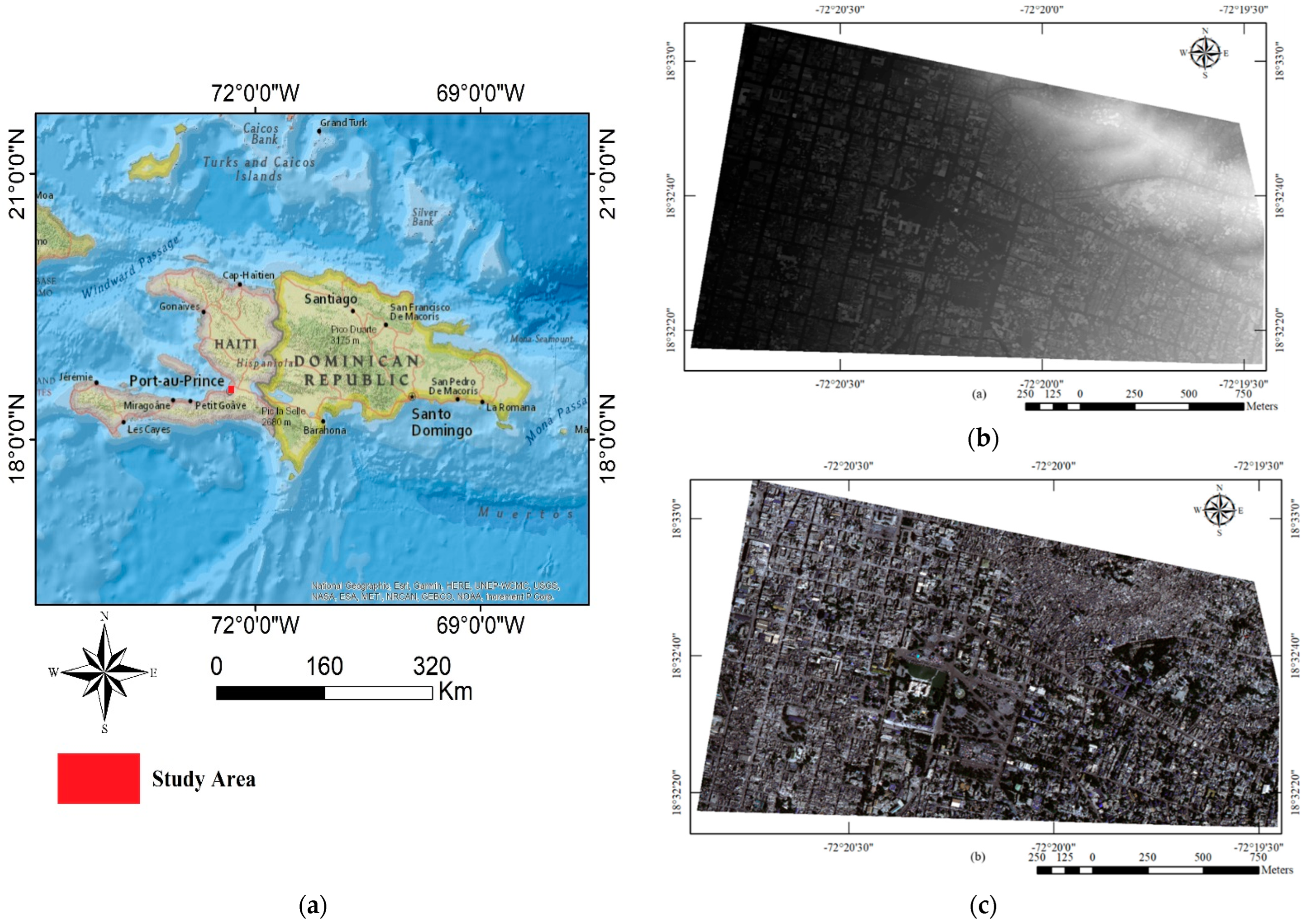
On 12 January 2010, at 4:53 p.m. local time, a magnitude 7.0 earthquake struck the Republic of Haiti, with an epicenter located approximately 25 km south and west of the capital city of Port-au-Prince (Figure 2a). According to the Government of Haiti, the earthquake left more than 316,000 dead or missing; 300,000 injured; and over 1.3 million homeless [25]. The post-earthquake optical RS data and aerial Lidar data of Port-au-Prince, Haiti were used. The optical VHR dataset (Figure 2c) was captured by the World-View-II sensor with 4 spectral bands (Red, Green, Blue, and NIR-Infrared) on 16 January 2010 with a spatial resolution of 0.5 m. The Lidar dataset(Figure 2b) was collected between 21 January and 27 January 2010 with a spatial resolution of 1 m. Since the extracted bounding box of the buildings is used as the input patch, only removing debris from a damaged building may cause a mismatch between the datasets. However, due to the short temporal difference between the two datasets (around a week or 10 days), the high impact of the earthquake on a large number of buildings, and the low resolution of the datasets concerning possible debris removal, all the mismatches inside the building areas were ignored.

2.2. Ground Truth Data

In this research, the sample data was manually collected and divided into two classes: (1) Damage and (2) Non-damage. This sample was used to train BDD-Net. The dataset consists of 603 polygons; where 301 are from the Damaged class, and 302 polygons are from the Intact class. The dataset is further divided into three parts: (1) Training (54%), Validation (10%), and Testing (36%). Table 1 presents some samples for two Damage and Non-damage classes.
Table 2 presents the detailed description of random samples for both the Damage and Non-damage classes. As can be seen, in some cases, the situation may not be detected based on only one dataset.
Within this dataset, some buildings were employed for training and evaluation of the proposed BDD-Net. The selected test area is 945 × 542 m2, which is illustrated in Figure 3. The vector road maps were obtained from OSM, and the building vector map was created manually based on visual analysis of the pre-event dataset.
As mentioned, the sample collected is crucial in order to train our supervised learning algorithm [26]. The quality and quantity of training data play a key role in classification results. One of the critically important evaluations of classifier methods is generalization. For evaluating generalization, this research used two different regions for training and evaluating the network. Figure 3 illustrates the distribution of sample data (red and green) for two classes of Damage and Non-damage polygons. The yellow polygons were utilized for evaluating the proposed BDD-Net.

2.3. Methodology Applied

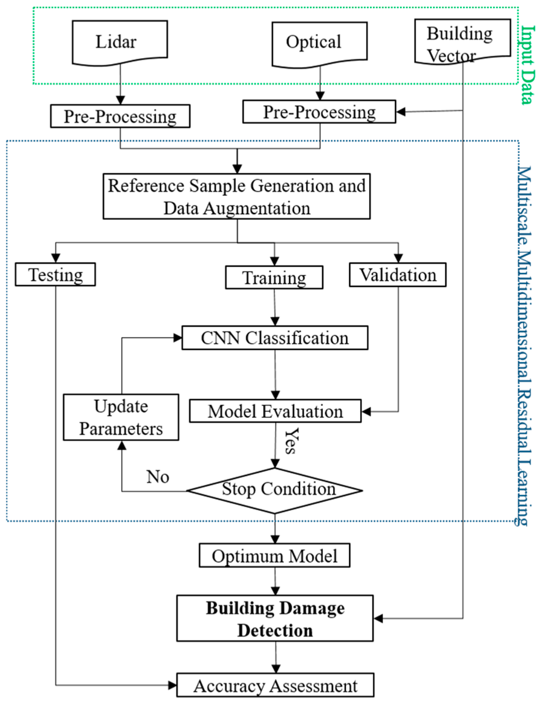
The flowchart of the BDD-Net for building damage mapping is illustrated in Figure 4. BDD-Net consists of three main parts: (1) pre-processing, (2) training sample generation and data augmentation, and (3) the training of CNN and building damage map generation.

2.3.1. Image Pre-Processing

Images might contain some form of noise or unwanted visual properties. Therefore, this step ensures the images fed into BDD-Net contain the least amount of irrelevant information. Specifically, atmospheric correction and histogram equalization of the image was performed. The image and its respective vector map was also accurately registered. This research utilized the building vector map layer that is obtained by OSM. It is worth noting that this vector layer needed to be registered with our datasets. The vector dataset (building footprint) can be seen in Figure 3 as yellow, red, and green regions.

2.3.2. Data Augmentation

Due to a lack of training examples, most deep learning methods employ data augmentation [27], which helps to artificially increase the number of training and validation sets. In this work, the types of augmentation we applied were a combination of the following (Table 3):
  • Rotation (25°, 35°, 75°, 85°, 120°, 145°, 225°, 265°, 295°, 310° and 330°);
  • Brightness adjustment by a scale of 0.01; and
  • Zooming.

2.3.3. Proposed Method

BDD-Net consists of three channels for deep feature extraction. The first channel extracts deep features from the optical dataset. The second channel extracts deep features from the original Lidar dataset. The third channel is the channel that fuses all deep features from the first and second channels. Figure 5 presents the proposed architecture for our building damage detection framework. As can be seen, three deep feature extractor channels are included in five multi-scale/residual convolution layers with three pooling layers to reduce the features’ spatial size. Then, a depth-wise convolution generates the deep features. Finally, all deep features are concatenated and fed to a fully connected layer. The main differences between the proposed architecture and other deep-learning-based damage detection methods are (1) that the proposed multi-stream deep feature extractor extracts from both Lidar and optical datasets (and fuses them), (2) that the feature fusion level is applied to different levels (low and high levels) to improve the efficiency of damage mapping, and (3) takes advantage of the depth-wise convolution for damage mapping of the multiscale residual kernel convolution layers, which has better performance against scale variations and decreases the number of network parameters that help to prevent gradient vanishing.
The main task of the convolution layers is to extract high-level deep features from the input images [28,29,30]. For a convolutional layer in the l -th layer, the computation is expressed according to Equation (1) [31]
  y l = g ( w l x l 1 ) + b l
where x is the input from layer l 1 ; g is the activation function; w is the weighted template; and b is the bias vector.
In the 2D convolution layer, the output of the j -th feature map f in the i -th layer at the spatial location ( x , y ) can be computed using Equation (2) [32]
f i , j x y = g ( b i , j + m   r = 0 R i 1   s = 0 S i 1   W i , j r , s f i 1 , m ( x + r ) ( y + s ) )
where m is the feature cube connected to the current feature cube in the ( i 1 ) -th layer; W is the ( r ,   s ) -th value of the kernel connected to the m -th feature cube in the preceding layer; and R and S are the length and width of the convolution kernel size, respectively.
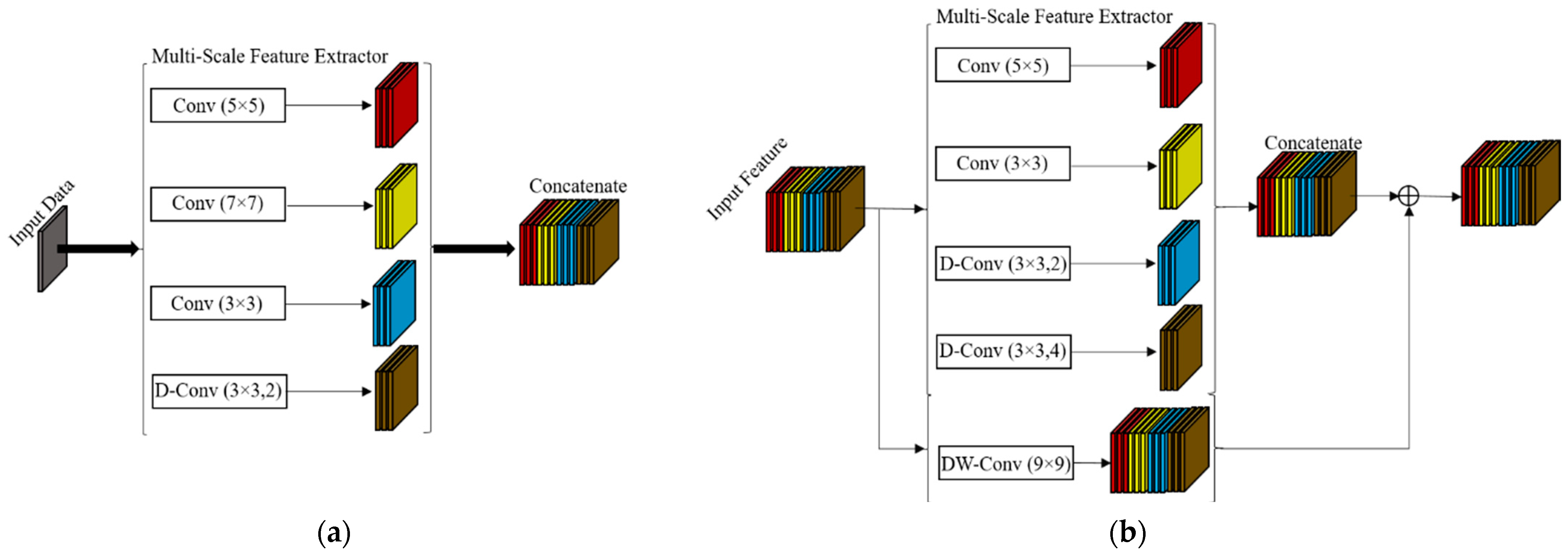
This work utilized three different scenarios for deep feature extraction. Figure 6 shows the different strategies for deep feature extraction.
As shown in Figure 6, the proposed method combines several strategies for deep feature extraction. The intuition behind each are explained in the following:
(1)
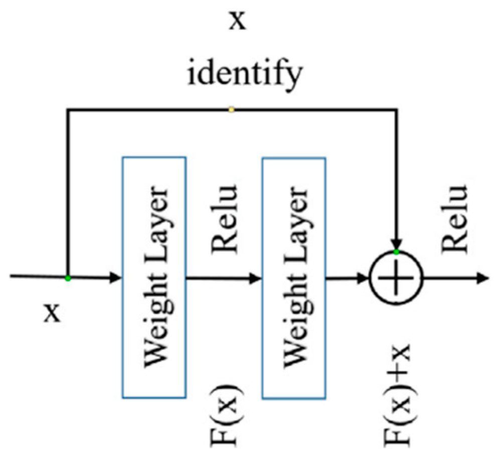
Residual blocks: These blocks allow the gradient to be directly back-propagated to earlier layers, which is especially useful for avoiding the problem of the vanishing or exploding gradient [33]. A graphical representation for this is shown in Figure 7.
(2)
Multi-scale blocks: The size of buildings on the ground will be affected after an earthquake. Multi-scale blocks, as explained in [34,35], increase the robustness of the network against scale variations. The multi-scale block utilizes some of the 2D-standard convolution layers, while the kernel filter sizes are different.
(3)
Dilated convolution: This improves the network’s performance by creating a larger receptive field while preserving the same computation and memory costs as well as resolution [36,37]. Mathematically, the 2D-dilated convolution can be defined based on the following (Equation (3)) [38]
f i , j x y = g ( b i , j + m   r = 0 R i 1   s = 0 S i 1   W i , j r , s f i 1 , m ( x + r × d ) ( y + s × d ) )
where d is the dilatation rate in the convolution layer. Figure 8 illustrates the mechanism of dilated convolution at different rates.
(4)
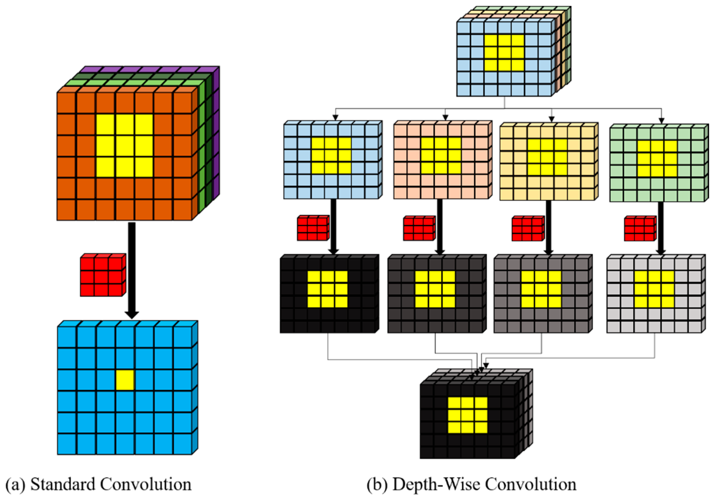
Depth-wise convolution helps to prevent the growth of the network and the reduction of parameters [39]. Basically, two steps are involved: (1) A 2D convolution is performed for each input feature (channel) to generate a 2D output feature map; then (2) the output feature maps are concatenated to complete the output tensor. Figure 9 shows the main difference between depth-wise convolution and standard convolution blocks graphically.

2.3.4. Fusion Strategy

All deep features for feature-level fusion are assigned to a stream. This stream combines extracted deep features by convolution layers from Lidar and optical datasets. At first, the extracted shallow deep features (from Lidar and Optic) from the first convolution layers are transferred to the fusion stream as the input. These features are concatenated and fed to a convolution layer in the fusion channel. Then, the output of the mentioned convolution layer and outputs of second layers from optic and Lidar are stacked and are investigated as input for the second convolution layer in the fusion channel. This process is repeated for other convolution layers.

2.3.5. Model Optimization

Several hyperparameters need to be set before training any deep learning model. In this work, the optimization algorithm used is the Adam (Adaptive Moment Estimation) optimizer. The performance of the training at each epoch is evaluated by a loss function. Once the error is calculated, this it is adjusted in the whole network by Adam and all weights are updated in a backpropagated manner. We have opted to use the Tversky loss function, which is a generalization of the Dice score [40,41]. The Tversky index (TI) between P (predicted-value) and G (truth-value) is defined as (Equation (4)) [40,41]
T I ( P , G , α , β ) = | P G | | P G | + α | P G | + β | G P |
where α and β control the magnitude of penalties for false-positive and false-negative pixels, respectively.
The overall training and validation process for BDD-Net is iterative, depending on the number of epochs. It will keep learning until a stop condition is met, which in this case can either be (1) the number of epochs, or (2) deviating from the error on the validation set.

2.3.6. Evaluating the Performance Metrics

One of the most important aspects is the assessment of the accuracy of results in two parts: (1) accuracy assessment based on visual analysis (inspection) and comparison of the result with reference data, and (2) accuracy assessment based on quality measurement indices. This work deployed 5 of the most common assessment indices, including overall accuracy, Recall, F1 Score, and Matthews Correlation Coefficient (MCC). More details of these indices can be found in Table 4 and Table 5.

3. Results

3.1. Hyperparameter Setting

BDD-Net hyperparameters were set manually based on trial and error. The optimum values for these parameters are as follows: the input patch-size for Lidar and optical data is 50 × 50 × 1 , and 50 × 50 × 4 , respectively; the number of Epochs = 2000 ; the weight initializer is the Xavier initialization method [42], the number of neurons at the fully-connected (FC) layer is 1500 ; the initial learning rate is 10 4 ; and the mini-batch size = 550 .

3.2. Overall Performance

Three scenarios were considered and observed in this research. The first scenario is building damage detection based on only the Lidar dataset. The second scenario is the use of only the optical dataset, and the third scenario is using the fusion of optical and Lidar datasets. The results of building damage assessment are evaluated in two parts (sample data and test area).
The overall dataset is divided into three parts and the model optimization was conducted based on the training and validation datasets. A separate testing dataset was utilized for evaluating the model. The performance of the prosed BDM network was evaluated based on 3,615 sample data points. The results of BDD are presented in Table 6.
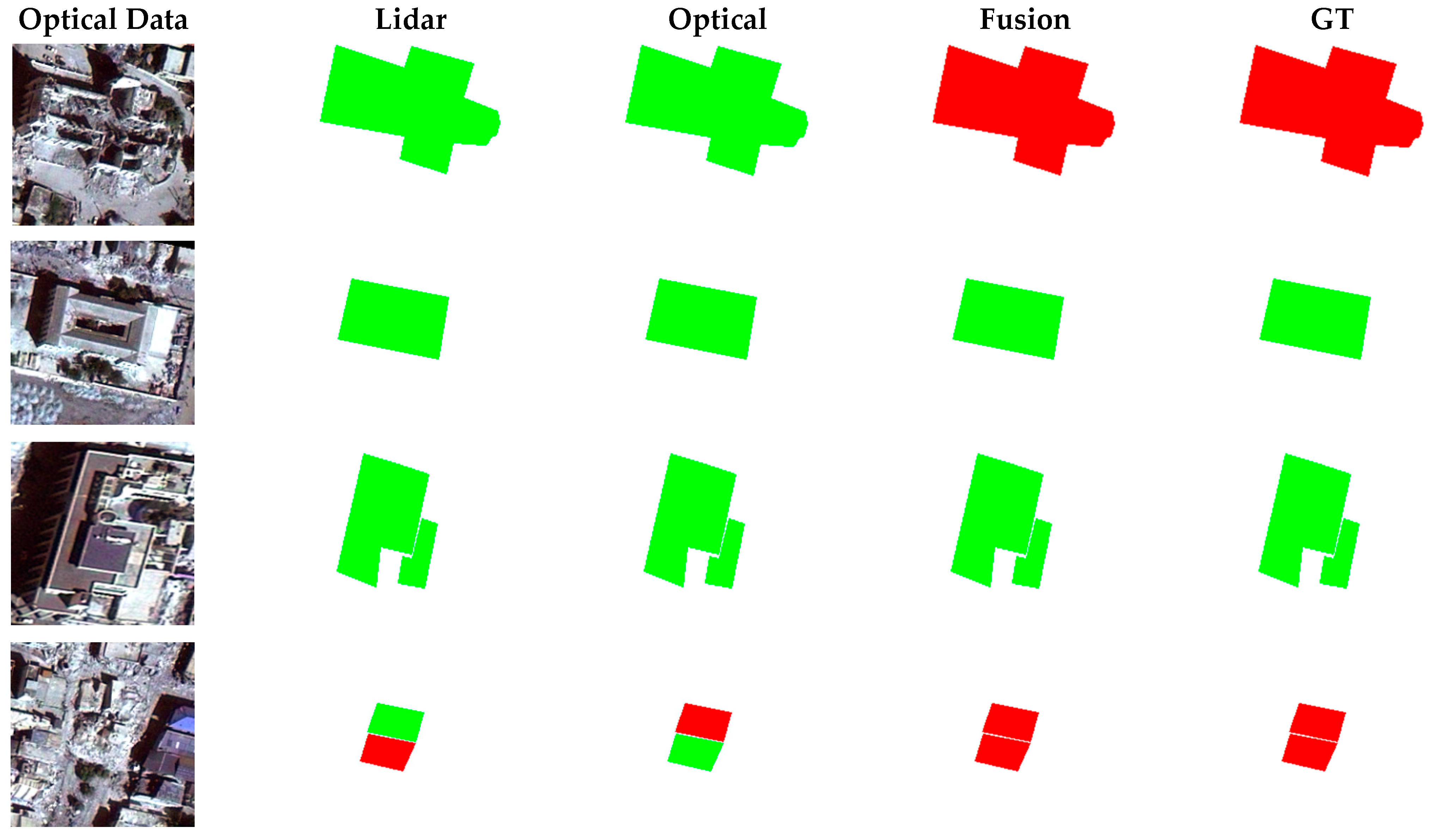
As can be seen, the BDD-Net shows good performance for all three datasets. The fusion approach however, is clearly the best, with the highest scores for all metrics. When only using Lidar or optical, the FP pixels dominate the FN pixels, while for the fusion approach, the FN pixels have the upper hand over FP pixels. The MCC and F1-Score are more important indices both TN and TP pixels were used. Additionally, the BDD-Net provided high values of MCC and F1-scores that reflect the BDD-Net’s ability to detect damaged buildings and non-damaged buildings as well. Figure 10 shows the visual results of building damage detection for the test areas. The results also indicate a good performance of BDD-Net. Figure 10b presents the result of damage detection by the optical dataset. The performance of BDD-Net in the detection of damaged buildings in the Lidar dataset and fusion scenario (Figure 10a,c) seems better than when only considering the optical dataset. There are some damaged buildings classified as intact buildings based on the optical dataset. The fusion scenario provided the best performance in the detection of non-damaged and damaged buildings.
The numerical results of building damage detection are presented in Table 7. BDD-Net correctly detected 43, 15, and 55 damaged buildings from 104 damaged buildings based on Lidar, optical, and fusion scenarios, respectively. Among the 422 intact buildings, 375, 411, and 409 buildings were classified correctly by BDD-Net by deploying Lidar, optical, and fusion, respectively. Generally, the BDD-Net using the fused dataset shows the best performance. However, there is little difference in the detection of the non-damaged buildings with the optical dataset and the fusion scenario (two building polygons), but the optical scenario shows a significant difference for damaged buildings.
Overall, the accuracy of BDD-Net for the test area is promising at 88.21%. The fusion approach seems to outshine the single-modality approaches once again, confirming its effectiveness. For all the other metrics, fusion was also better than the others. The MCC is the most important measurement when assessing imbalanced datasets. The score obtained for the fusion approach is 0.591, which indicates a good potential for overall building damage classification.

3.3. Comparison with Other State-of-the-Art Methods

Recently, damage detection using multi-source data fusion has become a challenging topic, and many research studies have been conducted for damage assessment in Haiti or other earthquakes. Table 8 presents three sample damage detection methods based on multi-source datasets for the same case study. Based on the presented results, many methods have shown promise using some form of fusion strategy for building damage mapping. We have compared BDD-Net with selected state-of-the-art fusion methods, and accuracy was highest for BDD-Net. It should be noted that the case study is the same for all methods, but different areas may have been selected from the whole area. Overall, as indicated by the other methods compared in Table 8, the fusion strategy seems to be very promising for damage detection.
Many research studies have utilized change detection algorithms and compared pre- and post-event images for damage map creation. For example, Refs. [44,45,46] used the WorldView 2 images acquired before and after the Haiti earthquake and reported various accuracies ranging from 60 to 87%. Another case [44], which is a deep learning-based CNN method, has provided an accuracy almost similar to the BDD-Net algorithm.

4. Discussion

4.1. Summary of Performance of BDD-Net in Different Scenarios

We have considered the problem of building damage detection (BDD) by taking a single-modality approach (either using optical or Lidar data), or a fusion approach where both modalities are considered simultaneously. As per the results in Table 6 and Table 7, as well as the visual results in Figure 10, single or fused modalities managed to produce accuracy of over 80%. However, the highest accuracy, even in the test area, was achieved through the fusion strategy. Also reflecting the effectiveness of fusion using BDD-Net is the MCC, which is higher than 0.6. The justification for using the fusion strategy is further strengthened by the fact that BDD-Net fails to detect damaged buildings when using optical alone (but is able to detect non-damaged buildings).

4.2. Sample Data and Training Process

Training a supervised deep learning model normally requires huge amounts of quality sample data to enable the model to optimally converge [47,48]. However, collecting and labelling huge data samples can be time-consuming and labor intensive. Therefore, our approach makes use of data augmentation, which is a process that adds artificial samples to the training data via specific geometric transformations. In all, this utilized only 603 polygons for the training model; this size of sample data is considerably low.
Recently, some state-of-the-art methods based on semantic segmentation were utilized for damage detection purposes. For example, Gupta and Shah [49] have proposed a building damage assessment framework (Rescuenet) based on pre/post-event optical high-resolution datasets. These methods provided promising results in the damage generation map, but they require too large a sample dataset for the training model. Collecting a high amount of reference sample data for such a problem is very difficult. Furthermore, the training of the semantic segmentation models such as deeplabv3+ [50], U-Net++ [51], and Rethinking BiSeNet [52] requires more time. Additionally, these frameworks need advanced processing tools for training the model and an optimization of hyperparameters. Thus, BDD for small areas based on semantic segmentation methods is not affordable, since the training process of the proposed BDD-Net takes under 4 h, while the semantic segmentation methods require more time.

4.3. Generalization of BDD-Net

This research evaluated the performance of BDD-Net in two scenarios: (1) evaluation of sample date, (2) test areas. The buildings of the test area do not contribute to the training of the model. The structure of buildings in test areas and collected sample areas differ in some building parameters (size, color, and elevation). Figure 11 shows some sample buildings that considerably differ in comparison to buildings in the sample data.
Based on numerical and visual analysis, BDD-Net manages to perform well even for the test areas. A fusion of optical and Lidar seems to be the best strategy, where a high OA of more than 88% was reported. The good performance of BDD-Net on the test might be a good indication that it will be able to generalize well on unseen data.

4.4. Feature Extraction

Feature- and decision-level fusions are the most common strategies when dealing with multi-source remote sensing imagery. The BDD-Net framework is applied end-to-end and generates deep features form three feature extractor channels. The BDD-Net can extract deep features from both the Lidar and optical modalities, in addition to the third channel focused on integrating expected features to obtain more details.
The proposed BDD-Net employs hybrid robust deep-feature extractor convolution layers based on dilated convolution, residual block, depth-wise convolution, and multi-scale convolution layers. This advantage of the proposed method enables BDD-Net to produce good results in damage map generation. Furthermore, the BDD-Net automatically extracts and select the deep features by changing the hyperparameters, while many researchers have used traditional features such as textural features based on the GLCM matrix [53,54,55,56], or morphological attribute profiles [57], which are time-consuming, and the optimal features are selected manually.

4.5. Fundamental Error

One of the most important challenges of classification based on multi-source imagery is registration error. For instance, change detection-based methods require accurate registration. This is difficult to achieve since control points for matching are not easily discoverable due to the content of data and the difference between resolutions. This can lead to a cascade of issues as changes originating from the registration error can trickle down to the pixel-based damage detection. BDD-Net can control this issue, and minimize the registration error, by considering the building polygon in the decision making.
The height relief displacements are a fundamental error in the analysis of VHR satellite imagery, which does not appear in the Lidar dataset. The effect of the height relief displacements cannot be removed completely and may affect the results of building damage mapping. The proposed framework can minimize the effect of the height relief displacements comparison with pixel-to-pixel comparison methods, for as much as the proposed framework focused on building footprints.

4.6. Data Resolution

The ground resolution of the available image and Lidar data was 0.5 m and 1 m, respectively. However, the Lidar DSM with the same ground resolution as the image was initially generated by dividing each DSM grid (pixel) into four pixels before importing it to our framework. This simplified the implementation of the network. The size of the available buildings in the selected test areas varied from 31 (m2) to 1880 (m2), equal to 124 (Pix2) to 7520 (Pix2), respectively, on the applied image, and 31 (Pix2) and 1880 (Pix2), respectively, on the original Lidar DSM. It is worth mentioning that both the smallest and the largest buildings were detected as damaged buildings by our algorithm. Although a higher spatial resolution may provide more details about the buildings, it increases the computation cost during the network training, since a larger building box should be imported into the network to prevent information loss. However, input images with higher resolution can be imported to the proposed framework by considering a scaling layer before the input layer, which can be tested in the future studies.

4.7. Multi-Source Dataset

This study generated a damage map based on post-earthquake imagery. Most work in the literature normally requires both pre- and post-event datasets. Furthermore, change detection based on BDD methods [58,59] may extract changes originating from other factors, which results in false-alarm pixels. In other words, the change pixels in the bi-temporal dataset can be related to some foreign factors such as noise, atmospheric conditions, and urban development. Thus, one of the advantages of utilizing a post-earthquake dataset in BDD is to reduce false alarm pixels.

4.8. Future Work

We foresee that VHR SAR satellite imagery can also be utilized for BDD. For future work, the optical remote sensing dataset can be integrated with VHR SAR satellite imagery. Additionally, the proposed method focused on binary damage maps with multiple damage assessment methods can help to find more building damages. Therefore, future work can be focused on direct BDD generation in the multiple damage map levels.

5. Conclusions

Building damage detection is an important task to be performed after natural disasters, especially earthquakes. In this work, optical VHR RS imagery and Lidar form the basis for a CNN to perform BDD. We explore using optical or Lidar as inputs independently, as well as using both types of imagery as inputs in a fusion strategy. Experimental results show that, in both the training and testing phase, the fusion of both modalities significantly improved BDD results. The BDD-Net method can be applied as an end-to-end network for damage detection. The result of damage detection shows that the BDD-Net has many advantages, including: (1) high performance in the detection of damaged and non-damaged buildings, (2) high generalization and the ability to investigate types of buildings, (3) a high robustness of BDD-Net to variations of the size of building polygons due to taking advantage of multi-scale block convolution, (4) requiring a small training dataset compared to other state-of-the-art methods.

Author Contributions

Conceptualization, S.T.S., H.R., B.K., A.A.H.; methodology, S.T.S., H.R.; software, S.T.S., H.R., B.K.; validation, S.T.S., H.R., B.K.; formal analysis, S.T.S., H.R., B.K.; investigation, S.T.S., H.R., B.K.; resources. H.R.; data curation, H.R.; writing—original draft preparation, S.T.S., H.R.; writing—review and editing, B.K., A.A.H., N.U.; visualization, B.K., A.A.H., N.U.; supervision, H.R., B.K., A.A.H.; funding acquisition, B.K. All authors have read and agreed to the published version of the manuscript.

Funding

This research received no external funding.

Data Availability Statement

The data used to support the findings of this study are available from the corresponding author upon request.

Acknowledgments

The authors would like to thank the RIKEN Centre for AIP, Japan, for providing all facilities during the research.

Conflicts of Interest

The authors declare no conflict of interest.

References

  1. Satterthwaite, D.; Archer, D.; Colenbrander, S.; Dodman, D.; Hardoy, J.; Mitlin, D.; Patel, S. Building resilience to climate change in informal settlements. One Earth 2020, 2, 143–156. [Google Scholar] [CrossRef] [Green Version]
  2. Wu, C.; Zhang, F.; Xia, J.; Xu, Y.; Li, G.; Xie, J.; Du, Z.; Liu, R. Building damage detection using u-net with attention mechanism from pre-and post-disaster remote sensing datasets. Remote Sens. 2021, 13, 905. [Google Scholar] [CrossRef]
  3. Akhmadiya, A.; Nabiyev, N.; Moldamurat, K.; Dyussekeyev, K.; Atanov, S. Use of sentinel-1 dual polarization multi-temporal data with gray level co-occurrence matrix textural parameters for building damage assessment. Pattern Recognit. Image Anal. 2021, 31, 240–250. [Google Scholar] [CrossRef]
  4. Nasir, S.M.; Kamran, K.V.; Blaschke, T.; Karimzadeh, S. Change of land use/land cover in kurdistan region of Iraq: A semi-automated object-based approach. Remote Sens. Appl. Soc. Environ. 2022, 26, 100713. [Google Scholar] [CrossRef]
  5. Gale, M.G.; Cary, G.J.; Van Dijk, A.I.; Yebra, M. Forest fire fuel through the lens of remote sensing: Review of approaches, challenges and future directions in the remote sensing of biotic determinants of fire behaviour. Remote Sens. Environ. 2021, 255, 112282. [Google Scholar] [CrossRef]
  6. Ranjbar, S.; Zarei, A.; Hasanlou, M.; Akhoondzadeh, M.; Amini, J.; Amani, M. Machine learning inversion approach for soil parameters estimation over vegetated agricultural areas using a combination of water cloud model and calibrated integral equation model. J. Appl. Remote Sens. 2021, 15, 018503. [Google Scholar] [CrossRef]
  7. Camacho, F.; Fuster, B.; Li, W.; Weiss, M.; Ganguly, S.; Lacaze, R.; Baret, F. Crop specific algorithms trained over ground measurements provide the best performance for GAI and fAPAR estimates from Landsat-8 observations. Remote Sens. Environ. 2021, 260, 112453. [Google Scholar] [CrossRef]
  8. Eslamizade, F.; Rastiveis, H.; Zahraee, N.K.; Jouybari, A.; Shams, A. Decision-level fusion of satellite imagery and LiDAR data for post-earthquake damage map generation in Haiti. Arab. J. Geosci. 2021, 14, 1120. [Google Scholar] [CrossRef]
  9. De La Cruz, A.; Laneve, G.; Cerra, D.; Mielewczyk, M.; Garcia, M.; Santilli, G.; Cadau, E.; Joyanes, G. On the Application of Nighttime Sensors for Rapid Detection of Areas Impacted by Disasters. In Geomatics Solutions for Disaster Management; Springer: Berlin/Heidelberg, Germany, 2007; pp. 17–36. [Google Scholar]
  10. Nie, Y.; Zeng, Q.; Zhang, H.; Wang, Q. Building damage detection based on OPCE matching algorithm using a single post-event PolSAR data. Remote Sens. 2021, 13, 1146. [Google Scholar] [CrossRef]
  11. Rastiveis, H.; Samadzadegan, F.; Reinartz, P. A fuzzy decision making system for building damage map creation using high resolution satellite imagery. Nat. Hazards Earth Syst. Sci. 2013, 13, 455–472. [Google Scholar] [CrossRef] [Green Version]
  12. Rastiveis, H. Decision level fusion of LIDAR data and aerial color imagery based on Bayesian theory for urban area classification. Int. Arch. Photogramm. Remote Sens. Spat. Inf. Sci. 2015, 40, 589. [Google Scholar] [CrossRef] [Green Version]
  13. Lenjani, A.; Dyke, S.J.; Bilionis, I.; Yeum, C.M.; Kamiya, K.; Choi, J.; Liu, X.; Chowdhury, A.G. Towards fully automated post-event data collection and analysis: Pre-event and post-event information fusion. Eng. Struct. 2020, 208, 109884. [Google Scholar] [CrossRef] [Green Version]
  14. Azevedo Tosta, T.A.; de Faria, P.R.; Neves, L.A.; do Nascimento, M.Z. Evaluation of statistical and Haralick texture features for lymphoma histological images classification. Comput. Methods Biomech. Biomed. Eng. Imaging Vis. 2021, 9, 613–624. [Google Scholar] [CrossRef]
  15. Loh, H.W.; Ooi, C.P.; Palmer, E.; Barua, P.D.; Dogan, S.; Tuncer, T.; Baygin, M.; Acharya, U.R. GaborPDNet: Gabor transformation and deep neural network for parkinson’s disease detection using EEG signals. Electronics 2021, 10, 1740. [Google Scholar] [CrossRef]
  16. Wang, C.; Zhang, Y.; Chen, X.; Jiang, H.; Mukherjee, M.; Wang, S. Automatic building detection from high-resolution remote sensing images based on joint optimization and decision fusion of morphological attribute profiles. Remote Sens. 2021, 13, 357. [Google Scholar] [CrossRef]
  17. Sharifi, O.; Mokhtarzadeh, M.; Asghari Beirami, B. A new deep learning approach for classification of hyperspectral images: Feature and decision level fusion of spectral and spatial features in multiscale CNN. Geocarto Int. 2021, 1–26. [Google Scholar] [CrossRef]
  18. Niu, G.; Lee, S.-S.; Yang, B.-S.; Lee, S.-J. Decision fusion system for fault diagnosis of elevator traction machine. J. Mech. Sci. Technol. 2008, 22, 85–95. [Google Scholar] [CrossRef]
  19. Alotaibi, A.; Anwar, S. A Fuzzy Logic based piezoresistive/piezoelectric fusion algorithm for carbon nanocomposite wide band strain sensor. IEEE Access 2021, 9, 14752–14764. [Google Scholar] [CrossRef]
  20. Zhu, C.; Qin, B.; Xiao, F.; Cao, Z.; Pandey, H.M. A fuzzy preference-based Dempster-Shafer evidence theory for decision fusion. Inf. Sci. 2021, 570, 306–322. [Google Scholar] [CrossRef]
  21. Adriano, B.; Yokoya, N.; Xia, J.; Miura, H.; Liu, W.; Matsuoka, M.; Koshimura, S. Learning from multimodal and multitemporal earth observation data for building damage mapping. ISPRS J. Photogramm. Remote Sens. 2021, 175, 132–143. [Google Scholar] [CrossRef]
  22. Gokaraju, B.; Turlapaty, A.C.; Doss, D.A.; King, R.L.; Younan, N.H. Change Detection Analysis of Tornado Disaster Using Conditional Copulas and Data Fusion for Cost-Effective Disaster Management. In Proceedings of the 2015 IEEE Applied Imagery Pattern Recognition Workshop (AIPR), Washington, DC, USA, 13–15 October 2015; pp. 1–8. [Google Scholar]
  23. Trinder, J.; Salah, M. Aerial images and LiDAR data fusion for disaster change detection. ISPRS Ann. Photogramm. Remote Sens. Spat. Inf. Sci. 2012, 1, 227–232. [Google Scholar] [CrossRef] [Green Version]
  24. Hajeb, M.; Karimzadeh, S.; Matsuoka, M. SAR and LIDAR datasets for building damage evaluation based on support vector machine and random forest algorithms—A case study of Kumamoto earthquake, Japan. Appl. Sci. 2020, 10, 8932. [Google Scholar] [CrossRef]
  25. DesRoches, R.; Comerio, M.; Eberhard, M.; Mooney, W.; Rix, G.J. Overview of the 2010 Haiti earthquake. Earthq. Spectra 2011, 27, 1–21. [Google Scholar] [CrossRef] [Green Version]
  26. Tuia, D.; Persello, C.; Bruzzone, L. Recent advances in domain adaptation for the classification of remote sensing data. arXiv 2021, arXiv:2104.07778. [Google Scholar] [CrossRef]
  27. Shorten, C.; Khoshgoftaar, T.M. A survey on image data augmentation for deep learning. J. Big Data 2019, 6, 60. [Google Scholar] [CrossRef]
  28. Gulli, A.; Pal, S. Deep Learning with Keras; Packt Publishing Ltd.: Birmingham, UK, 2017. [Google Scholar]
  29. Wani, M.A.; Bhat, F.A.; Afzal, S.; Khan, A.I. Advances in Deep Learning; Springer: Berlin/Heidelberg, Germany, 2019; Volume 57. [Google Scholar]
  30. Li, Q.; Yuan, P.; Liu, X.; Zhou, H. Street tree segmentation from mobile laser scanning data. Int. J. Remote Sens. 2020, 41, 7145–7162. [Google Scholar] [CrossRef]
  31. Seydi, S.T.; Hasanlou, M.; Amani, M. A new end-to-end multi-dimensional CNN framework for land cover/land use change detection in multi-source remote sensing datasets. Remote Sens. 2020, 12, 2010. [Google Scholar] [CrossRef]
  32. Yu, C.; Han, R.; Song, M.; Liu, C.; Chang, C.-I. A simplified 2D-3D CNN architecture for hyperspectral image classification based on spatial–spectral fusion. IEEE J. Sel. Top. Appl. Earth Obs. Remote Sens. 2020, 13, 2485–2501. [Google Scholar] [CrossRef]
  33. He, K.; Zhang, X.; Ren, S.; Sun, J. Deep Residual Learning for Image Recognition. In Proceedings of the IEEE Conference on Computer Vision and Pattern Recognition, Las Vegas, NV, USA, 27–30 June 2016; pp. 770–778. [Google Scholar]
  34. Liao, Z.; Carneiro, G. Competitive multi-scale convolution. arXiv 2015, arXiv:1511.05635. [Google Scholar]
  35. Mustafa, H.T.; Yang, J.; Zareapoor, M. Multi-scale convolutional neural network for multi-focus image fusion. Image Vis. Comput. 2019, 85, 26–35. [Google Scholar] [CrossRef]
  36. Wei, Y.; Xiao, H.; Shi, H.; Jie, Z.; Feng, J.; Huang, T.S. Revisiting Dilated Convolution: A Simple Approach for Weakly-and Semi-Supervised Semantic Segmentation. In Proceedings of the IEEE Conference on Computer Vision and Pattern Recognition, Salt Lake City, UT, USA, 18–23 June 2018; pp. 7268–7277. [Google Scholar]
  37. Zhao, Z.; Li, Q.; Zhang, Z.; Cummins, N.; Wang, H.; Tao, J.; Schuller, B.W. Combining a parallel 2D CNN with a self-attention dilated residual network for CTC-based discrete speech emotion recognition. Neural Netw. 2021, 141, 52–60. [Google Scholar] [CrossRef] [PubMed]
  38. Perone, C.S.; Calabrese, E.; Cohen-Adad, J. Spinal cord gray matter segmentation using deep dilated convolutions. Sci. Rep. 2018, 8, 5966. [Google Scholar] [CrossRef] [PubMed]
  39. Howard, A.G.; Zhu, M.; Chen, B.; Kalenichenko, D.; Wang, W.; Weyand, T.; Andreetto, M.; Adam, H. Mobilenets: Efficient convolutional neural networks for mobile vision applications. arXiv 2017, arXiv:1704.04861. [Google Scholar]
  40. Abraham, N.; Khan, N.M. A Novel Focal Tversky Loss Function with Improved Attention U-Net for Lesion Segmentation. In Proceedings of the 2019 IEEE 16th International Symposium on Biomedical Imaging (ISBI 2019), Venezia, Italy, 8–11 April 2019; pp. 683–687. [Google Scholar]
  41. Salehi, S.S.M.; Erdogmus, D.; Gholipour, A. Tversky Loss Function for Image Segmentation Using 3D Fully Convolutional Deep Networks. In Proceedings of the International Workshop on Machine Learning in Medical Imaging, Quebec, QC, Canada, 10 September 2017; pp. 379–387. [Google Scholar]
  42. Glorot, X.; Bengio, Y. Understanding the Difficulty of Training Deep Feedforward Neural Networks. In Proceedings of the Thirteenth International Conference on Artificial Intelligence and Statistics, Sardinia, Italy, 13–15 May 2010; pp. 249–256. [Google Scholar]
  43. Adriano, B.; Xia, J.; Baier, G.; Yokoya, N.; Koshimura, S. Multi-source data fusion based on ensemble learning for rapid building damage mapping during the 2018 sulawesi earthquake and tsunami in Palu, Indonesia. Remote Sens. 2019, 11, 886. [Google Scholar] [CrossRef] [Green Version]
  44. Ji, M.; Liu, L.; Du, R.; Buchroithner, M.F. A comparative study of texture and convolutional neural network features for detecting collapsed buildings after earthquakes using pre-and post-event satellite imagery. Remote Sens. 2019, 11, 1202. [Google Scholar] [CrossRef] [Green Version]
  45. Taskin Kaya, G.; Musaoglu, N.; Ersoy, O.K. Damage assessment of 2010 Haiti earthquake with post-earthquake satellite image by support vector selection and adaptation. Photogramm. Eng. Remote Sens. 2011, 77, 1025–1035. [Google Scholar] [CrossRef]
  46. Xu, J.Z.; Lu, W.; Li, Z.; Khaitan, P.; Zaytseva, V. Building damage detection in satellite imagery using convolutional neural networks. arXiv 2019, arXiv:1910.06444. [Google Scholar]
  47. Ge, Y.; Bai, H.; Wang, J.; Cao, F. Assessing the quality of training data in the supervised classification of remotely sensed imagery: A correlation analysis. J. Spat. Sci. 2012, 57, 135–152. [Google Scholar] [CrossRef]
  48. Ramezan, C.A.; Warner, T.A.; Maxwell, A.E.; Price, B.S. Effects of training set size on supervised machine-learning land-cover classification of large-area high-resolution remotely sensed data. Remote Sens. 2021, 13, 368. [Google Scholar] [CrossRef]
  49. Gupta, R.; Shah, M. Rescuenet: Joint Building Segmentation and Damage Assessment from Satellite Imagery. In Proceedings of the 2020 25th International Conference on Pattern Recognition (ICPR), Milan, Italy, 10–15 January 2021; pp. 4405–4411. [Google Scholar]
  50. Chen, L.-C.; Zhu, Y.; Papandreou, G.; Schroff, F.; Adam, H. Encoder-Decoder with Atrous Separable Convolution for Semantic Image Segmentation. In Proceedings of the European Conference on Computer Vision (ECCV), Munich, Germany, 8–14 September 2018; pp. 801–818. [Google Scholar]
  51. Zhou, Z.; Siddiquee, M.M.R.; Tajbakhsh, N.; Liang, J. Unet++: A Nested U-Net Architecture for Medical Image Segmentation. In Deep Learning in Medical Image Analysis and Multimodal Learning for Clinical Decision Support; Springer: Berlin/Heidelberg, Germany, 2018; pp. 3–11. [Google Scholar]
  52. Fan, M.; Lai, S.; Huang, J.; Wei, X.; Chai, Z.; Luo, J.; Wei, X. Rethinking BiSeNet For Real-Time Semantic Segmentation. In Proceedings of the IEEE/CVF Conference on Computer Vision and Pattern Recognition, Nashville, TN, USA, 20–25 June 2021; pp. 9716–9725. [Google Scholar]
  53. Hajeb, M.; Karimzadeh, S.; Fallahi, A. Seismic damage assessment in Sarpole-Zahab town (Iran) using synthetic aperture radar (SAR) images and texture analysis. Nat. Hazards 2020, 103, 347–366. [Google Scholar] [CrossRef]
  54. Kaur, N.; Tiwari, P.S.; Pande, H.; Agrawal, S. Utilizing advance texture features for rapid damage detection of built heritage using high-resolution space borne data: A case study of UNESCO heritage site at Bagan, Myanmar. J. Indian Soc. Remote Sens. 2020, 48, 1627–1638. [Google Scholar] [CrossRef]
  55. Li, Q.; Gong, L.; Zhang, J. A correlation change detection method integrating PCA and multi-texture features of SAR image for building damage detection. Eur. J. Remote Sens. 2019, 52, 435–447. [Google Scholar] [CrossRef] [Green Version]
  56. Zhai, W.; Huang, C.; Pei, W. Building damage assessment based on the fusion of multiple texture features using a single post-earthquake PolSAR image. Remote Sens. 2019, 11, 897. [Google Scholar] [CrossRef] [Green Version]
  57. Alataş, E.O.; Taşkın, G. Attribute Profiles in Earthquake Damage Identification from Very High Resolution Post Event Image. In Proceedings of the IGARSS 2019–2019 IEEE International Geoscience and Remote Sensing Symposium, Yokohama, Japan, 28 July–2 August 2019; pp. 9299–9302. [Google Scholar]
  58. Bai, Y.; Hu, J.; Su, J.; Liu, X.; Liu, H.; He, X.; Meng, S.; Mas, E.; Koshimura, S. Pyramid pooling module-based semi-siamese network: A benchmark model for assessing building damage from xBD satellite imagery datasets. Remote Sens. 2020, 12, 4055. [Google Scholar] [CrossRef]
  59. Su, J.; Bai, Y.; Wang, X.; Lu, D.; Zhao, B.; Yang, H.; Mas, E.; Koshimura, S. Technical solution discussion for key challenges of operational convolutional neural network-based building-damage assessment from satellite imagery: Perspective from benchmark xBD dataset. Remote Sens. 2020, 12, 3808. [Google Scholar] [CrossRef]
Figure 1. Samples of challenging buildings for damage assessment. Sub-images (a,b) show the effect of shadow in optical imagery and Lidar. In (c,d), damaged buildings are only detectable by the optical VHR dataset. In (e,f), the damaged building is only detectable via optical. In (g,h), the non-damaged building can be detected as such only in Lidar.
Remotesensing 14 02214 g001
Figure 2. The location of the study area. (a) Map of Port-au-Prince province in Haiti; (b) Post-earthquake Lidar data; (c) Post-earthquake high-resolution data.
Remotesensing 14 02214 g002
Figure 3. The case study area and spatial distribution of sample data.
Remotesensing 14 02214 g003
Figure 4. Flow of the proposed building damage detection (BDD) method.
Remotesensing 14 02214 g004
Figure 5. The proposed BDD-Net architecture for building damage detection.
Remotesensing 14 02214 g005
Figure 6. (a) Mechanism of Multi-scale Block, (b) Mechanism of Multi-scale Residual Dilated Convolution Block. Convolution (Conv), Dilated-Convolution (D-Conv), Depth-wise convolution (DW-Conv).
Remotesensing 14 02214 g006
Figure 7. The mechanism of a sample residual block (adapted from Figure 2 in [33]).
Remotesensing 14 02214 g007
Figure 8. The mechanism of dilated convolution with different rates.
Remotesensing 14 02214 g008
Figure 9. The main difference between standard convolution blocks and depth-wise convolution blocks.
Remotesensing 14 02214 g009
Figure 10. Results of building damage detection by proposed CNN, (a) Lidar, (b) optical, (c) fusion of Lidar and optical, and (d) ground truth.
Remotesensing 14 02214 g010aRemotesensing 14 02214 g010b
Figure 11. Zoom of some sample buildings in study areas.
Remotesensing 14 02214 g011
Table 1. Details of the sample dataset only fusing for building damage mapping (unit is polygon).
DescriptionNumber of PolygonsPercentage (%)Non-DamageDamage
Training32654163163
Validation60103030
Testing21736109108
Whole603100302301
Table 2. A detailed description of different classes is available in the orthophoto image and Lidar.
ClassesPost-LidarPost-OrthophotoDescription
Non-Damage Remotesensing 14 02214 i001 Remotesensing 14 02214 i002Buildings with different roofs and orientations. The building roofs are safe.
Remotesensing 14 02214 i003 Remotesensing 14 02214 i004
Remotesensing 14 02214 i005 Remotesensing 14 02214 i006
Remotesensing 14 02214 i007 Remotesensing 14 02214 i008
Damage Remotesensing 14 02214 i009 Remotesensing 14 02214 i010Damaged buildings with different severities.
Remotesensing 14 02214 i011 Remotesensing 14 02214 i012
Remotesensing 14 02214 i013 Remotesensing 14 02214 i014
Remotesensing 14 02214 i015 Remotesensing 14 02214 i016
Table 3. Example of data augmentation.
ClassesOriginal ImageAugmented Images
Function-----Zoom, Rotation, Scale BrightnessRotation, Scale BrightnessZoom, Rotation, Scale BrightnessZoom, Rotation, Scale BrightnessRotation, Scale BrightnessZoom, Rotation, Scale Brightness
Non-damage Remotesensing 14 02214 i017 Remotesensing 14 02214 i018 Remotesensing 14 02214 i019 Remotesensing 14 02214 i020 Remotesensing 14 02214 i021 Remotesensing 14 02214 i022 Remotesensing 14 02214 i023
Remotesensing 14 02214 i024 Remotesensing 14 02214 i025 Remotesensing 14 02214 i026 Remotesensing 14 02214 i027 Remotesensing 14 02214 i028 Remotesensing 14 02214 i029 Remotesensing 14 02214 i030
Remotesensing 14 02214 i031 Remotesensing 14 02214 i032 Remotesensing 14 02214 i033 Remotesensing 14 02214 i034 Remotesensing 14 02214 i035 Remotesensing 14 02214 i036 Remotesensing 14 02214 i037
Remotesensing 14 02214 i038 Remotesensing 14 02214 i039 Remotesensing 14 02214 i040 Remotesensing 14 02214 i041 Remotesensing 14 02214 i042 Remotesensing 14 02214 i043 Remotesensing 14 02214 i044
Damage Remotesensing 14 02214 i045 Remotesensing 14 02214 i046 Remotesensing 14 02214 i047 Remotesensing 14 02214 i048 Remotesensing 14 02214 i049 Remotesensing 14 02214 i050 Remotesensing 14 02214 i051
Remotesensing 14 02214 i052 Remotesensing 14 02214 i053 Remotesensing 14 02214 i054 Remotesensing 14 02214 i055 Remotesensing 14 02214 i056 Remotesensing 14 02214 i057 Remotesensing 14 02214 i058
Remotesensing 14 02214 i059 Remotesensing 14 02214 i060 Remotesensing 14 02214 i061 Remotesensing 14 02214 i062 Remotesensing 14 02214 i063 Remotesensing 14 02214 i064 Remotesensing 14 02214 i065
Remotesensing 14 02214 i066 Remotesensing 14 02214 i067 Remotesensing 14 02214 i068 Remotesensing 14 02214 i069 Remotesensing 14 02214 i070 Remotesensing 14 02214 i071 Remotesensing 14 02214 i072
Table 4. Confusion matrix for the Damage and Intact classes.
Predicted
DamageNon-Damage
ActualDamageTPFN
IntactFPTN
Table 5. The metrics used for the accuracy assessment of the building damage detection.
Accuracy IndexEquationDescription
Accuracy ( TN + TP ) ( TN + TP + FP + FN ) the ratio between the correctly predicted instances and all the instances in the dataset
Recall ( TP ) ( TP + FN ) a model able to find positives
Precision ( TP ) ( TP + FP ) about how precise your model is out of those values predicted positive, how many of them are positive, or how believable the model is when it says an instance is a positive
F1 Score ( 2 × TP ) ( 2 × TN + FP + FN ) the harmonic mean of the precision and the recall that is independent of TN
Matthews Correlation Coefficient (MCC) ( TN × TP ) ( FN × FP ) ( FP + TP ) × ( FN + TP ) × ( TN + FN ) majority of positive data instances and the majority of negative data instances,
Table 6. The numerical results from BDD-Net for the sample dataset.
DatasetTPTNFPFNAccuracy (%)Recall (%)Precision (%)F1-Score (%)MCC
Lidar1573153128123085.8687.2484.8486.030.718
Optical1699147933310487.9194.2383.6188.600.764
Fusion17141751618995.8195.0695.5695.810.917
Table 7. The numerical result from BDD-Net for the Test Area.
DatasetTPTNFPFNAccuracy (%)Recall (%)Precision (%)F1-Score (%)MCC
Lidar43375476179.4741.3547.7844.330.319
Optic15411118980.9914.4257.6923.080.217
Fusion55409134988.2180.8852.8863.950.591
Table 8. The comparison of numerical results from BDD is based on fusion strategies for the Haiti-Earthquake.
ReferenceFusion StrategyDatasetCase StudyAccuracy (%)
[8]Decision level fusionPost-Event Optical/Lidar datasetHaiti-Earthquake83
[43]Feature level fusionPost-event LiDAR, ancillary dataHaiti-Earthquake74
[44]CNN based Feature FusionPost/Event Satellite imageryHaiti-Earthquake87
BDD-NetCNN based Multi-Level Feature FusionPost-Event Optical/Lidar datasetHaiti-Earthquake88
Publisher’s Note: MDPI stays neutral with regard to jurisdictional claims in published maps and institutional affiliations.