Communication

Coordination of Complementary Sets for Low Doppler-Induced Sidelobes

1
College of Meteorology and Oceanography, National University of Defense Technology, Changsha 410073, China
2
Hunan Key Laboratory for Marine Detection Technology, Changsha 410073, China
3
College of Electronic Science and Technology, National University of Defense Technology, Changsha 410073, China
*
Author to whom correspondence should be addressed.
Remote Sens. 2022, 14(7), 1549; https://doi.org/10.3390/rs14071549
Submission received: 15 February 2022 / Revised: 14 March 2022 / Accepted: 21 March 2022 / Published: 23 March 2022

Abstract

:
Golay complementary waveforms are, by definition, able to generate narrow pulses with low sidelobes via coherent signal processing. However, while an ideal impulse can be obtained for target returns at zero-Doppler, significant sidelobes are observed at nonzero Doppler shifts. In this paper, a Generalized Binominal Design (GBD) procedure is proposed for the waveforms consisting of complementary sets in an attempt to reduce the Doppler-induced sidelobes. Our theoretical analysis as well as simulation results show that the proposed approach performs as good as existing Binominal Design method used for sidelobe suppression with Golay complementary waveforms and can also achieve around 28 % enhancement on the Doppler resolution, with an acceptable loss in peak to peak-sidelobe ratio (PPSR).

1. Introductions

Golay [1] showed that the complementary waveforms subsequently named after him can potentially be used to generate an impulse-like output after matched filtering [2], while significant sidelobes may be produced at nonzero Doppler shifts. This can be seen by calculation of the ambiguity function. Pezeshki and Calderbank et al. [3] observed that the transmission order of Golay complementary waveforms significantly influences the range sidelobes in nonzero Doppler. They proposed using the Prouhet–Thue–Morse (PTM) sequence to schedule the transmitted pulses in Golay complementary waveforms, so that sidelobes are suppressed dramatically near the zero-Doppler axis in the ambiguity function. In addition to scheduling transmission order of Golay complementary waveforms across time, a large sidelobe blanking area can be obtained by weighting the received pulses. Dang et al. proposed a Binominal Design (BD) algorithm in [4], in which the area of sidelobe suppression around zero-Doppler is extended by applying weights on the received pulse trains in matched filtering. While this algorithm is able to generate extreme low sidelobes and thus reduces target detection uncertainty, it causes significant deterioration of Doppler resolution.
An extension of Golay’s complementary waveform pairs, the so-called complementary sets was proposed by Tseng and Liu [5], and has been widely studied with respect to sidelobe re-distribution [6], correct detection in communication [7], marine applications [8], etc., within the past several years. These retain similar properties of Golay complementary waveforms and enable more complex applications. For instance, this waveform scheme may achieve desired orthogonality by transmitting separate sequences of complementary sets from a set of antennas of a multi-input multi-output (MIMO) radar network with little cross-antenna interference. In comparing Golay complementary waveforms, with the Tseng and Liu schemes, in monostatic radars as well as MIMO radar networks (including collocated and distributed multistatic radar), the following issues need consideration:
(1)
With complementary sets, a longer accumulation of transmission pulses may be required to achieve complementarity (especially when the sequence number of complementary sets is very large), thus requiring longer illumination times for the same Delay-Doppler resolution;
(2)
As with Golay complementary waveforms, the waveforms of complementary sets generate Doppler-induced sidelobes along the nonzero Doppler axes, but since the waveform variation range of complementary sets is much wider, it is possible to reduce the Doppler-induced sidelobes by carefully designing the waveform of complimentary sets without sacrificing too much Doppler resolution.
An attempt to overcome the issues with (1) is given in [9,10], where frequency separation is applied to the complementary sets to save illumination time in a MIMO radar. For the second issue, an existing algorithm called the Generalized PTM Design algorithm is proposed by Tang et al. in collocated MIMO radar networks [11]. This achieves similar sidelobe suppression to the conventional PTM algorithm in [2], and it is further investigated by Nguyen et al. in [12]. A nonlinear process is used to keep higher resolution of Doppler, though this nonlinear processing may reduce the target detection probability in some circumstances [13], an alternative linear process with comparable performance is next evaluated [14]. Methods that minimizing the worst-case peak sidelobe level (PSL) with low peak-to-average power ratio (PAR) constraints are further researched [15].
The aforementioned works mainly focus on the frequency division and transmission order design of complementary sets, while separate association of receiving weights to the complementary sets only exist in a few publications currently. The reason would be that BD algorithm obtains almost the same performance by weighting on the complementary sets, as exhibited later in Section 3, which is still not satisfied in terms of low Doppler resolution.
Therefore in a parallel direction, we proposed a Generalized Binominal Design (GBD) procedure in this paper motivated by the conventional BD algorithm for weighting the return waveforms of complementary sets through a linear process. We show that the proposed procedure performs as well as the BD algorithm, which uses Golay complementary waveforms with a comparable illumination time and size of the sidelobe blanking area, and can achieve a higher Doppler resolution, at the cost of an acceptable decrease of the peak-to-peak sidelobe ratio (PPSR).
The remainder of the paper is organized as follows. In Section 2, the concepts and properties of complementary sets are briefly described. The proposed GBD procedure is then presented in Section 3, where its performance is compared with the BD algorithm in terms of the PPSR. Section 4 presents numerical simulations and comparisons, and we conclude the paper in Section 5. Further performance discussions of the proposed procedure to the generation pattern of complementary sets are illustrated in Appendix A.

2. A Brief Review of Complementary Sets

D-ary complementary sets [16] contain D unimodular binary sequences [ a 0 ( l ) , a 2 ( l ) , , a D 1 ( l ) ] , l = 0 , 1 , , L 1 , with each ± 1 term in the sequence modulating a chip of length T c , L is the chip number. For the convenience of generating complementary sets, we only consider the situation with L equals to the power of 2. The total time duration of each sequence (or equivalent pulse length) is T P = L T c . The complementary sets satisfy the following characters
d = 0 D 1 C a d ( k ) = D L δ ( k ) , k = L + 1 , , L 1 , 0 , otherwise .
where C a d ( k ) is the autocorrelations of a d ( l ) at lag k, and δ ( k ) is the Kronecker delta function. The sequences of complementary sets are modulated by a baseband pulse Ω ( t ) with unit energy, yielding the following time domain waveforms:
a d ( t ) = l = 0 L 1 a d ( l ) Ω ( t l T c ) , d = 0 , 1 , , D 1 ,
where T c / 2 T c / 2 | Ω ( t ) | 2 d t = 1 . Ideally, Ω ( t ) is a rectangle pulse, and this is used in our simulations for simplicity, but in a real system the rectangle pulse would typically be replaced by another pulse shape, such as a raised cosine or Gaussian pulse to reduce bandwidth requirement and better visual effect on the Delay resolution. A pulse train of complementary sets is specified by a pair of sequences ( P , Q ) . By properly designing the sequences P and/or Q, the reduced range sidelobes with desired level over the Delay-Doppler map [13] can be achieved. The D-ary sequence P = { p ( n ) } n = 0 N 1 determines the transmission order of complementary sets, and the transmitted signal is then expressed as
z P ( t ) = n = 0 N 1 a p ( n ) ( t n T )
where T is the pulse repetition interval (PRI), N is the number of pulse (in the following manuscript, N is set to be a power of 2 in convenience for the calculation of spectral null order). The ( n + 1 ) th pulse in z P ( t ) transmits a p ( n ) ( t ) . The D-ary sequence P std = { 0 , 1 , , D 1 , 0 , 1 , , D 1 , } gives the standard transmission order for complementary sets. The positive real sequence Q = { q ( n ) } n = 0 N 1 provides the weights on each pulse, so that the match filtering pulse train at the receiver is
z Q ( t ) = n = 0 N 1 q ( n ) a p ( n ) ( t n T )
In conventional matched filtering, Q std = { q std ( n ) } n = 0 N 1 is an all 1 sequence, referred to as the standard weighting sequence, but other values are feasible, such as in the existing BD algorithm and our proposed GBD procedure. In the following, we named the complementary sets with standard transmission order and weighting sequence as “standard complementary sets”.
Thus, the ambiguity function of the complementary sets can be given as [17]
χ P Q ( t , F D ) = + z P ( s ) exp ( j 2 π F D s ) z Q * ( t s ) d s
where t refers to the delay in seconds, F D represents the Doppler frequency in radian, and the superscript “*” denotes complex conjugation.
Note that in the previous illustration, the complementary sets will devolve to Golay complementary waveforms when D = 2 ; under this situation z P ( t ) and z Q ( t ) are
z P ( t ) = n = 0 N 1 p ( n ) a 0 ( t n T ) + ( 1 p ( n ) ) a 1 ( t n T )
z Q ( t ) = n = 0 N 1 q ( n ) [ p ( n ) a 0 ( t n T ) + ( 1 p ( n ) ) a 1 ( t n T ) ]
Remark 1.
According to [16], Equation (5) can be employed for Golay and complementary sets without cross-ambiguity only under the single-input-single-output (SISO) scheme. For MIMO, specifically collocated MIMO, a carefully coordinated waveform design (e.g., BD algorithm) still maintains the complementarity by vanishing the range sidelobe of cross-ambiguity function around the zero-Doppler. A detailed deduction can be found in Sections 4.5 to 4.8 of Ref. [16] and is not further discussed in this work. However, distributed multistatic MIMO Golay complementary waveforms system may cause range sidelobe at zero-Doppler and cross-antenna interference due to the various delays in the antennas, which induces different ambiguity functions output by each antenna. Though the sidelobe and interference can be overcome by complementary sets [18], it is not convenient to compare the sidelobe level and resolution performance of Golay and complementary sets antenna wisely in the Delay-Doppler maps. Therefore, the proposed design demonstrates later will based on SISO case for comparison.

3. Proposed Design for Complementary Sets

To explain the underlying idea, we first recall the BD algorithm introduced in [4] and then discuss its generalization—GBD.

3.1. Binominal Design Algorithm

The BD algorithm applies weights on the pulse train of Golay complementary waveforms for matched filtering. Let P BD = { 0 , 1 , 0 , 1 , } denote the standard transmission order, Q BD = { C N 1 n } n = 0 N 1 denote the sequence of weights, where C N 1 n represents the number of n-combinations for a given set of N 1 elements.
As shown in [4], the complementary sequences are transmitted alternatively in time, matched filtering for each pulse under the above weights and sum the results together as the ambiguity function. Therefore, the ambiguity function of BD algorithm is written as
χ BD ( t , F D ) = + z P BD ( s ) exp ( j 2 π F D s ) z Q BD * ( t s ) d s = k = L + 1 L 1 n = 0 N 1 q BD ( n ) exp ( j 2 π F D n T ) [ p BD ( n ) a 0 ( t n T ) a 0 * ( t n T ) + ( 1 p BD ( n ) ) a 1 ( t n T ) a 1 * ( t n T ) ] = k = L + 1 L 1 n = 0 N 1 q BD ( n ) exp ( j 2 π F D n T ) [ p BD ( n ) C a 0 ( k ) + ( 1 p BD ( n ) ) C a 1 ( k ) ] Ω ( t k T c n T ) Ω * ( t k T c n T ) = 1 2 k = L + 1 L 1 [ C a 0 ( k ) + C a 1 ( k ) ] n = 0 N 1 q BD ( n ) exp ( j 2 π F D n T ) C Ω ( t k T c n T ) = 1 2 k = L + 1 L 1 [ C a 0 ( k ) C a 1 ( k ) ] n = 0 N 1 ( 1 ) p BD ( n ) q BD ( n ) exp ( j 2 π F D n T ) C Ω ( t k T c n T )
The first item of Equation (8) contains [ C a 0 ( k ) + C a 1 ( k ) ] = 2 L δ ( k ) , therefore the whole item is a Kronecker delta function, i.e., the Doppler-induced sidelobe is vanished at all k 0 . Since t is the time modulation of k, the first item is, in another word, free of Doppler-induced sidelobe at all t 0 . On the other hand, as [ C a 0 ( k ) C a 1 ( k ) ] is a constant value at lag k, the sidelobe is mainly influenced by the second item of Equation (8) and in particular, positively related to the spectrum S BD
S BD = n = 0 N 1 ( 1 ) p BD ( n ) q BD ( n ) exp ( j 2 π F D n T )
of Equation (8), which can be further deduced as
S BD = n = 0 N 1 ( 1 ) n C N 1 n exp ( j 2 π F D n T ) = [ 1 exp ( j 2 π F D T ) ] N 1
It is easy to calculate that ( N 2 ) th order of spectral null can be achieved for BD algorithm at F D = 0 , which is the highest order achievable for designing ( P , Q ) sequences and holds the complementarity of waveforms [4], while the counterparts of standard Golay complementary waveforms is
S std = n = 0 N 1 ( 1 ) n exp ( j 2 π F D n T ) = n = 0 N 1 [ exp ( j 2 π F D T ) ] n
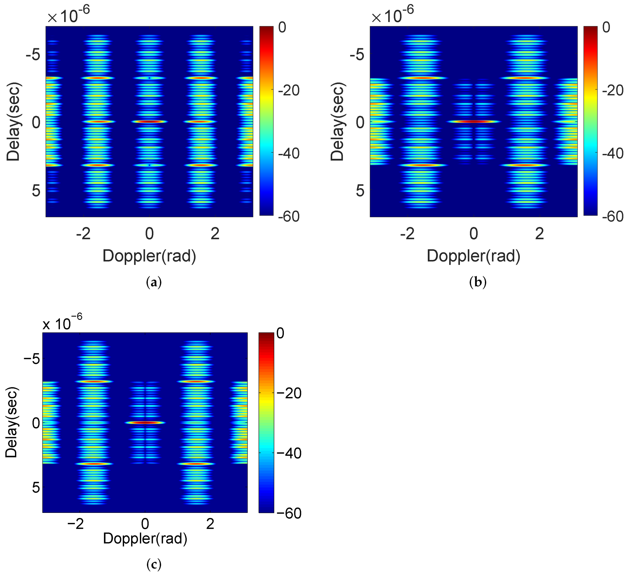
with only 0th order of the null. Figure 1 illustrates the typical ambiguity function of (a) the standard Golay complementary waveforms, (b) that after applying the BD algorithm and (c) the slices across them at Delay = 0 . Clearly, the increasing of spectral null leads to larger sidelobe blanking area (the area where sidelobes are less than 60 dB ) as well as a poor Doppler resolution.
Now we consider the following example:
Example 1.
For N = 8 , the ( P , Q ) sequences for the BD algorithm are
P BD : 0 1 0 1 0 1 0 1 Q BD : C 7 0 C 7 1 C 7 2 C 7 3 C 7 4 C 7 5 C 7 6 C 7 7
As deduced before, the sequence Q BD holds the complementarity of waveforms due to the achievement of high order spectral null, whose sequence pattern is visually observed, where the first and last pulse, the second and the second last pulse, etc, have the same weights when matched filtering, and the largest weights appear in the middle of sequence.

3.2. Generalized Binominal Design Procedure

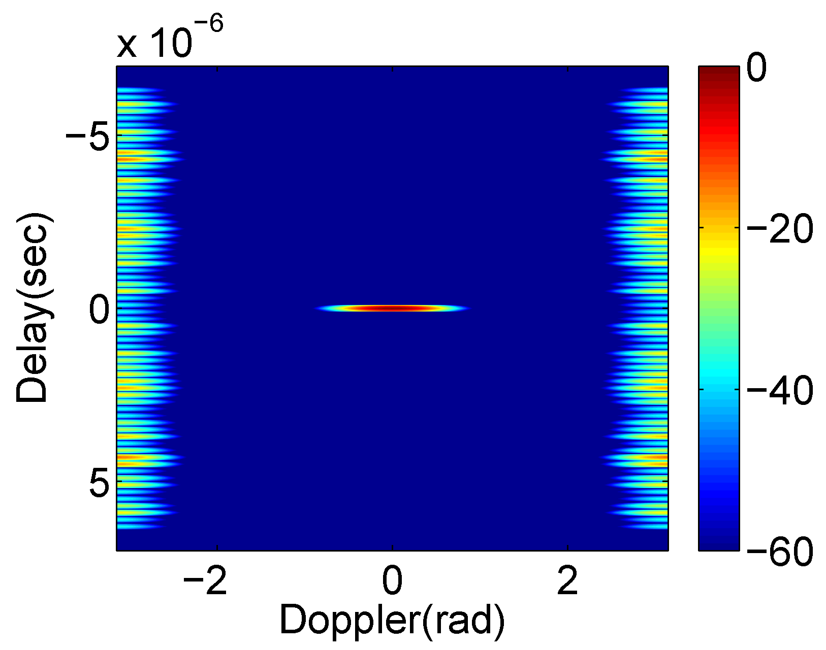
While the BD algorithm is effective for Golay complementary waveforms, we further evaluate its performance on complementary sets. As evidenced from the ambiguity function in Figure 2, the result is the same as Golay complementary waveforms with large sidelobe-free area and low Doppler resolution. However, Figure 1c in the simulation show that the BD algorithm can generate a sidelobe blanking area deeper than 200 dB around zero-Doppler, which is totally not necessary to suppress sidelobes to such a low level during the target detection. Now the problem is, can we do some further work on the BD algorithm, which makes the weights for complementary sets provide higher Doppler resolution under almost the same sidelobe blanking area like Figure 2, allowing a certain extent increase on the sidelobe level?
To address this problem, we propose a Generalized Binominal Design (GBD) procedure in an attempt to achieve higher Doppler resolution as well as a large sidelobe blanking area by using complementary sets. It first transmits complementary sets in standard transmission order and receives the radar return for matched filtering, while the weights selection is motivated from the sequence pattern of BD algorithm but separately designs for the first N / 2 pulses and the last N / 2 pulses according to the following two algorithms:
  • Middle Blanked Design (MBD) algorithm: Indicated by its name, the algorithm designs the weights to suppress the Doppler-induced sidelobes near the center Doppler shift of the ambiguity function. As a result, sidelobes around zero-Doppler are suppressed by the MBD algorithm, but significant sidelobes are still present in the area corresponding to large Doppler shifts (roughly 1.6 rad to 2 rad of absolute values, see in the results shown in Section 4.1). In this algorithm, the P sequence is the standard transmission order of complementary sets, i.e., P GBD = { 0 , 1 , , D 1 , 0 , 1 , , D 1 , } , and the Q sequence is designed as Q MBD = { q MBD ( n ) } n = 0 N 1 = { C N / D 1 floor ( n / D ) × C D 1 mod ( n , D ) } n = 0 N 1 , where floor ( n / D ) rounds the results to the nearest integer no more than n / D , and mod ( n , D ) returns the modulus of n / D .
Example 2.
For a D = 4 complementary set with N = 8 , the ( P , Q ) sequences for the MBD algorithm are
Remotesensing 14 01549 i001
2.
Side Blanked Design (SBD) algorithm: This approach generates weights so that the sidelobe blanked area mainly corresponds to large Dopplers (between 0.7 rad to 2.5 rad of absolute values), as seen in the simulation of Section 4.1. The ( P , Q ) pulse trains for this algorithm are: P GBD = { 0 , 1 , , D 1 , 0 , 1 , , D 1 , } , and Q SBD = { q SBD ( n ) } n = 0 N 1 = { C 2 N / D 1 floor ( 2 n / D ) } n = 0 N 1 .
Example 3.
A complementary set with D = 4 and N = 8 , the ( P , Q ) sequences for the SBD algorithm are
P GBD : 0 1 2 3 0 1 2 3 Q SBD : C 3 0 C 3 0 C 3 1 C 3 1 C 3 2 C 3 2 C 3 3 C 3 3
Note that the SBD algorithm will reduce to the BD algorithm when D = 2 .
According to Ref. [16] we get to know that the spectral null order of both MBD and SBD algorithm are l o g 2 D , therefore they all perform much worse than BD algorithm on sidelobe suppression with better Doppler resolution since D is usually far smaller than N.
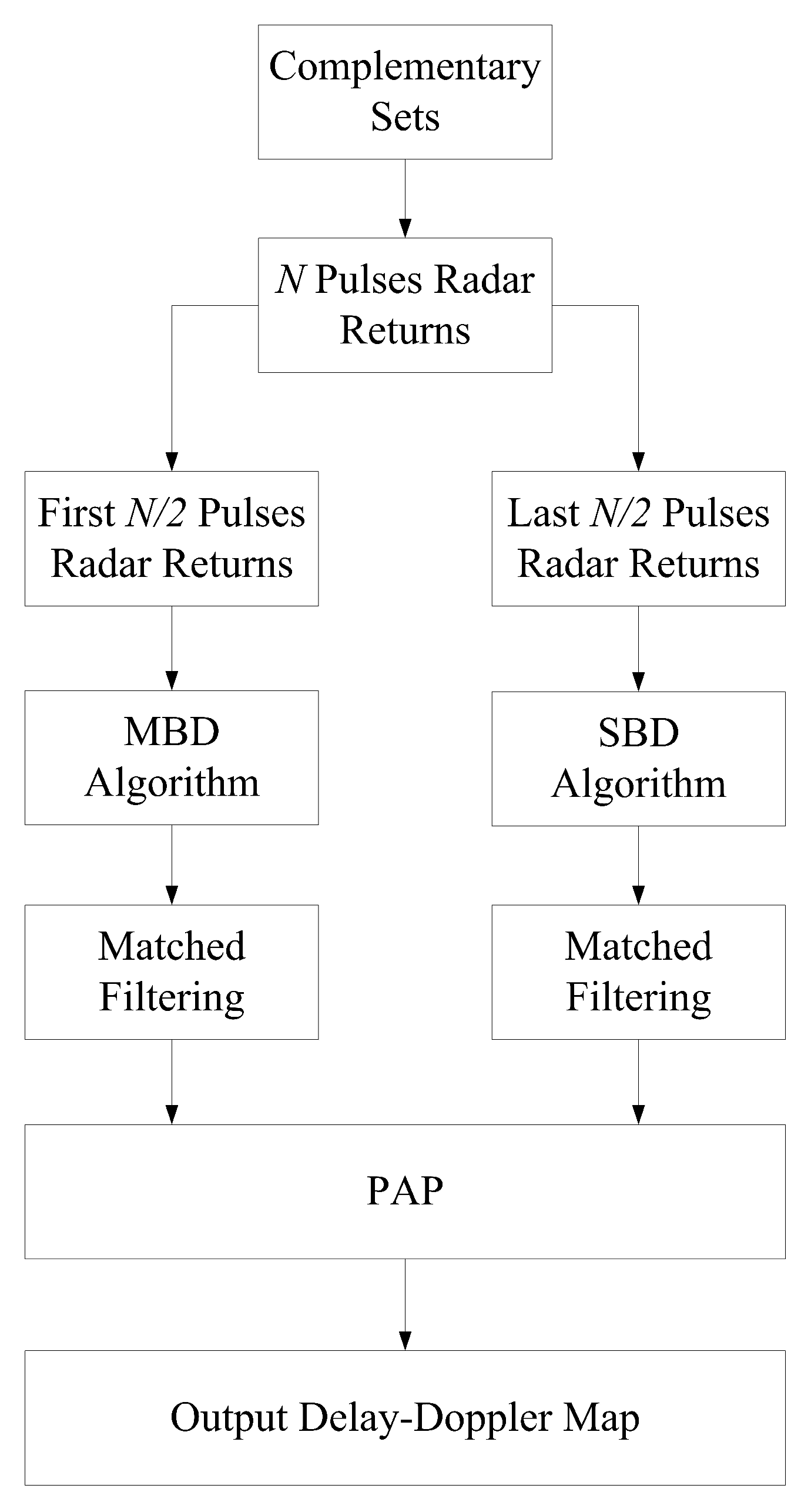
The GBD procedure is illustrated in Figure 3, where χ MBD ( t , F D ) and χ SBD ( t , F D ) are the Delay-Doppler maps obtained from the MBD and SBD algorithm, respectively; χ GBD ( t , F D ) denotes the final Delay-Doppler map of the GBD procedure. To retain the same accumulated number of pulses as the BD algorithm, the GBD procedure separately processes the first N / 2 pulses through the MBD algorithm and the last N / 2 pulses through the SBD algorithm, and combines the outputs using a pointwise addition processor (PAP) to produce the final result
χ GBD ( t , F D ) = norm χ MBD ( t , F D ) + χ SBD ( t , F D )
where “norm” is the normalization operation, which makes the magnitude the same as that in χ MBD ( t , F D ) and χ SBD ( t , F D ) .
The operation of PAP is based on the assumption that the target is stable during the entire radar illumination period. Under this assumption, the following results are summarized:
(i)
The signal energy from the target is preserved during the process, whilst that for sidelobes is randomly distributed and thus flatter over the Delay-Doppler map than the outputs of either MBD or SBD algorithm (e.g., if the magnitude of target in the Delay-Doppler map of MBD and SBD algorithm are both 0 dB , while the sidelobe at a certain point are 10 dB and 30 dB respectively, then the PAP output remains magnitude of target at 0 dB , and normalizes the sidelobe to 20 dB ), with an overall level less than 60 dB in the Doppler interval of interest ( [ 2.5 , 2.5 ]   rad refer to the results in Section 4.1);
(ii)
A comparable sidelobe blanking area as well as a better Doppler resolution are obtained compared with the BD algorithm. Nevertheless, the better performance comes at the cost of the increase of complexity of practical radar system since complex waveforms and weighting schemes are used, and an acceptable decrease of PPSR.
Based on the aforementioned demonstration, a float chart is plotted for better understanding of the principle of the GBD procedure, shown as Figure 4.
Remark 2.
In practice, the Delay-Doppler resolution of the proposed procedure may decrease because the underlying target may perform a micro-motion, as modelled by the Swerling II target model [19]). The fluctuations of a Swerling II target located at ( t , F D ) can be regarded as two independent fluctuations—the delay fluctuation and the Doppler fluctuation, respectively. For detection in far field, these micro-motions can be modeled as independent and identically distributed (IID) Guassian distributions— N ( t ^ , σ T 2 ) and N ( F ^ D , σ D 2 ) , where t ^ and F ^ D are the estimated (mean) values of target delay and Doppler and these can be separately obtained from a tracker; σ T 2 and σ D 2 are their variance values.
Figure 5 highlights the impact of Swerling II target location uncertainties on actual Delay-Doppler resolution in the output of PAP, where 2 R T × 2 R D is the original Delay-Doppler resolution of the Swerling II target. The actual Delay-Doppler resolution of the PAP output is reduced to ( 2 R T + σ T ) × ( 2 R D + σ D ) (Note that the noise in the illumination scene also deteriorates the Delay-Doppler resolution depending on the level of SNR [20], which is not considered in the ambiguity function analysis in this work).

3.3. Performance of the BD Algorithm & the GBD Procedure

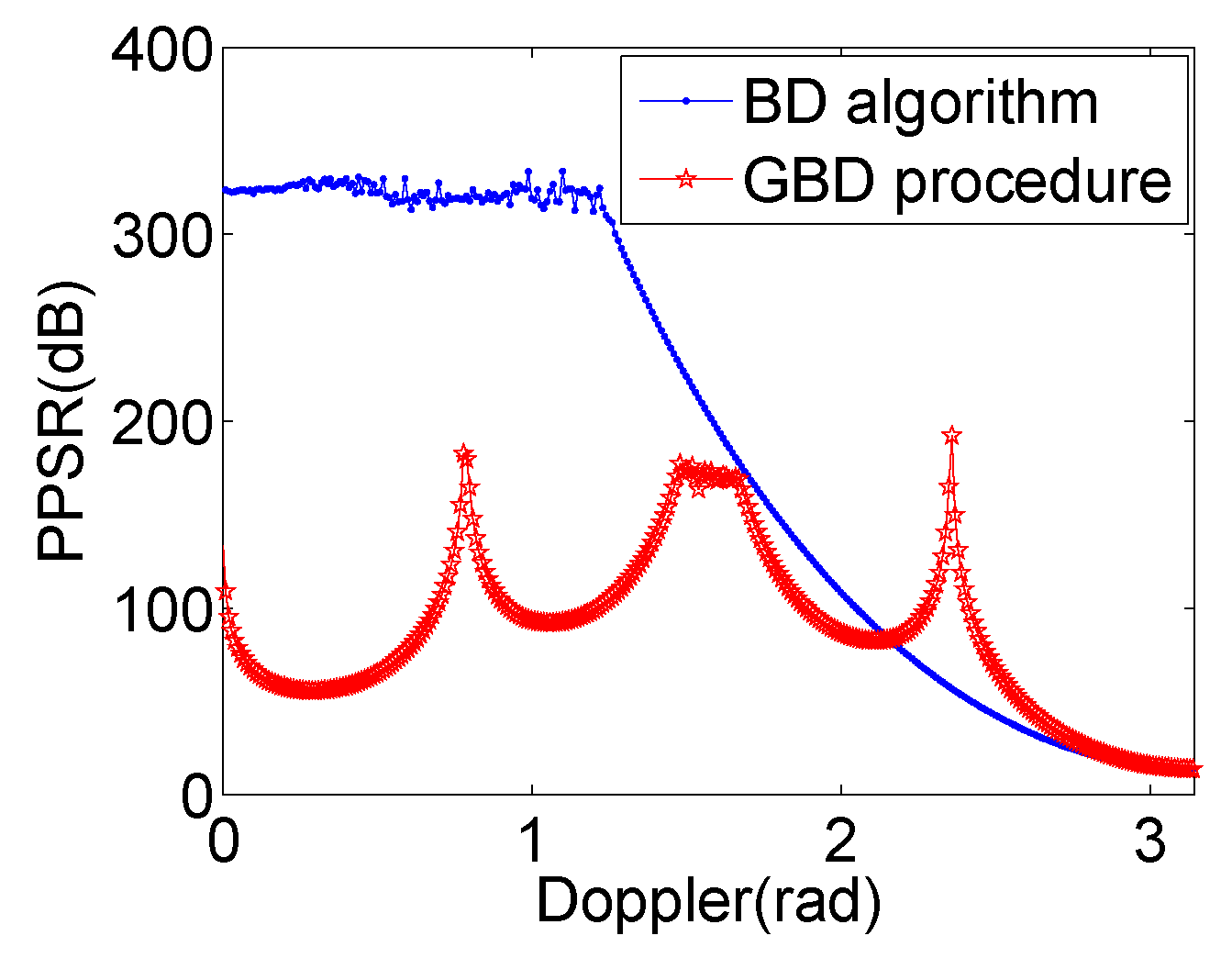
The performance of the BD algorithm and GBD procedure is measured by the peak-to-peak-sidelobe ratio (PPSR) defined in [16], which is a useful measure for evaluating the sidelobe suppression performance.
PPSR ( F D ) = | χ P Q ( 0 , 0 ) | 2 max t S d | χ P Q ( t , F D ) | 2
where S d contains the delays at which the Doppler-induced sidelobes are located. Specifically, PPSR measures sidelobe suppression for a given Doppler by calculating the ratio of the energy of the peak in the ambiguity function (the target) to that of the largest sidelobe at Doppler F D .
For the GBD procedure, PPSR makes a balance with a global enhancement to that of the MBD and SBD algorithms via the PAP. The sidelobe suppression performance of the GBD procedure and the BD algorithm will be compared and further discussed with numerical simulations in Appendix A based on this metric.

4. Numerical Simulations and Discussions

The performance of GBD is examined by numerical simulations, with the following global parameters: the radar carrier frequency is f c = 1 GHz , bandwidth is B = 10 MHz , sampling rate is f s = 10 B , PRI is T = 50 μ s , number of pulses N = 2 6 = 64 . The number of chips in the sequences is L = 64 for both the Golay complementary waveforms and complementary sets, with values ± 1 and chip interval T c = 0.1 μ s .

4.1. Ambiguity Functions Analysis

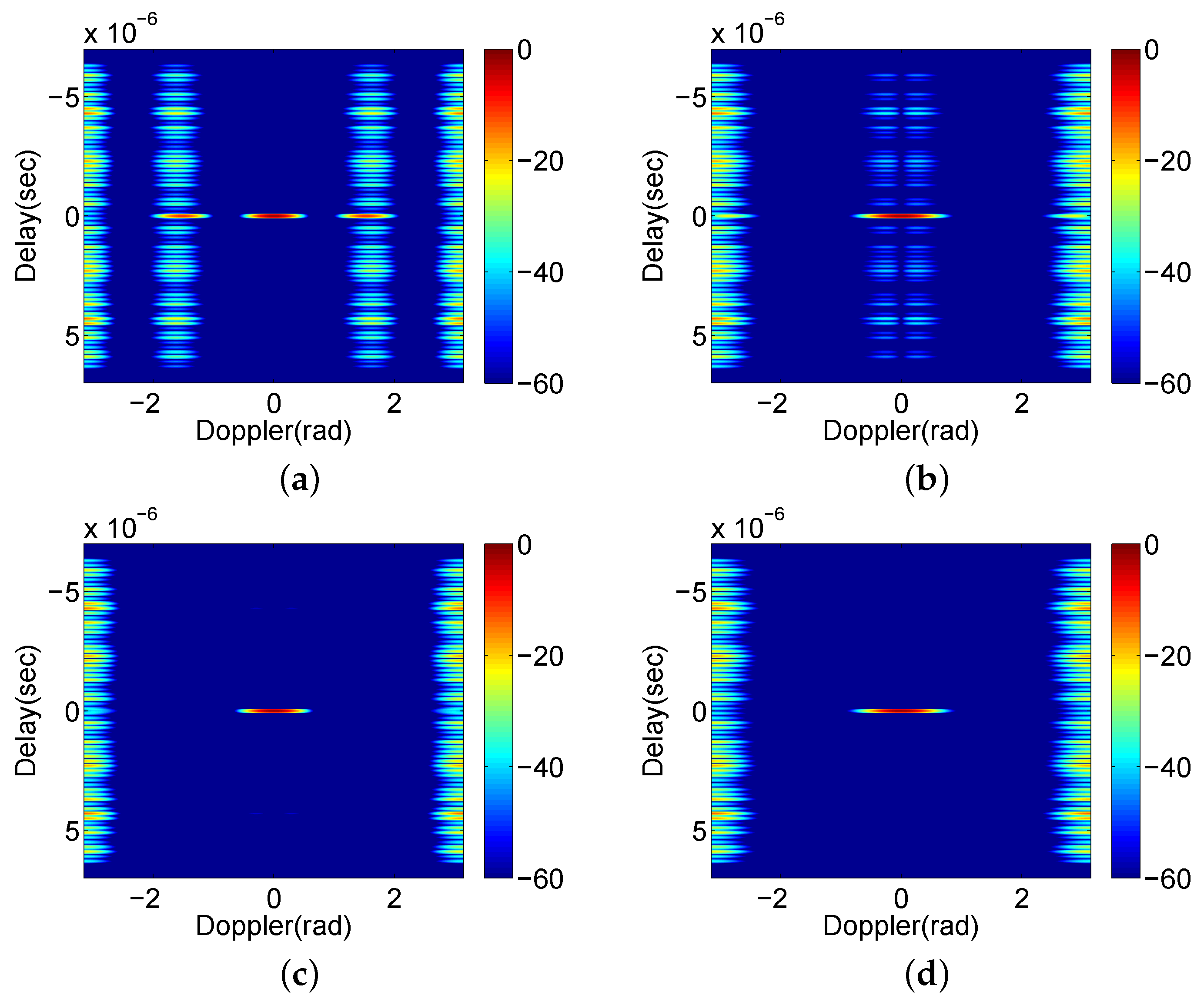
To maintain the same processing time (number of accumulating pulses) as the existing BD algorithm (see Figure 3), the first N / 2 pulses are processed by the MBD algorithm and the SBD algorithm is applied on the last N / 2 pulses, and the PAP method is used in the final step of GBD procedure. In Figure 6, we present the ambiguity functions of MBD algorithm, SBD algorithm, GBD procedure, and BD algorithm.
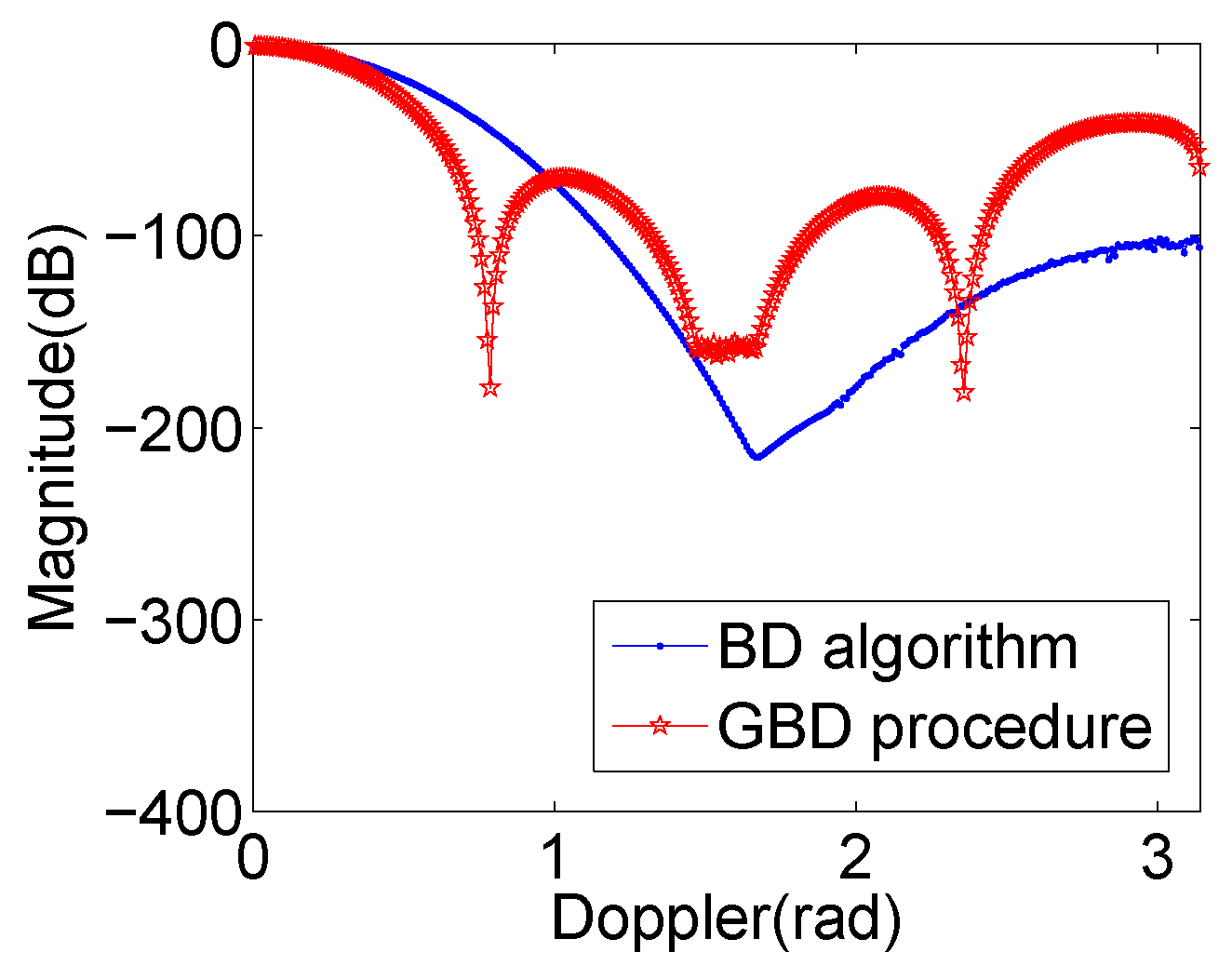
The Figure 6c indicates that the GBD procedure achieves a similar performance as that of the existing BD algorithm (Figure 6d) in terms of sidelobe blanking area. Slices across these two ambiguity functions at the zero-Delay are compared in Figure 7, which shows that the GBD procedure obtains a narrower mainlobe width (i.e., higher Doppler resolution) than the BD algorithm. Particularly at the display level of 60 dB , GBD enhances the Doppler resolution for about 28 % (from 0.9 rad to 0.65 rad).
Besides, σ T and σ D are also considered to simulate the Swerling II fluctuation, which is displayed in Figure 8. In this simulation, σ T and σ D are set to be 0.04 μ s and 0.3 rad , about half of R T and R D , and the result shows a decrease on the Delay-Doppler resolution and a similar shape of target peak to that illustrates in Figure 5.

4.2. PPSR Comparisons

The PPSR performance comparison between the BD and GBD methods is presented in Figure 9. We observe that in the Doppler interval of [ 0 , 2.158 ] rad , most of the PPSR values of BD algorithm are much larger (over 200 dB ) than those of GBD due to the extreme sidelobe suppression ability of BD; that is, GBD actually generates higher sidelobes than the BD algorithm within the sidelobe blanking area, though visually look the same in the ambiguity functions. In other parts of the ambiguity function, GBD performs better than the BD algorithm in sidelobe suppression. Nevertheless, the mean PPSR of GBD is greater than 87 dB , which is high enough for differentiating target returns from range sidelobes.

4.3. Comparing to Conventional Waveform

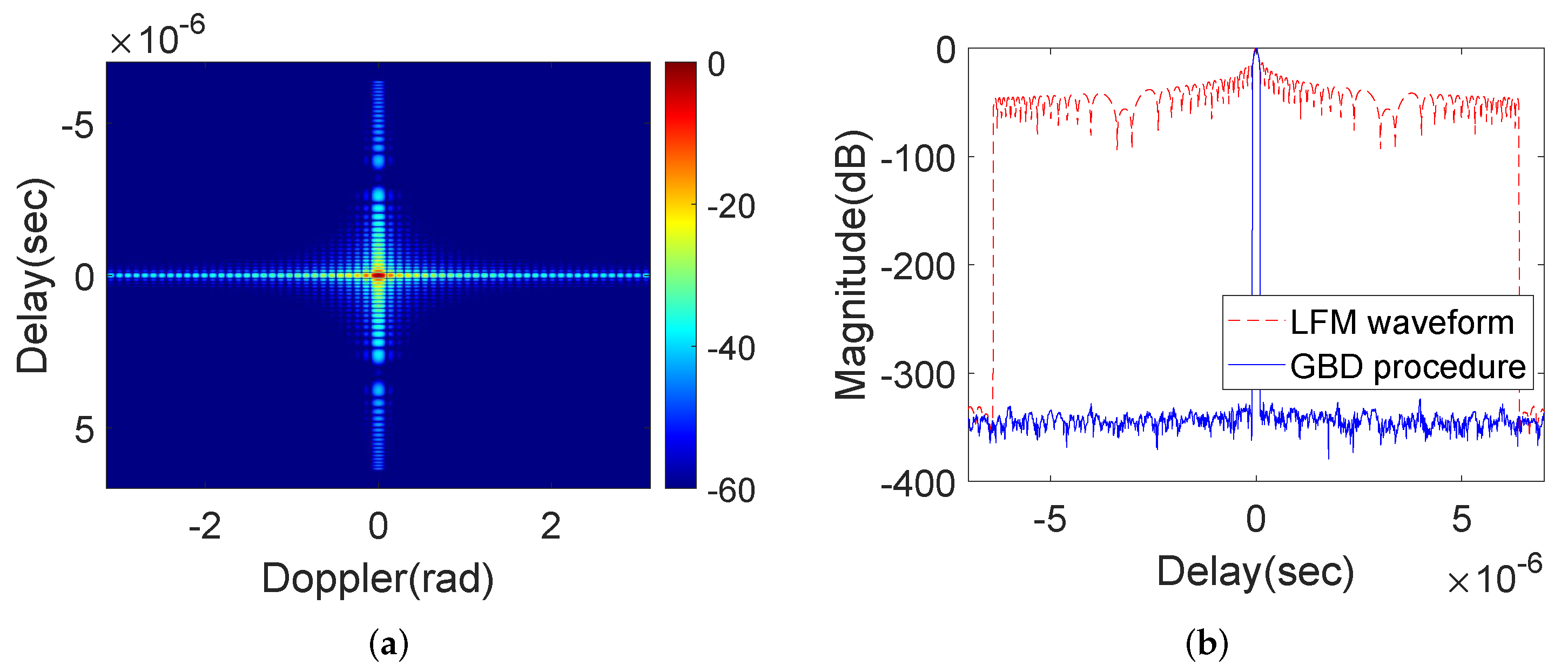
In this Section, analysis is continued for the comparison to a conventional waveform, specially to the linear frequency modulation (LFM) scheme. The ambiguity function of the LFM waveform generated by the same global parameters at the beginning of Section 4, and a slice result at zero-Doppler axis compared to the proposed procedure are plotted in Figure 10. It is observed that the LFM waveform has the same Delay resolution as all the coordinating complementary set schemes in the paper, and has comparable Doppler resolution as standard complementary sets (readers could check Figure 1a), which is over 6 times higher than the proposed method ( 0.1 rad vs. 0.65 rad), while exerts 300 dB higher sidelobes along the zero-Doppler.

5. Conclusions

The main contribution of this paper is the presentation of GBD method for Doppler-induced sidelobe suppression in radar detection using complementary sets, which provide a branch to the effective coordinative design methods of complementary sets. Our analysis shows that the GBD procedure performs as good as the existing BD algorithm in terms of the scale of sidelobe blanking area and processing time but with an enhanced Doppler resolution of about 28 % compared to BD (although still six times lower than the LFM and standard complementary sets) at the cost of acceptable reduction of PPSR. Further performance discussions of sidelobe suppression with respect to the generation patterns for the complementary sets is also analyzed. Numerical simulations are presented to demonstrate the improvement of the proposed procedure. Future avenues may direct the practical validation of the proposed approach.

Author Contributions

Conceptualization and supervision, X.H.; methodology, J.Z., Y.S. and C.F.; software validation, J.Z., B.Z. and Y.M.; writing—original draft preparation, J.Z.; writing—review and editing, Y.S. and C.F.; funding acquisition, J.Z., B.Z. and Y.M. All authors have read and agree to the published version of the manuscript.

Funding

This work was partly supported by the National Natural Science Foundation of China under grant 62101573, Natural Science Foundation of Hunan Province, China under grant 2020JJ5677, and the scientific research project of National University of Defense Technology under grant ZK20-35, ZK20-39 and ZK19-36.

Acknowledgments

The authors would like to thank Bill Moran and Xuezhi Wang from the University of Melbourne and RMIT University for the sufficient discussion on this work, and also thank the editors and reviewers for their valuable suggestions for the improvement of the manuscript.

Conflicts of Interest

The authors declare no conflict of interest.

Appendix A. Further Performance Discussions of the Procedure to the Generation Pattern of Complementary Sets

In view of Equations (5)–(7), the ambiguity function of BD algorithm for Golay complementary waveforms is given in Equation (8). Similarly, the ambiguity functions of MBD and SBD algorithms for the first N / 2 and last N / 2 pulses of complementary sets are given in Equations (A1) and (A2), respectively.
χ MBD ( t , F D ) = + z P GBD ( s ) exp ( j 2 π F D s ) z Q MBD * ( t s ) d s = n = 0 N / 2 1 q MBD ( n ) exp ( j 2 π F D n T ) d = 0 p GBD ( n ) = d D 1 a d ( t n T ) a d * ( t n T ) = k = L + 1 L 1 n = 0 N / 2 1 q MBD ( n ) exp ( j 2 π F D n T ) d = 0 p GBD ( n ) = d D 1 C a d ( k ) C Ω ( t k T c n T ) = k = L + 1 L 1 n = 0 N / 2 1 1 D d = 0 D 1 C a d ( k ) q MBD ( n ) exp ( j 2 π F D n T ) C Ω ( t k T c n T ) + k = L + 1 L 1 n = 0 N / 2 1 1 D ( D 1 ) C a p GBD ( n ) ( k ) r = 0 r p GBD ( n ) D 1 C a r ( k ) q MBD ( n ) exp ( j 2 π F D n T ) C Ω ( t k T c n T )
χ SBD ( t , F D ) = k = L + 1 L 1 n = 0 N / 2 1 1 D d = 0 D 1 C a d ( k ) q SBD ( n ) exp ( j 2 π F D n T ) C Ω ( t k T c n T ) + k = L + 1 L 1 n = 0 N / 2 1 1 D ( D 1 ) C a p GBD ( n ) ( k ) r = 0 r p GBD ( n ) D 1 C a r ( k ) q SBD ( n ) exp ( j 2 π F D n T ) C Ω ( t k T c n T )
The first terms of these two equations are contributed by target returns corresponding to the peak of the ambiguity function, with the other terms influence the magnitudes of Doppler-induced sidelobes produced by signal processing. It is observed that the sidelobes are not only determined by the ( P , Q ) sequences, but also influenced by the the generation pattern of the complementary sets, which essentially alter the autocorrelation values of the sequences a d ( t ) .
As shown in [5], there are several ways to generate the complementary sets. Notice that in the previous simulation we only employ the complementary sets consist of several different pairs of Golay complementary waveforms (generated by Theorem 13 of Ref. [5] and contains D / 2 pairs of Golay sequences), denoted as particular complementary sets in the rest of the manuscript. Despite this specific scenario, it is also worth evaluating the performance of our procedure under the general complementary sets, in which any two sequences in the sets are not complementary and their complementarity can only be achieved by summing all the autocorrelations of sequences (say the Theorem 12 of Ref. [5]). Although literatures have researched the numbers of approaches for the generation of particular and general complementary sets [21,22,23], we do not present too many generation patterns for comparison due to the page limitation and only demonstrate the above two patterns without loss of generality. The following discussion illustrates that the proposed GBD procedure can not achieve similar good sidelobe suppression performance as particular complementary sets when using general complementary sets.
After analyzing the generation pattern of these two kinds of complementary sets, the following properties are observed:
Property A1.
For a particular complementary sets with L = 2 γ chips in each sequence, the function g ( d ) = k = L + 1 L 1 C a d ( k ) L , d = 0 , 1 , , D 1 of each sequence has the same absolute value V = 0 when γ is even and V = L when γ is odd, and to hold on the complementarity of Golay complementary waveforms, the number of values + L and L are the same.
Example A1.
A particular complementary sets U = { u 1 , u 2 , u 3 , u 4 } with L = 4 = 2 2 is given in Table A1, in which u 1 , u 2 and u 3 , u 4 are two different pairs of Golay complementary waveforms. “+” and “−” are used to represent the chips of ± 1 elements in the sequences. It is shown that | g U ( d ) | = V = 0 for each sequence in the sets. Besides, as shown in Table A2, | g U ( d ) | = V = 8 for another particular complementary sets U = { u 1 , u 2 , u 3 , u 4 } with L = 8 = 2 3 , and there are both two + 8 and two 8 for all the sequences.
Table A1. Example for the illustration of Property 1 ( L = 4 ).
Particular Complementary SetsAutocorrelation Sequences g U ( d )
u 1 + 1 01410 1 0
u 2 + 10 1 4 1 010
u 3 + 10 1 4 1 010
u 4 + + + 1 01410 1 0
Table A2. Example for the illustration of Property 1 ( L = 8 ).
Particular Complementary Sets g U ( d )
u 1 + + 8
u 2 + + + + 8
u 3 + + + + + + 8
u 4 + + + + 8
Based on this example, we have the following remark:
Remark A1.
The absolute value of g ( d ) for Golay complementary waveforms is always 0 (for even γ) or L (for odd γ), no matter which method is used to generate the waveforms. For instance, the function | g ( d ) | will always calculate to be 0 for the sequences of all the Golay complementary waveforms with L = 4 , to be 8 for all of them with L = 8 , despite of the generation method used.
Property A2.
The function g ( d ) has two absolute value for L = 2 γ chips general complementary sets when γ is even, denoted as V 1 = ( D 1 ) L and V 2 = L ( V 1 and V 2 have different sign in real values, whose number are 1 and ( D 1 ) respectively), and has the same absolute value V 1 = V 2 = L when γ is odd (both the number of + L and L are D / 2 ).
Example A2.
A general complementary sets W = { w 1 , w 2 , w 3 , w 4 } with L = 4 is shown in Table A3, and the g W ( d ) has two absolute values: V 1 = 12 and V 2 = 4 , while the Table A4 expresses that the same absolute value 8 is obtained for a general complementary sets W = { w 1 , w 2 , w 3 , w 4 } with L = 8 chips.
Table A3. Example for the illustration of Property 2 ( L = 4 ).
General Complementary SetsAutocorrelation Sequences g W ( d )
w 1 + + + + 123432112
w 2 + + 1 2 1412 1 4
w 3 + + 1 2 3 4 3 2 1 4
w 4 + + 1 2 1 4 1 2 1 4
Table A4. Example for the illustration of Property 2 ( L = 8 ).
General Complementary Sets g W ( d )
w 1 + + + + + + 8
w 2 + + + + + + 8
w 3 + + + + 8
w 4 + + + + 8
Property A3.
For the particular and general complementary sets with identical L chips in each sequence, V min { V 1 , V 2 } .
Illustrations of this property are given in Examples A1 and A2, under the condition that L = 4 , the V in Example A1 is 0, which is less than min { V 1 , V 2 } = 4 in Example A2, while V = V 1 = V 2 = 8 in the two examples for L = 8 .
Based on the above analysis, we further explore the sidelobes under the different sequence patterns of complementary sets with identical number of chips L. As discussed before, the first terms in Equations (A1) and (A2) are free of sidelobe, thus the sidelobes induced by the varies of sequence pattern are only affected by the terms
k = L + 1 L 1 C a 0 ( k ) C a 1 ( k ) and k = L + 1 L 1 ( D 1 ) C a p GBD ( n ) ( k ) r = 0 r p GBD ( n ) D 1 C a r ( k )
in Equations (A1) and (A2), respectively, to the Golay complementary waveforms and complementary sets. The larger absolute values these two terms have, the higher overall magnitude of sidelobes they will induce.
We first consider Equation (8)—the case of Golay complementary waveforms. According to the Remark A1,
k = L + 1 L 1 C a 0 ( k ) C a 1 ( k ) = k = L + 1 L 1 C a 0 ( k ) ( C a 1 ( k ) ) = 2 ( V + L )
It is stable for a given L, which means that different sequence patterns of Golay complementary waveforms will not increase the total magnitude of sidelobes.
On the other hand, Equation (A1) involves particular complementary sets,
k = L + 1 L 1 ( D 1 ) C a p GBD ( n ) ( k ) r = 0 r p GBD ( n ) D 1 C a r ( k ) = k = L + 1 L 1 ( D 1 ) C a p GBD ( n ) ( k ) ( C a p GBD ( n ) ( k ) ) = D ( V + L )
while Equation (A2) is for general complementary sets,
k = L + 1 L 1 ( D 1 ) C a p GBD ( n ) ( k ) r = 0 r p GBD ( n ) D 1 C a r ( k ) = D ( V m + L ) m = 1 , 2 .
Because of Property A3, V V m , therefore the Doppler-induced sidelobes generated by particular complementary sets are no higher than that invoked by general complementary sets in global magnitudes.
In summary, under a fixed design scheme of ( P , Q ) sequences for complementary sets, the sequence pattern of the sets will also influence the overall magnitudes of Doppler-induced sidelobes. Specifically, it is shown that particular complementary sets induce lower sidelobes in total than general complementary sets. This will be further validated in the following simulations. Figure 6c demonstrates the ambiguity function of the GBD procedure when the particular complementary sets are used for transmission. For comparison, we plot another ambiguity function of GBD by replacing the particular complementary sets to general complementary sets in the transmitter, which is illustrated in Figure A1c. Clearly, the performance of the latter is poor in the sense of further interference of sidelobes. The comparison of PPSR in Figure A2 also indicates that a better sidelobe suppression performance can be achieved when a particular generation pattern of complementary sets is employed.
Figure A1. The ambiguity function of the GBD procedure using the example general complementary sets: (a) MBD algorithm; (b) SBD algorithm; (c) GBD procedure. (the unit of colorbar is dB).
Remotesensing 14 01549 g0a1
Figure A2. The PPSR of general/particular complementary sets.
Remotesensing 14 01549 g0a2

References

  1. Golay, M. Complementary series. IRE Trans. Inform. Theory 1961, 7, 82–87. [Google Scholar] [CrossRef]
  2. Calderbank, R.; Howard, S.D.; Moran, B. Waveform diversity in radar signal processing. IEEE Signal Process. Mag. 2009, 26, 32–41. [Google Scholar] [CrossRef]
  3. Pezeshki, A.; Calderbank, A.R.; Moran, W.; Howard, S.D. Doppler resilient Golay complementary waveforms. IEEE Trans. Inform. Theory 2008, 54, 4254–4266. [Google Scholar] [CrossRef] [Green Version]
  4. Dang, W.; Pezeshki, A.; Howard, S.; Moran, W.; Calderbank, R. Coordinating complementary waveforms for sidelobe suppression. In Proceedings of the 45th Asilomar Conference on Signals, Systems and Computers, Pacific Grove, CA, USA, 6–9 November 2011; pp. 2096–2100. [Google Scholar] [CrossRef] [Green Version]
  5. Tseng, C.C.; Liu, C. Complementary sets of sequences. IEEE Trans. Inform. Theory 1972, 18, 644–652. [Google Scholar] [CrossRef]
  6. Farnane, K.; Minaoui, K. Analysis of the radar ambiguity function for a new Golay sets shaping. In Proceedings of the 2020 10th International Symposium on Signal, Image, Video and Communications (ISIVC), Tokyo, Japan, 7–9 April 2021; pp. 1–4. [Google Scholar] [CrossRef]
  7. Aparicio, J.; Shimura, T. Asynchronous detection and identification of multiple users by multi-carrier modulated complementary set of sequences. IEEE Access 2018, 6, 22054–22069. [Google Scholar] [CrossRef]
  8. Koshevyy, V.; Popova, V. Complementary coded waveforms sets in marine radar application. In Proceedings of the 2017 IEEE First Ukraine Conference on Electrical and Computer Engineering (UKRCON), Kyiv, Ukraine, 29 May–2 June 2017; pp. 215–220. [Google Scholar] [CrossRef] [Green Version]
  9. Searle, S.; Howard, S.; Moran, B. The use of complementary sets in MIMO radar. In Proceedings of the 2008 42nd Asilomar Conference on Signals, Systems and Computers, Grove, CA, USA, 26–29 October 2008; pp. 510–514. [Google Scholar] [CrossRef]
  10. Searle, S.; Howard, S. Waveform design and processing for multichannel MIMO radar. In Proceedings of the 2009 International Radar Conference “Surveillance for a Safer World”, Bordeaux, France, 12–16 October 2009; pp. 1–6. [Google Scholar]
  11. Tang, J.; Zhang, N.; Ma, Z.; Tang, B. Construction of Doppler resilient complete complementary code in MIMO radar. IEEE Trans. Signal Process. 2014, 62, 4704–4712. [Google Scholar] [CrossRef]
  12. Nguyen, H.D.; Coxson, G.E. Doppler tolerance, complementary code sets, and generalised Thue-Morse sequences. IET Radar Sonar Navig. 2016, 10, 1603–1610. [Google Scholar] [CrossRef]
  13. Zhu, J.; Wang, X.; Huang, X. Range sidelobe suppression for using Golay complementary waveforms in multiple moving target detection. Signal Process. 2017, 141, 28–31. [Google Scholar] [CrossRef]
  14. Zhu, J.; Chu, N.; Song, Y.; Yi, S.; Wang, X.; Huang, X.; Moran, B. Alternative signal processing of complementary waveform returns for range sidelobe suppression. Signal Process. 2019, 159, 187192. [Google Scholar] [CrossRef]
  15. Wu, Z.J.; Zhou, Z.Q.; Wang, C.X.; Li, Y.C.; Zhao, Z.F. Doppler resilient complementary waveform design for active sensing. IEEE Sens. J. 2020, 20, 9963–9976. [Google Scholar] [CrossRef]
  16. Dang, W. Signal Design for Active Sensing. Ph.D. Thesis, Colorado State University, Fort Collins, CO, USA, 2014. [Google Scholar]
  17. Richards, M.A. Fundamentals of Radar Signal Processing; McGraw-Hill Education: New York, NY, USA, 2005. [Google Scholar]
  18. Zhu, J.; Wang, X.; Song, Y.; Huang, X.; Moran, B. Range sidelobe suppression using complementary sets in distributed multistatic radar networks. Sensors 2018, 18, 35. [Google Scholar] [CrossRef] [PubMed] [Green Version]
  19. Skolnik, M. Introduction to Radar Systems, 3rd ed.; McGraw-Hill Education: New York, NY, USA, 2001. [Google Scholar]
  20. Ojha, A.K.; Koch, D.B. Impact of noise and target fluctuation on the performance of binary phase coded radar signals. Proc. IEEE Southeastcon 1992, 1, 215–218. [Google Scholar] [CrossRef]
  21. Davis, J.; Jedwab, J. Peak-to-mean power control in OFDM, Golay complementary sequences, and Reed-Muller codes. IEEE Trans. Inf. Theory 1999, 45, 2397–2417. [Google Scholar] [CrossRef] [Green Version]
  22. Liu, Z.; Guan, Y.L.; Parampalli, U. New complete complementary codes for peak-to-mean power control in multi-Carrier CDMA. IEEE Trans. Commun. 2014, 62, 1105–1113. [Google Scholar] [CrossRef]
  23. Das, S.; Budišin, S.; Majhi, S.; Liu, Z.; Guan, Y.L. A multiplier-free Generator for polyphase complete complementary codes. IEEE Trans. Signal Process. 2018, 66, 1184–1196. [Google Scholar] [CrossRef]
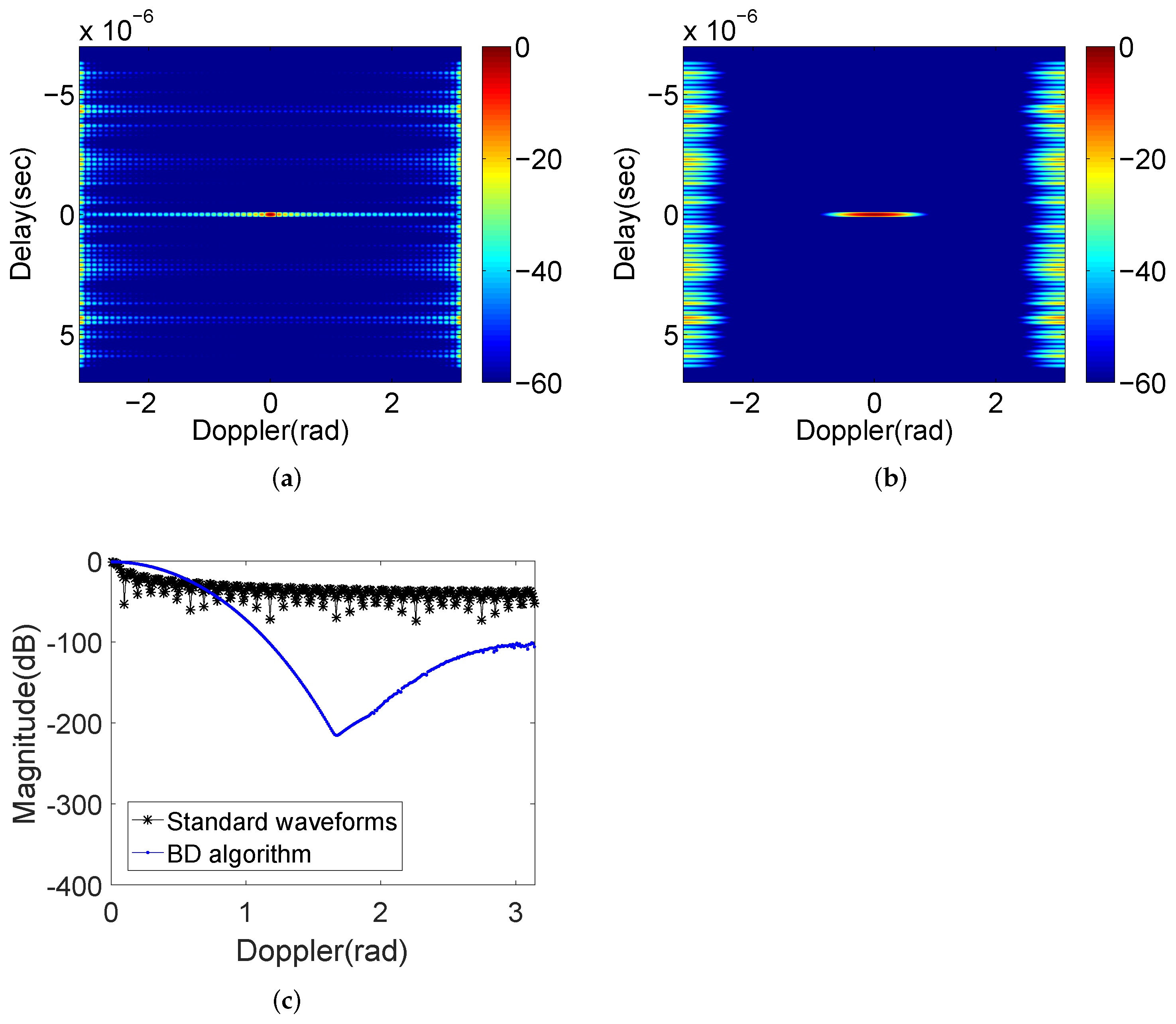
Figure 1. The ambiguity function of Golay complementary waveforms based on (a) standard transmission order and weighting sequence; (b) the BD algorithm; (c) Slices at Delay = 0. (unit in the colorbar is dB and the parameters setting of this figure are described in Appendix A).
Remotesensing 14 01549 g001
Figure 2. The ambiguity function of complementary sets using the BD algorithm. (unit in the colorbar is dB).
Remotesensing 14 01549 g002
Figure 3. The schematic of the GBD procedure.
Remotesensing 14 01549 g003
Figure 4. Float chart of the GBD procedure.
Remotesensing 14 01549 g004
Figure 5. The location uncertainties of a Swerling II target to the decrease of Delay-Doppler resolution after PAP.
Remotesensing 14 01549 g005
Figure 6. The ambiguity functions of (a) MBD algorithm; (b) SBD algorithm; (c) GBD procedure; (d) BD algorithm. (the unit of colorbar is dB).
Remotesensing 14 01549 g006
Figure 7. The slices across at Delay = 0 of the ambiguity functions of BD algorithm and GBD procedure.
Remotesensing 14 01549 g007
Figure 8. The ambiguity functions of GBD procedure with Swerling II fluctuation.
Remotesensing 14 01549 g008
Figure 9. The comparison of PPSR between the BD algorithm and the GBD procedure.
Remotesensing 14 01549 g009
Figure 10. (a) The ambiguity functions of LFM waveform (the unit of colorbar is dB); (b) zero-Doppler slice comparison with GBD procedure.
Remotesensing 14 01549 g010
Publisher’s Note: MDPI stays neutral with regard to jurisdictional claims in published maps and institutional affiliations.