


Abstract
The space–air–ground Integrated Network (SAGIN) is considered to be a significant framework for realizing the vision of “6G intelligent connection of all things”. The birth of 6G SAGIN also brings many problems, such as ultra-dense dense networks, leading to a decrease in the efficiency of traditional flat network management, and traditional satellite networking solidified network functions, etc. Therefore, combining the 6G SAGIN network with the software-defined network (SDN) is an excellent solution. However, the satellite network topology changes dynamically and the ground user unbalanced distribution leads to the unbalanced load of the SDN controller, which further leads to the increased communication delay and throughput drop, etc. For these problems, a hierarchical multi-controller deployment strategy of an SDN-based 6G SAGIN is proposed. Firstly, the delay model of the network, the load model of the SDN controller, and a loss value as a measure of whether the network delay and controller load are optimal are defined. Then, using the distribution relationship between the SDN controller and the switch node as the solution space, and taking the loss value as the optimization goal, a multi-controller deployment strategy based on the simulated annealing algorithm is used to search for the optimal solution space. Lastly, considering the network topology changes dynamically and the SDN controller imbalance, a switch migration strategy oriented toward load balancing is proposed. We aimed to determine the controller deployment plan through the above two points, balance the controller load, and then improve the network performance. The simulation results show that the controller load is increased by about 7.71% compared to OCLDS, and the running time is increased by 17.7% compared to n-k-means.
1. Introduction
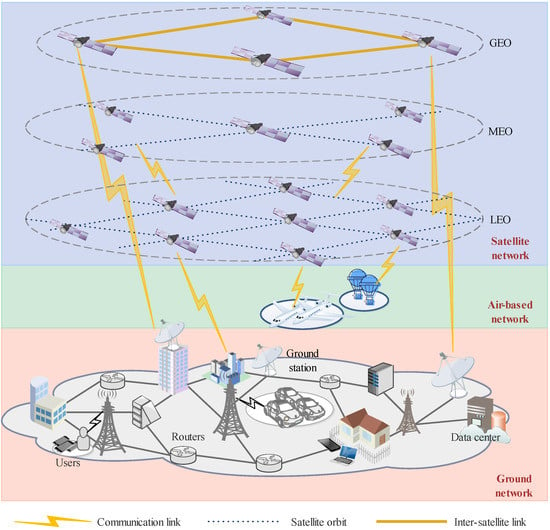
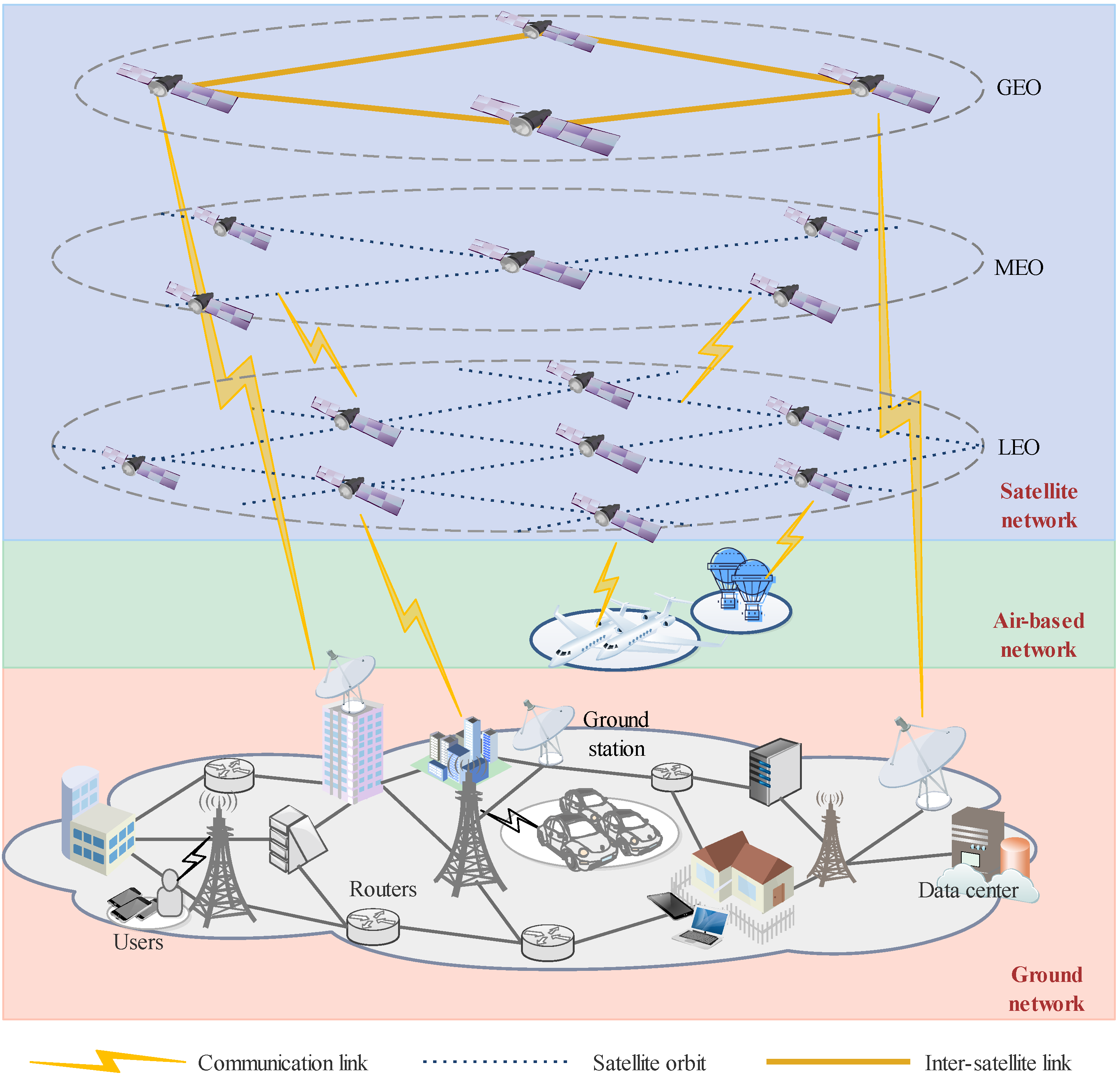
With the development of science and technology, 5G has entered the stage of commercial application, and more studies have begun to focus on the development of 6G. The vision of 6G communication in the future is the intelligent connection of all things, breaking through the limitations of terrain and surface, expanding to natural space such as space, sky, land, and sea, and truly realizing the universal ubiquitous connection [1,2]. The space–air–ground integrated network (SAGIN), which combines the airspace network, sky domain network, and ground network, has become a trend to realize the vision of “6G intelligent connection with everything” [3,4]. The SAGIN architecture is considered as an important framework for the future communication network because it has the characteristics of a space-based network and satellite-based network, such as wide coverage, high flexibility, strong cloud-edge cooperation [5], and the high transmission rate of a ground network [3]. SAGIN is a layered network architecture consisting of satellite networks, space-based networks, and ground-based networks. As shown in Figure 1, a geosynchronous orbit (GEO) satellite, medium-earth orbit (MEO) satellite and low-earth orbit (LEO) satellite constitute the satellite network communication system. The space-based network communication system is composed of a high-altitude platform (HAP) and low-altitude platform (LAP), such as unmanned aerial vehicle (UAV) formation, space aerostats, airships and hydrogen balloons. The ground-based network consists of a cellular wireless network, satellite ground station, ground data processing center, ground stations, ground Internet of Vehicles, etc. [6,7,8,9,10,11]. So, a large-scale network composition model will inevitably face many problems, such as the solidification of the functions of the traditional satellite networking model, and extremely complex upgrades and maintenance. The traditional flat management-intensive network nodes lead to a sharp drop in network delay and throughput, and load imbalances between nodes are prone to appearing. The network is highly heterogeneous, and different network dimensions require different communication protocols and communication links, resulting in increased network management complexity and increased operating network costs [12,13].
Figure 1.
Hierarchical 6G space–air–ground integrated network architecture.
To realize the global optimization of resources and the cooperation of heterogeneous networks in such a large-scale network, a current trend is to introduce the idea of SDN centralized perception and data/control decoupled network design into the design of SGAIN [14,15,16,17,18]. SDN uses the layering to separate the data plane of the network from the control plane, and the control plane controls the network equipment of the data plane centrally through the unified and open south interface; it also uses network function virtualization (NFV) technology to abstract the physical network and device components, decouples the physical device layer and the business logic layer, collects the state information of the whole network from the control plane, and creates an efficient resource allocation strategy. The data plane is only responsible for forwarding the resource according to the command of the control plane. The centralized control feature of SDN enhances the resource utilization of space-based networks, and supports the global information acquisition of network resources and the global allocation and optimization of resources according to service requirements in [19,20]. The SDN open programming interface, namely the north and south interface, makes an application layer and control layer; the control layer and network layer are seamlessly connected through a custom application to make SAGIN more efficient in [21]. An SDN-enabled SAGIN can simplify the complexity of the network and improve the network performance, but it needs an efficient network design scheme, that is, the SDN-enabled multi-controller deployment strategy.
Therefore, this paper proposes a multi-controller deployment strategy based on a simulated annealing algorithm and a switch migration strategy oriented toward load balancing for the SDN-based 6G space–air–ground integrated network. Unlike previous work, satellite gateways and controllers are jointly deployed, or all controllers are deployed on satellites. The optimization goal is singular, and the deployment strategy does not consider network topology dynamics. This paper hierarchically deploys controllers on the ground network: the main controller is deployed at the network operation controller center, and the domain controller is deployed near the ground station to minimize the time delay loss from the ground station to the controller. The deployment strategy jointly optimizes the network propagation delay and controller load. The switch migration strategy oriented toward load balancing solves the problem of load imbalance caused by the network topology changes dynamically. In short, the main contributions of this article are as follows:
- Firstly, based on the hierarchical SDN-enabled 6G SAGIN model, the controller hierarchical network design scheme is adopted, and the delay model of the network and the load model of the controller are constructed. The loss value, as an important basis for network division, is defined by combining the delay model and the load model.
- Then, in order to obtain the global optimal solution and reduce the time complexity of the algorithm, a multi-controller deployment strategy based on simulated annealing is proposed, and a concrete deployment scheme is given according to different delay and load requirements.
- Finally, considering the dynamic nature of the network topology, a switch migration strategy is proposed, in order to achieve load balance among the controllers, and some switches within the jurisdiction of the high-load controller are selected to be transferred to the low-load controller, improving the utilization of network resources. Due to the need to implement this strategy at certain intervals to avoid load imbalance between the controllers, resulting in a sharp decline in network performance, the time complexity of the switch migration algorithm cannot be too high.
The rest of this paper is organized as follows: Section 1.1 and Section 1.2 introduce the related work of the SDN-enabled 6G SAGIN and multi-controller deployment strategy. Section 2 introduces the hierarchical and domain SDN-based 6G SAGIN architecture. The multi-controller deployment problem SDN-based 6G SAGIN is described as a mathematical model and a hierarchical and domain multi-controller deployment strategy. Section 3 compares and analyzes the performance of this strategy and gives a feasible deployment plan. Section 4 summarizes this article.
With the proposal of the SDN-enabled SAGIN, more and more studies are focused on how to design the hierarchical structure of the network and how to deploy the SDN controller reasonably in order to solve the problem of network delay, link throughput and other network performance degradation problems caused dynamic changes in SAGIN, the unbalanced distribution of large-scale nodes and strong heterogeneity.
1.1. In SDN-Enabled SAGIN Architecture Design
The SDN multi-controller deployment architecture can be divided into two types: a flat design and layered design. In [22,23], a cross-domain SDN network architecture for a multi-layer SAGIN is proposed. The data plane includes satellites, aircraft, and ground networks [24]. The control plane is divided into two layers, consisting of the main controller layer and the secondary controller layer. The secondary controller layer is deployed in the space-based network, air-based network, and ground-based network, respectively, and cross-network communication is realized through the main controller. It is a layered design. N. Zhang in [21] and Wu, Hua Qing, et al. in [25] also used a multi-controller hierarchical design method to propose a software-defined space–air–ground integrated vehicle network to achieve flexible, reliable and scalable network resource management. D Wei, N Wei, et al. in [26] use a flat multi-controller deployment design in the software-defined satellite network. The control plane is composed of geostationary satellites, and the data plane includes low-orbit satellites, space-based networks and ground networks. This solution avoids dynamic changes in the network topology, but brings tremendous pressure to the geostationary satellite.
1.2. In Terms of Multi-Controller Deployment Strategies
Researchers focused on optimizing network and controller loads in [27,28,29]. Mostafaei H, Menth M, et al. in [30] abstract the controller deployment problem as an NP-hard problem, and propose a learning automata-based heuristic with the goal of minimizing the propagation delay between switches and controllers in the network. This is a static deployment, with no consideration for topo dynamics. Qu in [31] and Qi et al. in [32] aimed to minimize the propagation delay of switches and controllers. The former propose an SDN-enabled SAGIN architecture, and optimize the K-means algorithm to solve the controller deployment problem of the dynamic topology network composed of UAV in the air-based domain, hereinafter referred to as n-k-means. The latter proposed a clustering algorithm based on improved density peaks to solve the multi-controller deployment problem. The algorithm has achieved significant results in optimizing the delay, but the load of a single controller cannot be controlled, which is a disaster for the scarcity of satellite resources. D Wei, N Wei, et al. in [26] proposed a strategy to migrate switch nodes under the administration of an idle controller and high-load controller to an adjacent low-load controller (hereinafter referred to as OCLDS) to reduce network delay and improve network throughput, considering the large load difference between SDN-based satellite network controllers. The load balancing effect of the controller is significant, but the disconnection and connection process between the switch node and the controller is time consuming, resulting in a delay that is not well controlled. P. Tao, C. Ying, et al. in [33] considered the routing times of a switch controller to the switch of the routing number and the number of routes between controllers, based on the load balancing factor of the controller, by minimizing the cost factors and traffic request of the linear function, which determines the location of the controller and the change in the load factor. However, the disadvantage of this is, in the case of given a network topology, he could not determine the number of controllers. To sum up the previous research on multi-controller deployment strategies based on SDN, there are mainly several problems: whether to consider the dynamics of network topology, how to consider both network delay and controller load, and whether to have a low-time-complexity algorithm. In response to these issues, specific solutions are given in the following chapters of this paper.
2. Problem Formulation and Solution
2.1. Problem Formulation
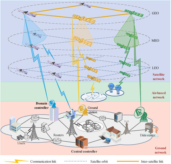
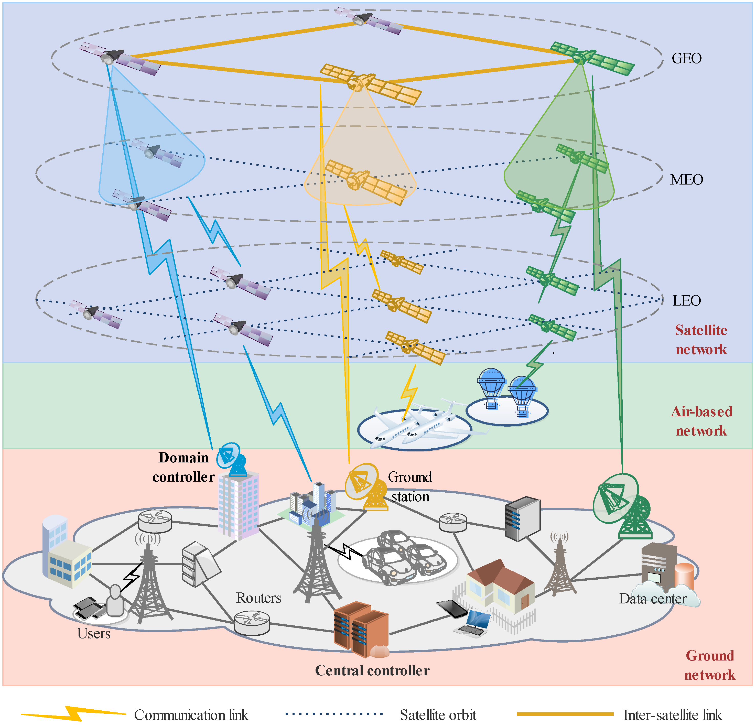
Figure 2 shows the hierarchical domain-based SDN-enabled space–air–ground integration network model adopted in this paper; the controller plane mainly consists of a multi-domain controller and central controller deployed near the gateway station. The data plane mainly consists of LEO satellites (Walker constellation Iridium constellation et al.), MEO satellites, GEO satellites and ground network nodes. Each group of domain controllers is responsible for the communication tasks of its own domain. Only when there is a cross-domain communication task will it send a request to the central controller, and the hierarchical and domain-divided network design pattern reduces the time of synchronous information consumption between controllers and increases the flexibility of controller expansion. The next problems to be solved are how to divide the network nodes into domains, how to deploy the controller, and how to make the satellite switch migration strategy due to the satellite network dynamics.
Figure 2.
Hierarchical SDN-enabled 6G SAGIN architecture.
2.1.1. Problem Description
In SDN-based satellite networks, due to the dynamic changes of network traffic and network topology and unreasonable deployment of SDN controllers seriously affecting the performance of SDN controllers, a load imbalance is caused in the controllers. The overload or idle state of the controller leads to a decrease in server resource utilization. Furthermore, the unreasonable network partition also leads to an increase in network delay and a decrease in network throughput. The satellite always moves along a particular orbit, and its topology changes periodically and highly dynamic during the system cycle. In the study of the optimal deployment of multi-controllers, a highly dynamic topology is planned as a system cycle by using the idea of time slice partition, and it is decomposed into several small time slices. It is assumed that the satellite network topology does not change in the time slice. With the change in time slice, the corresponding switch node migration strategy is made.
In the research of SDN-based multi-controller deployment for satellite networks, the problem that should be solved is how to divide the network reasonably and to determine the relationship between the controller and switch node. That is, the multi-controller deployment problem can be transformed into a task assignment problem by assigning a task to a target object in order to achieve the overall optimal goal.
2.1.2. Hierarchical Multi-Controller Deployment Modeling
The SDN-based satellite network model is abstracted into an undirected graph with three dimensions, expressed by , where S is the set of switches , and there are n switch nodes in total. C is the set of controllers , there are n controller nodes in total, E is the communication link between the switch node and the controller , where , one is the communication link available, and zero is the broken link. In this paper, the delay and the load of the controller are taken as the indicators of the multi-controller deployment strategy, in which the delay refers to the propagation delay from the switch node to the controller, since the switch sends packet-IN packets to the controller in real time over the SDN network, and the load of the controller is measured by the number of packet-IN packet requests per unit time.
Network Delay Model
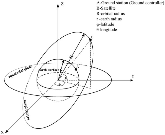
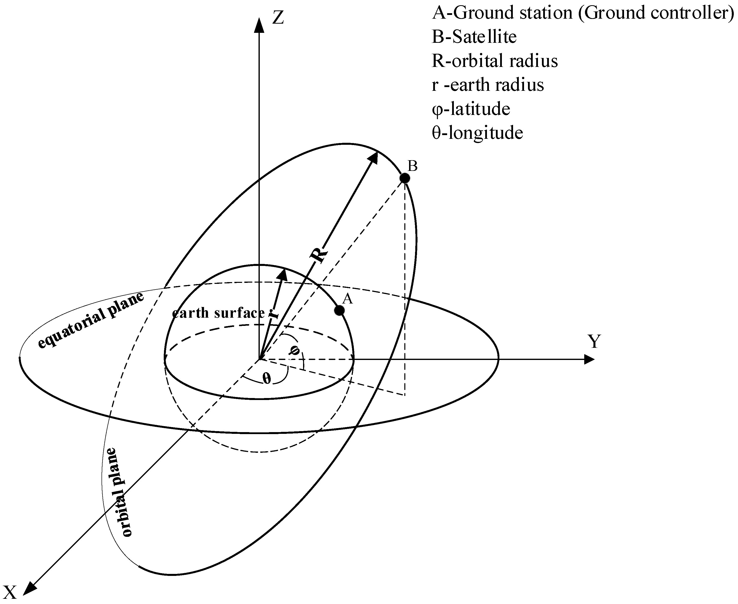
The propagation delay between the switch and the controller is the distance between two points in space divided by the speed of light. The propagation delay unit is ms. Let the known data be the longitude, latitude and altitude information of the satellite node and controller, as shown in Figure 3.
Figure 3.
The 3D coordinate diagram of the satellite operation.
Assuming that point A is the latitude and longitude of a controller , and point B is the latitude and longitude of a satellite node , first convert the geographical coordinates into three-dimensional Cartesian coordinates by using (1) and (2):
where R is the radius of the orbit and r is the radius of the Earth; theoretically, , and h is the altitude of the satellite. Then, the distance between A and B is (Equation (3)):
Finally, the propagation delay from the switch to the controller in t time chip is expressed by using (4):
where represents the speed of light m/s. In addition, because the satellite node is dynamic, set a maximum delay ; when the satellite switch node is not in the jurisdiction of the current controller.
The above analysis leads to the optimization of sub-goal 1 as follows: (Equation (5)):
Controller Load Model
There are three main considerations for controller load: number of the packet-IN packet requests to the controller, memory load , and CPU load . If the packet-IN packet rate of the switch node is , the controller load for time slice t is expressed by using (6):
where is the set of switch nodes governed by the controller , is the resource capacity of the controller , and is the variable parameter [34]. In addition, the maximum resource capacity of the controller is , when , which means that the current controller cannot move into the switch node, and is a variable parameter.
In order to achieve load balance among the controllers, the optimization sub-goal is defined as minimizing the variance of the controller load. The physical meaning of variance is to measure the deviation between the random variable and its mathematical expectation (i.e., the mean); thus, the variance can be used to measure whether the controllers are in equilibrium with each other. The above analysis leads to the optimization of sub-goal 2 as follows (Equation (7)):
Loss Function
The existence of the loss function is mainly used to determine whether to update the position coordinates of the controller and the relationship between the switch and the controller. The loss function is defined as the weighted sum of the maximum delay of the network and the total average load of the controller. The formula is as follows (Equation (8)):
where is the weight of the delay and load, variable parameters, and is the maximum load.
To sum up, the packet-IN packet rate and transmission delay of switch nodes are optimized by multi-objective optimization. The resulting multi-objective optimization function is described as follows (Equation (9)):
The solution space X is the controller position matrix and the corresponding relation matrix between the switch and the controller.
The objective function condition is described as follows:
- Condition 1: Communication link status of switch and controller: .
- Condition 2: The number of controllers is greater than 2.
- Condition 3: The controller to the jurisdiction of the switch node delay is less than the maximum delay: .
- Condition 4: Controller resource capacity greater than 0: .
- The solution space, i.e., the latitude and longitude of the controller is limited in China (latitude: 3.86–53.55°; longitude: 73.66–135.05°).
2.2. Problem Solution
Multi-Controller Deployment Algorithm Based on Simulated Annealing
In order to find the global optimal solution of the optimization model, avoid falling into the local optimal solution, flexibly control the iteration speed, and quickly obtain the global optimal solution, this strategy draws on the idea of a simulated annealing algorithm, accepts the poor solution space with a certain probability, and presents the local optimal solution. The next solution space is randomly generated and has good robustness. The cooling rate is controllable, and the search results can be obtained faster.
The pseudo-code of Algorithm 1 outlines the framework of the multi-controller deployment strategy. The inputs include the controller (ground station) longitude and latitude matrix C, satellite longitude and latitude matrix S, height matrix , traffic of switch nodes , and the maximum controller capacity . The initialization parameters include the relation matrix of the satellite corresponding controller R, initial temperature t, and descending speed step and final temperature e. First, the data plane, that is, the satellite node latitude and longitude data, is transformed into the Cartesian coordinate data by Formula (1). Then, after a certain number of iterations, the temperature is increased. In the next iteration, the following is carried out:
- First, a new solution space is randomly generated, which is the controller’s new latitude and longitude, and is converted to Cartesian coordinates according to Formula (2).
- Second, the propagation delay from the satellite node to the controller is solved according to Formula (3).
- In the third step, the satellite node is assigned to the target controller with the goal of minimum time delay, and then the load of the controller is calculated; if a controller load is greater than times the maximum load, the part of the controller controlled by the current controller is transferred to the controller with the least load, and the relation matrix R between the satellite node and the controller is obtained.
Finally, the relation matrix R, and the solution space, i.e., the final latitude and longitude of the controller, the propagation delay and the load of the controller are saved.
where is the probability of accepting the current solution space, is the loss value of the current iteration, is the loss value of the previous iteration, and t is the rate at which the temperature decreases.
| Algorithm 1 Multi-controller deployment algorithm based on simulated annealing. |
| Input: Controller(Ground station) longitude and latitude matrix C, Satellite longitude and latitude matrix S, height matrix , Traffic of switch nodes , and the maximum controller capacity . |
| Output: Number of controllers and longitude and latitude matrix , relation matrix of satellite corresponding controller R, propagation delay L and controller load B. |
| 1: Initialize The relation matrix of the satellite corresponding controller is R, initial temperature t, descending speed and final temperature e. |
| 2: |
| 3: while do |
| 4: for do |
| 5: |
| 6: |
| 7: |
| 8: |
| 9: |
| 10: |
| 11: |
| 12: if or |
| 13: then |
| 14: |
| 15: |
| 16: end if |
| 17: end for |
| 18: |
| 19: |
| 20: end while |
2.3. Switch Node Migration Strategy for Controller Load Balancing
Because the satellite constellation moves periodically, the load of the controller will be out of balance with the change in time slice, so it is necessary to trigger the node migration of the switch in order to achieve load balance among the controllers. A pseudo-code description of the migration strategy is given below as Algorithm 2.
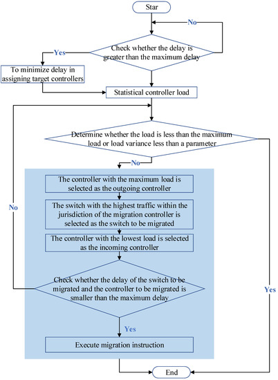
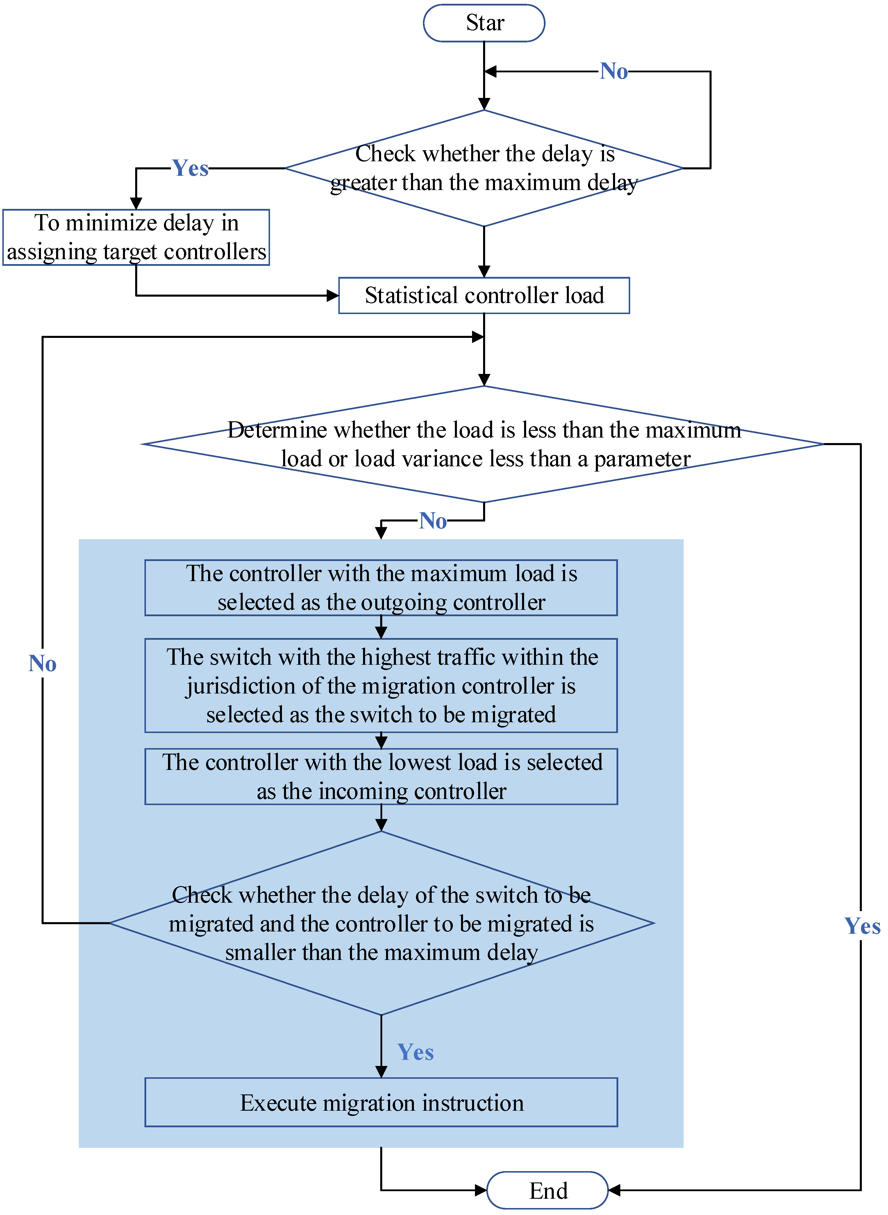
When the relation matrix is updated in the seventh step, the propagation delay between the switch and the controller is less than the maximum propagation delay, and the switch node is not migrated; then, the load of the controller is considered, and a migration strategy is made. Figure 4 shows the flowchart of the switch migration policy.
| Algorithm 2 Switch node migration strategy for controller load balancing. |
| Input: The longitude and latitude matrix C of the controller(ground station) is obtained by Algorithm 1, The satellite longitude and latitude matrix S and height matrix of 100 time slices, packet-IN flow of switch nodes and the maximum capacity of the controller increasing linearly with time slices. |
| Output: The time slice T, the average propagation delay L, the relation matrix R of the satellite corresponding to the controller, and the load of the controller. |
| 1: |
| 2: for do |
| 3: |
| 4: |
| 5: |
| 6: |
| 7: |
| 8: |
| 9: end for |
Figure 4.
Flow chart of switch migration policy.
First, the process begins to input the delay from all switches to all controllers, and determines whether there is a switch node that is larger than the maximum propagation delay, and if there is a target controller that is reallocated to minimize the propagation delay; if it does not exist, all switches are judged to be bad. In the next step, according to the relation matrix obtained in the previous step, the load of the controller is counted, and then it is judged whether the controller achieves load balance: one is all the controller load less than 85% of the maximum load, and the other is to find out the variance of all the controller load, to determine whether the variance is less than a parameter (according to the specific experimental settings). If the condition that the controller satisfies the load balance is satisfied, the calculation of the next time slice is finished. If the load balance condition is not satisfied, the switching strategy is started. Firstly, the controller with the largest load is selected as the outgoing controller, and the switch with the largest load is selected as the outgoing switch; then, the minimum load controller is selected as the immigration controller, and then the propagation delay between the switch to be migrated and the immigration controller is determined to be less than the maximum propagation delay, and the switch migration is completed by the cooperation of the out-and-in controller and the in–out controller. Otherwise, the switch is cycled until the load balance is achieved. Finally, the program ends by returning the relational matrix and the controller load.
2.4. Algorithm Complexity Analysis
Firstly, considering the time complexity analysis of Algorithm 1 (multi-controller deployment strategy based on the simulated annealing algorithm), the algorithm is the outermost cycle of the temperature drop T, each temperature K iteration, each iteration process N switch, and M controllers; the time complexity is therefore . For Algorithm 2, each time slice handles N switches and M controllers at a time, so the algorithm complexity is .
Secondly, for the space complexity, Algorithm 1 needs to update the control deployment information N, the delay matrix , the relation matrix and the loss function value, so the space complexity is . For Algorithm 2, the relational matrix and the controller load need to be stored so the controller complexity is also .
3. Results
3.1. Experimental Scene Description
The iridium constellation network is used as the data surface of SDN in the simulation scene, and the controller is deployed at the ground gateway station. The iridium constellation consists of 66 working satellites in six polar circular orbits, that is, 11 in-orbit satellites in each orbit plane, separated by an interval of about 4500 km. The satellites are located in low-earth polar orbit 780 km above the Earth and orbit the Earth once every 100 min at a speed of 27,070 km per hour. The constellations are shown in Table 1.
Table 1.
Iridium system parameters.
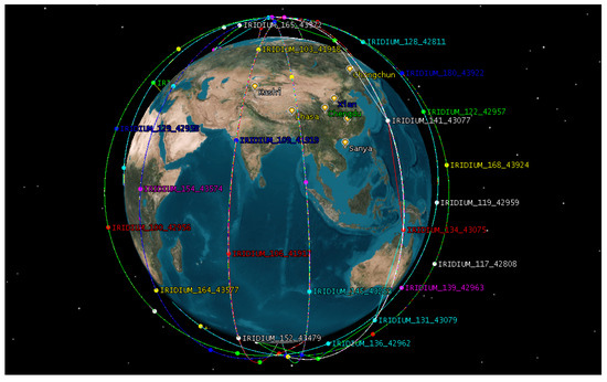
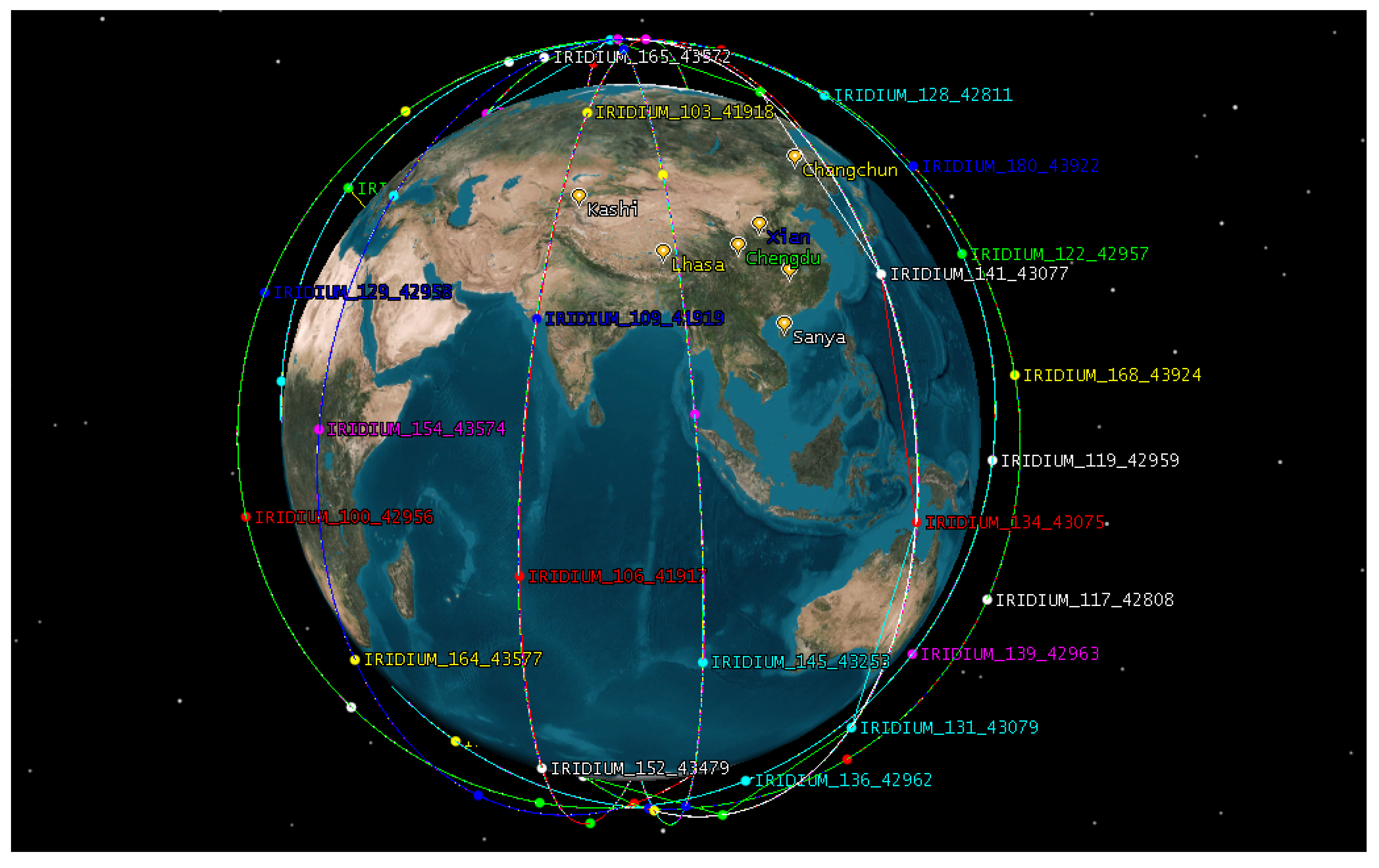
The data source is from STK (Systems Tool Kit), which collects the latitude and longitude of satellite nodes and the altitude, latitude and longitude of the ground station. The iridium satellite system’s satellite cycle is about 100 min, the length of each time slice is set to 1 min, and the satellite constellation’s operating cycle will be divided into 100 time slices. The iridium constellation network topology generated by STK software is shown in Figure 5.
Figure 5.
Iridium system network.
The other parameters are as follows: a single controller can handle up to 60,000 packet-IN request packets, that is, , and is 0.85. The switch switchover occurs when the load reaches 85% of the server load to achieve load balancing. The weight ratio of load factor is . The maximum propagation delay from the satellite node to the controller is ms. The weight ratio of propagation delay to load is .
3.2. Result Analysis
3.2.1. In the Case of Different Number of Controllers, the Load of Each Controller and the Maximum Propagation Delay from the Switch Node to the Controller Are Calculated
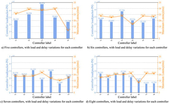
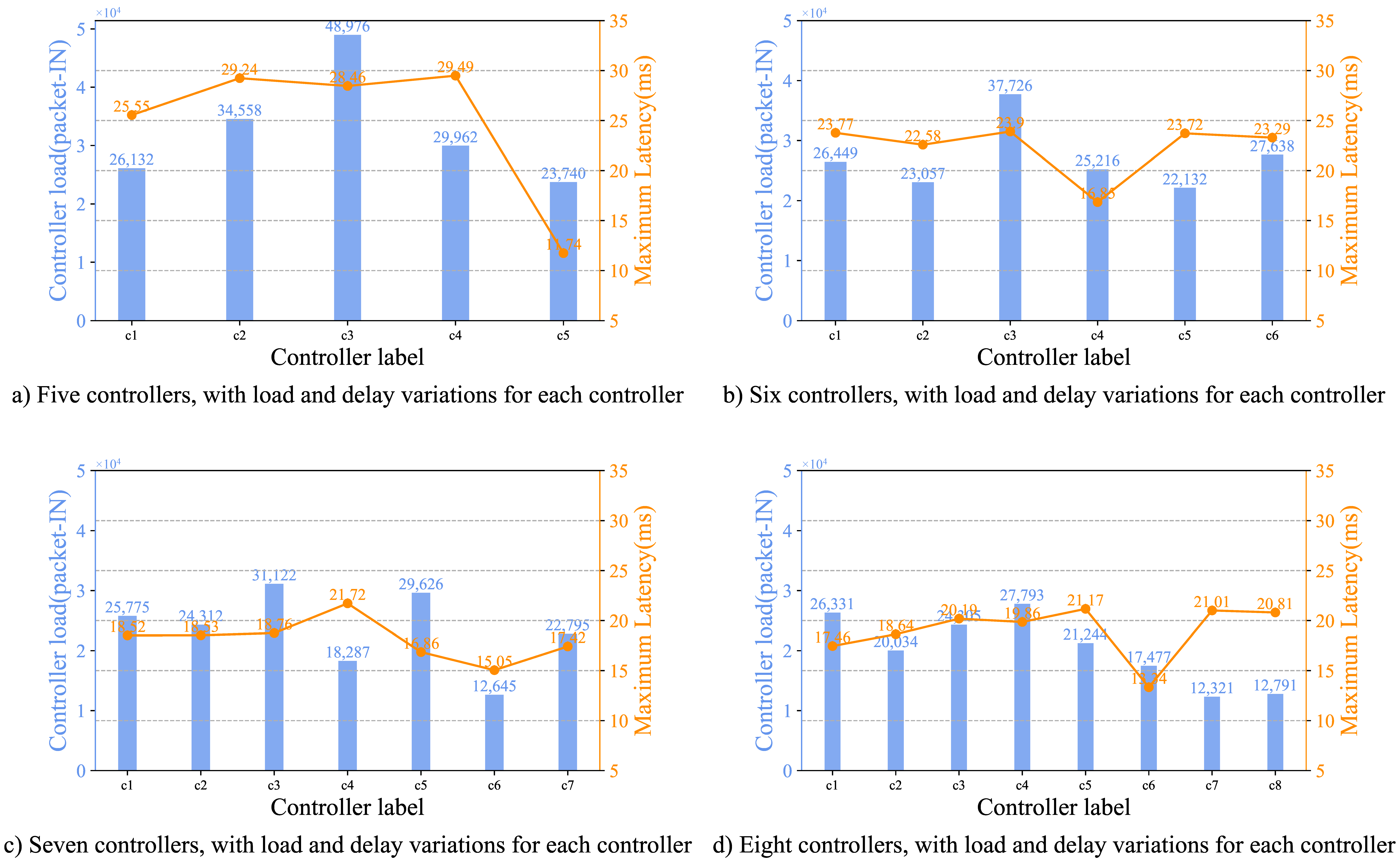
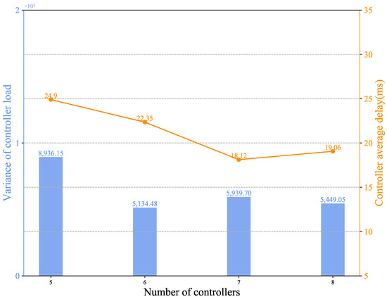
As shown in Figure 6 (to visualize how the controller handles packet-in, where the load indicates the packet-in packet received by the controller), each subgraph represents the current number of controllers, changes in load and maximum propagation delay for each controller. With the increase in the number of controllers, the maximum propagation delay from the switch to the controller decreases, and the load difference between the controllers decreases, in order to better analyze the relationship between the load and the propagation delay and the number of controllers, the graph of the relationship between the number of controllers and the variance and average delay of the controller load is given in Figure 7.
Figure 6.
Diagram of delay and load variation for each controller.
Figure 7.
Diagram of the number of controllers and the variation of load variance and delay.
Through the analysis of the graph above, the average delay of the whole network shows a downward trend with the increase in the number of controllers, which is in line with our theoretical formula, but combined with the analysis of the load value, the load of the six controllers is the best at the time of load; however, the propagation delay is not optimal at this time. When the transmission delay changes from seven controllers to eight controllers, the load decreases, but the delay increases. This is also in line with our theoretical derivation, and the number of controllers can be determined according to the minimum required delay and the optimal load. If the minimum propagation delay is less than 20 (ms), the number of controllers can be determined according to the minimum required delay and load; if the controller load variance is less than 6000, you can choose seven controllers.
3.2.2. The Controller Load Varies with the Packet-In Request Packet of the Switch
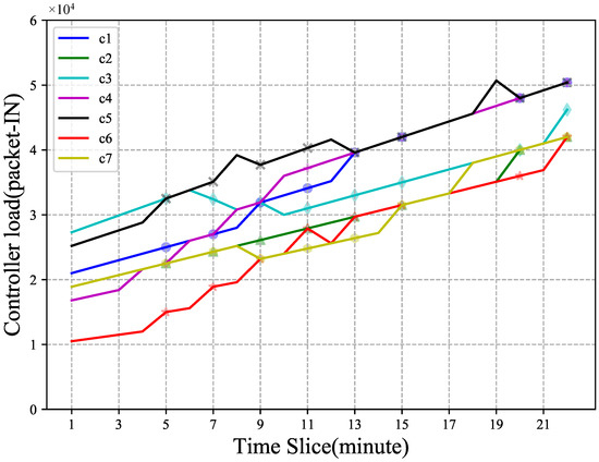
To better analyze the switching process, the packet-IN request packets of the switch node are linearly increased by 100 packets per time slice in a simulation. On the basis of the first experiment, after reaching the optimal number and position of controller deployment, Algorithm 2 should be run once per time slice. The simulation results show that the controller load changes linearly with packet-IN request packets (time slice). The results of the simulation are shown in Figure 8.
Figure 8.
Diagram of controller load versus time slice.
Due to the linear growth of switch traffic with time slice, the controller load also shows a linear growth trend. The position of the curvilinear punctuation marks the time slice in which the switch node migration occurs, where the time slice {5–12} is due to the variance of all controller loads greater than 6000 (packet-IN), leading to the switch node migration, and the time slice {17,19,20} is migrated by 85% of the switch nodes with C2 and C7 loads greater than the maximum load. The specific information is shown in Table 2.
Table 2.
Switch migration information.
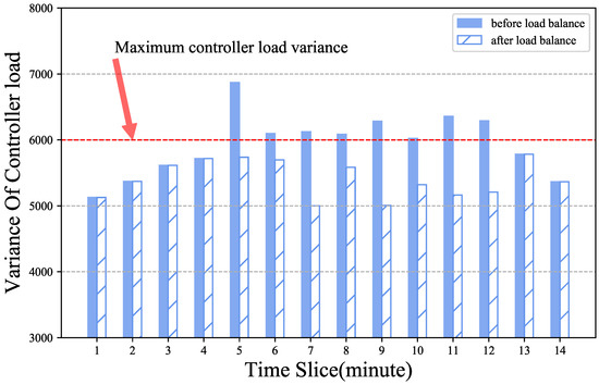
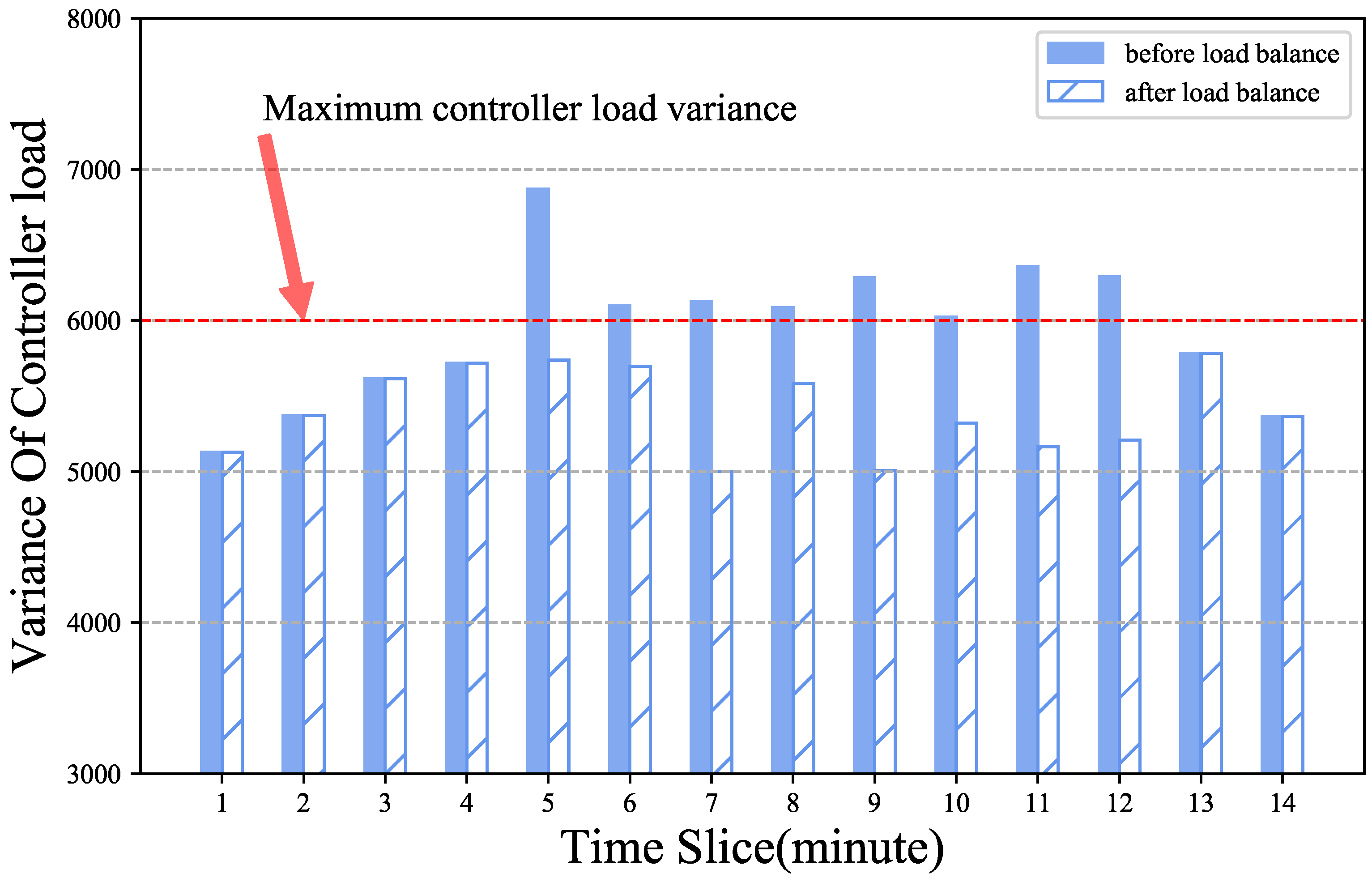
Figure 9 shows the change in controller load variance before and after switch migration. In order to show the simulation effect better, the results show the change of the first 14 time slices. As can be seen from the diagram, the variance of the controller load increases with the time slice from 1 to 4. 5 to 12 time slices, controller load variance over 6000, triggered switch migration, and with controller load variance that decreased significantly. After the 13th time slice, the controller load variance decreases gradually, and no switch migration occurs.
Figure 9.
Variation of controller load variance before and after switch migration.
3.2.3. Compare the Load Variances of Different Algorithms with Time
In this contrast experiment, OCLDS [26] and n-k-means [31] were selected as the contrast experiments; the former divides the load into four states, with a switch migration strategy, and the latter has no migration strategy. Each time slice requires an algorithm to be run to redistribute the relationship between the switch and the controller.
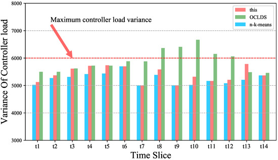
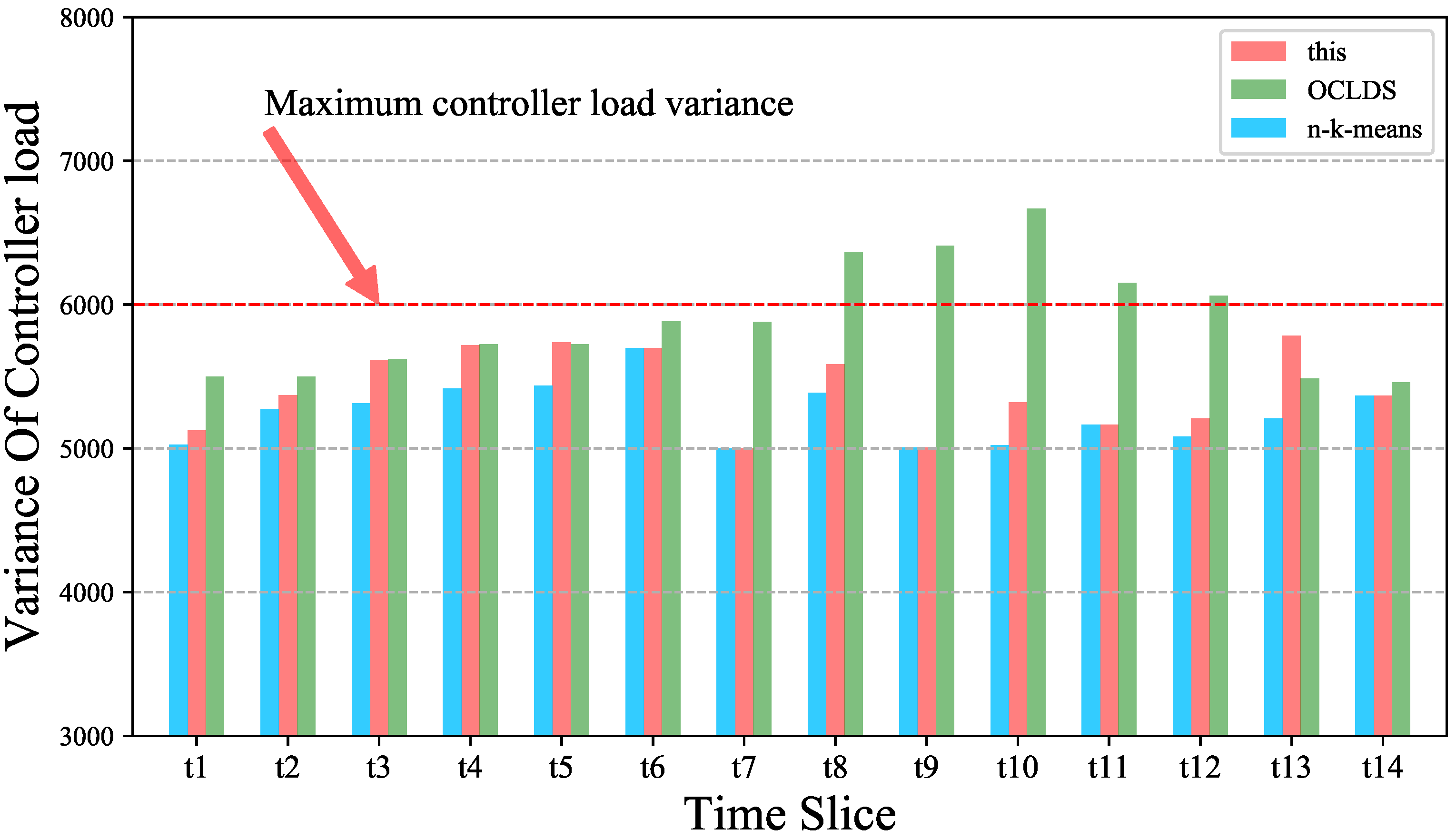
As shown in Figure 10, this strategy is compared with the other two algorithms in terms of controller load variance. First, the size of the comparison is obviously the best result obtained by the n-k-means strategy, and the load variance of the first 14 time-slice controllers does not change much. The main reason for this is that each time slice needs to re-execute the algorithm and re-distribute the relationship between the switch and the controller. Although this result is the best, it takes so long that there is not enough time to complete the switch migration before the next time slice starts. Secondly, as the analysis above, the switch migration occurs from the fifth time slice, and the controller load variance is equal to n-k-means, which is better than the OCLDS algorithm, and the controller load variance obtained by this strategy and OCLDS is increased first and then decreased, but the latter is delayed by several time slices. The reason for this is that the switch migration is restricted by the controller load variance and 85% of the maximum controller load, while OCLDS only controls the switch migration by the controller load segmentation; therefore, the performance of this strategy is improved by about 7.71% compared to OCLDS (calculated here by averaging the difference between the two time slices). Finally, because this strategy and OCLDS have developed a strategy to trigger the switch migration, it takes less time to complete the migration before the next time slice than the redistribution of n-k-means.
Figure 10.
Variation of controller load variance with time slice for different algorithms.
3.2.4. Compared with Different Algorithms, the Running Time of the Migration Algorithm Changes with the Increase in Switch Nodes
In addition to the 66 polar-orbiting satellites in the iridium constellation, the switch node uses the satellite data from the Starlink program and in turn uses STK to simulate the four Walker constellations (inclined orbits), a hybrid orbital constellation model (inclined and polar orbits) with the parameters in Table 3.
Table 3.
Detailed parameters for different constellations.
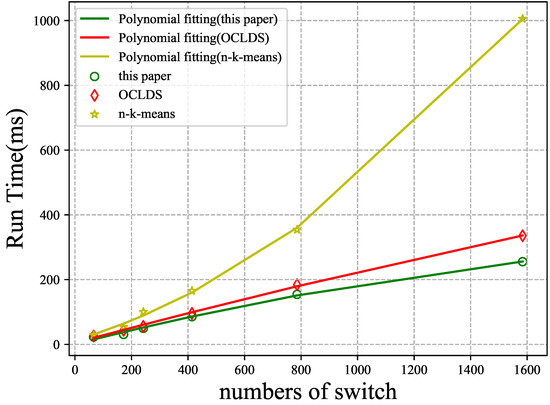
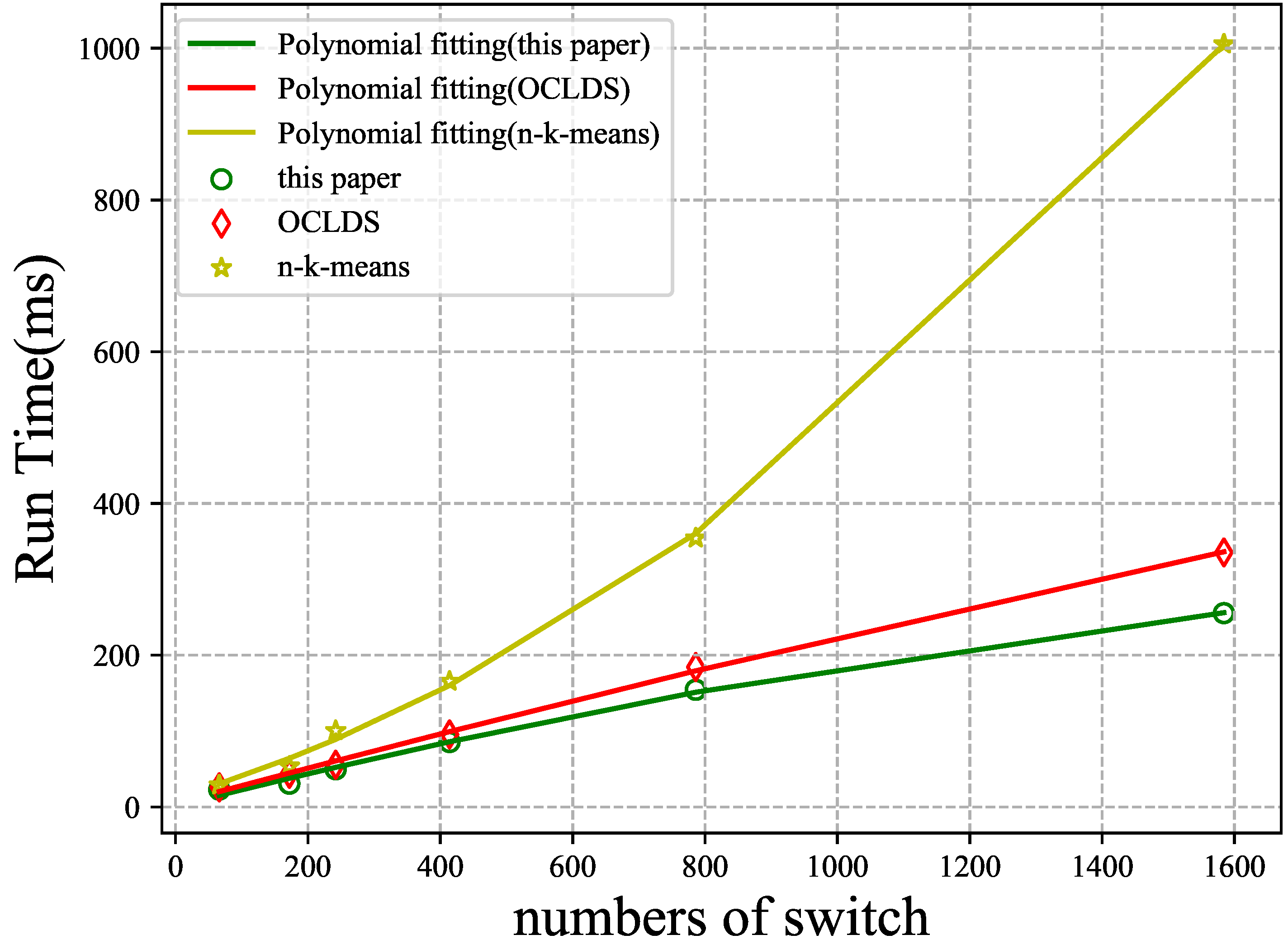
As shown in Figure 11, the scattered points represent the number of nodes corresponding to the algorithm running time and running time of the calculation: the information of a cycle of each time slice of the running time is given as the average value. The curve represents the polynomial fitting of scattered points, and the running time of the three algorithms increases with the number of nodes. According to the time complexity analysis, the migration strategy of this paper and OCLDS is O(m), so the fitting curve shows a linear increasing trend. The time complexity of n-k-means is approximately O(n * m), where m is the number of controllers and n is the node of switches. In addition, when the number of nodes exceeds 1000, n-k-means uses more than half of a time slice to figure out the migration strategy, and it is highly likely that the controller fails to complete the migration within a time slice. The other two strategies are significantly faster than n-k-means.
Figure 11.
The running times of different algorithms vary with the number of switch nodes.
4. Conclusions
Aiming to solve the problems of a large number of nodes and dynamic changes in the network topology of the SDN-based hierarchical space–air–ground integrated network scenario, this paper first constructs a delay model, a load model, and a loss function model. The loss function model is defined by two factors, namely the propagation delay from the controller to the switch node and the load of the controller. Then, a multi-control deployment strategy based on simulated annealing is proposed, and a strategy for dynamic switch migration with the change in time slice is proposed. In the multi-control deployment strategy, the loss function is used as a measure of algorithm convergence. In the switch migration strategy, the introduction of the controller load variance is used as a condition for judging whether the controller load satisfies the balance. Finally, the experimental part of this paper compares and analyzes the changes in controller load and average delay under different numbers of controllers, and a specific deployment plan is given under the condition of specifying the maximum delay and maximum controller load. In addition, to verify the reliability of the switch migration strategy, a comparison experiment before and after the switch migration load was also conducted. To verify the superiority of the algorithm, a comparison experiment was carried out with the two algorithms of n-k-means and OCLDS in terms of the load performance and running time of the controller, and the experimental data were all derived from reliable data simulated by STK. The results show that the algorithm in this paper improves the load performance of the controller by about 7.71% compared with the other two algorithms.
Our future work will introduce the vehicle and UAV into our SAGIN infrastructure [35], and discuss the mobile controller equipped on the vehicle and/or UAV to fulfill the service requirements from ground and space area.
Author Contributions
Conceptualization, C.C., Q.P. and Z.L.; methodology, C.C. and Z.L.; software, Z.L.; validation, C.H.; formal analysis, C.C.; investigation, J.J.; resources, C.C., C.H. and Z.L.; data curation, Y.J.; writing original draft preparation, Z.L.; supervision, C.C.; project administration, Q.P.; funding acquisition, C.H. and Q.P. All authors have read and agreed to the published version of the manuscript.
Funding
This work was supported by the National Key Research and Development Program of China (2020YFB1807500), the National Natural Science Foundation of China (62072360, 62001357, 61672131, 61901367), the key research and development plan of Shaanxi province (2021ZDLGY02-09, 2020JQ-844), the key laboratory of embedded system and service computing (Tongji University) (ESSCKF2019-05), Ministry of Education, Xi’an Science and Technology Plan (20RGZN0005) and the Xi’an Key Laboratory of Mobile Edge Computing and Security (201805052-ZD3CG36).
Institutional Review Board Statement
Not applicable.
Informed Consent Statement
Not applicable.
Data Availability Statement
The data presented in this study are available on request from the corresponding author.
Acknowledgments
These authors would like to thank the China Electronics Technology Group to provide some orbital statistics.
Conflicts of Interest
The authors declare no conflict of interest.
Abbreviations
The following abbreviations are used in this manuscript:
| SAGIN | Space–Air–Ground Integrated Network |
| LEO | Geosynchronous Earth Orbit |
| MEO | Medium Earth Orbit |
| LEO | Low Earth Orbit |
| VLEO | Very Low Earth Orbit |
| HAP | High-Altitude Platform |
| LAP | Low-Altitude Platform |
| UAV | Unmanned Aerial Vehicle |
| SDN | Software Defined Network |
| NFV | Network Function Virtualization |
| n-k-means | n times k-means |
| OCLDS | Optimizing Controller Load Dynamic Strategy |
| SAA | Simulated Annealing Algorithm |
| STK | Satellite Tool Kit |
References
- Latva-aho, M.; Leppänen, K.; Clazzer, F.; Munari, A. Key Drivers and Research Challenges for 6G Ubiquitous Wireless Intelligence; Electronic Library: Koln, Germany, 2020. [Google Scholar]
- Zhang, Z.; Ning, H.; Shi, F.; Farha, F.; Xu, Y.; Xu, J.; Zhang, F.; Choo, K.K.R. Artificial intelligence in cyber security: Research advances, challenges, and opportunities. Artif. Intell. Rev. 2021, 55, 1029–1053. [Google Scholar] [CrossRef] [Scilit]
- Liu, J.; Shi, Y.; Fadlullah, Z.M.; Kato, N. Space-Air-Ground Integrated Network: A Survey. IEEE Commun. Surv. Tutor. 2018, 20, 2714–2741. [Google Scholar] [CrossRef] [Scilit]
- Ray, P.P. A review on 6G for space-air-ground integrated network: Key enablers, open challenges, and future direction. J. King Saud-Univ.-Comput. Inf. Sci. 2021; in press. [CrossRef] [Scilit]
- Liu, L.; Chen, C.; Pei, Q.; Maharjan, S.; Zhang, Y. Vehicular edge computing and networking: A survey. Mob. Netw. Appl. 2021, 26, 1145–1168. [Google Scholar] [CrossRef] [Scilit]
- Cong, W.; Chen, C.; Qingqi, P.; Zhiyuan, J.; Shugong, X. An Information Centric In-network Caching Scheme for 5G-Enabled Internet of Connected Vehicles. IEEE Trans. Mob. Comput. 2021; in press. [CrossRef] [Scilit]
- Wan, S.; Ding, S.; Chen, C. Edge computing enabled video segmentation for real-time traffic monitoring in internet of vehicles. Pattern Recognit. 2022, 121, 108146. [Google Scholar] [CrossRef] [Scilit]
- Ma, J.; Li, T.; Cui, J.; Ying, Z.; Cheng, J. Attribute-based secure announcement sharing among vehicles using blockchain. IEEE Internet Things J. 2021, 8, 10873–10883. [Google Scholar] [CrossRef] [Scilit]
- Kato, N.; Fadlullah, Z.M.; Tang, F.; Mao, B.; Tani, S.; Okamura, A.; Liu, J. Optimizing space-air-ground integrated networks by artificial intelligence. IEEE Wirel. Commun. 2019, 26, 140–147. [Google Scholar] [CrossRef] [Scilit]
- Wei, D.; Ning, H.; Shi, F.; Wan, Y.; Xu, J.; Yang, S.; Zhu, L. Dataflow management in the internet of things: Sensing, control, and security. Tsinghua Sci. Technol. 2021, 26, 918–930. [Google Scholar] [CrossRef] [Scilit]
- Cheng, N.; Quan, W.; Shi, W.; Wu, H.; Ye, Q.; Zhou, H.; Zhuang, W.; Shen, X.; Bai, B. A comprehensive simulation platform for space-air-ground integrated network. IEEE Wirel. Commun. 2020, 27, 178–185. [Google Scholar] [CrossRef] [Scilit]
- Gao, H.; Liu, C.; Yin, Y.; Xu, Y.; Li, Y. A hybrid approach to trust node assessment and management for vanets cooperative data communication: Historical interaction perspective. IEEE Trans. Intell. Transp. Syst. 2021; in press. [CrossRef] [Scilit]
- Fu, S.; Ma, L.; Atiquzzaman, M.; Lee, Y.J. Architecture and performance of SIGMA: A seamless mobility architecture for data networks. In Proceedings of the IEEE International Conference on Communications, ICC 2005, Seoul, Korea, 16–20 May 2005; Volume 5, pp. 3249–3253. [Google Scholar]
- Zhao, Y.; Zhai, W.; Zhao, J.; Zhang, T.; Sun, S.; Niyato, D.; Lam, K.Y. A comprehensive survey of 6g wireless communications. arXiv 2020, arXiv:2101.03889. [Google Scholar]
- Shi, Y.; Cao, Y.; Liu, J.; Kato, N. A cross-domain SDN architecture for multi-layered space-terrestrial integrated networks. IEEE Netw. 2019, 33, 29–35. [Google Scholar] [CrossRef] [Scilit]
- Ye, J.; Dang, S.; Shihada, B.; Alouini, M.S. Space-air-ground integrated networks: Outage performance analysis. IEEE Trans. Wirel. Commun. 2020, 19, 7897–7912. [Google Scholar] [CrossRef] [Scilit]
- Mozaffari, M.; Lin, X.; Hayes, S. Towards 6G with Connected Sky: UAVs and Beyond. arXiv 2021, arXiv:2103.01143. [Google Scholar] [CrossRef] [Scilit]
- Qiu, T.; Zhang, S.; Si, W.; Cao, Q.; Atiquzzaman, M. A 3-D Topology Evolution Scheme with Self-Adaption for Industrial Internet of Things. IEEE Internet Things J. 2020, 8, 9473–9483. [Google Scholar] [CrossRef] [Scilit]
- Guo, Y.; Li, Q.; Li, Y.; Zhang, N.; Wang, S. Service Coordination in the Space-Air-Ground Integrated Network. IEEE Netw. 2021, 35, 168–173. [Google Scholar] [CrossRef] [Scilit]
- Qiu, T.; Wang, X.; Chen, C.; Atiquzzaman, M.; Liu, L. TMED: A spider-Web-like transmission mechanism for emergency data in vehicular ad hoc networks. IEEE Trans. Veh. Technol. 2018, 67, 8682–8694. [Google Scholar] [CrossRef] [Scilit]
- Zhang, N.; Zhang, S.; Yang, P.; Alhussein, O.; Zhuang, W.; Shen, X.S. Software defined space-air-ground integrated vehicular networks: Challenges and solutions. IEEE Commun. Mag. 2017, 55, 101–109. [Google Scholar] [CrossRef] [Scilit]
- Shirmarz, A.; Ghaffari, A. Taxonomy of controller placement problem (CPP) optimization in Software Defined Network (SDN): A survey. J. Ambient. Intell. Humaniz. Comput. 2021, 12, 10473–10498. [Google Scholar] [CrossRef] [Scilit]
- Tian, X.; Shen, H.; Chen, X.; Li, C. Analysis of SDN Multi-controller Placement. In 2020 International Conference on Data Processing Techniques and Applications for Cyber-Physical Systems; Springer: Singapore, 2021; pp. 677–684. [Google Scholar]
- Chen, C.; Jiange, J.; Rufei, F.; Lanlan, C.; Cong, L.; Shaohua, W. An Intelligent Caching Strategy Considering Time-space Characteristics in Vehicular NamedData Networks. IEEE Trans. Intell. Transp. Syst. 2021; in press. [CrossRef] [Scilit]
- Wu, H.; Chen, J.; Zhou, C.; Shi, W.; Cheng, N.; Xu, W.; Zhuang, W.; Shen, X.S. Resource management in space-air-ground integrated vehicular networks: SDN control and AI algorithm design. IEEE Wirel. Commun. 2020, 27, 52–60. [Google Scholar] [CrossRef] [Scilit]
- Wei, D.; Wei, N.; Yang, L.; Kong, Z. SDN-based multi-controller optimization deployment strategy for satellite network. In Proceedings of the 2020 IEEE International Conference on Power, Intelligent Computing and Systems (ICPICS), Shenyang, China, 28–30 July 2020; pp. 467–473. [Google Scholar]
- Kumari, A.; Sairam, A.S. A survey of controller placement problem in software defined networks. arXiv 2019, arXiv:1905.04649. [Google Scholar]
- Yan, B.; Liu, Q.; Shen, J.; Liang, D.; Zhao, B.; Ouyang, L. A survey of low-latency transmission strategies in software defined networking. Comput. Sci. Rev. 2021, 40, 100386. [Google Scholar] [CrossRef] [Scilit]
- Semong, T.; Maupong, T.; Anokye, S.; Kehulakae, K.; Dimakatso, S.; Boipelo, G.; Sarefo, S. Intelligent load balancing techniques in software defined networks: A survey. Electronics 2020, 9, 1091. [Google Scholar] [CrossRef] [Scilit]
- Mostafaei, H.; Menth, M.; Obaidat, M.S. A learning automaton-based controller placement algorithm for software-defined networks. In Proceedings of the 2018 IEEE Global Communications Conference (GLOBECOM), Abu Dhabi, United Arab Emirates, 9–13 December 2018; pp. 1–6. [Google Scholar]
- Qu, H.; Xu, X.; Zhao, J.; Yue, P. An SDN-Based Space-Air-Ground Integrated Network Architecture and Controller Deployment Strategy. In Proceedings of the 2020 IEEE 3rd International Conference on Computer and Communication Engineering Technology (CCET), Beijing, China, 14–16 August 2020; pp. 138–142. [Google Scholar]
- Qi, Y.; Wang, D.; Yao, W.; Li, H.; Cao, Y. Towards multi-controller placement for SDN based on density peaks clustering. In Proceedings of the ICC 2019-2019 IEEE International Conference on Communications (ICC), Shanghai, China, 20–24 May 2019; pp. 1–6. [Google Scholar]
- Tao, P.; Ying, C.; Sun, Z.; Tan, S.; Wang, P.; Sun, Z. The controller placement of software-defined networks based on minimum delay and load balancing. In Proceedings of the 2018 IEEE 16th Intl Conf on Dependable, Autonomic and Secure Computing, 16th Intl Conf on Pervasive Intelligence and Computing, 4th Intl Conf on Big Data Intelligence and Computing and Cyber Science and Technology Congress (DASC/PiCom/DataCom/CyberSciTech), Athens, Greece, 12–15 August 2018; pp. 310–313.
- Cheng, J.; Yuan, G.; Zhou, M.; Gao, S.; Liu, C.; Jiang, C. A Fluid Mechanics-Based Model to Estimate VINET Capacity in an Urban Scene. IEEE Trans. Intell. Transp. Syst. 2021; in press. [CrossRef] [Scilit]
- Chen, C.; Liu, L.; Wan, S.; Hui, X.; Pei, Q. Data Dissemination for Industry 4.0 Applications in Internet of Vehicles Based on Short-term Traffic Prediction. ACM Trans. Internet Technol. (TOIT) 2021, 22, 1–18. [Google Scholar] [CrossRef] [Scilit]

Publisher’s Note: MDPI stays neutral with regard to jurisdictional claims in published maps and institutional affiliations. |
© 2022 by the authors. Licensee MDPI, Basel, Switzerland. This article is an open access article distributed under the terms and conditions of the Creative Commons Attribution (CC BY) license (https://creativecommons.org/licenses/by/4.0/).