1. Introduction
The purpose of dense semantic Simultaneous Localization and Mapping (SLAM) is to locate the robots and reconstruct a dense 3D semantic map simultaneously. Geometric information is important for robots to navigate safely in unknown, unstructured, real-world environments, while semantic information provides the higher-level information of robotic perception to understand and execute human instructions, such as “go to the computer” or “find the wallet”. Although there are many methods in geometric reconstruction, such as Structure from Motion (SfM) [
1], Multi-View Stereo (MVS) [
2] and SLAM [
3], semantic segmentation methods based on deep learning (DL), such as [
4,
5,
6], have not intersected with geometric reconstruction for a long time. In recent years, however, there has been a growing interest towards research and applications towards the combination of geometric reconstruction and DL-based semantic segmentation [
3,
7,
8,
9,
10]. As far as we know, most dense semantic SLAM methods such as [
11,
12] require GPU acceleration. Some other methods such as Kimera [
13] have achieved dense semantic SLAM without GPU, but they execute semantic segmentation offline, and cannot be classified as dense semantic SLAM strictly. In recent years, Unmanned Aerial Vehicles (UAVs) have been widely used, but they are always with limited computing resources. Existing dense semantic SLAM methods limit the use of the intelligent navigation on UAVs. However, an intelligent UAV is essential in some scenes, such as exploring dangerous buildings. Therefore, achieving dense semantic SLAM with limited computing resources is necessary.
On the spur of the growing interest in dense semantic SLAM and the widespread use of UAVs, a dense semantic SLAM system for indoor environment using CPU computing named CDSFusion is presented in this paper. Compared to most efforts for only Visual-Inertial Odometry (VIO) or 3D semantic reconstruction, CDSFusion combines the works in two regions. The proposed method has the ability to localize the UAV and perform dense semantic 3D reconstruction simultaneously on a CPU. We are also interested in robustness, accuracy and efficiency of the system. The VIO of CDSFusion is based on the state-of-the-art VINS-Mono [
14], and the depth information given by a RGBD camera was introduced to improve the robustness and accuracy of the system. The FAST [
15] features were adapted to improve the efficiency of pose estimation instead of the Shi-Tomasi [
16] features used in VINS-Mono. The semantic segmentation results were gained by the PSPNet (Pyramid Scene Parsing Network) [
5], and the OpenVINO was used to optimize the pre-trained model for faster inference. A dense semantic model was constructed by the lightweight 3D reconstruction method—Voxblox [
17]. CDSFusion is designed with modularity and has three key modules: an RGBD-based VIO module for pose estimation, an optimized lightweight semantic segmentation module for real-time segmentation and a 3D reconstruction module integrating semantic information for model generation. Therefore, the proposed method is modular and allows replacing each module or executing them in isolation. For instance, CDSFusion can easily fall back to a fast, robust, and accurate VIO, a lightweight semantic segmentation solution, or a dense 3D reconstruction method.
Therefore, we can summarize the main contributions of our work as follows:
A visual-inertial odometry for fast, highly accurate and globally consistent trajectory estimate. Our VIO is based on VINS-Mono, introducing the depth information to obtain a precise scale, and FAST features were used instead of Shi-Tomasi features to obtain faster feature tracking;
A lightweight dense semantic fusion method working on a CPU. The 3D point clouds were fused using Voxblox, and semantically annotated the 3D point clouds using 2D pixel-wise semantic segmentation. The semantic information was given by the optimized PSPNet pre-trained model;
A complete lightweight dense semantic SLAM system working only on a CPU. Using consistent pose and semantic information, the components are organically combined to improve the operation efficiency of the system on a CPU while ensuring the localization and reconstruction accuracy.
The remainder of this paper is organized as follows:
Section 2 introduces the related methods;
Section 3 introduces an overview of the proposed method, and the details of the building blocks are described in subsections;
Section 4 presents the experimental results; and conclusions are drawn in
Section 5.
2. Related Work
Various dense semantic SLAM methods for indoor environments have been proposed, but as of yet no universal global system working on a CPU is available. Existing methods are local, unsystematic, and rely on GPU processing. There are two key technologies of dense semantic SLAM: visual odometry for pose estimation and dense semantic fusion.
Visual odometry begins with some monocular SLAM [
18,
19,
20] which uses an Extended Kalman Filter (EKF), and Shi-Tomasi features. Recently, optimization-based methods are becoming more popular than filter-based methods, since the sparsity of the Hessian matrix in the optimization function is found. The former can usually provide more accurate results. PTAM [
21] is the first optimization-based method and splits camera tracking and mapping into two parallel threads. Strasdat et al. [
22] proposes a double-window optimization and covisibility graph. Based on this, ORB-SLAM [
23,
24] is developed, which uses ORB features [
25] to provide short-term and mid-term data association, builds a covisibility graph to limit the complexity of tracking and mapping, and performs loop-closing and relocalization using the bag-of-words library DBoW2 [
26] to obtain long-term data association. In addition to the feature-based methods represented by ORB-SLAM, direct methods are also proposed. The methods of pose estimation based on the direct method are independent of features, minimizing the photometric error relying on the pixel intensities of images. LSD-SLAM [
27] has the ability of building large scale semi-dense point clouds using high-gradient pixels. There is a semi-direct system SVO [
28,
29] based on FAST features, which is efficient but not accurate enough. Engel et al. proposes DSO [
30], which is able to compute accurate camera poses in weak texture scenes, and robustly against blurred images. DSM [
31] introduces map reusing in direct methods.
The combination of camera and inertial measurement unit (IMU) can provide robustness to motion blur and occlusions. A single camera always loses tracking when the camera moves fast, whether stereo or RGBD camera. There are considerable visual-inertial SLAM methods proposed to achieve robust pose estimation. Visual-inertial SLAM is usually divided into two types: loosely coupled methods [
32,
33], treating the two sensors as individual pose estimation sources and fuses them by using EKF; tightly coupled methods [
14,
34,
35,
36], joining all the camera and IMU measurements together. There are two types of the tightly coupled methods: EKF-based algorithms, such as MSCKF [
34] which is the first tightly coupled EKF-based visual-inertial system, and ROVIO [
35]; optimization-based algorithms, such as OKVIS [
36] which is the first tightly coupled optimization-based visual-inertial system, based on this, VINS-Mono is proposed. Most of the visual-inertial SLAM methods only fuse the monocular camera and IMU. However, there is no precise scale information in monocular SLAM. To resolve this problem, some researchers adapt stereo or RGBD camera. Stereo-inertial coupled methods are available in VINS-Fusion [
37] and ORB-SLAM3 [
38]. VINS-Fusion is based on VINS-Mono, and supports stereo and stereo-inertial. ORB-SLAM2 [
24] is extended to ORB-SLAM3 for supporting monocular-inertial and stereo-inertial. As for RGBD-inertial SLAM, Brunetto et al. [
39] proposes a loosely coupled RGBD-inertial SLAM method, which fuses IMU and RGBD measurements for mobile devices. Falquez et al. [
40] introduces another loosely coupled method with application in direct methods of frame-to-frame motion estimation. Laidlow et al. [
41] proposes the first tightly coupled optimization-based RGBD-inertial SLAM method, which mainly focuses on real-time 3D reconstruction on a GPU. Ling et al. [
42] simply combines depth images with ORB features to achieve indoor 2D robot pose estimation. VINS-RGBD [
43] is introduced to support RGBD-inertial based on VINS-Mono.
Real-time dense mapping is typically required to enable motion planning and navigation on robots. Compared to a stereo camera, an RGBD camera can directly obtain the depth information. A lot of RGBD-based dense SLAM methods have been proposed in recent years. KinectFusion [
44] is the first RGBD-based real-time dense mapping system, but it relies on GPU computing and lacks loop detection. Voxel Hashing [
45] is introduced to allow dynamically-growing maps. Elasticfusion [
46] represents the map as a collection of surfels firstly. BundleFusion [
47] provides impressive reconstruction results and maintains a globally consistent map based on TSDF, but requires more computational resources such as two GPUs to achieve real-time performance. However, all of above methods need GPU acceleration. To resolve the problem, some methods achieving real-time dense mapping on the CPU are proposed. Octomap [
48], a famous mapping approach for navigation, has been widely adopted on robotic platforms. InfiniTAM [
49] uses voxel hashing to achieve real-time dense mapping on a CPU. FlashFusion [
50] can obtain real-time globally consistent dense 3D reconstruction using CPU computing. DenseSurfelMapping [
51] is a surfel-based real-time mapping system and can be used for UAVs. Voxblox builds the TSDF and ESDF in real-time on a CPU for UAV navigation. Voxgraph [
52] is based on Voxblox, and builds globally consistent dense maps for UAV navigation on a CPU.
To provide higher-level entities for robots to achieve more difficult tasks, lots of dense semantic SLAM methods have been proposed for robot intelligent navigation. Those methods are triggered by pioneering works, such as SLAM++ [
11] which uses KinectFusion to generate a map. However, most of those methods rely on GPU processing, which limits their application in robots, such as SemanticFusion [
12], Co-fusion [
53], MaskFusion [
54], and MID-Fusion [
55]. Recent work investigates some CPU-based approaches, such as PanopticFusion [
56], Voxblox++ [
9], and Kimera. Those three methods construct a dense semantic map based on Voxblox. However, the deep-learning methods of PanopticFusion and Voxblox++ rely on GPUs. Although Kimera can run on a CPU, its semantic information is obtained offline. The proposed CDSFusion tries to solve these problems and achieves satisfactory results. All building blocks of the proposed method are described in detail in
Section 3.
3. Method
3.1. Overview
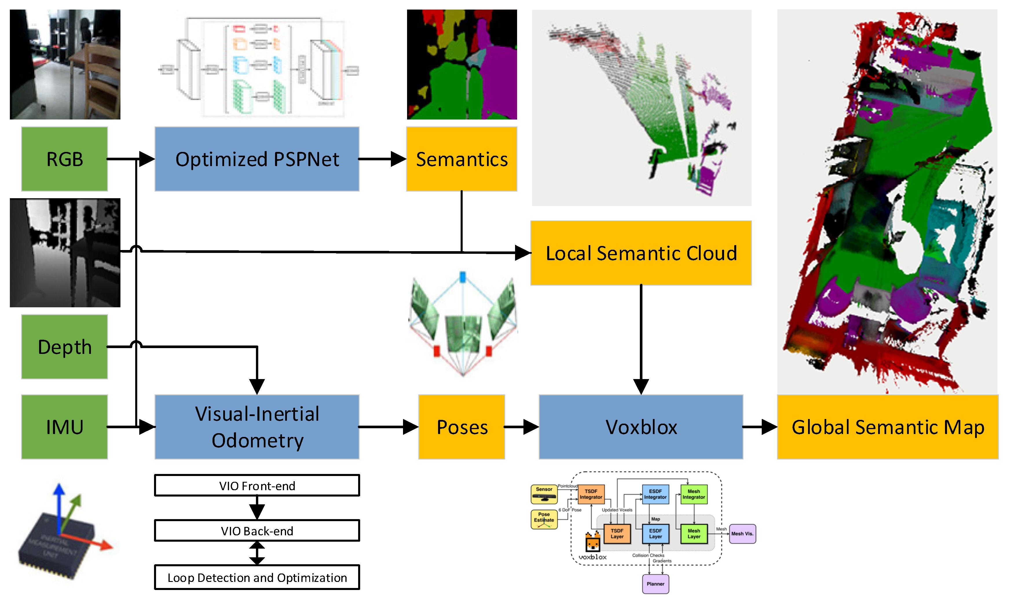
To achieve real-time reconstruction of globally consistent dense semantic maps on the CPU, CDSFusion is proposed. Our VIO introduced the depth information to obtain a precise scale, and FAST features were used to obtain fast feature tracking. We also provided a lightweight dense semantic fusion method, which fused the semantic point clouds using Voxblox. We optimized a PSPNet pre-trained model to provide the semantic information on a CPU in real time. An overview of the method in block form is shown in
Figure 1.
The proposed CDSFusion takes RGB frames, depth frames, and high-rate IMU measurements as input, and is composed of three modules, as shown in the
Figure 1. The input measurements are processed in an RGBD-based VIO module to estimate poses; a highly accurate and globally consistent trajectory estimation is given in this part. Semantic segmentation results of input RGB frames are gained in real-time using the lightweight semantic segmentation module. In our 3D reconstruction module, the local semantic cloud is generated using a semantic image and depth image, and also used to generate global 3D semantic map combined with the corresponding camera pose from VIO. The detailed description of the three modules is given in the following sections.
3.2. Visual-Inertial Odometry
The proposed VIO module is based on VINS-Mono. In our implementation, FAST features were adapted to speed up the VIO instead of Shi-Tomas corner features, and depth information was introduced to obtain a precise scale. The design choice for FAST features is not only driven by functionalities, but also experimental results which show that the FAST features are much faster than Shi-Tomas and ORB with the same or more robustness and accuracy. A series of experiments was designed to investigate the good performance of the proposed VIO. The proposed VIO module includes three parts: a visual-inertial front-end which is in charge of processing the raw sensor data; a back-end used for fusing the processed measurements to obtain pose estimation; and a loop detection and optimization module used to re-localize and optimize poses according to the detected loops.
The front-end includes an IMU front-end and a vision front-end. The IMU front-end pre-integrates raw IMU measurements between two consecutive frames. The vision front-end detects FAST corners and tracks them between consecutive frames using the KLT sparse optical flow algorithm [
57]. For each new image, old features are tracked, and new FAST corner features are detected to maintain numbers of features in each image. Keyframes are also selected in the vision front-end. The depth information was led into the initialization procedure of the proposed VIO to initialize the VIO with a precise scale using PnP algorithms [
58].
At each keyframe, pre-integrated IMU, visual, and loop measurements are added to a sliding window which constitutes the VIO back-end. If there are no loops detected, the back-end consists of a sliding window including pre-integrated IMU and visual measurements. We perform nonlinear optimization for the sliding window and solve the problem using the Ceres solver [
59].
The loop detection and optimization module relies on the DBoW2 library, a state-of-the-art bag-of-words place recognition approach. For each keyframe, FAST features are detected and described by the BRIEF descriptor [
60]. The descriptors are treated as the visual word to obtain the visual database which needed by DBoW2. Then we can acquire loop-closure results by using DBoW2. The loop-closure results are delivered to VIO back-end to constitute a sliding window with other measurements. In addition, there are re-localization and global pose graph optimization procedures after loop detection. The re-localization and pose graph optimization procedures are similar to VINS-Mono, and the proposed VIO leads into the depth information to obtain more precise results.
3.3. Semantic Segmentation
The semantic segmentation approach of our system is based on the PSPNet, which proposes a pyramid pooling module to extract multi-scale information. Global context information can be extracted using PSPNet, and more accurate and reliable results for semantic segmentation or scene parsing can be obtained by using both local and global information. The design enables PSPNet to take as much image information as possible into account and gain better appearance.
The original implementation of PSPNet is with Pytorch. We optimized the pre-trained model using Model Optimizer of Intel OpenVINO, and model prediction was re-implemented with Inference Engine, which utilizes SIMD operations on CPUs. We transformed the pre-trained model to Open Neural Network Exchange (ONNX) format, because Pytorch is not yet supported by the Model Optimizer directly, and transformed the ONNX model to the final model using the Model Optimizer.
The semantic segmentation module processes each RGB frame and returns some probability vectors for each pixel of the RGB frame. The value of probability vectors represents the probability that the pixel belongs to the corresponding class. We simply classify the pixels as the class corresponding to the maximum value in each probability vector and color them with a predefined category color. The final semantic image is composed of the colored pixels and delivered to the 3D reconstruction module.
3.4. 3D Reconstruction
We reconstructed a 3D semantic map of the scene based on Voxblox, which mainly includes two steps: building an accurate global 3D map and semantically annotating the map. For building an accurate global 3D map, a voxel-based (TSDF) model is used to filter out noise and extract the global mesh. At each keyframe, the current depth image is transformed to a 3D point cloud. Then Voxblox and the “fast” option discussed in [
17] are adapted, the local 3D point cloud is transformed to a local mesh, and then the local mesh is integrated into the global mesh. The resolution of the global mesh can be assigned by people. Most importantly, all of the procedures are processed in real-time on a CPU.
For semantic annotation, the 3D reconstruction module uses 2D semantically labeled images corresponding to each keyframe to semantically annotate the global map. The 2D semantic labels are from the semantic segmentation module. To this end, when generating local 3D point cloud, we also propagate the semantic images. Using the 2D semantic images, we can easily attach the semantic label to each 3D point produced by the depth image and acquire local 3D semantic point cloud. Then, we can use Voxblox to obtain a local semantic mesh. Combined with the pose of the current frame from the VIO module, local maps can be fused into the global map and the global semantic mesh of the environment can be obtained.
Combined with the above three modules, CDSFusion can achieve dense semantic SLAM in real-time and generate a complete semantic map. Notably, the system runs only on a CPU. A series of experimental results are designed in
Section 4 to investigate the dense semantic mapping ability of the proposed CDSFusion.
4. Experiments
In this section, the experimental results of the feature points’ comparison, the VIO module, and the full dense semantic SLAM system are shown. In the experiments of feature points’ comparison, we replace the Shi-Tomasi features used in VINS-Mono with ORB and FAST features, and compare the three different features in accuracy and speed. To confirm the speed, we evaluate the time of VIO front-end per frame for VINS-Mono, ORB-VINS-Mono, and FAST-VINS-Mono, mainly including feature extraction and optical flow tracking. ORB-VINS-Mono indicates that the Shi-Tomasi features in VINS-Mono are replaced with ORB features, and FAST-VINS-Mono means that the Shi-Tomasi features are replaced with FAST features. For accuracy, we evaluate the trajectories of the three methods using the method proposed by Zhang et al. [
61]. In the experiments, only the translation Root Mean Square Error (RMSE) is used for the accuracy evaluation, because the ground truth of the quaternion in the test datasets is wrong. The translation RMSE is defined as
is the error between the aligned position estimation and the position groundtruth .
In the experiments of VIO, we compare the proposed VIO algorithms with VINS-RGBD and VINS-Mono in accuracy and speed. For accuracy, we evaluate the trajectories of VINS-Mono, VINS-RGBD, and CDSFusion using the method proposed in [
61]. The RMSE is used for accuracy evaluation. To confirm the speed, we evaluate the time of VIO front-end per frame for the proposed VIO and VINS-RGBD, mainly including feature extraction and optical flow tracking.
We further validate the effectiveness of the full system on two scenes. In the experiments of the full system, the semantic map of groundtruth, textured map of groundtruth, generated map using Kimera, and a generated map using the compared method on a GPU are shown for comparison. In the experiments, our system runs only on a CPU. Completeness of the semantic map is used for evaluation. All experiments are done on a Huawei matebook13 equipped with i7-8565U CPU @ 1.80 GHz, 8 GB memory, and a NVIDIA GeForce MX250. To increase the credibility of the experiments, any acceleration to the proposed method is not added, the input experimental data are consistent, the mapping resolution is 0.02 m, and all other parameters are kept constant using system default values unless stated otherwise.
4.1. Feature Points Comparison
The experiments of this section are all presented with the public handheld and wheeled robot datasets provided by VINS-RGBD. The datasets are taken with the original Intel RealSense D435i camera, and the ground truth poses in the datasets are provided by OptiTrack [
62] tracking system. The results of RMSE are shown in the
Table 1. The RMSE results of VINS-Mono have been shown in VINS-RGBD, and the results are quoted directly.
The results show that VINS-Mono and FAST-VINS-Mono achieve higher accuracies than ORB-VINS-Mono. Especially for the Handheld Simple, the Wheeled Slow, and the Wheeled Normal datasets, the accuracy of ORB-VINS-Mono is much lower than VINS-Mono. In the Handheld Simple and the Wheeled Normal datasets, the reason is that ORB-VINS-Mono often calculates a wrong scale far from the true scale. In the Wheeled Slow datasets, the lower accuracy is because of tracking drift. However, in the Handheld Normal, the Handheld With more Rotation and the Wheeled Fast datasets, ORB-VINS-Mono obtains comparative accuracy with VINS-Mono, because of more accurate scale and no tracking drift. Compared with VINS-Mono, FAST-VINS-Mono achieves the similar accuracy on the whole. In the Handheld Simple, the Handheld Normal, and the Wheeled Normal datasets, the two methods obtain similar accuracy. For the Wheeled Slow dataset, however, VINS-Mono obtains a more accurate result because Shi-Tomasi features are more stable and accurate for tracking than FAST features when camera moves slowly. For the Wheeled Fast and the Handheld With more Rotation datasets, FAST-VINS-Mono achieves better performance. Especially for the Wheeled Fast dataset, FAST-VINS-Mono obtains nearly two times greater accuracy than the original VINS-Mono. The reason is that FAST-VINS-Mono adapts FAST features for tracking. Benefiting from that, the VIO is faster, can track more frames, and gain richer geometric structure information, which makes the VIO more accurate for fast motion or more rotation. We are also interested in the robustness and the success rate is used for evaluation. For each dataset, the three methods are run ten times, and success times are counted to calculate the success rate. The results of success rate are shown in
Table 2.
The results show that FAST-VINS-Mono obtains the same success rate with the original VINS-Mono, and ORB-VINS-Mono fails to track most times. Especially for the Wheeled Slow dataset, ORB-VINS-Mono only succeeds four times out of ten; however, FAST-VINS-Mono and VINS-Mono both success nine times out of ten, showing their robustness. The reason might be that ORB features are suitable for feature matching but unsuitable for optical flow tracking. We also compare the efficiency of the three methods. The mean time consumption of front-end per frame is counted in our experiments. The results are shown in
Table 3.
The results show that the time of the whole VIO front-end per frame in FAST-VINS-Mono is nearly three times faster than the original VINS-Mono. The front-end of VINS-Mono extracts Shi-Tomasi corner features and performs optical flow tracking. However, FAST-VINS-Mono extracts FAST features and can be used for faster pose estimation. The results also show that compared with the original VINS-Mono, ORB-VINS-Mono only speeds up a little. According to the above experiment results, we can draw the conclusion that FAST-VINS-Mono is faster than the original VINS-Mono with similar accuracy and robustness, and the two methods achieve better performance than ORB-VINS-Mono.
4.2. Visual-Inertial Odometry
The experiments of this section are also presented with the public handheld and wheeled robot datasets provided by VINS-RGBD. The results of RMSE are showed in the
Table 4. VINS-RGBD has been compared with VINS-Mono in their paper, and we quoted the comparison results directly.
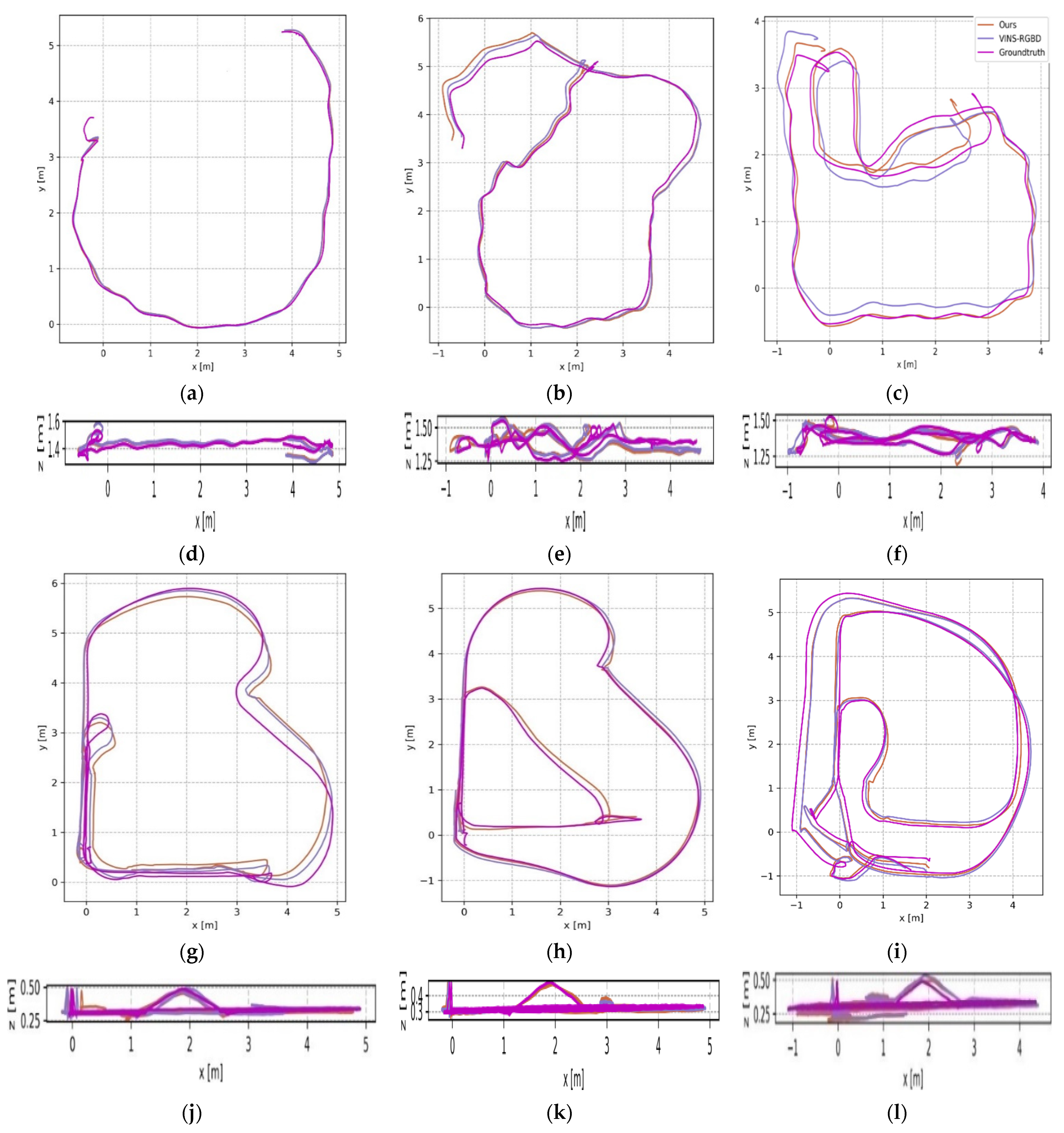
The results show that the accuracy of our VIO module and VINS-RGBD are better than VINS-Mono. CDSFusion obtains the highest accuracy in four datasets, and VINS-RGBD gets the highest accuracy for two datasets. Compared with VINS-RGBD and VINS-Mono, our VIO module can achieve similar and even higher accuracy. Compared with VINS-Mono, ours is more accurate for all test datasets, which is mainly because our method leads into precise scale from depth information. Especially for the Handheld Simple dataset, our method achieves maximum accuracy improvement which is nearly four times greater. Compared with VINS-RGBD, ours achieves similar accuracy on the whole, because both methods lead into precise scale. For the Wheeled Slow dataset however, VINS-RGBD obtains a more accurate result, because Shi-Tomasi features are more stable and accurate for tracking than FAST features when camera moves slow. For the Wheeled Fast and the Handheld With more Rotation datasets, our method achieves better performance. This is because our method adapts FAST features for tracking. Benefiting from that, our VIO front-end is faster, so our method can track more frames and gain richer geometric structure information, which makes the VIO more accurate for fast motion or more rotation. To intuitively demonstrate the accuracy comparison of the different methods in
Table 1, the trajectories of those datasets are shown in
Figure 2. VINS-RGBD has proved their method can achieve higher accuracy than VINS-Mono, so we simply compared our method and VINS-RGBD in the figure.
The results show that our method achieves the expected results.
Figure 2 shows that our method achieved a similar accuracy to the VINS-RGBD in all test datasets. The trajectories of our method and VINS-RGBD are close to the ground truth with a maximum drift error of no more than 0.50 m. The maximum drift error of our method is 0.49 m in the Wheeled Slow dataset because of long-term cumulative error before loop closure. The maximum drift error of VINS-RGBD is 0.50 m with the Handheld With more Rotation dataset, while our method reduces the error to 0.41 m by tracking more frames and gaining more information. The minimum drift error is nearly 0.01 m with the Handheld Simple and the Wheeled Fast datasets. For the Handheld Simple dataset, the reason is that the dataset is without large rotation and high speed. For the Wheeled Fast dataset, our method can track lots of frames and gain rich information, so it can achieve the minimum drift error for fast motion.
We further compared the efficiency between different methods. The mean time consumption of front-end per frame was counted in our experiments. The time consumption is shown in
Table 5. Only our method and VINS-RGBD were compared, because the two methods can achieve similar accuracy, which is higher than VINS-Mono.
The results show that the time of the whole VIO front-end per frame in our method is more than two times faster than VINS-RGBD. The front-end of VINS-RGBD is similar to VINS-Mono which extracts Shi-Tomasi corner features and performs optical flow tracking. Compared with them, our method includes a lightweight VIO and can be used for faster pose estimation. According to the above experiment results, we can draw a conclusion that our method is faster than VINS-RGBD and VINS-Mono with the same or even higher accuracy.
4.3. Dense Semantic SLAM
We evaluated our method in two scenes: a modified room dataset provided by the open source project semantic_slam [
63], whose original dataset is without the ground truth of the semantic map, and this includes depth images, RGB images, and camera poses; and an office dataset recorded by us using an UAV equipped with an Intel RealSense D435i camera and a NVIDIA TX2 onboard computer, which includes depth images, RGB images, and IMU measurements. The groundtruth 3D maps of the two datasets, including semantic maps and textured maps, were given by BundleFusion and the semantic segmentation results were obtained using a PSPNet pre-trained model trained with SUNRGBD [
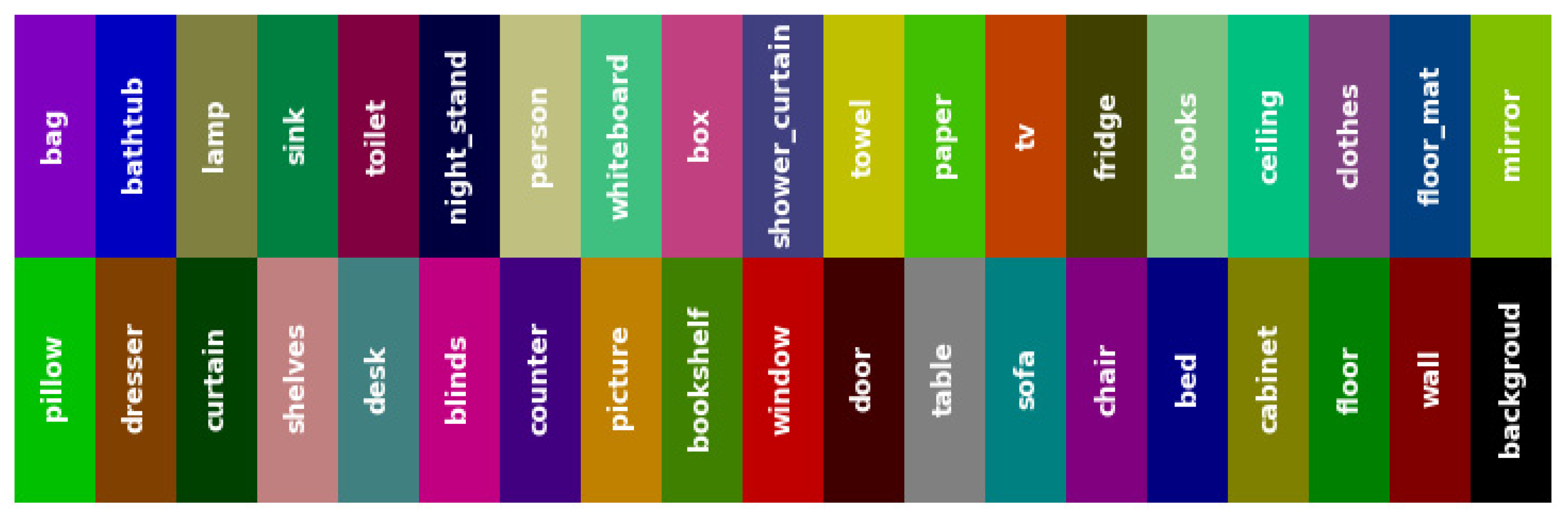
64]. We demonstrate the results of 3D semantic reconstruction using our method and others. After extensive experiments we found that it is difficult for other methods to reconstruct a complete 3D semantic map of the environment on a hardware platform with limited computational resources, and this is also true for indoor areas that are not very large. For comparison, we show the 3D semantic maps of the complete scene generated by a method using GPU acceleration and the semantic maps generated by Kimera. The method used for comparison adapts the same PSPNet pre-trained model but without optimization of model pruning and the remaining parts of the method are the same as CDSFusion. For convenience, we call the method as GDSSLAM (GPU-Based Dense Semantic SLAM) in the following experiments. The name CDSSLAM (CPU-Based Dense Semantic SLAM) is also introduced to represent GDSSLAM without GPU acceleration. The legend of semantic information is shown in
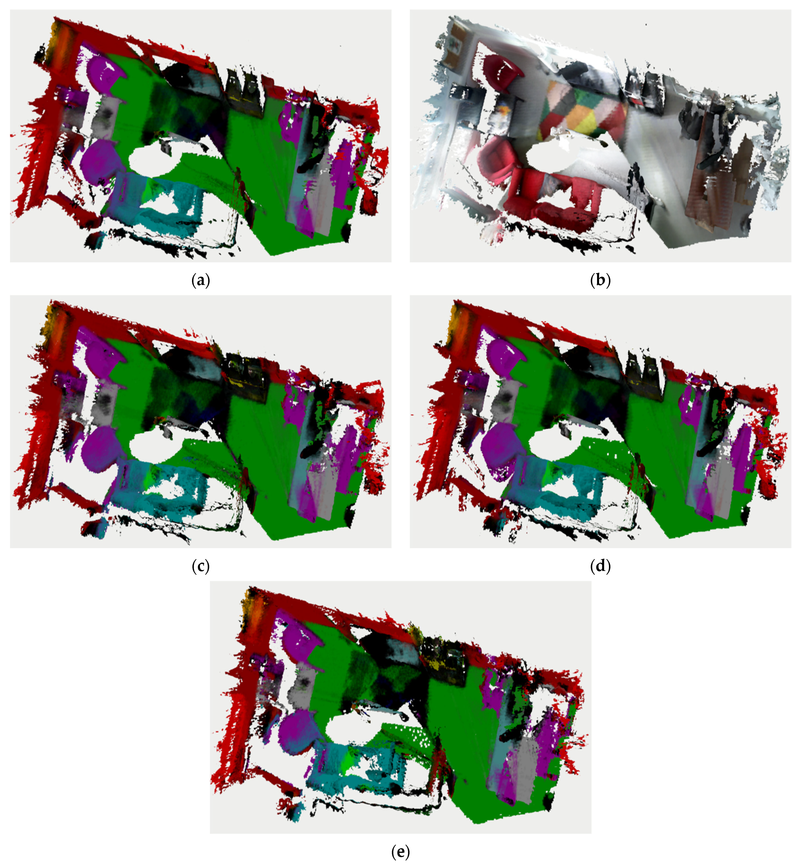
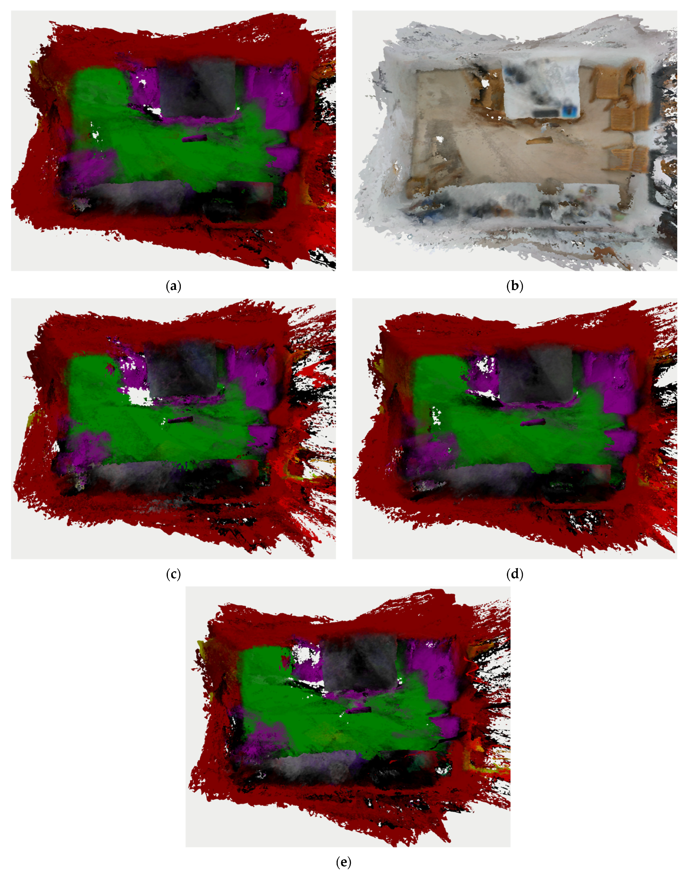
Figure 3, which shows the correspondence between color and category in semantic maps. The reconstruction results of the room dataset are shown in
Figure 4.
The results show that the semantic reconstructed result of CDSFusion achieves the same completeness with the ground truth, as shown in
Figure 4a,e. Although there are some missing details compared with the ground truth, our method can correctly color according to semantic classes, such as chairs, floor, and sofa, and ours is close to ground truth, as shown in
Figure 4b,e. In addition, we reconstructed a 3D semantic map with the same completeness as the semantic reconstructed result of GDSSLAM which used GPU acceleration, which is certainly exciting for a dense semantic SLAM system running on a CPU only, as shown in
Figure 4c,e. Compared to the result of Kimera, the result of CDSFusion is closer to the ground truth in some details, such as the chair in the lower left, but Kimera achieves better performance on the whole because it runs semantic segmentation offline, as shown in
Figure 4d,e. We also showed the reconstruction results of the office dataset, which was obtained using a UAV while flying in an office, shown in
Figure 5.
The results show that our method can robustly and accurately track camera poses even under fast UAV motion, resulting in a globally consistent 3D map without significant area overlap, as shown in
Figure 5e. Although the results of our method have less smoothness, and some details are missed compared with the ground truth, our method achieved the same completeness with ground truth, as shown in
Figure 5a,e. Compared with the textured map of ground truth, our method can correctly color according to semantic classes, as shown in
Figure 5b,e. Compared with the GDSSLAM needing GPU acceleration, although some details are missed, such as the top right-hand corner and bottom right-hand corner, a correct semantic map is given by our method in real-time on a CPU, as shown in
Figure 5c,e. Compared to the result of Kimera, our method achieves better performance in some details, such as the floor, and obtains the same completeness, even though Kimera runs semantic segmentation offline, as shown in
Figure 5d,e. Because of the influence of the sundries in the dataset, some noise appears on the right side of the map. We are also interested in the efficiency of the system, also including the CDSSLAM that cannot reconstruct a complete map on a CPU. Therefore, we designed experiments to investigate the time consumption per frame in generating semantic maps between different methods. The mean time consumption per frame was counted in our experiments for the three methods when processing two datasets, as shown in
Table 6.
Table 6 demonstrates that the CDSSLAM consumes a lot of time in generating 3D semantic maps. This causes the 3D reconstruction thread to be squeezed, which limits the generation of complete 3D semantic maps. However, the GDSSLAM greatly improves the image processing efficiency with the acceleration of a dedicated graphics processor, thus enabling real-time semantic segmentation and 3D map reconstruction. When computing resources are limited, dedicated graphics processors are often not available. In contrast to CDSSLAM, the proposed CDSFusion increased the processing speed per frame in the test datasets by more than three times only relying on a CPU, and the speed even close to that of the GDSSLAM in the office dataset. Since the office dataset we recorded is without the pose information, the pose estimation of frames makes the time consumption per frame of the office dataset slightly higher than that of the public room dataset which provides the poses. In order to verify the effectiveness of our model optimization, we also designed experiments to investigate the time consumption per frame in semantic segmentation between different methods. The mean time consumption per frame was counted in our experiments for the three methods when processing the two datasets, as shown in
Table 7.
The results show that the CDSSLAM consumes a lot of time in semantic segmentation, which is the main reason for the slow semantic map generation. The GDSSLAM greatly improves the segmentation speed with the acceleration of a dedicated graphics processor, thus enabling real-time semantic segmentation and map generation. In contrast to CDSSLAM, the proposed CDSFusion increased the segmentation speed per frame in the test datasets by more than three times, only relying on a CPU, and the speed is even close to that of the GDSSLAM in the office dataset.
5. Conclusions
In this paper, a dense semantic SLAM system for indoor environments using CPU computing was proposed, named CDSFusion. The operation efficiency of the proposed method on a CPU was improved while ensuring localization and reconstruction accuracy. CDSFusion is the first system which can process visual-inertial SLAM, semantic segmentation, and dense 3D reconstruction simultaneously in real time on a CPU. The system includes three key components: a fast and accurate VIO module, a lightweight real-time semantic segmentation module, and a lightweight 3D mesh reconstruction module. CDSFusion is modular and allows replacing each module or executing each module in isolation, so the system can be improved by making a module perform better. We hope CDSFusion can provide a solid basis for future research on robot perception, especially for lightweight dense semantic SLAM.
Although CDSFusion achieves dense semantic SLAM on a CPU, we still see some directions for future research. Our VIO module is sensitive to fast camera motion, and we are interested in improving the robustness and accuracy of the VIO in fast camera motion. Another research direction concerns the accuracy of the dense semantic map. Our research only considers the completeness, but the accuracy is also important. Higher accuracy requires more accurate and lightweight semantic segmentation network and real-time reconstruction. We will try to optimize some other network such as MobileNetV3 [
65] and speed up the mesh reconstruction. Additionally, we will try to improve CDSFusion and adapt the system on-board an UAV in the future. The system has been tested on NVIDIA TX2 and obtains good results with a room dataset at present.


