Abstract
Our research concerned the development of an autonomous robotic navigation system for orchard harvesting with a dual master-slave mode, the autonomous navigation tractor orchard transport robot being the master followed by a navigation orchard picking robot as the slave. This addresses the problem that in single master-slave navigation mode, agricultural combined harvesting equipment cannot stop repeatedly between rows of apple trees and drive continuously when turning. According to distances obtained from a global positioning system (GNSS), ground points were used to switch the navigation mode of the transport and picking robot. A cloth simulation filter (CSF) and random sample consensus (RANSAC) algorithm was used to obtain inter-row waypoints. The GNSS point was manually selected as the turn waypoint of the master and a kinematic model was used to compute the turn waypoints of the slave. Finally, we used a pure pursuit algorithm to track these waypoints sequentially to achieve master-slave navigation and ground head master-slave command navigation. The experimental results show that the data packet loss rate was less than 1.2% when the robot communicated in the orchard row within 50 m which meets the robot orchard communication requirements. The master-slave robot can achieve repeated stops in the row using follow navigation, which meets the demands of joint orchard harvesting. The maximum, minimum, mean and standard deviation of position deviation of the master robot were 5.3 cm, 0.8 cm, 2.4 cm, and 0.9 cm, respectively. The position deviations of the slave robot were larger than those of the master robot, with maximum, minimum, mean and standard deviation of 39.7 cm, 1.1 cm, 4.1 cm, and 5.6 cm, respectively. The maximum, minimum, mean and standard deviation of the following error between the master-slave robot were 4.4 cm, 0 cm, 1.3 cm, and 1 cm respectively. Concerning the ground head turn, the command navigation method allowed continuous turning, but the lateral deviation between robots was more than 0.3 m and less than 1 m, and the heading deviation was more than 10° and less than 90°.
1. Introduction
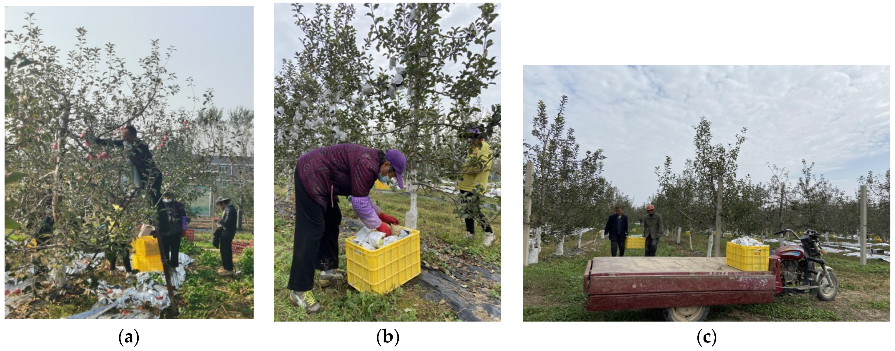
With the extreme labor shortage in the seasonal agricultural industry, the commercial harvesting of fresh fruits, such as apples, is highly dependent on human labor, resulting in labor costs accounting for 60% of variable production costs [1,2,3] as shown in Figure 1, where the harvesting process consists mainly of picking and transportation. To alleviate labor constraints, some research groups and companies have developed single-arm [4,5] or multi-arm picking robots [6,7], or used human-machine collaboration [8,9] to replace manual operations at individual stages of picking or transportation. However, some scholars have proposed the use of combined harvesting robots to collaboratively complete picking and transportation, and their simulation results have shown that the co–robotics not only greatly reduced the labor intensity, but also increased the picking efficiency by about 60% [10]. Therefore, combining picking robots and transport robots to complete picking is a trend in the development of fruit picking technology [3] and a hot spot for multi-robot research in agriculture [11].
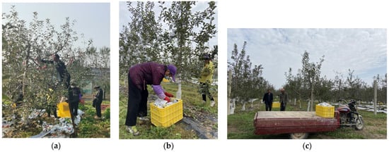
Figure 1.
Manual apple picking and handling. (a) Climbing ladders for apple picking; (b) picking and placing in fruit boxes; (c) placing apple boxes on the transport truck.
1.1. Objective of the Study
The objective of this research was to develop a master-slave combined harvesting robot navigation system that operates in the same row, while considering fruit tree height and branch growth. In this navigation system, the combined harvesting robot can perform within-row cooperative harvesting and cross-row continuous turning. In-row cooperative harvesting means that the combined harvesting robots can repeatedly stop in a fixed formation within a fruit tree row, while the picking robots stop and carry out the picking operation according to the fruit tree planting array, put the picked fruits into the fruit baskets of the transport robots, and then move on to the next tree when the harvesting is finished. Continuous turns across rows require the combined robot to continuously track the turn path to reduce the drive time when not operating. For this purpose, a combined harvesting robot navigation system was developed as a navigation method, with communication technology, navigation technology, and control technology, and the effectiveness of the navigation system was verified in orchard experiments [12].
1.2. Related Works
As early as 2004, Noguchi et al. [13] proposed the concept of master-slave navigation based on the combined harvesting method for hay in large fields. The master-slave navigation was divided into two modes: command navigation and follow navigation [13,14]. A review of the literature reveals that the earliest record of master-slave navigation robots in orchards was the orchard spraying robots proposed by Moorehead et al. [15] in 2012, which used a centralized controller as the master and operated spraying robots with commanded navigation in the planned operation area. Similarly, Gonzalez-de-Santos et al. [16], and Kim et al. [17] first used a UAV to acquire ground information and then used command navigation based on ground images to operate the ground robot along the planned operation path. Ju et al. [18] used two UAVs and a ground robot to monitor the environment in an orchard, with the ground robot traveling ahead as the master and the UAV following as the slave. The experimental results showed that the master-slave robot could maintain a stable formation under this navigation mode. These studies all used one navigation mode, either command navigation or follow navigation. In a single master-slave navigation mode, the robots can only achieve continuous path tracking or maintain a fixed formation, which is not very flexible.
In terms of communication technology, there is currently little research on the communication of multi-mobile robots in orchards. Mao et al. [19] proposed an ad hoc on-demand distance vector routing (AODV) protocol based on a prediction model of the reception strength of Wi-Fi signals in an orchard and built a set of small physical platforms for communication based on a leader-follow structure to verify the practicality of the routing protocol in a dynamic environment. However, this needs to be tested in a real orchard scenario. Fei [20] installed XBEE modules on multiple picking bags and sent the data to a centralized controller via a wireless network. However, picking bags with XBEE modules are usually fixed in place, and XBEE requires high data throughput and is unsuitable for large data volume communication.
In terms of master-slave robot cooperative navigation, the problem of autonomous navigation of the master robot needs to be addressed first. The current research on autonomous navigation of orchard robots mainly focuses on automatic travel between rows of fruit trees, especially the use of light detection and ranging (LIDAR) to extract tree rows or detect trees and labels, which is regarded as a reliable method of autonomous navigation. For example, Zhang et al. [21] set landmarks at the ends of rows of fruit trees and used a laser scanner to detect the landmark information and build a local map of the orchard to ensure the robot’s autonomy in the orchard. Bergerman, et al. [22] fused a 2-D laser scanner, wheel, and steering encoder sensor data, and used the laser scanner to detect the landmarks at both ends of the orchard rows to bring about the vehicle’s straight and cross-row turns in the orchard. Shalal, et al. [23] fused vision and LIDAR information for detecting and distinguishing non-trunked trees with 96.64% detection accuracy. Bell, et al. [24] used a 3-D laser scanner to detect the features of posts and tree trunks in a pergola structure orchard to determine the robot’s travel centerline. Lepej and Rakun [25] relied on a 2-D laser scanner to detect landmarks for real-time robot map building and localization in an apple orchard. Blok et al. [26] used a probabilistic particle filter (PF) algorithm combined with LIDAR detection to achieve autonomous robot navigation within fruit tree rows by detecting tree rows. Jones, et al. [27] used multilayer LIDAR to linearly track vehicle trajectories marked on an offline map of a kiwifruit orchard, and experimental results showed an accuracy of ±75 mm. Zhang et al. [28] used Euclidean clustering and three point collinearity to extract the central feature points of fruit tree trunks scanned by 2-D lasers and fitted these central feature points into straight lines as robot navigation reference paths. Liu et al. [29] used single-line LIDAR to obtain orchard environment information, fused posture sensor correction information, then used least squares to fit a single-row fruit tree line, and finally combined the SVM algorithm to predict the centerline between orchard rows as the robot navigation reference path. Liu et al. [30] used a random sampling consistency algorithm with least squares to fit the trunk information detected by 3-D LIDAR, and then complementary fusion of the information based on the principle of optimal parallelism of the left and right trees rows to find the centerline of the fruit tree rows as the autonomous navigation path of the robot.
In these studies, the autonomous navigation robot has always walked along a set operational path without pausing in between. To ensure successful robot picking, Bayar et al. [31] proposed a method of human intervention to stop the robot, that is, a human presses the pause button to stop the robot when it travels in front of the apple tree autonomously, and then presses the button to make the robot walk after the picking is finished. To further improve the degree of automation of the picking robot operation, some scholars adopted methods such as laying rails and attaching radio frequency identification (RFID) tags to enable robots to complete spot parking by identifying apple trees with tags [32,33,34]. However, this method usually requires a lot of preparation work in orchards in advance. Sun et al. [35] used LIDAR to scan the surrounding environment and build an environmental map, then artificially set multiple path points in the map for parking, as needed, to make the robot pick autonomously along the planned path. This this method takes a lot of time in constructing an orchard map and set the picking points manually.
In terms of autonomous navigation control of the slave robot, Ding et al. [36] developed an autonomous following vehicle heading control system for orchards based on infrared sensor detection of relative heading angle, and theoretical modeling and control of a following vehicle control system based on infrared sensors and encoder detection of relative heading declination angle and front-wheel declination angle, respectively. This controlled autonomous following of the following vehicle. Bi et al. [37] designed a following system for master-slave orchard operation vehicles based on binocular vision, in which the following vehicle obtained the 3-D information on a black-and-white checkerboard to obtain spacing, lateral offset, and heading declination angle of the leader vehicle, relative to the following vehicle, to effect autonomous real-time following of the leader vehicle. In both autonomous following control systems, the robots did not communicate with each other, and the leader was operated remotely by a human. To determine if the slave can work with a master that can operate autonomously needs further study. Li et al. [38] used a fuzzy control method for following robots based on wireless communication to ensure that the robots travel on the same path by controlling the vehicle turning angle, heading, and speed, with a mean error of 5.88 cm between the two robots.
Finally, in the research of master-slave robot cooperative control, Zhang et al. [39] combined a master-slave motion model and sliding mode variable control method; the average lateral error of the robot navigation system was less than 0.04 m. Bai et al. [40] combined feedback linearization and sliding mode control theory to design an asymptotically stable path tracking control law and a formation-keeping control law, according to which the average tracking error of the master robot was 5.81 cm and that of the slave robot was 5.93 cm. The average tracking error of the master robot was 5.81 cm and the average tracking error of the slave robot was 5.93 cm. Zhang et al. [41] constructed a parallel cooperative model and designed a longitudinal relative position controller based on the dynamics principle and the bit-velocity coupling control method, under which the relative position deviation of the robot was 7.78 cm. However, these are mainly used in a large-field operation environment. Combined harvesting robots in large fields usually work together across rows, i.e., the operating paths do not overlap.
2. Materials and Methods
2.1. Overall Design of the System
In response to the problems in the above studies, a master-slave mode orchard combined harvesting robot navigation system was developed after reviewing the literature [42,43] and drawing on experiences of orchard robot navigation systems developed in other laboratories [44,45]. The system enables combine harvesting robots to achieve operational requirements by adopting different navigation modes during orchard harvesting. The navigation system of the orchard master-slave combined harvesting robot is composed of a picking robot with autonomous navigation as the master, and another transporting robot as the slave. When the master-slave robot works cooperatively in the row, the combined harvester robot team uses navigation mode to locate apple trees or vehicles by LIDAR detection and walks along the green dotted line. When the master-slave robot needs to make a turn at the head of the ground, the combined harvester team uses commanded navigation, relying on a global positioning system (GNSS) position information, to make the slave robot track the turning point and turn.
2.1.1. Structure and Design of the Master-Slave Navigation System
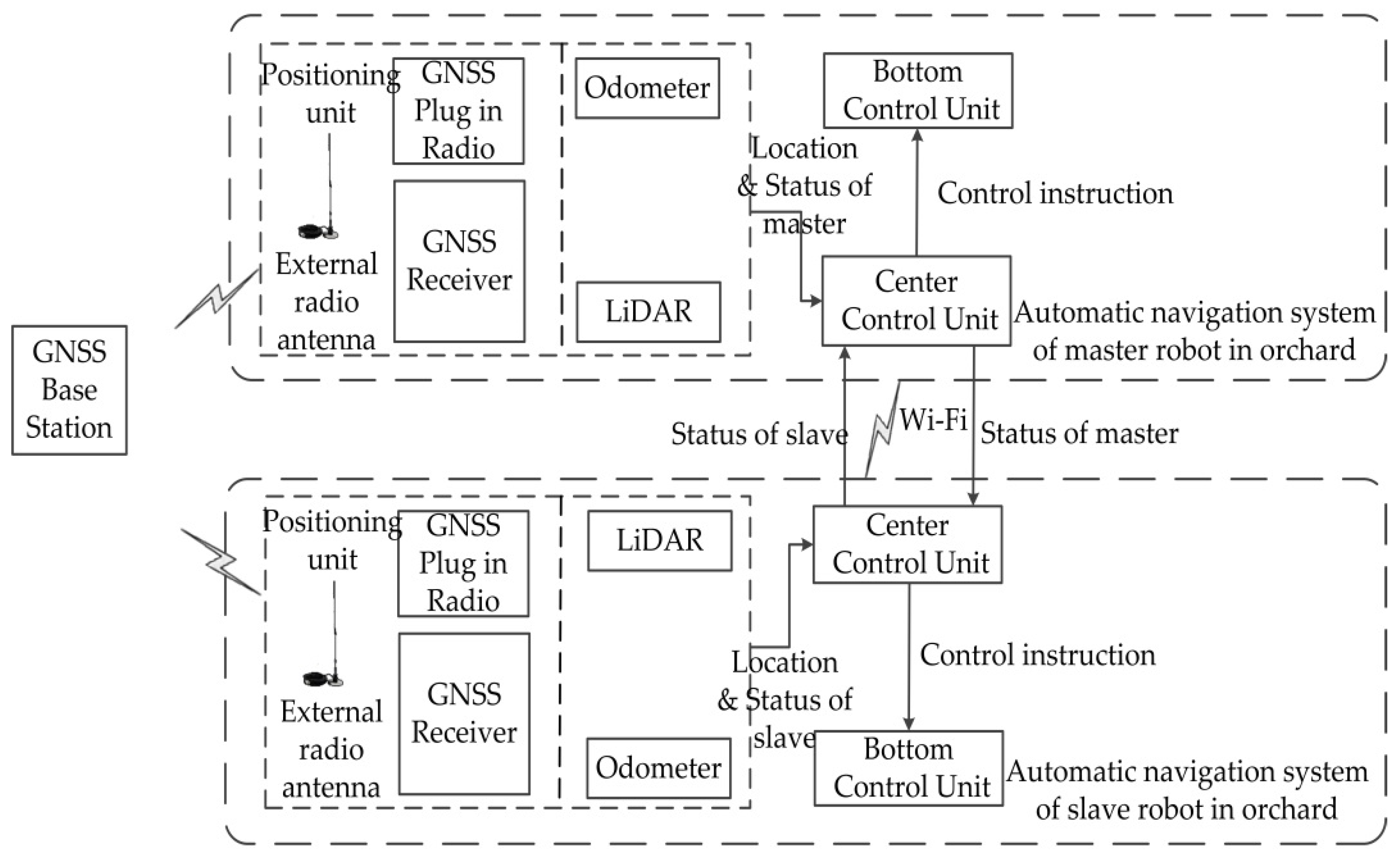
An overall framework of the orchard master-slave navigation system, including the automatic navigation system of the orchard master robot and slave robot, is depicted in Figure 2. The autonomous navigation system for the master-slave robot is the same basically, mainly including the positioning unit, the central control unit, and the bottom control unit. The positioning unit consists of an RTK-GNSS (includes GNSS plug in the radio, a GNSS receiver, external radio antennas, and GNSS base station), LIDAR, and odometer to provide positioning and operational status information to the central control unit of the robot. The central control unit streams its status data with the central control units of other robots via Wi-Fi, makes judgments based on the status information of other robots and the information provided by the positioning unit itself, selects the navigation mode applicable to the current working environment, and sends control commands to the underlying control unit.
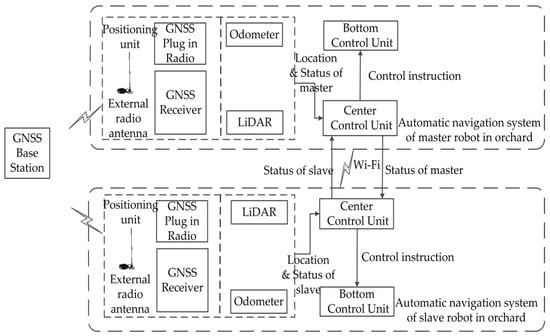
Figure 2.
Overall framework of the orchard master-slave navigation system.
2.1.2. Platform Construction of the Master-Slave Navigation in an Orchard
The hardware structure of the orchard master-slave robot cooperative navigation system is shown in Figure 3. The crawler robot that pulls the transport trailer is used as the master robot (the overall vehicle length after pulling the trailer is 2.05 m), and the crawler robot that performs picking work is used as the slave robot. The orchard master-slave robot cooperative navigation system consists of a positioning unit, a central control unit, a bottom control unit for the master robot, a positioning unit, a central control unit, and a bottom control unit for the slave robot.
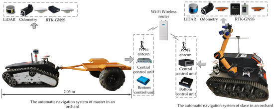
Figure 3.
Hardware structure of the orchard master-slave robot cooperative navigation system.
The central control unit of the master robot in a master-slave cooperative navigation system utilizes a UNO-2484G computer with a Core i7 CPU processor, 8 GB of memory, USB data transfer support, a wireless network card, and support for 802.11AC wireless protocol. The underlying control unit of the master robot includes a DBL6050-2E DC brushless motor controller and two 48 V brushless DC motors. The DC motors inside them carry incremental encoders. The mobile station in the positioning unit of the master robot has a Shanghai Sinan M600 and communicates with a Sinan T300 type base station at low frequency (461.050 MHz). This RTK-GNSS (M600) positioning accuracy is at the centimeter-level, with a horizontal accuracy of ±1 cm and a heading angle accuracy of 0.57°. The LIDAR in the positioning unit adopts Velodyne VLP-16 line LIDAR, which is set above the center point of the robots, where the horizontal scanning range of the LIDAR is 0–180°, the vertical scanning range ±15°, the measurement distance 0.4 m to 100 m, ad and the resolution 0.1°.
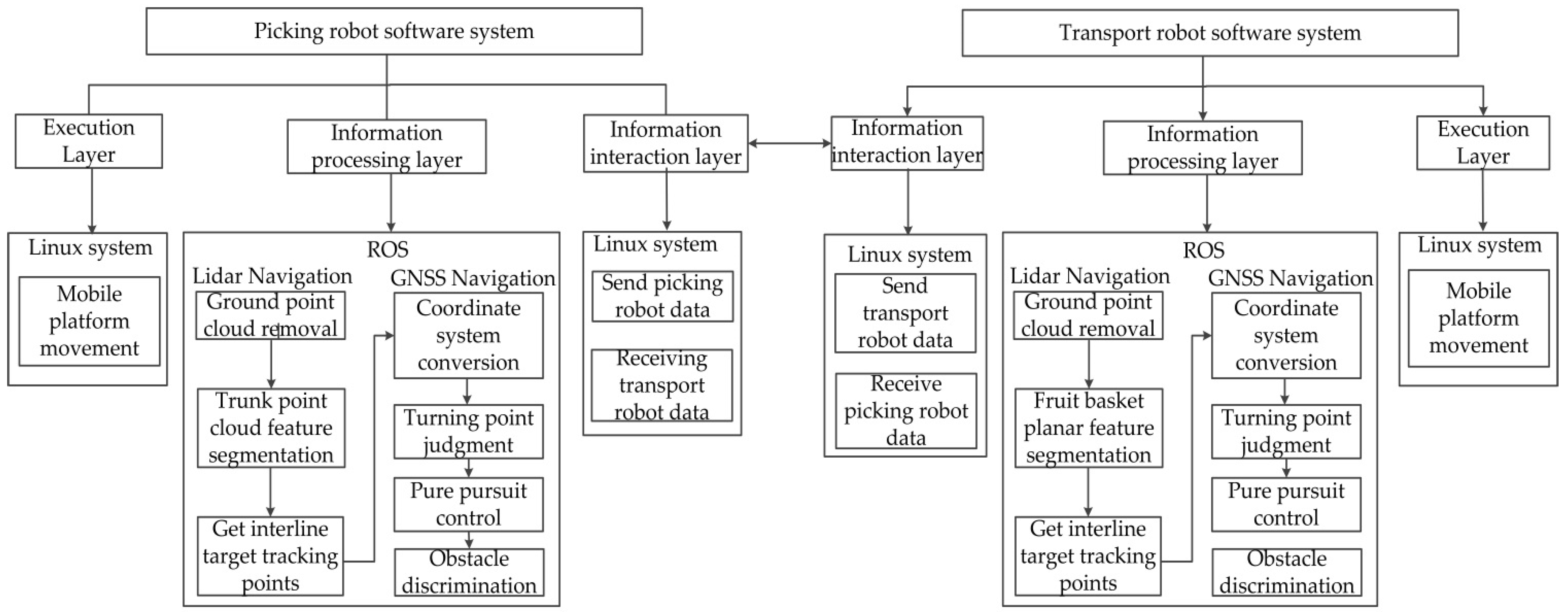
The system software of the combined orchard harvesting robot runs on a Linux system, and the system software of each robot is composed of three modules: an information interaction layer, an information processing layer, and an execution layer. The software system structure is shown in Figure 4. The information interaction layer is based on the Linux system model for data interaction between the picking robot and the transport robot. The information processing layer is based on the robot operating system (ROS) navigation program for the picking and transport robot group, and the execution layer is based on the Linux system mobile platform control. According to the speed information output from the information processing layer to the underlying servo controller, the autonomous walking of the picking and transporting robot is realized.
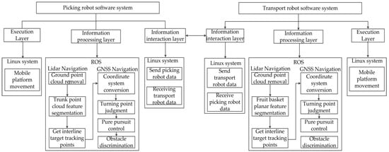
Figure 4.
Software system structure of the combined orchard harvesting robot.
2.2. Communication System for a Combined Orchard Harvesting Robot
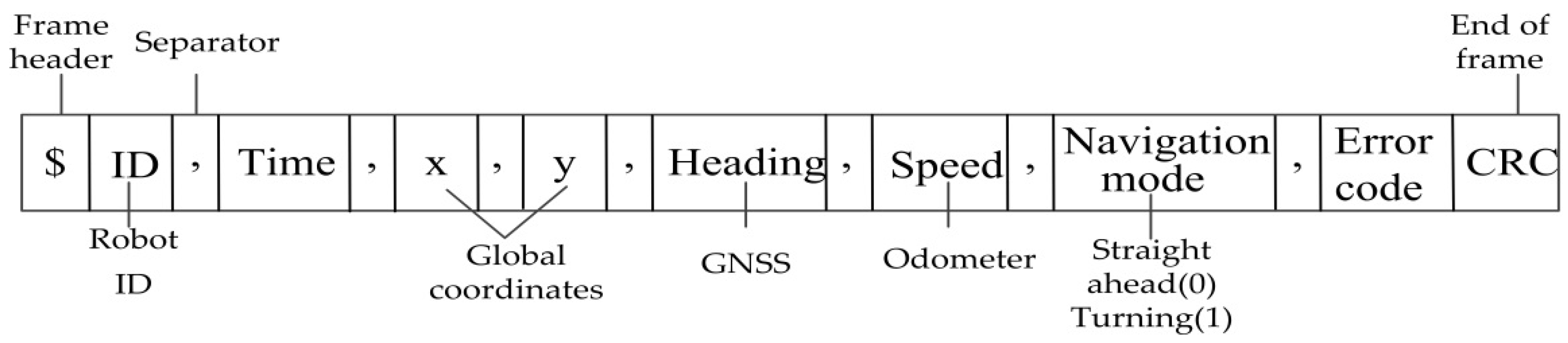
The picking and transporting robots in a combine orchard harvesting robot needs to navigate continuously during turns, and repeatedly stop between rows. The picking robot needs to ensure a minimum distance between it and the transporting robot in front of it without collision and be able to work with the transporting robot when stopped between rows. Therefore, the two robots need to communicate with each other and carry out cooperative picking and transportation based on exchanged information. In the above software system architecture for picking and transporting robots, the information interaction layer of the robots helps the master (transporting robot) and slave (picking robot) to transfer information, including GNSS coordinates, direction, speed, and navigation mode of the picking or transporting robot. The data frame format of the inter-robot communication protocol is shown in Figure 5.
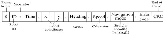
Figure 5.
Data frame format for inter-robot communication.
Where x and y are global coordinates, the robot heading and speed are obtained by the GNSS and odometer, respectively, and the navigation mode is divided into straight ahead (0) and turning (1). The data frame format of said communication protocol consists of a start character, an identifier, a data bit, a check bit, and a termination character. The data frame starts with the “$” symbol and ends with the cyclic redundancy check (CRC). The CRC is divided into the robot identity document (ID), the current time, the global coordinates X, Y, the heading, the navigation mode, and an error code indicated by “,”. The identifier of the data corresponds to the number of robots, i.e., the robot ID. The ID of the transport robot is 1 and the ID of the picking robot is 2.
2.3. Master-Slave Navigation Strategy
According to the actual operational requirements of orchard harvesting, the combined orchard harvesting robot needs to complete the action of stopping and going straight repeatedly, according to the tree planting pattern, when driving independently between rows. It does not need to stop when turning at the head of the ground to improve the operational efficiency. At the same time, the picking robots in this combined orchard harvesting robot needs to keep a minimum distance from the tractor-drawn transport robots driving in front of it to ensure that the arm of the picking robot can put the apples in the apple box and the two robots cannot collide. Therefore, the combined orchard harvesting robot uses different target feature approaches for inter-row and ground turns. GNSS is used to determine target feature points for ground turns and LIDAR is used to determine target feature points for in-row turns.
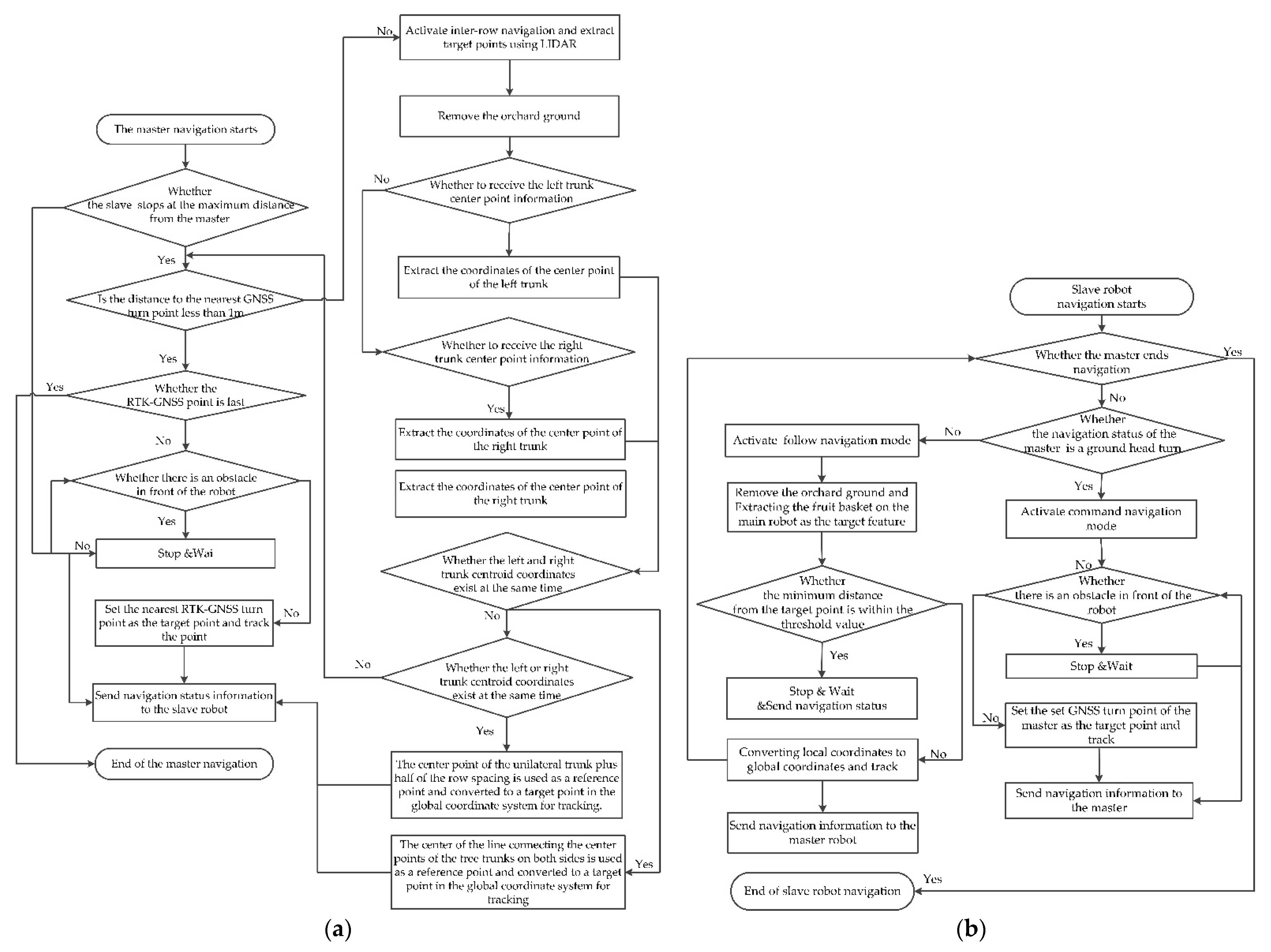
The above navigation strategy is carried out within the information processing layer in the software system of the master (transport) robot and slave (picking) robot, as shown in Figure 6. The master robot, after starting navigation, determines whether the current position of the robot is within the threshold range of the ground head-turning point if the slave robot does not stop navigation. When the robot is within the threshold range of the set GNSS turning point, GNSS navigation is used or, vice versa, LIDAR navigation is used. When GNSS navigation is used, it detects whether there is an obstacle in front of the robot, and when there is no obstacle, the nearest GNSS point is set as the target for tracking, and real-time navigation status information (speed, current position information, navigation mode) is sent to from the robot in real-time. When the GNSS coordinate point of the main robot is far from the ground turn, LIDAR is used for navigation, i.e., the apple tree trunk feature is used as the target feature for tracking. That is, the center point of the master robot is taken as the center point, and the apple tree trunks on the left and right sides of the tractor behind the master robot are extracted, respectively, and the middle point of the center point of the trunks on both sides is the robot’s tracking target. When the center point coordinates of only one side of the trunk exist, the detected trunk center point and half of the row distance are summed as the target tracking point. When no trunk is detected, GNSS navigation is performed and ends if the current GNSS point is the last.
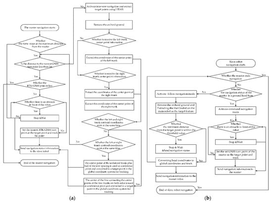
Figure 6.
Software structure of the orchard master-slave robot cooperative navigation system. (a) The master robot navigation strategy; (b) the slave robot navigation strategy.
After starting navigation, the slave robot sends and receives navigation status information (speed, current position information, navigation mode) from the master robot, and the slave robot ends navigation when the master robot ends navigation. Navigation during ground head turns is performed in the same way as the master robot. When LIDAR navigation is used in the apple tree rows, the apple basket on the master robot is used as the target feature for tracking, and the distance between the current robot and the apple basket is judged in real-time. When the distance is within the threshold value, it stops and sends out navigation status information while judging if the main robot ends the navigation. If not, the target tracking is continued, and the navigation status information is released.
To reduce the degree of ground interference in target feature extraction during LIDAR navigation, the orchard ground point cloud needs to be removed before extracting target tracking features. The installation position and scanning angle of the LIDAR have a large impact on the removal of orchard ground, so the 3-D LIDAR needs to be angularly and horizontally calibrated. Therefore, the LIDAR from the robot is first aligned with a white wall at close range, and the LIDAR scan range is considered normal when the LIDAR is rotated until the returned point cloud image became a straight line.
The robot is driven to the flat ground of the orchard and parked, and when the point cloud data sent by the receiving LIDAR is stabilized, at least three points are randomly selected within a frame of the obtained point cloud and calculated according to the plane equation to obtain the ground plane model Ax + By + Cz + D = 0. Then, other points are substituted into the plane model, the error is calculated, and the points whose difference (the set difference is 0.01) between the error and the k value in Equation (1) is less than the set threshold are the internal points, and the number of internal points under the model is counted. When the number of internal points in the model is greater than the maximum number of internal points already saved, the model parameters are updated until the set number of iterations is reached (the set number of iterations is 100 in this model).
Then, the ground is roughly extracted according to the plane model threshold using the Random Sample Consensus (RANSAC) algorithm to get the ground normal vector P. The rotation angle formed by this normal vector and the LIDAR coordinate normal vector Q is determined and, finally, the rotation matrix R is determined using the Rodriguez rotation formula.
where k is the plane threshold, τ is the probability of selecting an interior point during the iteration, %, η is the probability of selecting a point as an interior point in the point cloud, %, and n is the total number of point clouds.
where P is the plane normal vector, (A, B, C), Q is the normal vector of the LIDAR coordinate system, (0,0,1), ψ is the rotation angle of the vector P to the vector Q°.
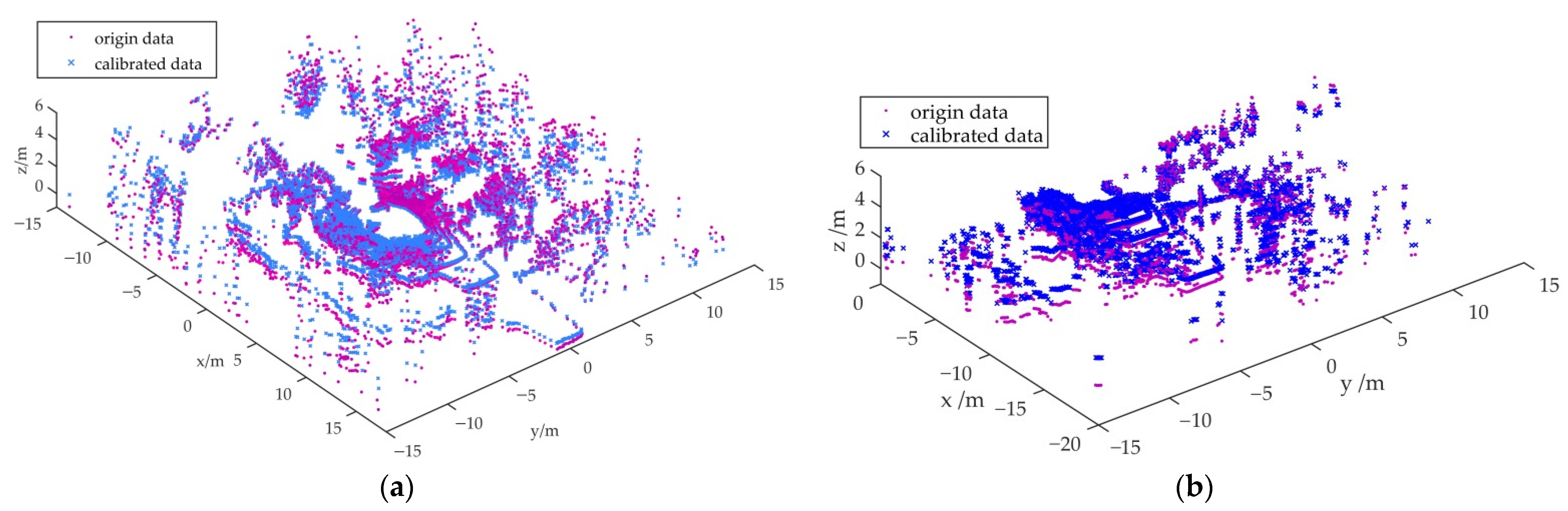
The point cloud data acquired from the LIDAR is angularly transformed by the rotation angle to obtain calibrated point cloud data. Due to the difference in the point cloud usage of the robots, the point cloud scan of the master robot is taken as [0,2π] and the point cloud scan of the slave robot is taken as [0,π]. The LIDAR point cloud calibration of the master robot in Figure 7a,b shows the LIDAR point cloud calibration for the slave robot.
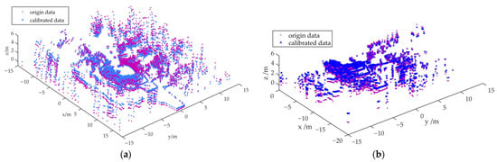
Figure 7.
Light detection and ranging (LIDAR) point cloud ground level calibration. (a) LIDAR point clouds of master robot calibration; (b) LIDAR point clouds of slave robot calibration.
2.3.1. Master Robot Navigation Phase
As the robot turns at the ground head, the GNSS sensor carried by the robot can be used to measure the ground head turn point as a targeted tracking point. This section of the article focuses on apple tree trunk feature extraction using LIDAR within apple tree rows for target tracking.
For LIDAR-based environment perception, the 3-D point cloud is usually divided into two separate subsets, ground points and non-ground points [46]; the apple tree trunk belongs to the non-ground point cloud. Therefore, it is necessary to remove the ground point cloud-first to improve the accuracy of obtaining apple tree trunk features.
In recent years, there have been a large number of studies on ground point cloud extraction and segmentation algorithms. For example, some scholars segmented ground point clouds based on the ground measurement model of LIDAR [47,48] or used RANSAC to fit the ground like a piece of a plane for segmentation [49,50,51], or distinguished ground and vegetation based on the threshold between ground point clouds [52]. These methods are simple and effective, but considering that the ground point cloud changes continuously above and below the horizontal plane when the robot is driving continuously in the orchard, the principle of a simulation filter (CSF) algorithm [53] is more indicative of the current terrain features than methods that rely on the height of a laser beam, a sensor or set thresholds.
The point cloud decreases as the distance between the object and the LIDAR increases. Point clouds that are far beyond their travel distance are usually not used when driving autonomously. Therefore, the unwanted point clouds are first removed by conditional filtering, and then the ground point clouds are segmented using the CSF in Equations (4)–(6).
where, in Equation (4), is the weight of the particle, is the position of the point in the point cloud in the “fabric” at time t, is the external driving element (such as gravity), is the internal link between the points in the point cloud. In Equation (5), Δt is the time step, g is the gravity constant 9.8 m/s2, is the new point in the point cloud at the next iteration. In Equation (6), is the displacement of the particle, is 1 when the particle is moving and 0 when it is not movable, is the adjacent particle of , and is the unit vector that normalizes the point to the vertical direction (0,0,1)T.
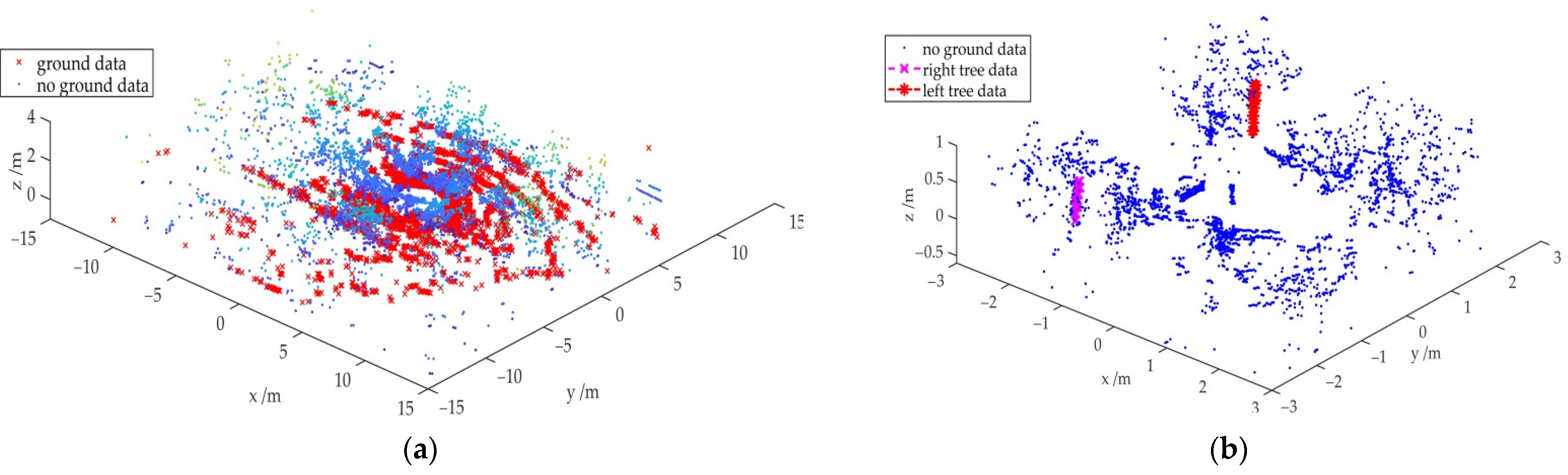
The point cloud is first divided into a grid (the size of a piece of the grid is 0.2 × 0.2 m), and the original point cloud and the grid-like point cloud are projected onto the same plane to find the nearest point of each point cloud and save the height information of the original point cloud. For the point cloud in a single grid, the displacement of the point cloud by gravity is then calculated by Equation (4), compared with the height of the point cloud before projection and iterated until the height change reaches a set threshold or iterated to a set value (set to 500). Finally, the displacement value is obtained from Equation (6), and when the displacement is less than the set value (set to 0.2 m), it is regarded as a ground point, or if greater, is regarded as a non-ground point. As shown in Figure 8a, in the calibrated LIDAR point cloud the above method is used to divide the point cloud into a non-ground point cloud and a ground point cloud, where the red points are ground, and the blue points are non-ground points clouds.
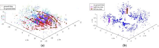
Figure 8.
The master robot extracts point cloud information of tree trunks on both sides. (a) Master robot segmentation of point clouds for ground and non-ground environments; (b) extraction of tree trunk feature point clouds.
On the segmented non-ground point cloud, using the robot as the origin, conditional filtering is used to extract the left apple tree row region and the right apple tree row region behind the robot, respectively, and then RANSAC is used to extract the cylindrical features of the tree trunk and segment them in this region. That is, randomly select any two-point coordinates, substitute into Equation (7), and derive the error of the points in the point cloud in the cylinder model, compare with the set threshold value, and through repeated iterations, when the error is less than the threshold value, the sample point belongs to the cylinder sample point, if the error is greater than the threshold value, it is the point outside the cylinder.
In Equation (7), is the radius of the cylindrical base circle, the distance from the point on the cylindrical surface to its axis is constantly equal to the radius, (x, y, z) is any point on the cylindrical surface, (x0, y0, z0) is a point on the cylinder axis, and (cl, cr, cn) is the cylindrical axis vector.
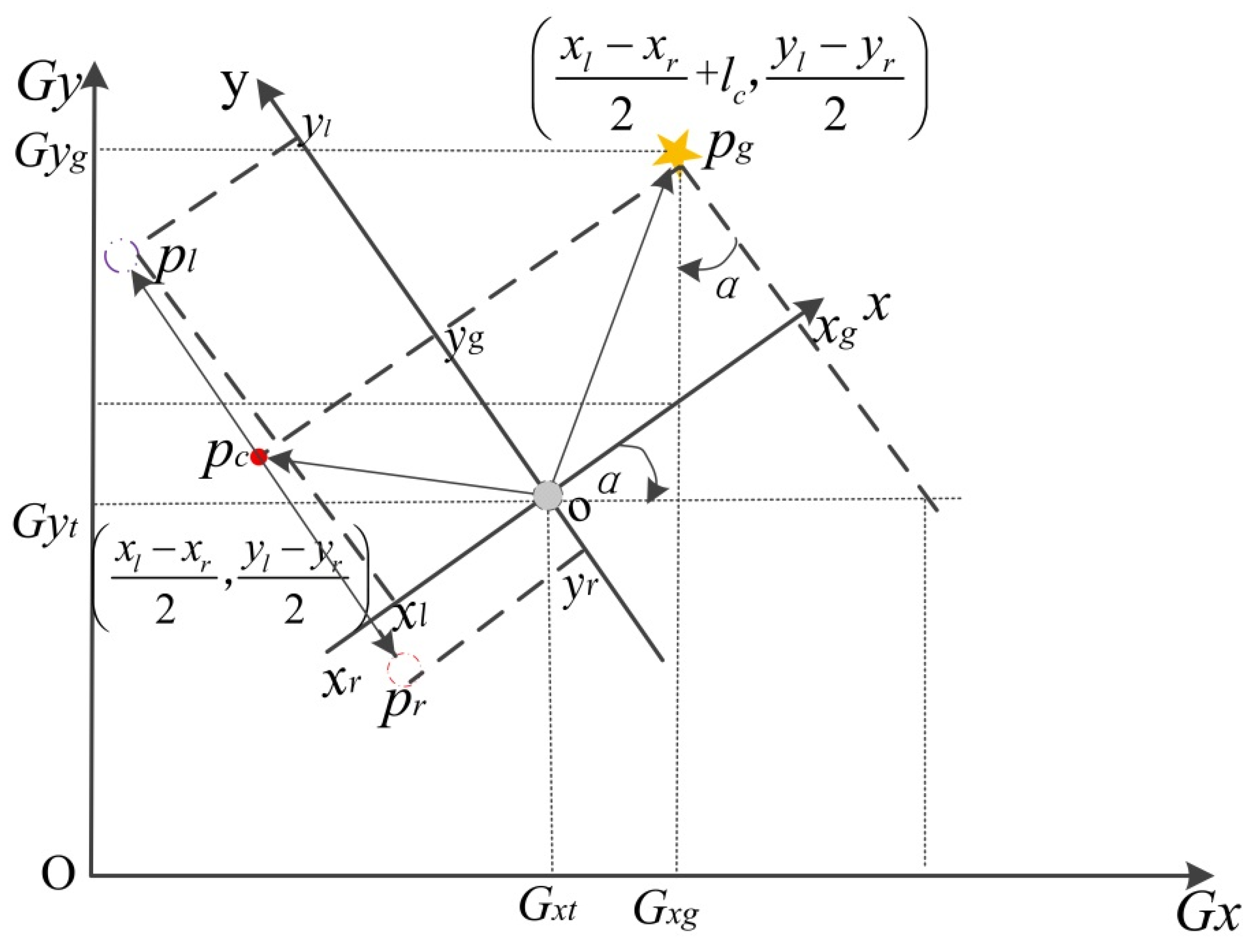
The left and right trunks on both sides of the master robot obtained by fitting the segmentation using the above algorithm are shown in Figure 8b. The obtained coordinates of the points pl and pr on the center of the left and right-side trunk axes in the xoy plane of the LIDAR coordinate system are (xl, yl) and (xr, yr), respectively. Then, the coordinates of the center pc of these two points are (), and the coordinates of the target point pg at a distance from this center are (), where is the entire length of the main robot after towing the trailer. Since the target point acquired by the LIDAR is relative, Equation (8) is used to obtain the coordinates of the point in the global coordinate system GxOGy. In Figure 9, the conversion between the LIDAR local coordinate system and the GNSS global coordinate system is shown.
In Equation (7), Gxg and Gyg are the horizontal and vertical coordinates of the target point pg in the global coordinate system, xg and yg are the horizontal and vertical coordinates of the target point pg in the local coordinate system of the LIDAR, Gxt and Gyt are the horizontal and vertical coordinates of the LIDAR in the global coordinate system, and α is the rotation angle between the LIDAR coordinate system xoy and the global coordinate system GxOGy.
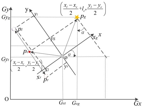
Figure 9.
Coordinate conversions of local coordinates in the global coordinate system.
2.3.2. Slave Robot Navigation Phase
In between the rows of apple trees, the slave robot uses the following navigation mode, after information exchange with the master robot, when the slave robot needs to extract and track the apple basket feature points on the master robot in front of it and use the feature points to track the master robot. As with the method of non-ground point cloud extraction by the master robot, the non-ground point cloud needs to be segmented from the calibrated point cloud using the Equations (1)–(6). The segmented result is shown in Figure 10a. A conditional filter is used in the non-ground point cloud to determine the following range of the slave robot. The area chosen here is the range where the robot radar is the origin, the front is less than or equal to 2 m, the left and right sides are less than ±0.5 times the row spacing, and the height is less than the canopy height.
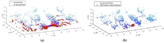
Figure 10.
Extraction of tractor point cloud features of the master robot. (a) Segmentation of point clouds from the slave robot for ground and non-ground environments; (b) extraction of feature points on the master robot tractor.
In the above following region, the Euclidean clustering method based on KD-Tree nearest neighbor search is used, where the Euclidean clustering formula is shown in Equation (9) and the ρ value is set to 0.1. Any point in the region is first brought in, and the k nearest points to this point are found. When the distance between these points is less than a set threshold, it is considered an object, and the clustering ends when the number of points clouds in the object no longer increases. Conversely, other points in the point cloud are brought in one by one until the number of point clouds in the object no longer increases.
In Equation (9), xi, yi, zi are the horizontal, vertical, and height coordinates of point i in the point cloud in the LIDAR coordinate system, and xoy, xj, yj, zj are the horizontal, vertical, and height coordinates of point j in the point cloud in the LIDAR coordinate system xoy.
In the above-obtained object point cloud, Equation (1) is used to fit the plane at RANSAC, as shown in Figure 10b. Finally, the center-of-mass extraction formula (10) is used to obtain the coordinates of the center-of-mass points of the fitted plane, using only the x, y coordinate values as feature points and converting them into coordinates in the global coordinate system using Equation (1) for following from the robot.
After the master robot walks to the orchard head turn point, the slave robot interacts with it and adopts the command navigation mode, at which time the slave robot acquires the GNSS head turn point of the master robot and tracks its turn point to complete the ground head turn.
2.4. Control System
The pure pursuit algorithm is a kinematic constraint-based algorithm that has been successfully applied in the trajectory tracking control of many robots [54]. The algorithm can determine the arc length to be traveled by the robot to the tracking path based on the set pre-sight distance. In picking and transporting robot driving, the spacing between target feature points extracted using LIDAR is short. When the orchard robot is driving at a fixed speed, the target feature point spacing changes less, so here a fixed arc length is used for target tracking.
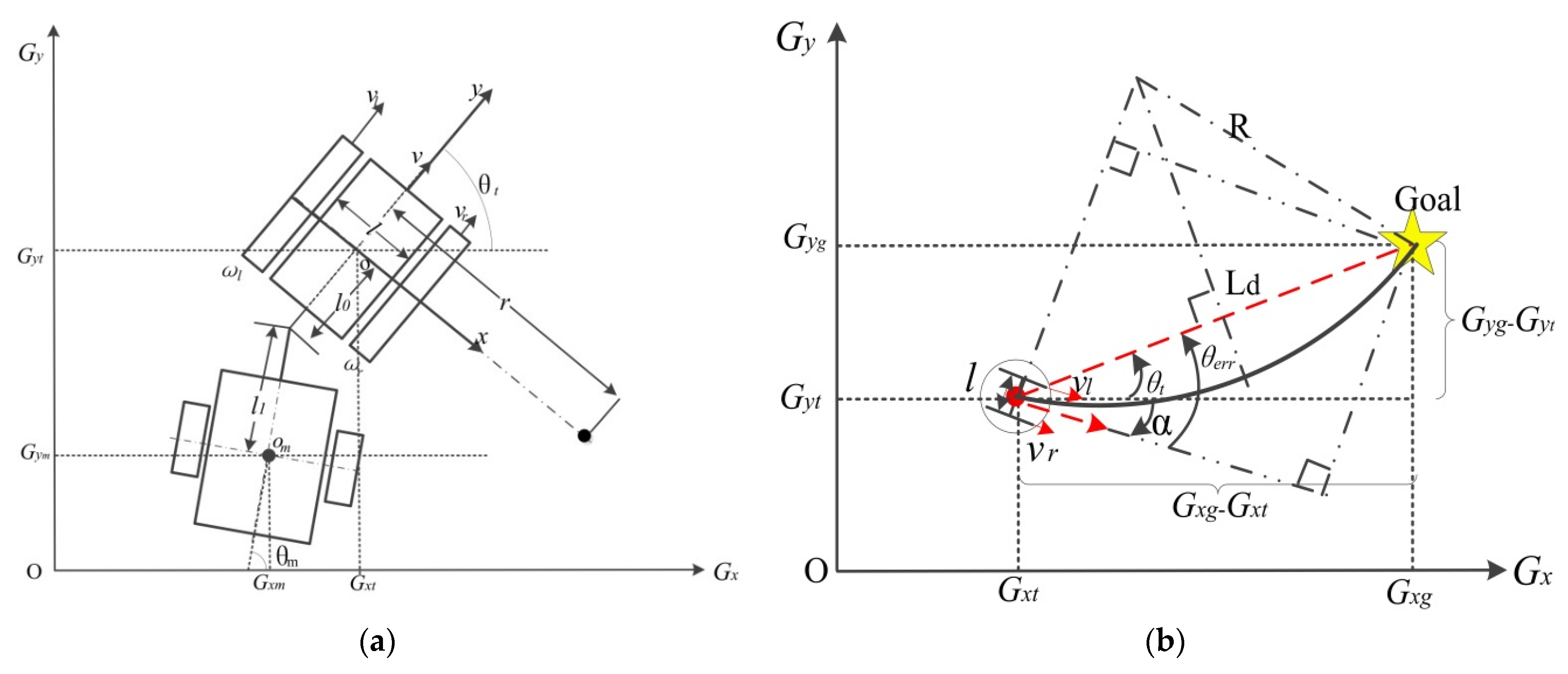
As shown in Figure 11, the distance L of the target feature point from the robot is first calculated using Equation (13), and then the distance Ld between the final robot pre-visual distance point and the robot’s current position point is obtained using Equation (12). Ld is equal to L when Ld is less than the set threshold value of 1 m, or vice versa, is equal to the threshold value of 1 m. The calculated distance Ld is used in Equation (13) to obtain the curvature of the robot walking according to the curve. The crawler robot uses a differential motion model, in which the angular velocities ωl and ωr of the left and right sides of the robot can be determined based on the wheel spacing l, the drive radius r, the angular velocity v, and linear velocity ω from the odometer output in Equation (14). The influence of the angular velocities on both sides can be calculated by Equation (16) to the displacement point coordinates of the crawler robot at the next moment. The actual path of the robot can be controlled by inputting the new displacement point coordinates into Equations (13)–(16).

Figure 11.
Geometric analysis of the pure pursuit algorithm. (a) Traction orchard transporter movement model; (b) geometric analysis of pure pursuit algorithm for differential motion model in the global coordinate system.
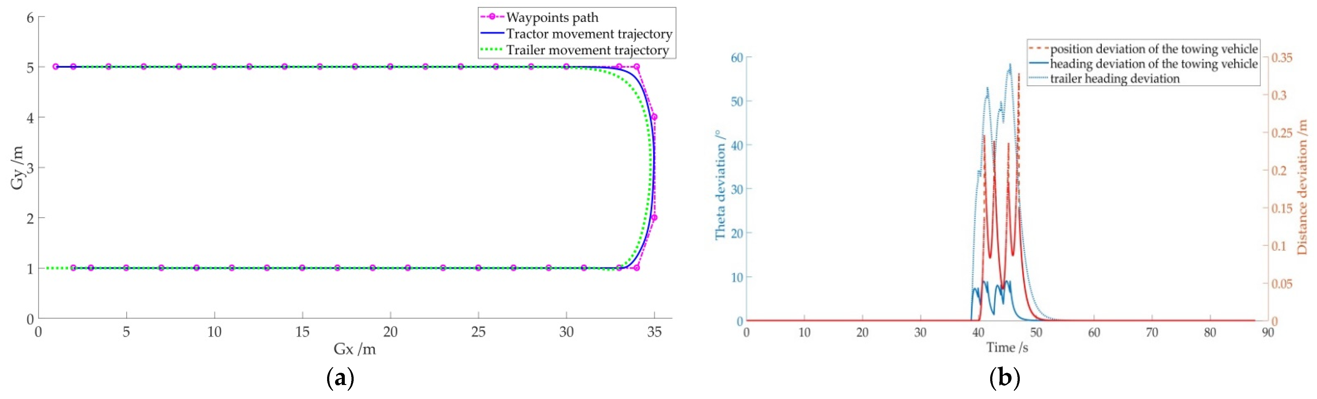
After inputting the ideal path points of the picking and transporting robot walking in the orchard in Matlab, the algorithm is simulated with the robot’s linear velocity v set to 0.5 m/s and angular velocity w to 0.5 m/s. The simulation results are shown in Figure 12. The ideal path point and the simulated tracking path are compared in Figure 12a, where it can be seen that the robot tracks the target point better in a short straight line, while it deviates from the target point at the corner of the turn, but then adjusts it. The angle change and distance difference between the target tracking and the set target point are shown in Figure 12b, where the maximum angle deviation is less than 10 degrees, and the maximum distance deviation is less than 0.35 m. However, the maximum distance deviation occurs at the turning point, when the robot does not operate, and does not affect the operation accuracy.
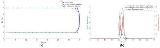
Figure 12.
Simulation of the pure pursuit tracking algorithm for target feature points. (a) Pure tracking algorithm to follow waypoints; (b) tracking algorithm heading and distance deviation.
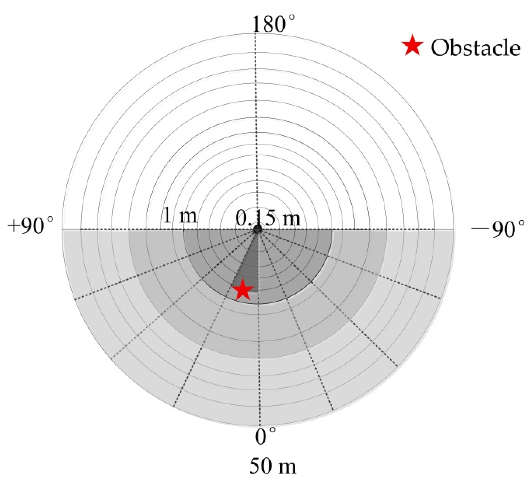
When the robot turns at the ground head relying on the turning point of GNSS for target tracking, to prevent collision between robots, it is necessary to identify the obstacles in front of it. Here, the information of ±3° in the vertical direction, ±90° in the horizontal direction, and scanning distance of [0.15, 10] m in 3-D LIDAR are obtained, and the range is divided into multiple aliquot regions. As shown in Figure 13, when there is an object (red asterisk) blocking any of the aliquot areas, the radar scanning distance is less than 1 m, i.e., the obstacle is judged to exist, the output speed is 0 m/s, and the robot stops sharply. Otherwise, the robot continues to walk.

Figure 13.
Obstacle avoidance schematic.
3. Results
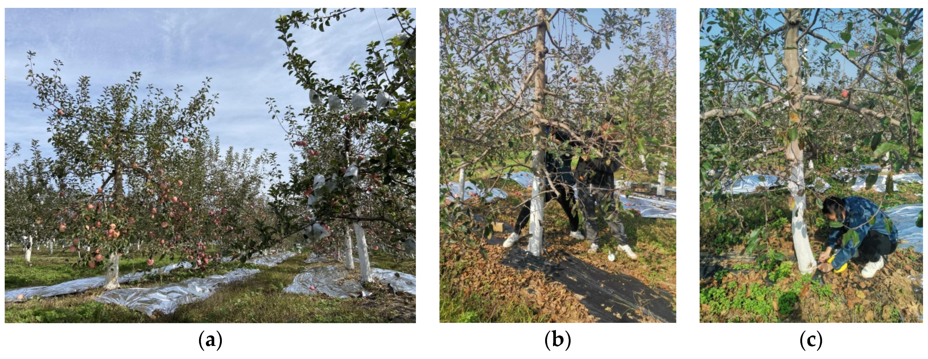
A 389 m2 (47.4 × 8.2 m) non-standard apple cultivation area was selected at the Apple Tree Experimental Demonstration Station of Northwest Agriculture and Forestry University in Baishui County, Shaanxi Province (119°32′45″ E, 35°12′26″ N) from 18 October to 23 October 2021, to test the communication and navigation performance of the orchard picking and transportation robot. The experimental area is shown in Figure 14a, where the apple tree rows are partially interspersed with branches and leaves, a reflective film was laid on the ground near the apple trees, and the ground not covered by the film was covered by weeds. The test area consisted of eight rows of apple trees, mostly of the Red Fuji variety, with about 18 trees planted in each row, spaced about 4 m apart in rows and 2 m apart in plants. In Figure 14b,c, the trunk circumference of apple trees in the test area was measured with a tape measure at 130 cm (stem diameter) [55] and 30 cm (ground diameter) [56] from the ground to obtain the tree diameter data shown in Table 1.

Figure 14.
Apple orchard experimental area environment. (a) Experimental area in Apple Orchard; (b) apple tree diameter at breast height measurement; (c) apple tree diameter at ground measurement.

Table 1.
Apple-tree parameters of the apple orchard.
The detection range of apple tree trunk radius cr was set to [20.5, 26.5] cm based on the average value of the actual measured trunk bottom diameter and trunk diameter.
3.1. Communication Experiment
To verify the reliability of information interaction of the combined harvesting robot in an orchard environment, based on the minimum tracking distance (0.35 m) between the two robots measured in the field and the longest distance (47.4 m) of the fruit tree rows in the test area, an orchard communication test of the combined harvesting robot was designed based on previous literature [38]. The test protocol is shown in Figure 15a.
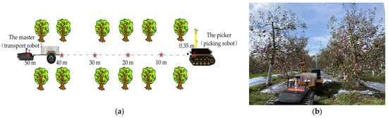
Figure 15.
A combined harvesting robot communication trial. (a) Experimental scheme for master-slave robot orchard communication; (b) combined harvesting robot communication trials in orchards.
After the communication connection was established between the master and slave robots, it was first connected to the Internet Protocol (IP) address of the slave robot via the ssh command, and then 500 packets were sent to the master robots. The unreceived packets were checked on the computers connected to the IP address of the master robot at different distances, then the number of packets received by the slave machine was checked and the packet loss rate was calculated. This test was repeated five times independently. The IP address of the master robot at the time of the test was 192.168.62.2, and the IP address of the slave robot was 192.168.62.30.
When the front end of the slave robot is 0.35 m away from the fruit basket of the master robot, the master robot can receive all the packets, and the number of packets lost and the packet loss rate of the communication system are both zero. The slave robot was then placed at 10, 20, 30, and 40 m from the master robot, which had 1, 2, 4, and 6 packet loss counts, resulting in the packet loss rate of the communication system being 0.2, 0.4, 0.8, and 1.2%, respectively. Finally, the slave robot was placed 50 m from the master robot, where the distance between the master and slave robots is greater than the length of the orchard rows, and the master robot was inside the orchard and the slave robot was outside the orchard. The number and rate of packet loss of this communication system were consistent with the distance interval of the robots at 40 m. It can be seen that the packet loss rate of data interaction within the orchard rows for the joint robots based on the communication system is less than 1.2%, which indicates that the data loss is negligible when the robots are interacting with information in the orchard.
Data on the number of packet losses and packet loss rates for the robotic communication system tests are shown in Table S1 in the Supplementary Information.
3.2. Navigation Experiments
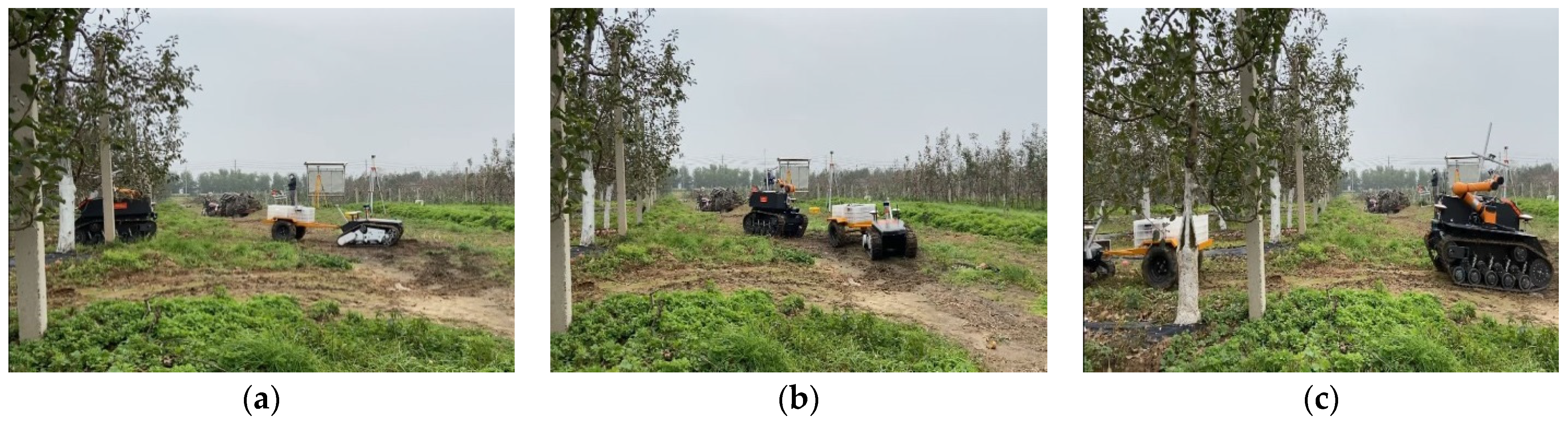
Based on the results of several orchard experiments in the early stage [44,45], the robot walking speed was set to 0.5 m/s in this experiment. According to references [38,57], an experimental scheme of an autonomous navigation system for a combined orchard harvesting robot was designed as shown in Figure 16. The transport (master) and picking (slave) robot of this navigation system starts from the starting point, stops repeatedly between inter-rows of the apple trees, drives out of the rows, turns at the head of the ground, enters the next row of apple trees for operation, and finally stops at the endpoint. The temporary stopping point is the point where the autonomous navigation system of the joint orchard harvesting robot stops in the row of apple trees, and the safety distance threshold between the two robots at this point is 0.35 m. When the combined orchard harvesting robot stops driving, the GNSS coordinate values and heading values provided by the robot are recorded in real-time, the current row spacing values of the apple trees, the distance between the center points of the two robots, the apple trees on the side where the robotic arm is located, and the following distance between the two robots are measured. This stop-drive experiment was repeated three times in the test area. The experimental scenarios are shown in Figure 17.
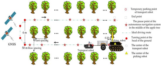
Figure 16.
Experimental scheme for autonomous navigation of the picking and transporting robots.
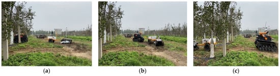
Figure 17.
Picking and transporting robots carrying out autonomous navigation trials in an orchard. (a) Start turning at the head of the ground; (b) picking and transporting robots turn at the same time; (c) start of apple tree in-row navigation.
The distance from the center of the transport robot to the left apple tree (the robot arm is closer to the left apple tree), and the distance from the center of the picking robot to the left apple tree, are measured, respectively, when the master-slave robot is stopped. Then, the spacing between the rows of apple trees on both sides is measured and, finally, the position deviation of the center point of the transport robot from the center point of the apple tree row (cited as the master’s position deviation) and the position deviation of the center of the picking robot from the center point of the apple tree row (cited as the slave’s position deviation) is calculated based on the measured values. The position deviation here is taken as the absolute value of the calculated value, as shown in Tables S2, S3 and S5 in the Supplementary Materials. The master-slave robot stopped 40 times in total. The first 20 times were for the master-slave robot to go from the start point to the turning point within the first row, and the last 20 times for the master-slave robot to go from the turning point to the endpoint within the next row. In the first row, there were apple trees on only one side of the apple tree row at stops 3, 5, 10, 12, 15, and 17, and at stops 2, 4, 6, 9, 11, 13, 15, and 19 in the next row. This shows that relying on the detection of apple tree trunks to achieve stops within the orchard rows is reliable, even for the case of missing apple trees on one side.
The master’s position deviation decreased gradually with the increase in the number of trials, as shown by the decrease in the mean value of the deviation from 0.027 m to 0.02 m. The standard deviation of the deviation decreased from 0.01 m to 0.006 m, indicating a smooth change in position deviation. For example, the position deviation was 0.027 m for the third (missing apple tree) stop in the first trial in row 1, 0.039 m for the fourth stop, and 0.021 m for the fifth (missing apple tree) stop. The same situation occurred successively in the first row and the other unilateral stops in the next row. The maximum value of the position deviation was 0.053 m at the thirteenth stop in the first row and the minimum value is 0.009 m at the ninth stop in the next row. The deviation of the main robot position at both ends of the stop was mostly smaller than the average value. For example, at the first stop in the second row, the position deviation was as low as 0.012 m.
The slave’s position deviation also decreased gradually with increasing number of trials, but the change was not obvious. For example, the mean value of the deviation decreased from 0.037 m to 0.034 m in the first-row trial and from 0.048 m to 0.045 m in the second-row trial, but the mean value of the deviation in the first-row trial was smaller than the deviation in the second-row trial. The standard deviation of the deviation values decreased from 0.02 m to 0.008 m, indicating a relatively smooth variation of the position deviation. Similar to the position deviation of the transport robot, the position deviation of the picking robot was more pronounced when there were one-sided apple trees in the rows. For example, on the first trial in row 1, the position deviation was 0.032 m for third stops, 0.063 m for fourth stops, and 0.02 m for fifth stops. The same situation occurred successively at the first row and the next row other unilateral stopping points. Unlike the transport robot, which has a low position deviation at both ends of the fruit tree rows, the maximum value of the position deviation of the picking robot was 0.397 m at the first stop in the second row, while the minimum value was 0.011 m at the twelfth stop in the second row. For example, the maximum position deviation at the 20th stopping point was 0.019 m, while the average deviation was 0.034 m.
The distance between the center point of the front end of the picking robot and the fruit basket of the transport robot was measured at the stopping point, and then the error of the picking robot following the transport robot in the apple tree rows was calculated according to the safety setting threshold between the robots, where the error was taken as the absolute value of the calculated difference (cite as the following error), as shown in Tables S4 and S5 in the Supplementary Materials. The mean error value fluctuated from 0.01 m to 0.02 m, and the standard deviation of the error varied from 0.007 m to 0.013 m, indicating that the method of maintaining a fixed formation by detecting the position of the fruit basket is effective and that the system operates smoothly when the slave follows the master in the row. Unlike the phenomenon of position deviation variation from the robot, the following error of both robots also appeared to vary significantly in the section with apple trees on both sides. For example, the maximum interval value between robots was 0.007 m at the seventh stop in the first row, 0.034 m at the eighth stops, and 0.022 m at the ninth stops. The same phenomenon also occurred at the sixteenth and seventeenth stopping points in the next row.
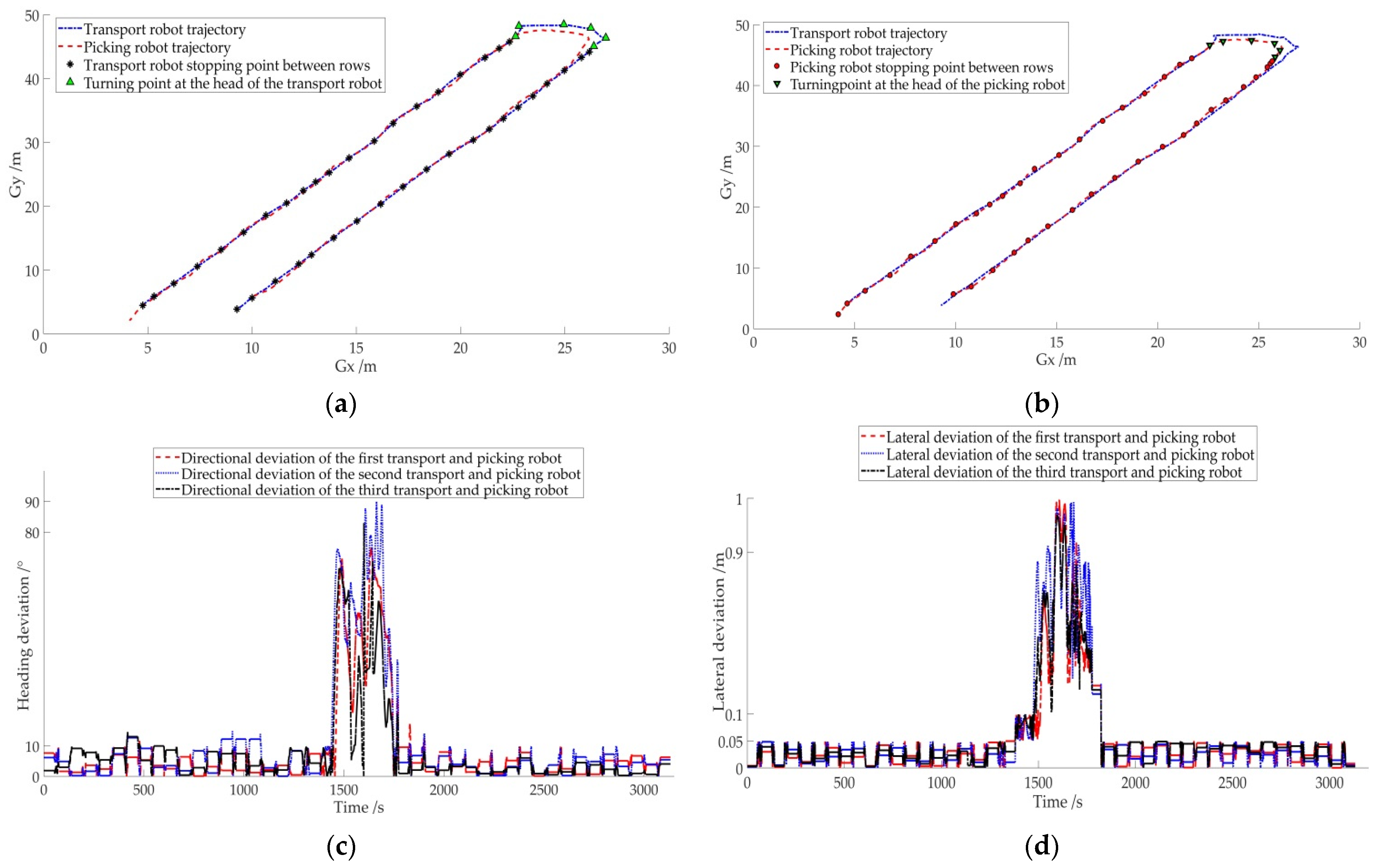
The actual walking paths of the transport robot and the picking robot in the orchard are shown in Figure 18, where the stopping points of the transport robot in this path are shown in Figure 18a and the stopping points of the picking robot in this path are shown in Figure 18b. It can be seen that the routes of the two robots almost overlap when driving between rows, and the intervals between the stopping points are almost the same, but there is a large position error when turning. To analyze the operation of the autonomous navigation system of the combined orchard harvesting robot more visually, the course deviation and lateral deviation between the two robots were calculated and plotted in Figure 18c,d. It is obvious from the figure that when driving at the head of the orchard, the heading deviation of the two robots was mostly within 0.05 m, and the lateral deviation was 10°, with a small variation. While the maximum value of heading angle deviation was less than 90° and the maximum value of lateral deviation was less than 1 m when the ground head turned, and the change was drastic. This is similar to the variation of heading angle and lateral deviation in Figure 12 of the previous simulation experiment.
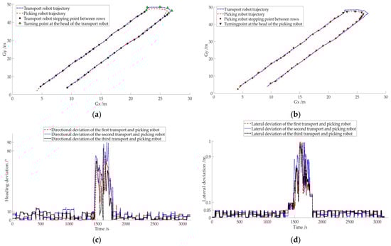
Figure 18.
Results of autonomous navigation experiments with transport and picking robots. (a) Stopping points of the transport robot; (b) stopping points of the picking robot; (c) heading deviation between transport and picking robots; (d) lateral deviation between transport and picking robots.
The above experimental results show that the developed orchard joint harvesting robot autonomous navigation system completes repeated stops between rows of apple trees at a speed of 0.5 m/s and makes continuous turns without collisions.
4. Discussion
The distance between apple tree plants is about 2 m. When the transport or picking robot is between apple tree rows, each driving distance is about one plant distance, and too fast a speed leads to larger inertia when the robot stops, thus affecting the following error of the joint picking autonomous navigation system. At the same time, when the robot speed is too fast, the central control unit cannot provide the transport robot with accurate positioning point information in the middle of the apple tree rows. After a preliminary practical test, the driving speed of the robot was set to 0.5 m/s during the experiment.
- (1)
- The experimental results of the communication system showed that the master-slave robot can send messages via point-to-point in the orchard. Although the information interaction between master and slave robots showed communication packet loss as the communication distance increased, when the distance between robots (50 m) was greater than the maximum distance of a single row of apple trees (47.4 m), the packet loss rate of the communication system was less than 1.2% and the number of packet losses was negligible. This indicates that when the combined harvesting robots traveled in the middle of the apple tree rows within 50 m, there was little medium to affect the communication between the robots in the space above the weeds under the tree canopy. Although the distance between robots changes during travel, the distance interval is typically less than 10 m, which means that the master-slave robot can maintain operation within the communication distance of a strong signal. Thus, a Wi-Fi-based master-slave robot communication system can meet the communication needs of collaborative operations in orchards.
- (2)
- The position deviation values of the master and slave robots decreased as the number of trials increased when the combined harvesting robot was driving in the orchard rows, For example, the position deviation of the master robot decreased from 0.027 m to 0.02 m, which may be because the robot’s tracks flattened the weeds and floating soil on the ground during repeated driving in the orchard, thus reducing soil-induced slippage. However, the average value of position deviation of the slave robot increased from 0.037 m to 0.048 m, which may be because during the turning process the master-slave robot switched to command navigation, and as the master robot pulled the trailer to turn, the heading of the trailer changed significantly, resulting in a larger angle of heading change when the robot turned from the ground for the next row (the heading difference between the master-slave robot was greater than 10° less than 90°). This, in turn affects the size of the position deviation. For example, at the first stop in the next row, the maximum value of the position deviation was 0.397 m.The position deviations of the master and slave robots varied considerably at the stopping point, which was either the next or the previous point of the one-sided apple tree stopping point. For example, in the first row, the maximum value of position deviation was 0.019 m at station 12 (lack of apple trees) and 0.053 m at station 13, which could be due to the change in canopy density from dense to sparse, or from sparse to dense. This variation led to deviations in the trunk centroids identified by the master robot and caused position deviations in the slave following the master. The position deviations at both ends of the apple tree rows were mostly smaller than the average deviation, probably because there was no interference from other apple trees and the trunks of the apple trees were thick enough for the master robot to identify the trunks. For instance, the maximum position deviation in the first row was 0.025 m, which is 0.002 m less than the average position error value of 0.027 m. The same situation occurred within the apple tree rows. For example, in the second row, the minimum value of position deviation for station 9 (the missing apple tree) was 0.009 m.
- (3)
- When the master-slave robot travels at a fixed speed of 0.5 m/s, there may be incomplete filtering of ground points or too many filtering points due to the close distance between the master and the slave robot and the small height of the apple basket, resulting in errors when the slave robot extracts the apple basket feature points and fits the fruit basket center-of-mass points. For example, in the first row, the maximum following error was 0.044 m for the fourth stopping point and 0.004 m for the third stopping point (with fruit trees on one side). Similarly, the following error on entering or leaving a row of fruit trees was less than the error mean or close to the error mean, which may be due to significant changes in the ground,. The algorithm can easily distinguish between ground points and fruit baskets. For example, the maximum following error for the 20th parking point in row 1 was 0.019 m, which is 0.001 m larger than the error mean of 0.018 m.
The almost overlapping driving trajectories of the master-slave robot show that the pure tracking algorithm can ensure that the robots follow the waypoints in a relatively stable manner. However, due to the different distance lengths, and directions provided by the artificially selected GNSS steering points, a large angle change between the trailer and the tractor behind the master robot at the ground head turn led to a large deviation between the motion trajectory of the slave robot (tracking the navigation points of the trailer motion model) and that of the master robot. The experimental results show that the maximum lateral deviation of the master-slave robot during the turn was less than 1 m, the minimum lateral deviation was greater than 0.3 m, the maximum heading deviation was less than 90°, and the minimum heading deviation was greater than 10°.
To reduce the lateral deviation and heading deviation of the master-slave robot at the ground head turn, future research will focus on optimizing the pure tracking algorithm, designing fuzzy PID control rules based on the experimentally derived adjustment range of the robot’s lateral deviation and heading deviation, and using this rule and the pure tracking algorithm to enable the robot to adjust the turning radius according to the change in waypoint distance. At the same time, the robot tracking speed may be slowly increased or decreased at the beginning and end of each waypoint tracking segment to reduce the robot’s inertia.
5. Conclusions
Based on the process of commercial apple harvesting, our research developed an autonomous navigation system for a combined orchard harvesting robot using two master-slave navigation methods, Wi-Fi point-to-point communication technology, target feature extraction, and pure tracking control technology, in which the transport robot is the master and the picking robot is the slave. The performance of this combined harvesting robot navigation system was verified through orchard trials.
The experimental results show that the packet loss rate of the communication system was less than 1.2% when the interval distance of the joint harvesting robots was within 50 m, which meets the communication requirements of the master and slave robots in the orchard. The combined harvesting robot achieved the stop-drive function according to the apple tree planting situation when driving in the row at a speed of 0.5 m/s, and the system ran smoothly. However, the impact of the change in trailer heading when the master vehicle was towing the trailer around a turn resulted in a significant error when the slave vehicle entered the next row and came to a stop. The error value gradually decreased after changing the master-slave navigation method and can be used for in-row cooperative operations. The maximum value of the position error of the master robot was 0.053 m, the minimum value was 0.008 m, the mean value of the error was 0.024 m, and the standard deviation of the error was 0.009 m. The maximum value of the position error of the slave robot was 0.397 m, the minimum value was 0.011 m, the mean value of the error was 0.041 m, and the standard deviation of the error was 0.056 m. The safety distance between master and slave robots was within the set threshold (0.35 m), where the maximum value of the following error was 0.044 m, the mean value of error was 0.013 m, and the standard deviation of error was 0.01 m. Therefore, the system can meet the demands of cooperative operation without collision. The combined harvesting robots could achieve smooth turns according to commanded navigation during the turns, but the course deviation (greater than 10° less than 90°) and lateral deviation (greater than 0.3 m less than 1 m) between robots during the turns were largely due to the trailer motion model.
6. Patents
A dual navigation mode orchard joint harvesting robot autonomous navigation system V1.0.
Supplementary Materials
The following are available online at https://www.mdpi.com/article/10.3390/rs14030675/s1. Section 3 results in this paper, and experimental data involving communication and control system tests, are shown in the following Table. Among them, Table S1 shows the experimental data of the packet loss rate of the communication test, Table S2 shows the data of the position deviation calculated by measurement when the master robot was stopped in the orchard row, Table S3 shows the data of the position deviation calculated by measurement when the slave robot was stopped in the orchard row, and Table S4 shows the data of the deviation of the distance between the master and slave robots from the set threshold. Table S5 shows a summary of the maximum, minimum, mean, and standard deviation for Tables S2–S4.
Author Contributions
Methodology, W.M., Z.L. and F.Y.; software, W.M.; validation, W.M., H.L. and W.H.; data curation, W.M.; writing—original draft preparation, W.M.; writing—review and editing, W.M., H.L., Z.L. and F.Y.; supervision, W.M., H.L., Z.L. and F.Y.; project administration, F.Y. All authors have read and agreed to the published version of the manuscript.
Funding
This research received funding from the Major Science and Technology Project of Shaanxi Province of China (Program No. 2020zdzx03-04-01) and the Technology innovation guidance special project of Shaanxi Province of China (Program No.2021QFY08-05).
Institutional Review Board Statement
The project supporting the research of this paper is to study agricultural machinery and equipment for apple orchards, and the research does not involve humans or animals.
Informed Consent Statement
The study in the paper did not involve humans or animals.
Data Availability Statement
Please refer to suggested data in the Supplementary Materials.
Acknowledgments
We also thank the critical comments and suggestions from the anonymous reviewers for improving the manuscript.
Conflicts of Interest
The authors declare no conflict of interest.
References
- George Vougioukas, S.; Spanomitros, Y.; Slaughter, D. Dispatching and Routing of Robotic Crop-transport Aids for Fruit Pickers using Mixed Integer Programming. In Proceedings of the American Society of Agricultural and Biological Engineers, Dallas, TX, USA, 29 July–1 August 2012; pp. 3423–3432. [Google Scholar]
- Nguyen, T.T.; Kayacan, E.; De Baedemaeker, J.; Saeys, W. Task and motion planning for apple harvesting robot. In Proceedings of the 4th IFAC Conference on Modelling and Control in Agriculture, Horticulture and Post Harvest Industry, Agricontrol, Espoo, Finland, 28–30 August 2013; pp. 247–252. [Google Scholar]
- Liu, J. Research Progress Analysis of Robotic Harvesting Technologies in Greenhouse. Trans. Chin. Soc. Agric. Mach. 2017, 48, 1–18. [Google Scholar] [CrossRef]
- Sa, I.; Ge, Z.; Dayoub, F.; Upcroft, B.; Perez, T.; McCool, C. Deepfruits: A fruit detection system using deep neural networks. Sensors 2016, 16, 1222. [Google Scholar] [CrossRef] [PubMed] [Green Version]
- Silwal, A.; Davidson, J.R.; Karkee, M.; Mo, C.; Zhang, Q.; Lewis, K. Design, integration, and field evaluation of a robotic apple harvester. J. Field Robot. 2017, 34, 1140–1159. [Google Scholar] [CrossRef]
- Sarabu, H.; Ahlin, K.; Hu, A. Graph-Based Cooperative Robot Path Planning in Agricultural Environments. In Proceedings of the IEEE/ASME International Conference on Advanced Intelligent Mechatronics (AIM), Hongkong, China, 8–9 July 2019; pp. 519–525. [Google Scholar]
- Baxter, P.; Cielniak, G.; Hanheide, M.; From, P. Safe Human-Robot Interaction in Agriculture. In Proceedings of the Companion of the 2018 ACM/IEEE International Conference on Human-Robot Interaction, Chicago, IL, USA, 5–8 March 2018; pp. 59–60. [Google Scholar]
- Shamshiri, R.R.; Weltzien, C.; Hameed, I.A.; Yule, I.J.; Grift, T.E.; Balasundram, S.K.; Pitonakova, L.; Ahmad, D.; Chowdhary, G. Research and development in agricultural robotics: A perspective of digital farming. Int. J. Agric. Biol. Eng. 2018, 11, 1–14. [Google Scholar] [CrossRef]
- Salah, K.; Chen, X.; Neshatian, K.; Pretty, C. A hybrid control multi-agent cooperative system for autonomous bin transport during apple harvest. In Proceedings of the 13th IEEE Conference on Industrial Electronics and Applications (ICIEA), Wuhan, China, 31 May–2 June 2018; pp. 644–649. [Google Scholar]
- Seyyedhasani, H.; Peng, C.; Jang, W.-J.; Vougioukas, S.G. Collaboration of human pickers and crop-transporting robots during harvesting–Part II: Simulator evaluation and robot-scheduling case-study. Comput. Electron. Agric. 2020, 172, 105323. [Google Scholar] [CrossRef]
- Mao, W.; Liu, Z.; Liu, H.; Yang, F.; Wang, M. Research Progress on Synergistic Technologies of Agricultural Multi-Robots. Appl. Sci. 2021, 11, 1448. [Google Scholar] [CrossRef]
- Zhang, M.; Ji, Y.; Li, S.; Cao, R.; Xu, H.; Zhan, Z. Research Progress of Agricultural Machinery Navigation Technology. Trans. Chin. Soc. Agric. Mach. 2020, 51, 1–18. [Google Scholar] [CrossRef]
- Noguchi, N.; Will, J.; Reid, J.; Zhang, Q. Development of a master-slave robot system for farm operations. Comput. Electron. Agric. 2004, 44, 1–19. [Google Scholar] [CrossRef]
- Shearer, S.A.; Pitla, S.K.; Luck, J.D. Trends in the automation of agricultural field machinery. In Proceedings of the 21st Annual Meeting of the Club of Bologna, Bologna, Italy, 13–14 November 2010; pp. 1–15. [Google Scholar]
- Moorehead, S.; Wellington, C.; Gilmore, B.; Vallespi, C. Automating Orchards: A System of Autonomous Tractors for Orchard Maintenance. In Proceedings of the 2012 IEEE/RSJ International Conference on Intelligent Robots & Systems (IROS), Vilamoura, Algarve, Portugal, 7–12 October 2012; pp. 1–8. [Google Scholar]
- Gonzalez-de-Santos, P.; Ribeiro, A.; Fernandez-Quintanilla, C.; Lopez-Granados, F.; Brandstoetter, M.; Tomic, S.; Pedrazzi, S.; Peruzzi, A.; Pajares, G.; Kaplanis, G.; et al. Fleets of robots for environmentally-safe pest control in agriculture. Precis. Agric. 2017, 18, 574–614. [Google Scholar] [CrossRef]
- Kim, J.; Son, H.I. A Voronoi Diagram-Based Workspace Partition for Weak Cooperation of Multi-Robot System in Orchard. IEEE Access 2020, 8, 20676–20686. [Google Scholar] [CrossRef]
- Ju, C.; Son, H.I. Modeling and Control of Heterogeneous Agricultural Field Robots Based on Ramadge-Wonham Theory. IEEE Robot. Autom. Lett. 2020, 5, 48–55. [Google Scholar] [CrossRef]
- Mao, W.; Liu, H.; Wang, D.; Yang, F.; Liu, Z. An Improved AODV Routing Protocol for Multi-Robot Communication in Orchard. Smart Agric. 2021, 3, 96. [Google Scholar] [CrossRef]
- Fei, Z. Autonomous Co-Robotic Orchard Platform for Improved Fruit Harvesting Efficiency. Ph.D. Thesis, University of California, Davis, CA, USA, 2020. [Google Scholar]
- Zhang, J.; Maeta, S.; Bergerman, M.; Singh, S. Mapping orchards for autonomous navigation. In Proceedings of the American Society of Agricultural and Biological Engineers Annual International Meeting ASABE, Montreal, QC, Canada, 13–16 July 2014; pp. 31–39. [Google Scholar]
- Bergerman, M.; Maeta, S.M.; Zhang, J.; Freitas, G.M.; Hamner, B.; Singh, S.; Kantor, G. Robot Farmers Autonomous Orchard Vehicles Help Tree Fruit Production. IEEE Robot. Autom. Mag. 2015, 22, 54–63. [Google Scholar] [CrossRef]
- Shalal, N.; Low, T.; McCarthy, C.; Hancock, N. Orchard mapping and mobile robot localization using on-board camera and laser scanner data fusion—Part A: Tree detection. Comput. Electron. Agric. 2015, 119, 254–266. [Google Scholar] [CrossRef]
- Bell, J.; MacDonald, B.A.; Ahn, H.S. Row following in pergola structured orchards. In Proceedings of the IEEE/RSJ International Conference on Intelligent Robots and Systems IROS, Daejeon, Korea, 9–14 October 2016; pp. 640–645. [Google Scholar]
- Lepej, P.; Rakun, J. Simultaneous localization and mapping in a complex field environment. Biosyst. Eng. 2016, 150, 160–169. [Google Scholar] [CrossRef]
- Blok, P.; Suh, H.; van Boheemen, K.; Kim, H.-J.; Gookhwan, K. Autonomous In-Row Navigation of an Orchard Robot with a 2D LIDAR Scanner and Particle Filter with a Laser-Beam Model. J. Inst. Control. Robot. Syst. 2018, 24, 726–735. [Google Scholar] [CrossRef]
- Jones, M.H.; Bell, J.; Dredge, D.; Seabright, M.; Scarfe, A.; Duke, M.; MacDonald, B. Design and testing of a heavy-duty platform for autonomous navigation in kiwifruit orchards. Biosyst. Eng. 2019, 187, 129–146. [Google Scholar] [CrossRef]
- Zhang, S.; Guo, C.; Gao, Z.; Sugirbay, A.; Chen, J.; Chen, Y. Research on 2d laser automatic navigation control for the standardized orchard. Appl. Sci. 2020, 10, 2763. [Google Scholar] [CrossRef]
- Liu, X.; Zhang, C.; Zhang, H.; Yang, S.; Jiang, S.; Zheng, Y.; Su, D.; Wan, C. Inter-row automatic navigation method by combining least square and SVM in forestry. Trans. Chin. Soc. Agric. Eng. 2021, 37, 157–164. [Google Scholar] [CrossRef]
- Liu, W.; He, X.; Liu, Y.; Wu, Z.; Yuan, C.; Liu, L.; Qi, P.; Li, T. Navigation method between rows for orchard based on 3D LiDAR. Trans. Chin. Soc. Agric. Eng. 2021, 37, 165–174. [Google Scholar] [CrossRef]
- Bayar, G.; Bergerman, M.; Koku, A.B.; Konukseven, E.I. Localization and control of an autonomous orchard vehicle. Comput. Electron. Agric. 2015, 115, 118–128. [Google Scholar] [CrossRef] [Green Version]
- Cui, W.; Ding, L. Research on path planning of mobile picking robot based visual navigation and RBF. J. Agric. Mech. Res. 2016, 38, 234–238. [Google Scholar]
- Guo, S.; Zhang, L.; Liu, Z. Design of a grape picking root with high accuracy and self-guided positioning. J. Agric. Mech. Res. 2016, 38, 20–24. [Google Scholar]
- Li, X.; Li, L.; Li, N. Independent positioning and navigation design of picking robot based on RFID and WSN. J. Agric. Mech. Res. 2017, 39, 215–218. [Google Scholar]
- Sun, Y.; Sun, J.; Zhao, R.; Li, S.; Zhang, M.; Li, H. Design and System Performance Analysis of Fruit Picking Robot. Trans. Chin. Soc. Agric. Mach. 2019, 50, 8–14. [Google Scholar]
- Ding, Y.; Wang, Z.; Lin, X.; Bi, W.; Lin, X.; Xue, J. Heading Control System of Autonomous Following Vehicle. Trans. Chin. Soc. Agric. Mach. 2015, 46, 8–13. [Google Scholar] [CrossRef]
- Bi, W.; Zhang, H.; Qu, Z.; Ding, Y.; Yu, H.; Wang, B. Design of autonomous following system for master-slave vehicles operating in orchard based on binocular stereo vision. J. Hunan Agric. Univ. Nat. Sci. 2016, 344–348. [Google Scholar] [CrossRef]
- Li, S.; Xu, H.; Ji, Y.; Cao, R.; Zhang, M.; Li, H. Development of a following agricultural machinery automatic navigation system. Comput. Electron. Agric. 2019, 158, 335–344. [Google Scholar] [CrossRef]
- Zhang, C.; Noguchi, N.; Yang, L. Leader–follower system using two robot tractors to improve work efficiency. Comput. Electron. Agric. 2016, 121, 269–281. [Google Scholar] [CrossRef]
- Bai, X.; Wang, Z.; Hu, J.; Gao, L.; Xiong, F. Harvester Group Corporative Navigation Method Based on Leader-Follower Structure. Trans. Chin. Soc. Agric. Mach. 2017, 48, 14–21. [Google Scholar] [CrossRef]
- Zhang, W.; Zhang, Z.; Luo, X.; He, J.; Hu, J.; Yue, B. Position-velocity coupling control method and experiments for longitudinal relative position of harvester and grain truck. Trans. Chin. Soc. Agric. Eng. 2021, 37, 1–11. [Google Scholar] [CrossRef]
- Zhang, W.; Wan, P.; Wang, T.; Cai, S.; Chen, Y.; Jin, X.; Yan, G. A Novel Approach for the Detection of Standing Tree Stems from Plot-Level Terrestrial Laser Scanning Data. Remote Sens. 2019, 11, 211. [Google Scholar] [CrossRef] [Green Version]
- Oveland, I.; Hauglin, M.; Giannetti, F.; Schipper Kjørsvik, N.; Gobakken, T. Comparing Three Different Ground Based Laser Scanning Methods for Tree Stem Detection. Remote Sens. 2018, 10, 538. [Google Scholar] [CrossRef] [Green Version]
- Liu, Z.; Wang, X.; Ren, Z.; Mao, W.; Yang, F. Crawler tractor navigation path tracking control algorithm based on virtual radar model. Trans. Chin. Soc. Agric. Mach. 2021, 52, 375–385. [Google Scholar]
- Mao, W.; Heng, L.; Wang, X.; Yang, F.; Liu, Z.; Wang, Z. Design and experiment of a dual navigation mode orchard transport robot. Trans. Chin. Soc. Agric. Mach. 2022; Accepted. [Google Scholar]
- Zhang, M.; Fu, R.; Guo, Y.; Shi, Y.; Cheng, W. Road segmentation method based on irregular three dimensional point cloud. J. Jilin Univ. Eng. Technol. Ed. 2017, 47, 8. [Google Scholar] [CrossRef]
- Su, Y.; Wang, T.; Shao, S.; Yao, C.; Wang, Z. GR-LOAM: LiDAR-based sensor fusion SLAM for ground robots on complex terrain. Robot. Auton. Syst. 2021, 140, 103759. [Google Scholar] [CrossRef]
- Chen, S.W.; Nardari, G.V.; Lee, E.S.; Qu, C.; Liu, X.; Romero, R.A.F.; Kumar, V. Sloam: Semantic lidar odometry and mapping for forest inventory. IEEE Robot. Autom. Lett. 2020, 5, 612–619. [Google Scholar] [CrossRef] [Green Version]
- Straub, J.; Reiser, D.; Griepentrog, H.W. Approach for modeling single branches of meadow orchard trees with 3D point clouds. arXiv 2021, arXiv:2104.05282. [Google Scholar] [CrossRef]
- Zhang, M.; Miao, Y.; Qiu, R.; Ji, Y.; Li, H.; Li, M. Maize Leaf Area Index Measurement Based on Vehicle 3D LiDAR. Trans. Chin. Soc. Agric. Mach. 2019, 50, 12–21. [Google Scholar] [CrossRef]
- Hu, G.; Konog, W.; Qi, C.; Zhang, S.; Pu, L.; Zhou, J.; Chen, J. Optimization of the navigation path for a mobile harvesting robot in orchard enviroment. Trans. Chin. Soc. Agric. Eng. 2021, 37, 175–184. [Google Scholar] [CrossRef]
- Westling, F.; Underwood, J.; Bryson, M. Graph-based methods for analyzing orchard tree structure using noisy point cloud data. Comput. Electron. Agric. 2021, 187, 106270. [Google Scholar] [CrossRef]
- Zhang, W.; Qi, J.; Wan, P.; Wang, H.; Xie, D.; Wang, X.; Yan, G. An Easy-to-Use Airborne LiDAR Data Filtering Method Based on Cloth Simulation. Remote Sens. 2016, 8, 501. [Google Scholar] [CrossRef]
- Gong, J.; Liu, K.; Qi, J. Model Predictive Control for Self-Driving Vehicles; Beijing University of Technology Press: Beijing, China, 2020. [Google Scholar]
- Zhang, Y. General Theory of Fruit Tree Cultivation; China Agricultural Press: Beijing, China, 2011; pp. 283–303. [Google Scholar]
- Tao, S.; Zhao, D. Rapid parametric modeling of geometry structure for trees. J. Beijing For. Univ. 2013, 35, 97–101. [Google Scholar] [CrossRef]
- Han, J.-H.; Park, C.-H.; Kwon, J.H.; Lee, J.; Kim, T.S.; Jang, Y.Y. Performance Evaluation of Autonomous Driving Control Algorithm for a Crawler-Type Agricultural Vehicle Based on Low-Cost Multi-Sensor Fusion Positioning. Appl. Sci. 2020, 10, 4667. [Google Scholar] [CrossRef]


Publisher’s Note: MDPI stays neutral with regard to jurisdictional claims in published maps and institutional affiliations. |
© 2022 by the authors. Licensee MDPI, Basel, Switzerland. This article is an open access article distributed under the terms and conditions of the Creative Commons Attribution (CC BY) license (https://creativecommons.org/licenses/by/4.0/).