Abstract
This article investigates channel phase mismatch calibration during the application of displaced-phase-center antenna (DPCA) in dual-channel sliding spotlight synthetic aperture radar (SAR) for ground moving target indication (GMTI). In sliding spotlight SAR, the utilization of beam progressive sweeping in azimuth causes antenna phase centers to be misaligned from the sensor path, resulting in the phase mismatch between channels. Then, spatial channel co-registration required in the DPCA cannot be achieved directly by an azimuth time shift. In this study, a calibration method based on scanning geometry of the dual-channel sliding spotlight SAR is developed to address this issue. Moreover, the effect of the phase mismatch calibration on the estimation of azimuth time difference between the two channels is derived and analyzed in depth. The clutter suppression results processed from experimental data acquired by a C-band dual-channel SAR system (Gaofen-3) operated in sliding spotlight mode are shown for the first time to demonstrate the effective phase mismatch calibration.
1. Introduction
In the synthetic aperture radar (SAR) community, wide unambiguous imaging of the earth’s surface with high resolution has always been one of the most important topics. With the use of phased array antennas, a variety of ground observation modes have been developed for different applications [1,2]. The sliding spotlight mode is widely applied to achieve very-high-resolution imaging [3]. This mode is characterized by beam progressive sweeping in azimuth to increase the illumination interval for providing a higher azimuth resolution than that of stripmap mode, without swath width loss in range. Furthermore, it provides a larger azimuth swath than the staring spotlight mode [4,5]. The antenna beam is steered about a virtual point under the ground in a manner to realize a sliding footprint on the ground, which is a useful trade-off between the stripmap mode and the staring spotlight mode in various civilian and military applications [6,7].
Moreover, SAR systems that combine the azimuth multichannel technology and the sliding spotlight mode can not only obtain high-resolution images, but also have great potential in ground moving target indication (GMTI). They can meet the demand of long-time monitoring, better detection capability and high-resolution imaging of moving targets. It can serve tasks such as recognition and interpretation of moving targets and prediction of motion trajectories. In addition, the multi-aspect observation can help alleviate the problem of moving targets being blocked. The geometry of a dual-channel spaceborne SAR system operated in sliding spotlight mode is shown in Figure 1. Multiple antennas are placed along the track to provide spatial degrees of freedom for suppressing the background clutter. Nevertheless, the research on multichannel sliding spotlight SAR GMTI is lacking at present [8,9,10]. Therefore, this letter firstly studies the channel phase mismatch calibration on the processing of the dual-channel sliding spotlight SAR data with displaced-phase-center antenna (DPCA) [11,12,13].
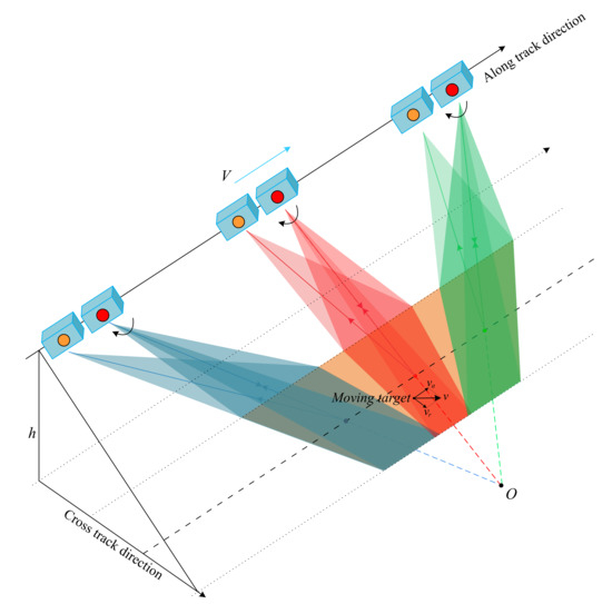
Figure 1.
Geometry of a dual-channel spaceborne SAR system operated in sliding spotlight mode.
The DPCA is a classic algorithm for clutter suppression in dual-channel stripmap SAR-GMTI, which is a simple complex subtraction between the two spatially co-registered channels to cancel clutter. The clutter Doppler bandwidth is sharply reduced, and the moving targets can be detected in the final DPCA image. However, the azimuth beam sweeping causes the two channels to not be directly canceled. In the dual-channel stripmap SAR systems, it is assumed that all the antenna phase centers are aligned with the sensor path during system operation. Then, the spatial channel co-registration in the azimuth of the DPCA method can be achieved by an azimuth time shift, and the background clutter can be suppressed by the channel cancellation. Nevertheless, when a SAR system operates in sliding spotlight mode, the antenna phase centers will be misaligned from the sensor path due to the beam steering. This phenomenon called antenna phase center fluctuation (APCF) [14,15] will cause additional phase mismatch between the two channels, which should be calibrated to ensure clutter suppression in sliding spotlight SAR-GMTI.
In this work, the regularity of the APCF-induced phase mismatch between channels is investigated, and the mismatch is quantified from the perspective of the beam steering geometry of dual-channel sliding spotlight SAR. After the phase mismatch calibration, the APCF can be removed, and the antenna phase centers of dual-channel sliding spotlight SAR are proved to be re-aligned with the sensor path. Then, the two channels can be co-registered spatially by an azimuth time shift. However, the proposed phase mismatch calibration makes the time shift different from that of the dual-channel stripmap SAR system. Accordingly, detailed analyses and derivations of the spatial channel co-registration after the phase mismatch calibration are conducted to illustrate this issue.
The part reason that GMTI in multichannel sliding spotlight operation has not been sufficiently investigated is the lack of actual SAR system and field-collected SAR data. Consequently, we carried out an experiment in June 2021 to acquire the dual-channel sliding spotlight SAR data with the spaceborne Gaofen-3 SAR satellite as the experiment platform. The clutter suppression results of experimental data are shown for the first time to verify the effective phase mismatch calibration.
The rest of this letter is organized as follows. Section 2.1 analyzes and quantizes the phase mismatch caused by the APCF in dual-channel sliding spotlight SAR. The antenna phase centers are proved to be re-aligned with the sensor path after the phase mismatch calibration from the Doppler centroid variation perspective. Moreover, the effect of the phase mismatch calibration on azimuth time difference estimation between the two channels are presented in Section 2.2 to ensure the implementation of the spatial channel co-registration. In Section 3, results of azimuth time difference estimation and GMTI based on experimental data from Gaofen-3 are provided to demonstrate the effective phase mismatch calibration. The concluding remarks are presented in Section 4.
2. Phase Mismatch Calibration for Dual-Channel Sliding Spotlight SAR-GMTI
This section first analyses and quantifies the APCF-induced phase mismatch caused by the beam progressive sweeping in azimuth in dual-channel sliding spotlight SAR systems, and the spatial channel co-registration in DPCA after the phase mismatch calibration is explored later.
2.1. Phase Mismatch Caused by APCF
Modern SAR systems are usually equipped with advanced phased array antennas, which adjust the phase offsets for antenna units to achieve electronically controlled beam steering through phase shifters without physically rotating the antenna, and they are more precise and flexible than traditional mechanical scanning antennas. Figure 2 shows the applied phased array antenna of our system. The entire azimuth antenna is used as the transmitter, and all array elements are divided into two receive channels, and one reference phase point is selected and located at the edge of antenna, where the applied phase is constant during the beam steering. The phase applied to other array units is precisely calculated according to the beam direction.
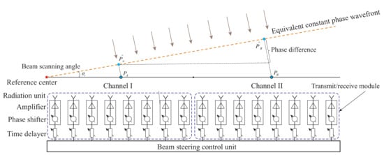
Figure 2.
Azimuth sketch of the applied phased-array antenna in our experiment platform.
Figure 3 shows the geometry of beam steering in azimuth of a dual-channel sliding spotlight SAR. The direction of the equivalent constant phase wavefront is adjusted by applying different phase offsets to array elements to point to a virtual point O located under the ground. Then, the two channels require continuously changed phase offsets to steer the beam, causing the antenna phase centers to be misaligned from the sensor path, and the geometry is shown in Figure 3a. This phenomenon is regarded as APCF [14,15]. The two receive antenna centers are and , respectively. The phase difference in azimuth applied by the phase shifters between the two channels relative to the reference phase point is obtained as
where D represents the physical distance between the receive channels, is the sensor wavelength, and represents the beam scanning angle. The first antenna (red) is used as the reference channel, so its phase center coincides with the antenna center . In sliding spotlight mode, the phase center of second antenna is . Figure 3b shows the phase mismatch in range caused by the APCF. When the target T is not in the scene center, the resulting mismatch is defined as , which is also varied along with the beam scanning angle. Therefore, the total phase mismatch varies with range and azimuth is obtained from the scanning geometry, i.e.,
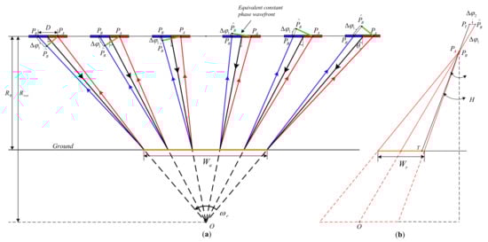
Figure 3.
Geometry of beam azimuth rotation in a dual-channel SAR operated in sliding spotlight mode. () The antenna phase centers movement along the sensor path due to the beam progressive sweeping, () the phase mismatch in range caused by APCF (side-view).
Performing phase mismatch calibration based on Equation (2) is not conducive to the subsequent derivations. Moreover, compared to the azimuth phase mismatch (), the phase mismatch from range () is relatively slight, which can be ignored, according to the scanning geometry in Figure 3. Therefore, Equation (2) can be simplified as
where denotes the azimuth time, is the rotation rate of azimuth beam scanning, indicates the nearest slant range between the sensor and the ground, and represents the slant range of the target (T). In single channel sliding spotlight SAR systems, the reference phase point can be set at the center of the azimuth antenna and coincide with the phase center. In this scenario, the phenomenon of APCF can be theoretically avoided, and the effect on imaging caused by the beam progressive sweeping can be ignored [15]. However, for dual-channel sliding spotlight SAR-GMTI, the phase mismatch will cause the time difference between channels cannot be estimated accurately. Then, the two channels cannot be spatially co-registered in azimuth, which is discussed as below.
Before the phase calibration, the cross-correlation coefficient between the two channels [16,17] can be expressed as
where represents the speed of the SAR platform, is the Doppler centroid that varies with the azimuth time, and represent the signals of two channels, is the azimuth inverse Fourier transform of the antenna’s two-way power pattern. indicates the constant phase error between the two channels, which is omitted here because it is not the focus of this work and can be calibrated by the azimuth correlation method in [18]. The Doppler centroid of a SAR system operated in sliding spotlight mode can be expressed as
where is the nonzero average Doppler frequency affected by the inaccuracy of beam steering. The phase of after substituting Equation (5) into Equation (4) can be obtained as
It can be seen from Equation (6) that the antenna spacing can be obtained from the phase of the cross-correlation coefficient between the two channels, but it varies with the scanning angle. Consequently, the two channels cannot be co-registered by an azimuth time shift, which means that the DPCA cannot be applied directly for sliding spotlight SAR-GMTI. After calibrating the phase mismatch between two channels according to Equation (3), the first term associated with in Equation (6) can be eliminated, and the phase of the cross-correlation coefficient becomes a constant related to the actual antenna spacing. Thus, antenna phase centers of a dual-channel sliding spotlight SAR-GMTI system are re-aligned with the sensor path after the phase calibration, which provides the premise for implementing the DPCA method. Figure 4a,b shows the antenna phase center movement in a dual-channel sliding spotlight SAR before and after the phase mismatch calibration.
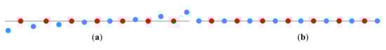
Figure 4.
The APCF in a dual-channel sliding spotlight SAR-GMTI system, () before, and () after the channel phase mismatch calibration. The red points represent the first antenna (the reference channel) phase centers and the blue points represent the second antenna phase centers.
2.2. Spatial Channel Co-Registration after Phase Mismatch Calibration
Implementation of spatial channel co-registration requires accurate azimuth time difference between the two channels, which is the essential step of the DPCA method. After the phase mismatch calibration, the antenna phase centers are aligned with the sensor path, and the azimuth time difference between the two channels can be estimated. For the dual-channel stripmap SAR systems, the azimuth time difference between the two channels is . Nevertheless, we find that the azimuth time difference becomes after the phase mismatch calibration during the sliding spotlight SAR data processing, where A is the hybrid factor of a sliding spotlight SAR. It is defined as
where is the scanning velocity of the beam on the ground, and represents the closest slant range from the SAR sensor to the virtual rotation center, which can be found in Figure 3a.
We will further analyze the issue of the azimuth time difference between channels in this section since it determines the accuracy of spatial channel co-registration and clutter cancellation. The scanning angle of actual spaceborne SAR systems operated in sliding spotlight mode is small. For example, the maximum scanning angles of TerraSAR-X and Gaofen-3 are 0.75° and 1.9° [15,19]. Therefore, using the small angle approximation and the imaging geometry of sliding spotlight mode in Figure 3a, the phase mismatch in Equation (3) can be further approximated as
It can be seen from Equation (8) that the phase mismatch varies linearly with respect to the azimuth time . Therefore, not only the channel phase mismatch is calibrated, but there is also a spectrum shifting in azimuth according to the Fourier transform properties. As a result, the estimated time difference between two channels is instead of . In the following, a derivation that utilizes scattering point model is provided to quantify the variation of azimuth time difference accurately. Since the range signal does not affect the azimuth after range cell migration correction, it can be simply assumed that the azimuth signals of two channels are expressed as
where and represent the antenna’s two-way power pattern. In addition, the actual scanning angle range of Gaofen-3 operated in sliding spotlight mode is −1.35∼1.35 during this experiment. The antenna beam steering is carried out on a burst basis [20]. The stepped scanning angle is , and the number of pulse at one scanning angle is 121. There is only a slight difference between Equations (3) and the approximation in Equation (8), which is illustrated in Figure 5.
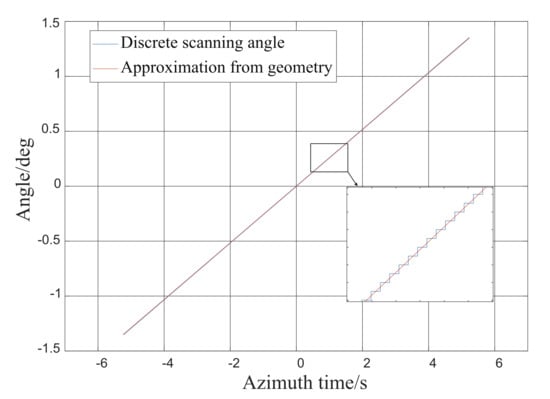
Figure 5.
Difference between the actual discrete scanning angle of the Gaofen-3 system that operated in sliding spotlight mode during this experiment and the approximate result in Equation (8).
Accordingly, substituting Equation (8) into Equation (9) to perform the phase mismatch calibration on the second channel yields , which is described as
Moreover, the relationship between and can be expressed as
After the azimuth Fourier transform, the relationship between the signals from two channels in the azimuth-frequency domain can be described as
where represents the azimuth frequency and represents the azimuth frequency rate. Then, the cross-correlation coefficient between the two signals after the phase mismatch calibration can be obtained as
From Equation (13), the azimuth time difference between the two channels of sliding spotlight SAR after the phase mismatch calibration is . Therefore, the two channels can be co-registered spatially by a constant time shift in azimuth, and clutter can be suppressed by the channel cancellation. The complete signal processing flowchart based on the DPCA method with the proposed phase mismatch calibration is shown in Figure 6. First, the inevitable channel imbalance, such as amplitude imbalance, range sampling time error, and phase mismatches from other origins, must be calibrated [18,21] before the implementation of channel cancellation. The second step is to obtain and compensate the channel phase mismatch based on Equation (3). The azimuth time difference between the two channels can be estimated, and the spatial channel co-registration is implemented accordingly later. Finally, the clutter suppression can be obtained by the cancellation of two SAR images, and the moving targets can be detected by the two-dimensional cell-averaging constant false alarm rate (CFAR) detector [22]. The pseudocode of the processing scheme is presented in Algorithm 1.
| Algorithm 1 DPCA algorithm with proposed phase mismatch calibration |
| Input: The raw two-channel dataset of sliding spotlight SAR ,, The SAR system parameters; Output: The moving target detection result R by CFAR;
|
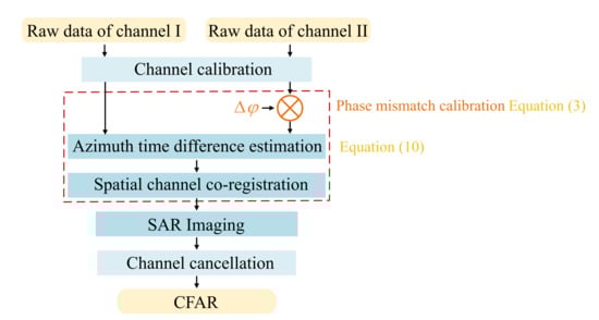
Figure 6.
Complete signal processing flowchart of the DPCA method based on the proposed phase mismatch calibration for dual-channel sliding spotlight SAR-GMTI systems.
3. Experimental Results and Analysis
This section verifies the correctness of our conclusions, including the phase mismatch calibration and azimuth time difference variation. The dual-channel sliding spotlight SAR data that collected from an experiment by the spaceborne Gaofen-3 system in June 2021 is used to demonstrate the validation of the proposed phase mismatch calibration for GMTI. The location selected for this experiment is Des Moines, Iowa, United States, which includes some moving targets on the roads and railways. The main parameters of this system are tabulated in Table 1. The entire phased array antenna length of the Gaofen-3 system is 15 m. In the dual-channel sliding spotlight mode, only half the azimuth size is used for transmitting and receiving signals, and the actual receiving antenna spacing is 3.75 m.

Table 1.
Main parameters of the Gaofen-3 system operated in sliding spotlight mode.
3.1. Antenna Spacing Estimation
The implementation of the spatial channel co-registration in the DPCA method requires the accurate estimation of azimuth time difference between the two channels and receiving antenna spacing. Figure 7a illustrates the interferometric phase of the Des Moines scene before the phase mismatch calibration in the Doppler domain, i.e., the phase
where represents the range time, and represents the azimuth frequency. The slowly varying linear phase along the azimuth frequency (Doppler) can be expressed as
where represents the azimuth time difference of the two receiving antennas. It can be seen from Figure 7a that the varying linear phase along the azimuth frequency is unclear. Figure 7c shows that the interferometric phase of the Des Moines scene after the proposed phase mismatch calibration, and the linear phase can easily be recognized. Then, the antenna spacing D can be obtained by the slope of the interferometric phase line, which can be expressed as
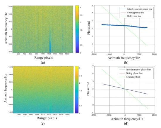
Figure 7.
Antenna spacing estimation results of the Gaofen-3 system operated in sliding spotlight mode by the slope of the slowly varying linear phase along the azimuth frequency. () The interferometric phase of the Des Moines scene before the phase mismatch calibration in the Doppler domain, () the slowly varying linear phase along the azimuth frequency before the proposed phase mismatch calibration, () the interferometric phase of the Des Moines scene after the phase mismatch calibration, () the varying linear phase after the calibration.
Figure 7b shows the antenna spacing estimation result before the phase mismatch calibration. The slope of the linear phase along the azimuth frequency, which is obtained by a least-squares fit, is a variable value as discussed in Section 2. The slope of the reference line (green) corresponds to the actual antenna spacing of the Gaofen-3, which is 3.75 meters. The hybrid factor of Gaofen-3 system in this experiment is
Based on Equation (16), the theoretical value of antenna spacing estimation result after the proposed phase mismatch calibration is , which is meters. Figure 7d shows the linear phase along the azimuth frequency after the phase mismatch calibration, and the estimated antenna spacing obtained by the slope the fitting phase line is 1.11 m. The estimated value of the antenna spacing is consistent with the theoretical value . Thus, the azimuth time difference between the two channels in sliding spotlight SAR after the phase mismatch calibration is related to the actual antenna spacing and the hybrid factor. There is a slight error between the theoretical value and the estimated result, which can be be attributed to two aspects, the approximation used in Equation (8) and the discrete scanning angle of the Gaofen-3 system.
3.2. Ground Moving Target Indication
The clutter suppression results and performance analyses are presented in this subsection. After the proposed phase mismatch calibration and the azimuth time shift, the two channels are spatially co-registered, which is illustrated in Figure 8. The interferometric phase of the Des Moines scene shows that the slowly varying linear phase along the azimuth frequency is removed, and the slope of the interferometric phase line along Doppler is 0, which indicates that the images from two channels are ready for cancellation.
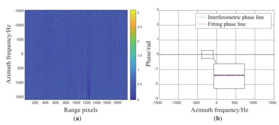
Figure 8.
() The interferometric phase of the Des Moines scene versus the azimuth frequency after the spatial channel co-registration, () the interferometric phase line along the azimuth frequency after the spatial channel co-registration.
Figure 9a shows the whole area of interest obtained by the Gaofen-3 system operated in sliding spotlight mode in this experiment. The clutter suppression result of the conventional DPCA method is shown in Figure 9b. It can be seen that only a small area of clutter in the middle is suppressed partially, but most of the clutter on both sides is strengthened instead. The power of the clutter on both sides is strengthened by about 2.5095 dB, which indicates the failure of the channel cancellation. A probable explanation for the clutter suppression of the middle area is that the squint angle of the sliding spotlight SAR system corresponding to the data in middle area is very close to zero, and the burst basis of the antenna beam steering [20]. Hence, the middle area data of the two channels have little mismatch relates to the beam sweeping, which is similar to the stripmap SAR data. Then, the clutter in this area can be suppressed by the DPCA method.
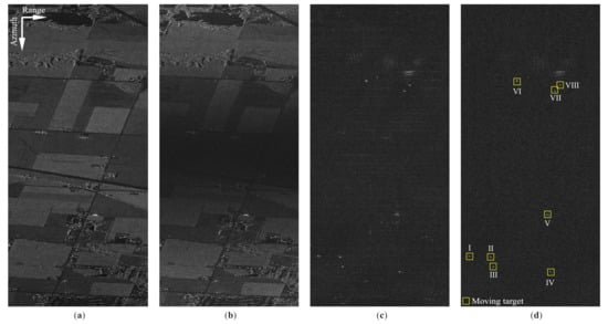
Figure 9.
Imaging result of acquired one-channel-SAR data by the experiment and clutter suppression results: () the focused SAR image, () the clutter suppression result by the conventional DPCA method, () the clutter suppression result by the DPCA with 2D-DB, () the clutter suppression result by the DPCA method with the proposed phase mismatch calibration, and the detected moving targets marked by yellow boxes.
Figure 9c shows the clutter suppression result by the DPCA with blocked 2D-digital balancing (DB), which was proposed in [8]. The clutter power reduction is about 7.2743 dB. Moreover, it is obvious that there is some clutter at the junction of each data block that is not well suppressed. Figure 9d shows the clutter suppression result obtained by the DPCA method with the proposed phase mismatch calibration, which utilizes Equation (3) with the discrete scanning angle of the Gaofen-3 system. It is noted that the power of clutter can be reduced by about 8.5338 dB. Moreover, the proposed method has a better performance in clutter suppression with no clutter residue at the data where the scanning angle is switched. Then, moving targets can be detected by the CFAR detector, and they are marked by the yellow rectangles in Figure 9c.
Figure 10 compares the power of the range cells, where the detected moving targets in Figure 9c are located before and after clutter suppression by the DPCA with proposed phase mismatch calibration. The blue lines denote the signals before clutter suppression and the red lines denote the signals after clutter suppression. Moreover, Table 2 shows the input and output signal-to-clutter ratios (SCRs) and improvement factors (IFs) of the detected moving targets. According to the power reduction of clutter, the power of the detected moving targets are enhanced by the channel cancellation, except for target IV, which may be attributed to its low radial velocity. To sum up, the DPCA with the proposed phase mismatch calibration can effectively suppress clutter in the dual-channel sliding spotlight SAR-GMTI.
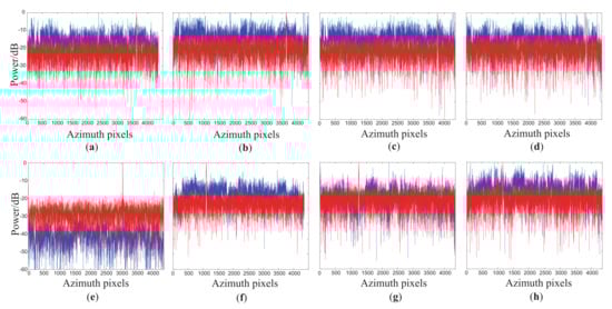
Figure 10.
Power comparisons of the detected moving targets before and after clutter suppression. (a–h) show the power variations of the range cells where the detected moving targets (I∼VIII) marked in Figure 9c are located. The blue line and the red line represent the signals before and after clutter suppression, respectively.
Table 2.
SCRs and IFs of the detected moving targets before and after the clutter cancellation.
Moreover, since most of the steps of the proposed clutter suppression method are the Hadamard product and subtraction of the signal matrices, the computational load is relatively low. The image size is 4096 × 2048 pixels, and the experiment was manipulated by MATLAB 2021 with the computer that was configured with i7-10750H CPU, six cores, twelve threads, and 32-GB RAM. With the same experiment, the computational times of the DPCA with blocked 2D-DB and the proposed method is tabulated in Table 3, indicating that the proposed method has a high computational efficiency, which is very close to the conventional DPCA method.
Table 3.
Comparison of computational times of clutter suppression methods.
4. Conclusions
This paper addresses the issue of phase mismatch caused by the beam steering on the processing of dual-channel sliding spotlight SAR data for GMTI. Different from the stripmap SAR, the phase caused by beam progressive sweeping in azimuth causes the antenna phase centers to be misaligned from the sensor path. Consequently, the two channels cannot be spatially co-registered, resulting in the failure of channel cancellation. In this work, the APCF-induced phase mismatch is obtained quantitatively based on the imaging geometry of sliding spotlight mode, and the antenna phase centers are proved to be re-aligned after the phase calibration. Moreover, the effect of the calibration on the azimuth time difference estimation is deeply analyzed and derived for accurate implementation of the spatial channel co-registration in the DPCA. Finally, we carried out an experiment with the Gaofen-3 system operated in sliding spotlight mode to acquire the actual data. The processing results of clutter suppression with the experimental data have validated the effectiveness of the proposed phase mismatch calibration.
In addition, the calibration method provides a useful reference for the dual-channel spotlight SAR data processing due to the similar scanning geometry of both modes. The investigation for spotlight SAR-GMTI and parameter estimation based on coordinated experiments will be performed in the near future.
Author Contributions
Conceptualization of the Manuscript Idea: Z.Z., M.Z. and Z.-X.Z.; Methodology and Software: Z.Z., M.Z. and L.Z.; Supervision and Funding Acquisition: W.Y.; Wrote the original draft preparation: Z.Z.; Reviewed and edited this paper: W.Y. and Z.-X.Z. All authors have read and agreed to the published version of the manuscript.
Funding
This work was funded by the Civil Space Pre-Research Project D04114.
Data Availability Statement
Not applicable.
Conflicts of Interest
The authors declare no conflict of interest.
References
- Xu, W.; Huang, P.; Wang, R.; Deng, Y. Processing of Multichannel Sliding Spotlight and TOPS Synthetic Aperture Radar Data. IEEE Trans. Geosci. Remote Sens. 2013, 51, 4417–4429. [Google Scholar] [CrossRef]
- De Zan, F.; Monti Guarnieri, A. TOPSAR: Terrain Observation by Progressive Scans. IEEE Trans. Geosci. Remote Sens. 2006, 44, 2352–2360. [Google Scholar] [CrossRef]
- Quegan, S. Spotlight Synthetic Aperture Radar: Signal Processing Algorithms. J. Atmos. Sol.-Terr. Phys. 1995, 59, 597–598. [Google Scholar] [CrossRef]
- Mittermayer, J.; Lord, R.; Borner, E. Sliding spotlight SAR processing for TerraSAR-X using a new formulation of the extended chirp scaling algorithm. In Proceedings of the 2003 IEEE International Geoscience and Remote Sensing Symposium, Toulouse, France, 21–25 July 2003; Volume 3, pp. 1462–1464. [Google Scholar]
- Prats, P.; Scheiber, R.; Mittermayer, J.; Meta, A.; Moreira, A. Processing of Sliding Spotlight and TOPS SAR Data Using Baseband Azimuth Scaling. IEEE Trans. Geosci. Remote Sens. 2010, 48, 770–780. [Google Scholar] [CrossRef] [Green Version]
- Sun, G.C.; Xing, M.; Xia, X.G.; Wu, Y.; Huang, P.; Wu, Y.; Bao, Z. Multichannel Full-Aperture Azimuth Processing for Beam Steering SAR. IEEE Trans. Geosci. Remote Sens. 2013, 51, 4761–4778. [Google Scholar] [CrossRef]
- Yang, J.; Qiu, X.; Zhong, L.; Shang, M.; Ding, C. A Simultaneous Imaging Scheme of Stationary Clutter and Moving Targets for Maritime Scenarios with the First Chinese Dual-Channel Spaceborne SAR Sensor. Remote Sens. 2019, 11, 2275. [Google Scholar] [CrossRef] [Green Version]
- Shen, W.; Hong, W.; Han, B.; Zhao, L.; Lin, Y.; Wang, Y.; Zhang, Q.; Yu, W.; Bi, H. First Result of Spaceborne Dual-Channel Spotlight SAR GMTI Experiment Using Chinese Gaofen-3 Satelite. In Proceedings of the EUSAR 2021: 13th European Conference on Synthetic Aperture Radar, Online Event, 29 March–1 April 2021; pp. 1–5. [Google Scholar]
- Sjoegren, T.; Vu, V.; Mats, P. Experimental result for SAR GMTI using monostatic pursuit mode of TerraSAR-X and TanDEM-X on Staring Spotlight images. In Proceedings of the EUSAR 2016: 11th European Conference on Synthetic Aperture Radar, Hamburg, Germany, 6–9 June 2016; pp. 1–4. [Google Scholar]
- Pastina, D.; Buratta, L.; Turin, F.; Cristallini, D. Exploiting COSMO-SkyMed spotlight SAR images for GMTI applications. In Proceedings of the 2011 IEEE CIE International Conference on Radar, Chengdu, China, 24–27 October 2011; Volume 2, pp. 1918–1921. [Google Scholar]
- Lightstone, L.; Faubert, D.; Rempel, G. Multiple phase centre DPCA for airborne radar. In Proceedings of the 1991 IEEE National Radar Conference, Los Angeles, CA, USA, 12–13 March 1991; pp. 36–40. [Google Scholar]
- Kim, S.W.; Won, J.S. Acceleration Compensation for Estimation of Along-Track Velocity of Ground Moving Target from Single-Channel SAR SLC Data. Remote Sens. 2020, 12, 1609. [Google Scholar] [CrossRef]
- Dudczyk, J.; Kawalec, A. Optimizing the minimum cost flow algorithm for the phase unwrapping process in SAR radar. Bull. Pol. Acad. Sci. 2014, 62, 511–516. [Google Scholar] [CrossRef] [Green Version]
- Fan, H.; Zhang, Z.; Wang, R.; Zhang, H.; Wang, X.; Li, N. Robust phase mismatch calibration for Multichannel Sliding Spotlight SAR Imaging. Remote Sens. Lett. 2017, 8, 869–878. [Google Scholar] [CrossRef]
- Fan, H.; Zhang, L.; Zhang, Z.; Yu, W.; Deng, Y. On the Processing of Gaofen-3 Spaceborne Dual-Channel Sliding Spotlight SAR Data. IEEE Trans. Geosci. Remote Sens. 2022, 60, 1–12. [Google Scholar] [CrossRef]
- Madsen, S. Estimating the Doppler centroid of SAR data. IEEE Trans. Aerosp. Electron. Syst. 1989, 25, 134–140. [Google Scholar] [CrossRef] [Green Version]
- Zhang, Z.; Yu, W.; Zheng, M.; Zhou, Z.X. Doppler Centroid Estimation for Ground Moving Target in Multichannel HRWS SAR System. IEEE Geosci. Remote Sens. Lett. 2022, 19, 1–5. [Google Scholar] [CrossRef]
- Feng, J.; Gao, C.; Zhang, Y.; Wang, R. Phase Mismatch Calibration of the Multichannel SAR Based on Azimuth Cross Correlation. IEEE Geosci. Remote Sens. Lett. 2013, 10, 903–907. [Google Scholar] [CrossRef]
- Eineder, M.; Adam, N.; Bamler, R.; Yague-Martinez, N.; Breit, H. Spaceborne Spotlight SAR Interferometry with TerraSAR-X. IEEE Trans. Geosci. Remote Sens. 2009, 47, 1524–1535. [Google Scholar] [CrossRef]
- Zamparelli, V.; Agram, P.S.; Fornaro, G. Estimation and Compensation of Phase Shifts in SAR Focusing of Spotlight Data Acquired With Discrete Antenna Steering. IEEE Geosci. Remote Sens. Lett. 2014, 11, 1921–1925. [Google Scholar] [CrossRef]
- Shang, M.; Qiu, X.; Han, B.; Ding, C.; Hu, Y. Channel Imbalances and Along-Track Baseline Estimation for the GF-3 Azimuth Multichannel Mode. Remote Sens. 2019, 11, 1297. [Google Scholar] [CrossRef] [Green Version]
- Lombardo, P.; Sciotti, M.; Kaplan, L.M. SAR prescreening using both target and shadow information. In Proceedings of the 2001 IEEE Radar Conference, Atlanta, GA, USA, 3 May 2001; pp. 147–152. [Google Scholar]
Publisher’s Note: MDPI stays neutral with regard to jurisdictional claims in published maps and institutional affiliations. |
© 2022 by the authors. Licensee MDPI, Basel, Switzerland. This article is an open access article distributed under the terms and conditions of the Creative Commons Attribution (CC BY) license (https://creativecommons.org/licenses/by/4.0/).