Abstract
The accuracy of time synchronization can be significantly increased by enhancing the performance of atomic clocks. Future-generation time-frequency loads will be equipped with the latest ultrahigh-precision atomic clocks (with a day stability better than 10−17) and will leverage advantages of the space environment such as microgravity and low interference to operate a new generation of high-performance time-frequency payloads on low-orbit spacecraft. Moreover, using the high-precision time-frequency system of ground stations, low-time-delay high-performance time-frequency transmission networks, which have the potential to achieve ultrahigh-precision time synchronization, will be constructed. By considering full link error terms above the picosecond level, this paper proposes a new space-to-ground microwave two-way time synchronization method for scenarios involving low-orbit spacecraft and ground stations. Using the theoretical principles and practical application scenarios related to this method, a theoretical and simulation verification platform was developed to research the impact of the attitude, phase center calibration, and orbit determination errors on the single-frequency two-way time synchronization method. The effectiveness of this new method was verified. The results showed that when the attitude error is less than 72 arc seconds (0.02°), the phase center calibration error is less than 1 mm, and the precision orbit determination (POD) error is less than 10 cm (three-axis). After disregarding nonlink error terms such as equipment noise, this method can attain a space-to-ground time synchronization accuracy of better than 1.5 ps, and the time deviation (TDEV) of the transfer link is better than 0.7 ps @ 100 s, which results in ultrahigh-precision space-to-ground time synchronization.
1. Introduction
At present, optical fiber link time comparison technology [1], which can achieve the highest picosecond time synchronization accuracy, is the most accurate of the commonly used long-distance time transfer methods. However, broad applications of this technology have been problematic due to limitations of the atmospheric environment. Moreover, the microwave satellite-to-ground/intersatellite two-way time comparison system, which is widely used in navigation systems, is limited by the performance of spaceborne atomic clocks and the error processing method of the comparison link. This system can only achieve sub-nanosecond time synchronization accuracy [2], which limits the application of high-precision time-frequency references in space science.
The time-frequency performance of space atomic clocks will be better [3,4] than that of terrestrial atomic clocks in a near-Earth microgravity environment, thus enabling a time system with ultrahigh stability to be constructed. Using the low-orbit spacecraft-ground station high-performance microwave two-way time comparison link, ultrahigh-precision two-way time synchronization can be achieved between the ground and space.
In recent years, with the rapid development of space atomic clock technology, long-distance transmission technology for high-precision time and frequency transfer has become a research topic of major interest [5]. High-precision time and frequency transfer can be widely used in applications such as basic physical testing, geophysical measurements, relativity verifications, satellite navigation, and deep space exploration and is an effective means for evaluating the performance of high-precision atomic clocks in space [6].
The ACES/PHARAO (Atomic Clock Ensemble in Space, ACES) is an international metrological space mission [7,8] led by the European Space Agency (ESA) and the French Space Agency (Centre National d’Études Spatiales, CNES). The aim of this mission is to use the cesium cold atom clock (PHARAO) and the space hydrogen maser atomic clock (SHM), jointly developed by the CNES and LNE-SYRTE, to achieve high-stability and high-precision time and frequency standards on the International Space Station (ISS), reaching the long-term frequency stability of @ 1 day and time stability of 12 ps @ 1 day. The mission further strives to establish a high-precision microwave time-frequency transmission system [9] (Microwave Link, MWL) and a laser time-frequency transmission system [10] (European Laser Timing, ELT) with an ultrastable ground-based clock. In addition, by using a corresponding precision time synchronization algorithm, a space-to-ground link stability of better than 7 ps @ 1 day and 0.3 ps @ 300 s can be achieved [11]. To improve the accuracy of space-to-ground time-frequency transmissions, ESA has further attempted to conduct the proposed EGE (Einstein Gravity Explorer, EGE), I-SOC (Space Optical Clock on ISS, I-SOC), and Kepler projects [12,13,14], with the purpose of further improving the accuracy of the space atomic clock based on the ESA-ACES project, thereby achieving ultrahigh-precision space-to-ground time synchronization [15], while carrying out a series of basic physical verification tests and significantly improving the time-frequency performance of the constellation.
China has also been stepping up its deployment and construction of high-precision time-frequency systems for the China Space Station (CSS), equipping them with high-precision new-generation space atomic clocks to establish ultrahigh-precision time-frequency sources [16], to achieve high-precision time synchronization, and to support the exploration of cutting-edge scientific issues such as gravitational redshifts and precision structures.
In the space atomic clock projects, the realization of ultrahigh-precision time comparison has become an urgent requirement for the evaluation of atomic clocks, scientific research, and the expansion of applications. The traditional two-way time synchronization method can no longer meet the demand for high-precision time and frequency transmission [17]; therefore, a new microwave link time synchronization method is needed to achieve ultrahigh-precision space-to-ground time synchronization.
Using the synchronization application scenario of a low-orbit spacecraft equipped with a new generation of high-performance atomic clocks and ground stations, this paper proposes a new method of space-to-ground microwave time synchronization based on the characteristics of a low-orbit spacecraft’s fast near-Earth flight speed and uncertain orbital parameters [18]. A software simulation analysis platform was also developed based on actual application scenarios. Key technology related to the high-precision time synchronization of space-to-ground links, which can achieve a space-to-ground time synchronization accuracy of 1.5 ps, was verified through simulation tests. Consequently, these developments provide a theoretical basis and technical reference for the construction of China’s manned spaceflights and other projects.
2. A New Method for Space-to-Ground Two-Way Time Synchronization
2.1. New Generation of Space Time-Frequency Loads
The integration of next-generation high-performance atomic clocks and related equipment is referred to as a new generation of space time-frequency payloads. Ultrahigh-precision space-to-ground time synchronization is based on high-precision atomic clocks installed in space and on the ground that use the near-Earth orbit of a low-orbit spacecraft (orbital height of approximately 400 km and orbital inclination of approximately 42°) to operate a new generation of space atomic clocks that can obtain a time-frequency reference that is several orders of magnitude higher than that of the ground and achieve high-precision space-to-ground time synchronization through high-performance space-to-ground microwave links. The new generation of space time-frequency loads may include the following components [19,20]:
- High-performance space atomic clock (Allan deviation better than 10−17 @ 1 day);
- Precise orbit determination of Global Navigation Satellite System (GNSS) receivers;
- Microwave link module for code and carrier phase measurements;
- Laser link module.
In future scientific missions, the demand for time accuracy will increase. Therefore, the installation of a new generation of time-frequency payloads on spacecraft and the use of microwave links to achieve long-distance and ultrahigh-precision time transfer between targets promise to become research topics of major interest [21,22]. China has also proposed establishing a high-precision time-frequency generating and operating system (space-precision time-frequency reference) in space and has constructed a high-precision time-frequency network based on microwave links to meet the high-precision time requirements of various spacecraft and users. To achieve this goal, a stable and reliable time synchronization method needs to be redesigned to support the realization of ultrahigh-precision time synchronization.
2.2. Space-to-Ground Two-Way Time Synchronization Principle Based on a Single Frequency Mode
The new generation of space time-frequency loads envisions a dual-antenna structure. The two-way ranging signal adopts a signal transceiver mode with a single frequency point and different antennas employing simultaneous sending or receiving. Figure 1 shows a schematic diagram of the transceiver antenna installation for the precise orbit determination module and the microwave link module carried on the time-frequency load in this mode. The GNSS receiver antenna used to determine the orbit will be installed in space and use an intersatellite link with the GNSS satellites being used to achieve precision. The center point of the antenna installation surface is A3; the center point of the signal-receiving antenna installation surface of the microwave link module is A1, and the center point of the signal-transmitting antenna installation surface is A2. To avoid signal interference, the transmitting and receiving antennas need to be separated. As a result, there is a fixed safe distance (a few centimeters) between A1 and A2, and the antennas are installed relative to the ground to achieve high-precision time synchronization with ground equipment; A is the center of mass of the spacecraft. As the GNSS receiver antenna and the microwave link module antenna are connected by a rigid body, the coordinate conversion relationship between A, A1, A2, and A3 can be obtained through calibration on the ground beforehand (see the red line in Figure 1). Coordinates of the other three positions can then be calculated based on any one of these coordinates.

Figure 1.
Schematic diagram of the antenna installation.
Therefore, the coordinate conversion relationship between the center point of the installation surface of the low-orbit spacecraft microwave link module transmitting antenna, the center point of the receiving antenna installation surface of the low-orbit spacecraft microwave link module, and the center of mass of the low-orbit spacecraft is as follows:
where and represent the coordinate conversion matrix, which can be obtained through calibration.
Based on the new-generation space load and single-frequency dual-antenna signal transceiver system, the space-to-ground two-way time synchronization and the Ka intersatellite link two-way time synchronization of the Beidou satellite navigation system both adopt a single-frequency dual one-way measurement mode. The difference between the two-way pseudorange can eliminate most of the geometric path delay errors. The time synchronization accuracy is high, which is an effective means for long-distance time transmission. In contrast to the two-way time synchronization of the Beidou satellite navigation system’s Ka intersatellite link, the signal transmission and reception system of the Ka satellite-to-ground two-way time synchronization system uses a time division multiple access (TDMA) mode [23]. However, the low-orbit spacecraft will adopt a continuous and simultaneous transmission and reception mode due to the limited number of visible arcs with the ground and the short duration. In addition, the low-orbit spacecraft will be equipped with the latest generation of ultrahigh-precision atomic clocks, which can achieve higher-precision time synchronization through high-performance microwave time comparison links and time synchronization algorithms.
Both the low-orbit spacecraft atomic clock and the ground station clock fall in the Earth’s gravitational field. To achieve picosecond time synchronization accuracy, the influence of the Earth’s gravity must be fully considered. The expected time synchronization accuracy can ultimately be achieved by establishing a two-way measurement model on this basis [24]. Assuming that the low-orbit spacecraft and the ground station receive signals with frequency (Ka band, 20–30 GHz) at the same moment (see red double arrows in Figure 2), the principle of space-to-ground two-way time synchronization is shown in Figure 2. In the Earth-centered inertial (ECI) coordinate system, the measurement equation for establishing a dual one-way measurement between the low-Earth-orbit (LEO) spacecraft and the ground station is
where is the speed of light in vacuum, A is a low-orbit spacecraft, B is a ground station, and are the signal transmission and reception times, respectively, and are the uplink and downlink measurement pseudoranges of the frequency point, respectively, and is the trajectory coordinate matrix of center point of the installation surface of the spacecraft time-frequency signal-receiving antenna. is the trajectory coordinate matrix of center point of the low-orbit spacecraft time-frequency signal-transmitting antenna installation surface, and is the coordinate matrix of the ground station, while and are the clock differences between the atomic clock of the low-orbit spacecraft and the atomic clock of the ground station, respectively. Furthermore, and are the equipment delays of the signal transmission channel and the receiving channel, respectively, is the equivalent time delay of the periodic relativistic effect, is the equivalent time delay of the phase center shift, is the gravitational time delay, and is the ranging noise.
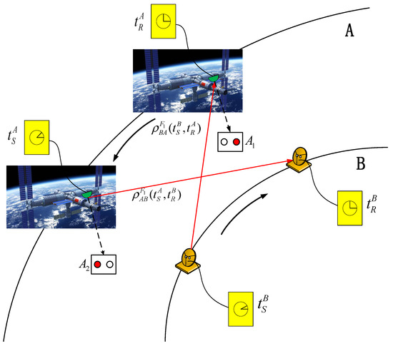
Figure 2.
Principle of space-to-ground microwave two-way (red double arrows) time synchronization.
According to the conversion relationship of Formula (1), Formula (2) can be modified as follows:
Due to the space transmission delay of the signal and the ultrahigh-speed movement of the low-orbit spacecraft, the space-to-ground two-way pseudorange measurement value contains the low-orbit spacecraft position and the clock difference information at different times. For the two-way ranging for the same receiving time , Equation (3) can be modified as
In this formula, is the correction of the space distance error caused by the motion of the low-orbit spacecraft, is the nonsimultaneous correction of the clock difference from time to time , and and represent the nonsimultaneous error corrections to the clock difference between ground station B and low-orbit spacecraft A, respectively.
In the single-frequency mode, the frequencies of the uplink and downlink ranging signals between the LEO spacecraft and the ground station are the same, and the paths are nearly identical. Therefore, ionospheric and tropospheric delays can be ignored in the two-way time difference measurements. After the system error correction is completed, the difference between the two equations in (4) can be calculated to obtain the relative clock error between the space and the ground as follows:
Based on Equation (5), the accuracy of space-to-ground time synchronization largely depends on the difference between various delays. Therefore, when the conditions for achieving a higher transmission accuracy are met, in addition to considering the aforementioned data processing method under the same frequency signal system, a more accurate error processing method is also required.
2.3. Various Error Corrections of High-Precision Space-to-Ground Time Synchronization
In the context of high-precision (10−17@ 1 day) atomic clocks mounted on high-speed low-orbit spacecraft, precision adjustments must be performed on every error-generated term during the space-to-ground two-way time synchronization process to achieve higher-precision time transmission requirements. In Equation (5), the equipment time delay can be accurately calibrated in orbit [25]; the phase center error can be compensated for by performing an accurate calibration along with the corresponding modeling in advance [26]; space-to-ground link measurement noise appears as a random error, for which filtering operations must be conducted based on the statistical properties of the error. Therefore, based on the link accuracy requirements of ultrahigh-precision time synchronization, the main error correction terms considered for space-to-ground two-way time synchronization in single-frequency mode include error corrections for motion delay, periodic relativistic effects, and gravitational delay.
2.3.1. Motion Delay Error Correction
The motion delay error caused by the high-speed motion of the low-orbit spacecraft relative to the ground station in space involves two main errors: the space distance error (asymmetric spatial geometric distance) and the clock difference error (nonsimultaneous difference in clocks).
According to Equations (3)–(5), the precision orbit determination (POD) and precision clock difference results of the low-orbit spacecraft can be used to time-scale the pseudorange of the same-frequency dual single-way observation at different times and different antenna positions and to perform time-scale reduction and motion delay error correction [27]. The motion delay error correction amount is expressed as follows:
The space distance error correction amount and the clock error correction amount can be expressed as follows:
and
where is the uplink measurement pseudorange of the signal, and is the downlink measurement pseudorange of the signal. The coordinate track of the ground station in the ECI coordinate system is already known, and is the result of the POD of a low-orbit spacecraft. and are the clock differences between the LEO spacecraft and the ground station, respectively.
2.3.2. Correction of Periodic Relativistic Error Effect
The relativistic effects of spaceborne atomic clocks include nominal frequency offsets (NFOs) and periodic relativistic effects [28]. The NFO can be eliminated through precalibration before the spacecraft is launched, and the periodic relativistic effects can be eliminated by modeling. Due to the periodic relativistic effects in the space-to-ground two-way time comparisons, there is no path symmetry, and the ephemeris must be used for compensation. Thus, the compensation error will eventually be directly transmitted to the time comparison result. Due to its low orbit, the spacecraft is greatly affected by the nonspherical gravity of the Earth. When considering the time synchronization accuracy of a picosecond or higher, the influence of the periodic relativistic errors of the first term and higher-order terms from the nonspherical gravity of the Earth must be fully considered [29]. The periodic relativistic correction in the two-way time synchronization process between the low-orbit spacecraft and the ground station is expressed as follows:
The expression of the periodic relativistic error when considering the perturbation of the term is as follows:
where is the gravitational constant of Earth, is the equatorial radius of Earth, and , , , , and are the corresponding times for the orbital inclination angle, semimajor axis of the orbital period, orbital eccentricity, latitude argument, and eccentric anomaly of the low-orbit spacecraft, respectively. The disturbance error of the higher-order terms is represented by .
2.3.3. Gravitational Time Delay Error Correction
Space-to-ground two-way time synchronization is based on the mutual transmission of ranging signals between low-orbit spacecraft and ground stations. As the signal transmission process is affected by general relativistic effects, there is a gravitational time delay. The gravitational delay in the space propagation process of the space-to-ground ranging signal mainly depends on the relative position of the ground station and the low-orbit spacecraft to the center relative to Earth, and the gravitational time delay in the two-way space-to-ground time synchronization process can be calculated by using the results of precise orbit determination conducted afterward. With a picosecond time transfer accuracy, only the gravitational delay caused by the gravity of the center of Earth needs to be considered [30]. At this point, the gravitational delay correction is as follows:
where the expression for the signal propagation path AB (A and B correspond to the antenna phase center between the two targets) is as follows, considering only the gravitational time delay error caused by gravity at the center of Earth:
In this formula, . Moreover, and are the geocentric distances when the low-orbit spacecraft and ground station receive and send ranging signals.
3. Simulation Test and Performance Analysis
To effectively verify the feasibility of the space-to-ground two-way time synchronization method under high-performance requirements, a simulation and verification platform was established, and the architecture is shown in Figure 3. It contains two parts, the simulation module and verification module.
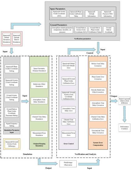
Figure 3.
Platform architecture of the space-to-ground time synchronization simulation verification.
First, we simulated the satellite orbit data and attitude data based on the specific satellite orbit parameters, attitude model, and the Earth model (Earth Gravity Model, N-body Gravity Model, Tidal Model, etc.). Further, we used the orbit data and attitude data to obtain the part of simulation parameters and verification parameters (gray box in Figure 3). Then, the real movement and disturbance of the Earth, satellite equipment, and ground equipment were considered, and simulation parameters, clock models (yellow box in Figure 3), and error models (green box in Figure 3) were set to restore the true process of time signal propagation and generate pseudorange observation data.
To validate, the pseudorange observations and verification parameters generated by the simulation module were used as the input of the verification module. Similar to the process of two-way ranging data of the BDS-3 Ka-band satellite-ground links (GSLs), some main system errors (orange box in Figure 3) need to be corrected, including the orbit-related errors (motion delay error, relativistic error, and gravitational time delay error) [31]. After correcting these main system errors, the space-to-ground two-way time synchronization algorithm proposed in Section 2 was executed, and the result of the space-to-ground relative clock difference can be obtained; then, related analyses can be carried out by controlling different error inputs (purple box in Figure 3).
3.1. Low-Orbit Spacecraft-to-Ground Station Simulation Experiment
Based on the above simulation verification platform, the low-orbit spacecraft was set to run in a low-Earth orbit with an orbital height of 400 km and an orbital inclination of 42°. The other parameter settings were roughly the same as those of Tiangong-2 [32], assuming that the location of the ground station was in Xi’an. Using the atomic clock of the ground station as a reference benchmark, the simulation generated the atomic clock difference between the ground station and the low-orbit spacecraft. The day stability of the atomic clock at the Xi’an Ground Station was set at E-18, and the day stability of the low-orbit spacecraft was set at 10−17.
Ignoring the equipment delay and other measurement errors caused by the equipment, the off-axis angle of the ground station antenna was set to 66°, the center points of the low-orbit spacecraft transceiver antenna installation surface were 10 cm apart, and the antenna off-axis angle was 15–89°. The space-to-ground time comparison simulation platform generated a one-day (1 January 2020) dual one-way pseudorange observed measurement (sampling rate: 1 Hz) between the low-orbit spacecraft and the ground station, and a total of five continuous arcs of observation data were obtained (Table 1). The dual one-way observations included various delay components such as the geometric distance, the motion time delay (distance error and clock difference error), the atmospheric time delay, and the relativistic time delay [33].

Table 1.
Observations of the low-orbit spacecraft-ground station chain construction on 1 January 2020.
Figure 4a shows the uplink and downlink observation data of the first continuous observation arc (approximately 380 s), and Figure 4b shows each delay component for the first continuous observation arc. The atmospheric time delay (ionospheric and tropospheric delay) dominated the delay in the one-way pseudorange, and its value was tens of nanoseconds, but because the signal frequency points in the single-frequency mode were the same, the upstream and downstream paths were roughly the same as well. After the two-way differential, most of the atmospheric time delay could be eliminated. In addition, the periodic relativistic delay and the gravitational delay showed a delay of tens of picoseconds. The delay of tens of picoseconds was slightly higher than the required accuracy and should thus be considered in the two-way combination.
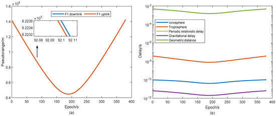
Figure 4.
(a) Largest single observation arc of F1 frequency and (b) various delay components in the signal transmission process.
Finally, the verification and analysis platform constructed in Figure 3 was used to verify and analyze the simulation data of the low-orbit spacecraft, Xi’an.
3.2. Space-to-Ground Time Synchronization Performance Analysis
The accuracy of space-to-ground time synchronization is mainly affected by the measurement noise of space-to-ground microwave links and unmodeled system errors. The accuracy of the system error modeling determines the accuracy limit that the space-to-ground link can achieve based on the premise that the measurement noise of the space-to-ground microwave link can reach the order of picoseconds. Combining Equations (5)–(12), the accuracy of various error correction models is mainly affected by orbital errors, and the contribution to orbital errors mainly comes from errors in precision orbit determination, phase center calibration, and attitude. According to engineering index requirements and experience, the use of low-orbit-spacecraft precision orbit determination algorithms can basically achieve an orbit determination accuracy within 10 cm afterward [34]. The phase center calibration accuracy can theoretically reach 1–2 mm, and the attitude error range is usually within approximately 0.02° (72 arc seconds (as)). Based on the new space-to-ground two-way time synchronization method proposed in this study, using simulation settings for low-orbit spacecraft and ground stations equipped with high-performance atomic clocks, precision orbit determination products were subsequently employed to compensate for system errors such as motion delay errors and relativistic effect errors and to solve the relative clock difference between space and the ground. A quadratic polynomial fitting was performed on the final clock error solution to deduct the inherent trend in the spaceborne atomic clock. The fitting residual error contains the systematic error correction, which reflects the accuracy of the intersatellite time comparison. The time synchronization error (fitting residual) under different error conditions is shown in Figure 5.

Figure 5.
Time synchronization error under different error settings. (a) The time synchronization error distribution of different attitude errors when the control phase center calibration error is 1 mm and the orbit determination error is 10 cm. (b) The time synchronization error distribution of different phase center calibration errors when the control attitude error is 0.02° (72 as) and the orbit determination error is 10 cm. (c) The time synchronization error distribution of different orbit determination errors when the control attitude error is 0.02° (72 as) and the phase center calibration error is 1 mm.
Figure 5a and Table 2 show the two-way time synchronization under different attitude angles. The results indicate that as the attitude angle increases, the accuracy of the two-way time synchronization decreases. The attitude is within the range of 100 as and the uncertainty of the two-way time synchronization error is better than 1.32 ps. Figure 5b and Table 3 show that when only the phase center calibration error is considered, the RMS of the two-way time synchronization error will increase with the phase center calibration error. The two-way time synchronization uncertainty is better than 1.39 ps after error corrections have been performed on each term. Under different orbit determination errors, the two-way time synchronization error and its error uncertainty are shown in Figure 5c and Table 4. When the POD error is less than 25 cm, the two-way time synchronization error uncertainty is not more than 1.44 ps. The above results show that the orbit determination error has the greatest impact on the two-way time synchronization results, followed by the phase center calibration error and the attitude error.
Table 2.
Two-way time synchronization accuracy (RMS) under different attitude errors.
Table 3.
Two-way time synchronization accuracy (RMS) under different phase center calibration errors.
Table 4.
Two-way time synchronization accuracy (RMS) under different orbit determination errors.
Based on the analysis results of the above simulation experiments, two-way time synchronization is closely related to the orbit, attitude, and phase center calibration errors. When the space-to-ground microwave link has an orbit accuracy better than 10 cm, an attitude error better than 0.02°, and a phase center calibration error within 1 mm, the new space-to-ground two-way time synchronization method proposed in this paper is used to further calculate the space-to-ground relative clock difference after performing processing and error calibration (Figure 6), while fully considering other major errors in the time synchronization process (ignoring equipment errors). After the measurement data have been processed and the error has been calibrated, the new synchronization method calculates the space-to-ground relative clock difference (Figure 6a). The space-to-ground time synchronization result (Figure 6) is then obtained, and the results show that the peak-to-peak value of the fitting residuals is better than 4 ps and the time synchronization accuracy is greater than 1.5 ps. By synthesizing the influence of various error factors on the two-way time synchronization, the abovementioned time synchronization method can achieve sub-ps-level link accuracy within the allowable error range, but the fitting residuals in Figure 6b still show a trend, which may be caused by the residual orbit errors.
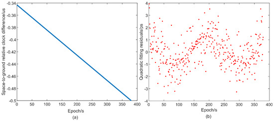
Figure 6.
Space-to-ground time synchronization result. (a) Relative clock difference between the space clock and the ground clock. (b) Fitting residuals of the relative clock difference.
From Figure 7, it can be seen that after comparing ground clocks at high resolution on a Xi’an basis using a link in the microwave domain, the link stability should reach approximately 0.7 ps after 100 s of integration. Therefore, the proposed single-frequency space-to-ground time synchronization method is effective for realizing ps-level time transfer.
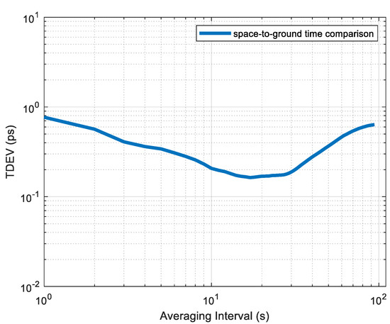
Figure 7.
Performance objective of the space-to-ground time and frequency transfer expressed in time deviation (TDEV).
4. Conclusions
This study presented a single-frequency space-to-ground time synchronization method based on a low-orbit spacecraft in a highly dynamic environment. A simulation verification platform was built by integrating actual application scenarios. The simulation data were used to verify the space-to-ground time synchronization method based on the single-frequency dual-antenna mode. The simulation data were used to verify the effectiveness of the space-to-ground time synchronization method based on the single-frequency dual-antenna mode and related error processing methods. The time synchronization results of different error factors and their influence on the time synchronization accuracy were analyzed. Based on the simulations and analysis, the following conclusions can be drawn.
Without considering equipment delay errors, the system error modeling accuracy determines the accuracy limit of the space-to-ground microwave link. When the influences of the errors involving the attitude, phase center, and orbit on the time synchronization errors are considered separately, the attitude has less influence on the two-way time synchronization errors, followed by the phase center calibration error. The POD error has the greatest impact on the two-way time synchronization error.
The control attitude error is 72 as (0.02°), the phase center calibration error is 1 mm, and the POD error is 10 cm (three-axis). Without considering other error factors, the time synchronization accuracy will be better than 1.5 ps and the TDEVof the transfer link will be approximately 0.7 ps @ 100 s after adopting the two-way time synchronization method in this paper and performing error correction, which can result in an ultrahigh-precision time synchronization between space and the ground.
As only the link level is modeled to eliminate errors and equipment measurement noise and other errors are ignored, additional disturbances and noise sources will affect the time synchronization performance. The actual time synchronization performance of the single-frequency mode may be slightly lower than the current simulation results.
Although the two-way ranging signal under the single frequency point and dual antennas can effectively eliminate the influence of the atmosphere, the safety distance between the dual antennas will introduce additional interference in the elimination of various errors. Further improvement in the method based on the structure and error correction model should be considered.
Author Contributions
Conceptualization, Y.G. and Y.B.; data curation, Y.G.; formal analysis, Y.G. and S.G.; funding acquisition, Y.B., S.G., X.L. and S.Z.; methodology, Y.G.; project administration, Y.G. and Z.P.; resources, S.G., X.L. and S.Z.; software, Y.G.; validation, Y.G., Y.L. and Z.P.; writing—original draft, Y.G., writing—review and editing, Y.G. and Y.B. All authors have read and agreed to the published version of the manuscript.
Funding
This research was supported by the (1) National Natural Science Foundation of China (11873009), (2) CAS ”Light of West China ” Program (E016YR1R), (3) Shaanxi Provincial Talents Plan (E039SB1K), and (4) National Natural Science Foundation of China Youth Fund Project (11903039).
Institutional Review Board Statement
Not applicable.
Informed Consent Statement
Not applicable.
Data Availability Statement
The simulation data are available from the corresponding author upon request.
Acknowledgments
Thanks to the experimental platform provided by the time-frequency comparison and analysis team of the National Time Service Center of the Chinese Academy of Sciences, and thanks to Liu Wanke, Zhou Chen, Gong Xuewen, and Zhao Jiaqi from Wuhan University, and Sun Leyuan from the National University of Defense Technology for their help in completing the MWL data simulation system.
Conflicts of Interest
The authors declare no conflict of interest.
References
- Yuan, Y.; Wang, B.; Wang, L. Fiber-based joint time and frequency dissemination via star-shaped commercial telecommunication network. Chin. Phys. B 2017, 26, 080601. [Google Scholar] [CrossRef]
- Pan, J.; Hu, X.; Zhou, S.; Tang, C.; Guo, R.; Zhu, L.; Tang, G.; Hu, G. Time synchronization of new-generation BDS satellites using inter-satellite link measurements. Adv. Space Res. 2018, 61, 145–153. [Google Scholar] [CrossRef]
- Yang, W.; Meng, W.; Han, W.; Xie, Y.; Ren, X.; Hu, X.; Dong, W. Advances in Atomic Clock Ensemble in Space of Europe and Ultraprecise Time and Frequency Transfer. Prog. Astron. 2016, 34, 221. [Google Scholar]
- Laurent, P.; Abgrall, M.; Jentsch, C.; Lemonde, P. Design of the cold atom PHARAO space clock and initial test results. Appl. Phys. B. 2006, 84, 683–690. [Google Scholar] [CrossRef]
- Cacciapuoti, L.; Salomon, C. Space clocks and fundamental tests: The ACES experiment. Eur. Phys. J. Spec. Top. 2009, 172, 57–68. [Google Scholar] [CrossRef]
- Zhang, X. System design and key technologies of high accuracy time and frequency microwave link for spaces station. Telecommun. Eng. 2017, 57, 407–411. [Google Scholar]
- Laurent, P.; Massonnet, D.; Cacciapuoti, L.; Salomon, C. The ACES/PHARAO space mission. Comptes Rendus Phys. 2015, 16, 540–552. [Google Scholar] [CrossRef]
- Savalle, E.; Guerlin, C.; Delva, P.; Meynadier, F.; Poncin-Lafitte, C.L.; Wolf, P. Gravitational redshift test with the future ACES mission. Class. Quantum Gravity 2019, 36, 245004. [Google Scholar] [CrossRef]
- Heb, M.P.; Stringhetti, L.; Hummelsberger, B.; Hausner, K.; Stalford, R.; Nasca, R.; Cacciapuoti, L.; Much, R.; Feltham, S.; Vudali, T. The ACES mission: System development and test status. Acta Astronaut. 2011, 29, 929–938. [Google Scholar]
- Cacciapuoti, L.; Much, R.; Feltham, S.; Nasca, R.; Vudali, T.; Hess, M.P.; Stringhetti, L.; Salomon, C. ACES status at completion of the engineering models phase. In Proceedings of the 2010 European Frequency and Time Forum, Noordwijk, The Netherlands, 13–16 April 2010; pp. 1–10. [Google Scholar] [CrossRef]
- Delva, P.; Meynadier, F.; Le Poncin-Lafitte, C.; Laurent, P.; Wolf, P. Time and frequency transfer with a MicroWave Link in the ACES/PHARAO mission. In Proceedings of the 2012 European Frequency and Time Forum, Gothenburg, Sweden, 23–27 April 2012; pp. 28–35. [Google Scholar]
- Origlia, S.; Pramod, M.S.; Schiller, S.; Singh, Y.; Viswam, S.; Bongs, K.; Hafner, S.; Berbers, S.; Dorscher, S.; Al-Masoudi, A. An optical lattice clock breadboard demonstrator for the I-SOC mission on the ISS. In Proceedings of the Lasers & Electro-optics Europe & European Quantum Electronics Conference IEEE, Munich, Germany, 25–29 June 2017; p. 1. [Google Scholar]
- Xu, M.; Shi, W. Development of Deep Space Radio Ranging and Velocity Measurement Technology. J. Deep. Space Explor. 2018, 5, 140–146. [Google Scholar]
- Michalak, G.; Glaser, S.; Neumayer, K.H.; König, R. Precise orbit and Earth parameter determination supported by LEO satellites, inter-satellite links and synchronized clocks of a future GNSS. Adv. Space Res. 2021, 68, 4753–4782. [Google Scholar] [CrossRef]
- Seidel, A.; Hess, M.P.; Kehrer, J.; Schafer, W.; Kufner, M.; Siccardi, M.; Cacciapuoti, L.; Aguilar Sanches, I.; Feltham, S. The ACES Microwave Link: Instrument Design and Test Results. In Proceedings of the 2007 IEEE International Frequency Control Symposium Joint with the 21st European Frequency and Time Forum, Geneva, Switzerland, 29 May–1 June 2007; p. 1295. [Google Scholar]
- Liu, Y.; Li, X. Super-high accurate new metho d of common-view time comparison based on space station. Acta Phys. Sin. 2018, 67, 68–79. [Google Scholar]
- Bai, Y.; Guo, Y.; Wang, X.; Lu, X. Satellite-ground two-way measuring method and performance evaluation of BDS-3 inter-satellite link system. IEEE Access 2020, 8, 157530–157540. [Google Scholar] [CrossRef]
- Liu, Y.; Li, X. Effect of Orbit Error on Space Station Time Comparison and Calibrating Method. J. Astronaut. 2019, 40, 345–351. [Google Scholar]
- Meynadier, F.; Delva, P.; Le Poncin Lafitte, C.; Guerlin, C.; Laurent, P.; Wolf, P. ACES Micro-wave link data analysis: Status update. In Proceedings of the Journées Systèmes De Référence Spatio Temporels Scientific Developments from Highly Accurate Space Time Reference Systems, Paris, France, 16–18 September 2013; pp. 134–135. [Google Scholar]
- Cacciapuoti, L. I-SOC Scientific Requirement. 2017. Available online: http://www.exphy.uni-duesseldorf.de/PDF/SCI-ESA-HRE-ESR-ISOC_Iss.1.1_Approved.pdf (accessed on 1 December 2021).
- Pütz, C.; He, M.P.; Hummelsberger, B.; Hausner, K.; Prochazka, I. Aces mission status and outlook. In Proceedings of the 62nd International Astronautical Congress, Cape Town, South Africa, 3–7 October 2011; Volume 1, pp. 495–508. [Google Scholar]
- Cacciapuoti, L.; Armano, M.; Much, R.; Sy, O.; Salomon, C. Testing gravity with cold-atom clocks in space: The ACES mission. Eur. Phys. J. D 2020, 74, 164. [Google Scholar] [CrossRef]
- Yang, D.; Liu, Y.; Li, G.; Zhao, Q.; Yang, Z. Research on Communication Delay Model for Narrow Beam Inter-satellite Links in a TDMA System. In Proceedings of the China Satellite Navigation Conference (CSNC) 2017 Proceedings, Shanghai, China, 23–25 May 2017; pp. 3–9. [Google Scholar]
- Hobiger, T.; Piester, D.; Baron, P. A correction model of dispersive troposphere delays for the ACES microwave link. Radio Sci. 2013, 48, 131–142. [Google Scholar] [CrossRef]
- Pan, J.; Hu, X.; Tang, C.; Zhou, S.; Li, R.; Zhu, L.; Tang, G.; Hu, G.; Chang, Z.; Wu, S. System error calibration for time division multiple access inter-satellite payload of new-generation Beidou satellites. Chin. Sci. Bull. 2017, 62, 2671–2679. [Google Scholar] [CrossRef][Green Version]
- Zhu, J. Research on Determination and Time Synchronizing of Navigation Satellite Based on Crosslinks; National University of Defense Technology: Changsha, China, 2011. [Google Scholar]
- Guo, Y.; Bai, Y.; Gao, S.; Pan, Z.; Han, Z.; Gao, Y.; Lu, X. A SatelliteGround Precise Time Synchronization Method and Analysis on Time Delay Error Caused by Motion. In Proceedings of the China Satellite Navigation Conference (CSNC) 2021 Proceedings, Nanchang, China, 26–28 May 2021; Volume 3, pp. 158–171. [Google Scholar]
- Huang, W.; Kang, J.; Zhang, L.; Li, J. The Principle and Method of Beidou Satellite Navigation and Positioning; Science Press: Beijing, China, 2019; p. 123. [Google Scholar]
- Sun, L.; Gao, S.; Yang, J.; Xiao, F.; Fang, Y.; Feng, S. Relativistic Effect in the Two-Way Time Comparison Between Navigation Satellites. In Proceedings of the China Satellite Navigation Conference (CSNC) 2021 Proceedings, Nanchang, China, 26–28 May 2021; Volume 3, pp. 95–104. [Google Scholar]
- Chen, H.; Wu, H.; Zhou, M.; Qi, J. Orbit Engineering Application and STK Simulation for Microsatellite; Science Press: Beijing, China, 2016; p. 63. [Google Scholar]
- Lv, H. Research on method of Satellite-Ground Time Synchronization Base on Ka Band ISL System of BDS; University of Chinese Academy of Sciences: Beijing, China, 2017. [Google Scholar]
- Li, K.; Zhou, X.; Wang, W.; Gao, Y.; Zhao, G.; Tao, E.; Xu, K. Centimeter-Level Orbit Determination for TG02 Spacelab Using Onboard GNSS Data. Sensors 2018, 18, 2671. [Google Scholar] [CrossRef] [PubMed]
- Meynadier, F.; Delva, P.; Poncin-Lafitte, C.L.; Guerlin, C.; Wolf, P. Atomic clock ensemble in space (ACES) data analysis. Class. Quantum Gravity 2018, 35, 035018. [Google Scholar] [CrossRef]
- Weinbach, U.; Schon, S. Improved GPS receiver clock modeling for kinematic orbit determination of the GRACE satellites. In Proceedings of the 2012 European Frequency and Time Forum, Gothenburg, Sweden, 23–27 April 2012; pp. 157–160. [Google Scholar]


Publisher’s Note: MDPI stays neutral with regard to jurisdictional claims in published maps and institutional affiliations. |
© 2022 by the authors. Licensee MDPI, Basel, Switzerland. This article is an open access article distributed under the terms and conditions of the Creative Commons Attribution (CC BY) license (https://creativecommons.org/licenses/by/4.0/).