Article

Estimation of Human Body Height Using Consumer-Level UAVs

1
European Maritime Safety Agency, Surveillance Unit—Remotely Piloted Aircraft Systems, Praça Europa 4, 1249-206 Lisbon, Portugal
2
NOVA Information Management School (NOVA IMS), Universidade Nova de Lisboa, Campus de Campolide, 1070-312 Lisbon, Portugal
*
Author to whom correspondence should be addressed.
Remote Sens. 2022, 14(23), 6176; https://doi.org/10.3390/rs14236176
Submission received: 1 October 2022 / Revised: 24 November 2022 / Accepted: 4 December 2022 / Published: 6 December 2022

Abstract

:
Consumer-level UAVs are often employed for surveillance, especially in urban areas. Within this context, human recognition via estimation of biometric traits, like body height, is of pivotal relevance. Previous studies confirmed that the pinhole model could be used for this purpose, but only if the accurate distance between the aerial camera and the target is known. Unfortunately, low positional accuracy of the drones and the difficulties of retrieving the coordinates of a moving target like a human may prevent reaching the required level of accuracy. This paper proposes a novel solution that may overcome this issue. It foresees calculating the relative altitude of the drone from the target by knowing only the ground distance between two points visible in the image. This relative altitude can be then used to calculate the target-to-camera distance without using the coordinates of the drone or the target. The procedure was verified with real data collected with a quadcopter, first considering a controlled environment with a wooden pole of known height and then a person in a more realistic scenario. The verification confirmed that a high level of accuracy can be reached, even with regular market drones.

1. Introduction

Drones, or unmanned aerial vehicles (UAVs), are employed in urban areas to perform a wide range of activities, including people detection [1]. Within this context, one of the key elements is the capacity to detect a person of interest. This can be done via face recognition, although this implies that the face of the person is visible in the imagery. Therefore, other physical or behavioral human characteristics (also called Soft Biometric traits) must be considered to enhance the likelihood of recognition. Among others, the stature of the person is one of the most distinctive traits [2]. There is a significant number of studies in the literature dedicated to this purpose, but most of them have been developed considering fixed installations (surveillance cameras).
In recent years, remotely piloted drones are gaining popularity for surveillance and law enforcement purposes, especially in urban areas, due to their versatility and low costs. The capacities of these air vehicles are further empowered by Artificial Intelligence (AI), which provides tremendous support for rapid and effective decision making. At the same time, they are still lacking in critical performance elements, such as low positional accuracy. Previous studies that focused on target height estimation using aerial surveillance cameras [3] confirmed that a pinhole camera model after camera calibration and image distortion compensation is an efficient approach for measuring the height of the target, especially when dealing with real-time applications like surveillance. The height of the target, centered in the image and standing vertically from the ground, can be performed considering a single image acquired with a regular Electro-Optical camera installed into steerable gimbals. The approach requires a limited number of intrinsic and extrinsic parameters, namely focal length, number of pixels spanning the features, Pitch angle, and camera-to-target distance. The latter is the most critical parameter because it may not be easy to retrieve and, at the same time, the uncertainty associated with this parameter may have a strong impact on the accuracy of the estimation [3]. Without a very accurate camera-to-target distance, it is not be possible to reach a level of accuracy adequate for human body height estimation. Ideally, we should know the exact coordinates of the drone and the exact coordinates of the target to retrieve their Euclidian distance, but this condition is rarely met due to the low positional accuracy of the drones. Moreover, it is rather difficult to retrieve the coordinates of a moving target like a human. The target-to-drone distance could be also retrieved by knowing the difference in elevation between the drone and the point where the target is but, once again, the accuracy related to the position of the UAVs and the exact elevation of the target are limiting factors considering the required level of accuracy. Spatial Resection methods [4] could be used to retrieve the world coordinate of the UAV using the accurate coordinates of enough Ground Control Points (GCP) visible in the image. However, practical experience has shown that this approach is very often unsuitable for real surveillance scenarios, due to two main reasons: (a) it is not often possible to have in the image scene the required number of GCP (like building corners) to update this method, (b) Surveillance activities in urban areas is usually performed by law enforcement personnel without experience in programmatic procedures and unable (or even reluctant) to collect ground measures (like accurate GPS for GCPs) or handling geospatial data. It is here proposed a novel approach to retrieve the relative elevation of the drone from the target to eventually determine the accurate target-to-camera distance to feed the pinhole model. This approach foresees knowing only the ground distance between two points visible in the image. There is no need for GPS coordinates or other geospatial information, just a regular length expressed in units (meters). The practical experience has demonstrated that this is a suitable approach that can be adopted by non-experienced personnel involved in UAV surveillance because (a) no prior knowledge of photogrammetry or GIS is required, and (b) it can be retrieved if known objects are visible in the scene (e.g., distance between the wheels of a car of known type), (c) topographic maps or even publicly available web services like Google Earth can be used to find this distance (although this may introduce an error, which will be discussed later in this paper), (d) it can be measured directly on the spot before the flight or after the flight without specialized equipment (just a metric ruler or a measuring tape). The accuracy of the method could be further enhanced by using multiple pictures or video sequences [5]. Finally, future developments should be focused on how to fully automatize the process of retrieving the distance between two points in the UAV imagery. This could be achieved, for example, by linking UAV data with satellite orthophotos. The combination of AI algorithms for the automatic detection of people in the imagery combined with the proposed method could sensibly enhance the effectiveness of UAV-based surveillance activities.
This paper is divided into two main sections. The first section describes the methods considered for the estimation of the human target, and the second provides results of the field tests for the validation of the methods. The first paragraph of the methods provides a gentle description of the background theory, the pinhole model, and the distortion compensation. After this, it provides a brief description of how the target height—can be estimated considering gimbaled cameras mounted in UAVs. The third paragraph of the first section describes the procedure to retrieve the vertical target-to-camera distance. The final part is dedicated to performing an uncertainty analysis to define the error associated with the target height estimation using the proposed approach. The procedure was verified with real data collected with a lightweight quadcopter, first using a wooden pole of known height in a controlled environment and then considering a person as a target in a more realistic case scenario. Finally, a discussion on possible future developments is provided. More specifically, we propose the possibility of automatizing the detection of the target, estimating an accurate height when the target is not standing straight from the ground, and considering the presence of multiple targets.

2. Methods

2.1. Pinhole Model and Image Distorition Compensation: Background Theory

The pinhole camera model considers a central projection using the optical center of the camera and an image plane (that is perpendicular to the camera’s optical axis [6]). This model represents every 3D world point P (expressed by world coordinates x p , y p , z p ) by the intersection between the image plane and the camera ray line that connects the optical center with the world point P (this intersection is called the image point). The pinhole camera projection can be described by the following linear model:
[ μ i ν i 1 ] = K [ R T ] [ x p y p z p 1 ]
K is the calibration matrix [7], defined as follows:
K = [ f μ γ μ 0   0 f ν ν 0 0 0 1 ]  
f μ and f ν   represent, respectively, the focal length and the focal length affected by the compression effect in the ν axis expressed in pixels. μ 0   and ν 0 are the coordinates of the principal point, which is normally a few pixels displaced from the image center, with the origin in the upper left corner. γ   is the skew coefficient between the x and y axis. This latter parameter is very often 0. The focal length can also be expressed in metric terms (e.g., mm instead of pixels) considering the following expressions:
F x = f μ W μ w μ
F y = f ν W ν w ν
w μ and w ν   are, respectively, the image width and length expressed in pixels, W μ is the width and W ν the length of the camera sensor expressed in world units (e.g., mm). Usually, F x and F y have the same value, although they may differ due to several reasons such as flaws in the digital camera sensor or when the lens compresses a widescreen scene into a standard-sized sensor. In this paper, we will assume that F x =   F y = F and f μ = f ν = f . R and T in (1) are the rotation and translation matrices of the camera, respectively, in relation to the world coordinate system. These include the extrinsic parameters which define the so-called “camera pose”. R is defined, in this case, by the angles around the axes (X, Y, and Z) of the World Coordinate System needed for rotating the image coordinate system axes in order to get them coincident (or parallel) with the world coordinate system axes. In the case of rotation around the X axis by an angle θx, the rotation matrix Rx is given by (5) [7]:
R x = [ 1 0 0 0 cos ( θ x ) sin ( θ x ) 0 sin ( θ x ) cos ( θ x ) ]
Rotations by θy and θz about the Y and Z axes can be written as:
R y = [ cos ( θ y ) 0 sin ( θ y ) 0 1 0 sin ( θ y ) 0 cos ( θ y ) ]
R z = [ cos ( θ z ) sin ( θ z ) 0 sin ( θ z ) cos ( θ z ) 0 0 0 1 ]
A rotation R about any arbitrary axis can be written in terms of successive rotations about the X, Y, and finally Z axes, using the matrix multiplication shown in (8). In this formulation θx, θy and θz are the Euler angles.
R = R z R y R x
T is expressed by a 3-dimensional vector that defines the position of the camera against the origin of the world coordinate system. Scaling does not take place in the definition of the camera pose. Enlarging the focal length or sensor size provides the scaling.
The pinhole model does not consider that real lenses may produce several different non-linear distortions. The major defects in cameras is radial distortion, caused by light refraction differences along with the spherical shape of the lens [8]. Other distortions, like the tangential distortion, which is generated when the lens is not parallel to the imaging sensor or when several component lenses are not aligned over the same axis, have minor relevance in quality objectives and are not relevant for this study. The radial distortions can usually be classified as either barrel distortions or pincushion distortions, which are quadratic, meaning they increase as the square of the distance from the center. Removing a distortion means obtaining an undistorted image point, which can be considered as projected by an ideal pinhole camera, from a distorted image point. The correction can take place by taking into consideration radial distortion coefficients, which are specific to the lens under analysis. Please refer to other studies for a complete description of this well-known process [3,8]. Finally, it is necessary to underline that the radial shift of coordinates modifies only the distance of every pixel from the image center. Thus, to sensibly reduce processing time, it is possible to remove the distortion of only specific pixels [8] without necessarily performing the correction of the entire image.

2.2. Target Height Estimation Using Gimballed Cameras Mounted in UAVs

The camera is usually fitted into steerable gimbals, which may have the freedom to move around one, two or even three axes (which would be formalistically called one-gimbal, two-gimbal or three-gimbal configurations, [9]). In those cases where the gimbal has limited degrees of freedom, further steering capacity for the camera must be provided by the UAV itself via flight rotations. The parameters required for the transformation from the world coordinate system to the camera coordinate system (extrinsic parameters) can be obtained from positioning measurements (latitude, longitude, and elevation) and Euler angles (yaw, pitch, and roll). Regular GPS receivers, which are not subject to enhancements such as differential positioning, may be affected by a relevant positional error, especially in elevation. On the other hand, the orientation angles are measured by sensitive gyroscopes, which usually have a reasonably good relative accuracy [10]. Positioning systems, gyroscopes, and accelerometers are used by the IMU (Inertial Measurement Unit) which are essential components for the guidance and control of UAVs [9]. The camera can be oriented to have the target centered in the image plane, this is a common practice in UAV operations because usually supported by dedicated detection and tracking algorithms [11]. Each still image acquired by the UAV is usually accompanied by a set of camera and UAV flight information, stored as metadata. The amount of information stored varies from system to system. Advanced imaging equipment may provide a complete set of metadata in KLV (Key-Length-Value) format in accordance with MISB (Motion Imagery Standards Board) standards [12]. Lightweight UAVs available in the regular market are not always fitted with such advanced devices but, very often, are capable to store a minimum set of metadata, which includes onboard positioning coordinates, flight orientation, and camera orientation.
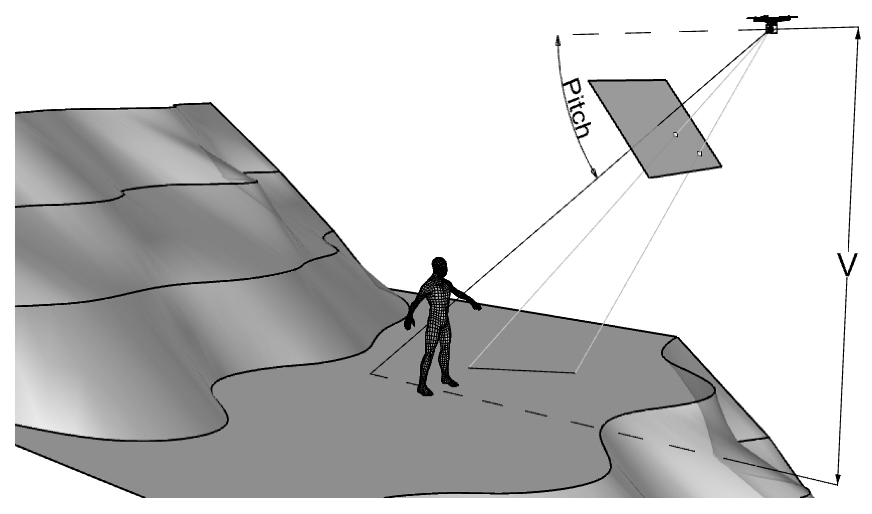
Estimating the height of a vertical target using a pinhole model and how it can be performed considering the case of UAV has been already treated in [3]. The camera must be centered on the target. The procedure requires the following parameters: camera-to-target distance, focal length, Pitch angle, pixels spanning upward from the image principal point r i and downward r j (which are respectively the distance of the undistorted image coordinates from the center of the points representing the top and the bottom of the target, the exact center of the image can therefore be an arbitrary pointing along with the target). The camera-to-target distance can be expressed by either horizontal distance (H) or vertical relative distance (V) in function of the Pitch angle, see Figure 1. With the mentioned parameters available, the height of the target can be estimated using simple trigonometric calculations, whose detailed description can be found in [3].
If the coordinates of the target and the coordinates of the aerial camera are known, then H and V are also known. Unfortunately, this theoretical approach does not work practically because of the low positional accuracy of the drones and the uncertainty in the position of a moving target like a human.
The next section describes a novel method to retrieve the height difference between the target and the camera center (V), considering only a horizontal distance between two points visible in the image.

2.3. Approach to Retrieve Height Difference between the Target and the Camera Center

As discussed in the previous section, the estimation of the target height requires to know the relative vertical position of the UAV regarding the target. Theoretically, this can be easily done by subtracting the elevation of the UAV and the elevation of the point where the target is. In urban areas, it is often possible to find the exact altitude of the target (the elevation of squares or streets is often well known). The problem lies in the accuracy related to the position of the UAVs: consumer-level aircraft do not reach a sufficient level of accuracy for the scope of estimating the target height (e.g., Phantom 4 PRO used in this research has a vertical uncertainty of ±0.5). It is here proposed a novel approach to retrieve V using only the horizontal distance between two points visible in the image. No need for GPS coordinates or other geospatial information, just a regular length expressed in meters.
Figure 2 shows the concept: the ground distance between two points visible in the image should be available (the coordinates of the points on the ground are not needed). This length can be of any dimension (if it is recognizable in the image) and oriented in any spatial direction, but it must be planar and at the same elevation as the target. Therefore, it should be either close to a target located in an uneven area or even farther, if the target is in a flat area (e.g., an open square). The parameter V, which represents, in this case, the height difference between the horizontal plane where the length lies and the center of the camera can be calculated by only knowing the image coordinates of the points, pitch and roll of the camera, and ground distance between the two points. No other info is required. This very limited amount of information is enough to calculate V because, as shown in Figure 1, it is not necessary to handle real-world coordinates: a local coordinate system with the origin arbitrarily located in the camera center and oriented is enough.
To explain how V can be calculated, let us assume that the camera is in an initial state comparable to the inertial frame (θx = θy = θz = 0, see Section 2.1) with the origin of the local coordinate system in the camera center. The center point of the image plane c has image coordinates equal to μ 0 and ν 0 but, considering the local system defined above, the coordinates (xc, yc, zc) of this point would be (see Figure 3):
c = ( f ,   0 ,   0 )
where f is the focal length expressed in pixels.
Let us now consider a generic point p in the image plane of coordinates μ p   and ν p . The coordinates (xp, yp, zp) of this point in the local system can be retrieved as follow:
p = ( f ,   ( μ 0   μ p )   ,   ( ν 0 ν p ) )
We want now to define the position of the point p in the local coordinate systems after the rotations defined by Euler angles. As shown in Figure 1 and Figure 2, the θz (yaw angle) is always equal to zero. Thus, the position of the point p remains unchanged, as well as the orientation of the image plane and the position of the center c. The rotation of the coordinates of the point p due to Pitch (θy) can be then calculated using Ry (see Equation (6) and Figure 3a,b).
The coordinates of the point p′ after rotation due to pitch (x′p, y′p, z′p) can be then calculated as follow:
[ x p y p z p ] = [ cos ( θ y ) 0 sin ( θ y ) 0 1 0 sin ( θ y ) 0 cos ( θ y ) ] [ x p y p z p ]
Similarly, it is possible to retrieve the coordinates of the image center c′ after Pitch rotation (x′c, y′c, z′c).
It is now necessary to apply the rotation due to Roll angle (θx) to finally determine the position of the point p″ in the defined local coordinate system after the necessary camera rotations. However, in this case, it is not possible to simply multiply the coordinates of the point p′ by the matrix Rx (see Equation (5)) because the axis along with the Roll rotation takes place (O-c′) is no longer aligned with the axis of the local coordinate system (see Figure 3c). In this case, it is necessary to apply a rotation along the axis O-c′ using the following sequence of rotations T (see [13] and [14] for further details):
[ T O c ] = [ R x ] 1 [ R y ] 1 [ R Roll ] [ R y ] [ R x ]
where:
R x = [ 1 0 0 0 z c Q y c Q 0 y c Q z c Q ]
R y = [ Q L 0 x c L 0 1 0 x c L 0 Q L ]
R z = [ cos ( θ x ) sin ( θ x ) 0 sin ( θ x ) cos ( θ x ) 0 0 0 1 ]
R y 1 = [ Q L 0 x c L 0 1 0 x c L 0 Q L ]
R x 1 = [ 1 0 0 0 z c Q y c Q 0 y c Q z c Q ]
And
L = x c 2 + y c 2 + z c 2 =   f
Q = y c 2 + z c 2
The coordinates of the point p″ (see Figure 3c) are therefore given as:
[ x p y p z p ] = [ T O c ] [ x p y p z p ]
Let us now consider Figure 4, where a and b are image points whose coordinates in the local coordinates system are (xa, ya, za) and (xb, yb, zb)—these coordinates can be defined according to the procedure described above. The plane π , in analogy with Figure 2, is the horizontal surface where the target lies. The point O, as extensively discussed, is the camera center which is considered here as the origin of the local coordinate system (0, 0, 0). The point Z, that lies on the plane π , is defined by the coordinates (0, 0, z π )— z π is the height of the camera from the plane π . A and B are points lying on the plane π . Their coordinates are not known but as already pointed out, the distance AB is a known parameter that needs to be converted in pixels.
We remind that the plane π , can be expressed by the following parametric equation:
cz π = d
where c and d are coefficients belonging to , and the points A and B can be given as follow:
A = t i Oa     π
B = t j Ob     π
where t 1 and t 2 are scalar coefficients, Oa = (xa, ya, za), and Ob = (xb, yb, zb). The goal of this approach is to calculate z π , which is the value required to calculate the height of the target (expressed with the symbol V in Figure 2), by knowing the distance AB, beside camera Pitch, Roll, image coordinates of the points a and b and intrinsic camera parameters.
We propose the following approach to retrieve the value of z π .
Let us consider another horizontal plane π 1 passing for one of the two points in the image plane, let’s say the point a in this case (see Figure 5a).
The point Z1 has coordinates equal to (0, 0, z π 1 ) but z π 1 is equal to z a , since the point Z1 and the point a are lying on the same horizontal plane π 1 . Therefore, the parametric equation of the plane π 1 is given as follows:
cz a = d
As seen before, c and d are coefficients belonging to .
Let’s now consider the point b’ (intersection of the vector Ob and the plane π 1 , see Figure 5b). The coordinates of this point can be calculated as follow:
( x   b     , y   b     ,   z   b   ) = ( t 1 x b   ,   t 1 y b   ,   t 1 z b )
Since the point b′ and the point a are lying in the same horizontal plane we can state that:
  t 1 z b =   z a
And so, we can retrieve the parameter t 1
t 1 = z a z b
Now that the scalar coefficient t 1 is known, the coordinates of the point b′ can be calculated and used to retrieve the distance a-b′ ( z a and z b are equal and therefore not considered in the equation below):
a b = ( x a x   b   ) 2 + ( y a y   b   ) 2
The triangle a-b′-Z1 and the triangle A-B- Z   are homologous (see Figure 5c,d). Considering that Z1 = (0, 0, z π 1 )   and Z = (0, 0, z π ) we can therefore say that
ab : z π 1 = AB : z π
Since AB is a known parameter and we managed to retrieve ab′ in the Equation (29), we can now finally calculate z π . This value, as mentioned already, can be used to calculate the height of the target.

2.4. Uncertainty Analysis

In this section, we analyze the error associated with the calculation of V taking into consideration the possible uncertainty of the parameters involved in the calculation. After this, the error generated in the calculation of V will be considered in the estimation of the target height.
Assuming an accurate correction of the distortion, the major source of relevant error may come from the pixel counting, the length of the straight line on the ground, and the pitch angle. To better analyze how the error may vary, 15 cases with different camera orientations (pitch values equal to 20, 25, 39.1, 45, and 60), distance of the line from the center of the image, and ground lengths were created using a spreadsheet. These cases (artificially created) gave us the possibility to have full control over all the parameters in order to isolate and analyze each uncertainty and calculate their combination. The results of this analysis are reported in Table 1.
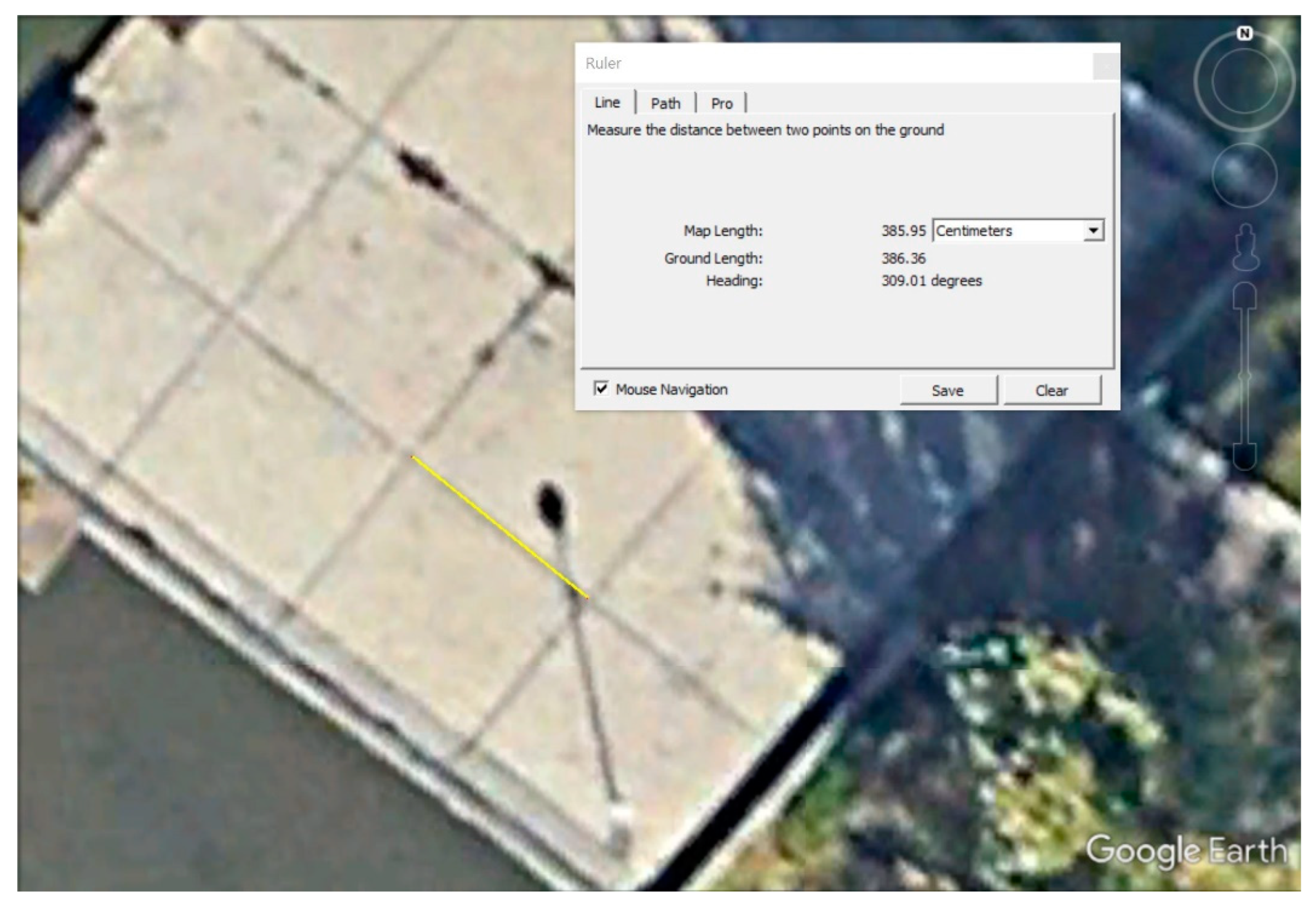
It was considered an error of ±1 pixel associated with the coordinates of the image point as well as ±1 pixel for the coordinates of the image point b. Regarding the accuracy related to the length of the line on the ground, three scenarios were considered: ±0.01 m, which is considered the case of measures accurately taken on the ground with a measuring tape; ±0.05 m, which is considered the case when the measures are taken on the ground with a measuring tape but we are less confident regarding their quality; ±0.50 m, which is the indicative value when the measure is not taken directly on the ground, but it is directly obtained from ortho-imagery or other sources like Google Earth [15]. Finally, an uncertainty of ±0.50° associated with the Pitch angles was deemed appropriate. The uncertainty associated with pixel position and error associated with ground length were combined considering the error propagation law:
δ = ( q real q Lenggt . Unc . ) 2 + ( q real q PixTop err ) 2 + ( q real q pitch err ) 2  
where δ denotes the error; q real   is the real V; q Lenht . Unc . is the calculated vertical camera-to-target distance when the length has the indicated uncertainty (0.01 m, 0.05 m and 0.5 m respectively); q Pix . Unc . is the uncertainty associated with the position of the image points a and b (1 pixel for a and 1 pixel for b, 2 pixels in total); q pitch err .is the uncertainty associated with the pitch angle (± 0.50°).
Table 1 also reports the calculation of V considering the mentioned uncertainties and the derived statistical error. Please note that for the three statistical errors (when length uncertainty is 1 cm, 5 cm, and 50 cm), the pixel uncertainty and pitch uncertainty would remain always the same.
The “Statistical error considering the uncertainty of Pitch angle” in Table 1 shows that the impact of error associated with the Pitch angle is rather relevant, in some cases comparable to a ground length error of 50 cm. This error increases substantially for low angles and when the distance from the ground is higher (i.e., higher V). While it would be reasonable to expect a systematic error in the measurement of the Pitch angle (especially when using consumer-level drones), the tests conducted did not often show errors clearly linked to erroneous pitch. However, this may randomly happen, and it should be taken into due consideration (see the next section for further analysis in this regard). A possible explanation might be that air surveillance is usually conducted in manual mode and the drone is usually hovering when a picture is taken to keep the target in the center. This approach might let the IMU stabilize and collect accurate pitch values (just a supposition that needs to be confirmed).
Considering the above, it is interesting to analyze the behavior of the statistical error considering only the other two variables (pixels and accuracy of the ground distance’s length), which is indicated as “Statistical error without the uncertainty of Pitch angle” in Table 1. The line from the image center (Defined as Euclidian distance from the center of the line to the center of the image), ground length, length of the line in pixels) against the statistical error were plotted against this error (see Figure 6). It can be noted that the error increases when the real V and Pitch are increasing (Figure 6a,b), while the error decreases with ground length (Figure 6c) and, apparently, it does not have a clear pattern when considering the distance from the center (Figure 6d). The most interesting plot is the length in pixels vs. statistical error (1 cm, Figure 6e), which shows a clear pattern: a length in pixels smaller than 100 results in a larger error, above 100 the error gets smaller and after 300 pixels it is constantly below 0.7 cm. The same behavior is also observed when the length in pixels is plotted against the statistical error (5 cm, Figure 6f): values of length (in pixels) smaller than 100 show a larger error, above 100 the error gets smaller and after 300 pixels the error is constantly below 0.7 cm. The same behavior is also shown for the 50 cm error (Figure 6g), but in this case, as expected, after 300 pixel-length the error does not get below 62 cm, while it reaches 13 cm for a length of almost 4000 pixels. To give an idea, a line of 70 cm on the ground generates a line of 300 pixels in the image plane when the UAV is at 3 m with a Pitch of 39 deg, while a line of 25 m is needed when the UAV is at 40 m.
Let us now consider the uncertainty associated with the estimation of the target’s height. As seen for the case above, a spreadsheet can be used to generate artificially 20 cases with a random position of the UAV looking at a vertical target (e.g., a pole) of 1.80 m. We can have full control over all the parameters to isolate and analyze each uncertainty associated with pixels and V. The position of the UAV with respect to the target ranges from 5 m to 50 m (horizontal distance from the target) and the camera pitch angle ranges between 5 deg to 75 deg. Two cases were considered: uncertainty associated with V equal to 0.05 m and uncertainty associated with V equal to 0.1 m. In both cases, the statistical error was generated considering an uncertainty of ±1 pixel in the counting of the pixels spanning the feature from the center to the bottom and ±1 pixel from the center to the top (2 pixels in total) and the uncertainty related to pitch (±0.50°). The statistical error was calculated considering Equation (30). However, taking into account the hypothesis that the error associated with the Pitch angle is not systematic, a statistical error considering Pitch uncertainty and without Pitch uncertainty was calculated. The results of this analysis are reported in Table 2. First, it is possible to appreciate that the Pitch error may prevent very accurate estimation, especially for low Pitch values and longer distances to the target. When the pitch error is not present, the error in the estimation of the target height will be 0.03 cm maximum V uncertainty of 5 cm, and 0.05 m maximum when the uncertainty of V is 0.1 m.
Let us now analyze the overall uncertainty in practical terms. According to the graphs in Figure 6, if we know the ground length of the line with an uncertainty of 0.01 m (i.e., measured on the ground), then any line with a length bigger than 250 pixels in the image plane could be used to estimate the height with an uncertainty of less than 0.03 m. If the uncertainty of the ground length is 0.05 m, then any line with length bigger than 300 pixels in the image plane could be used to estimate the height with an uncertainty of less than 0.05 m. Even if the uncertainty of ground length would be 0.5 m, it would be still possible to estimate the height of the target with reasonable accuracy (less than 5 cm) if the length of the line in pixels is longer than 4800 pixels. All this without considering the impact of the Pitch error. However, assuming once again that we may have a random error in the measurement of the Pitch angle, acquiring multiple images may mitigate its impact, as shown in the following section.

3. Results

Three separate tests were conducted to validate the proposed procedure using real data. In the first one, a pole was used as the target, with the drone flying in a controlled environment; several pictures were collected using the same ground distance as a reference. In the second, the same target (pole) and environment were considered, but only one image was acquired; the height estimation was obtained taking into account multiple reference distances. Finally, in the third test, a human being was used as the target in a more realistic urban scenario. The UAV employed during these tests was a DJI Phantom 4 PRO (a widely diffused multi-rotor platform of 1.388 kg), which is capable to generate ancillary tags in Exchangeable Image File Format (EXIF) of still images which provide, among other information, the position of the aircraft, aircraft orientation, and camera orientation at the moment of the acquisition of the still image. DJI Phantom 4 PRO has a GPS/GLONASS positioning system [16]. The camera sensor is a 1″ CMOS (Complementary Metal-Oxide Semiconductor) of 20 MP effective pixels with 5472 × 3648 pixels resolution and 13.2 mm × 8.8 mm size, lens focal length of 8.8 mm with no optical zoom and diagonal FOV (Field Of View) of 84° [16]. The camera of this UAV has a pivoted support (one-gimbal) with a single degree of freedom around the y-axis (pitch angle). Angular values are measured with an uncertainty of a few meters, clearly not enough to estimate with sufficient accuracy the height of a human target. This is a typical consumer-level UAV available in the regular market. The distortion coefficient k1 to be used for the pixel correction was retrieved through camera calibration techniques [17] developed with OpenCV via Python programming and is equal to 0.00275.

3.1. Field Test 1: Multiple Pictures of the Same Target

In this first field test, a wooden pole of 180 cm standing vertically from the ground was used as a target. This pole was used to avoid possible “collimation” with the top and bottom of the target (as we will see in the next section, it may not be easy to define the exact vertical bottom and top of a human being). The data were acquired in a flat area (an outdoor basketball court, see Figure 7). 10 still images were acquired with different camera pitch angles, and, in each acquired image, the principal point was always oriented over the pole (an arbitrary point along the pole, as described in Section 2.2). Images not properly oriented (principal point not located over the pole) were discarded and not used in this study. The camera Pitch angle and flight Roll angle of each image were extracted from EXIF tags, while the number of pixels spanning upward from the image principal point ( r i ) and downward ( r j ) were measured manually on screen.
Firstly, the same ground distance called “D” in Figure 7 was used to calculate the height of the UAV from the court surface considering the 10 images acquired (this distance was visible in every picture). This distance “D” is 3060 mm, measured on the spot from the internal football post to the other with a measuring tape. Table 3 reports the parameters of the acquired images for the calculation of the height and UAV elevation from the ground (V) and the results (V calculated using the approach described in the previous sections and the height of the target calculated using V). The error associated with the calculation of the height using the calculated V ranges from 0 to 0.03 m, which is compatible with an uncertainty of V of (approximately) 5 cm (see Table 2), except for the image DJI80 where the error is 0.15 m. The average height, considering all the acquired measurements, is 1.79 m. The uncertainty of the image DJI80, which is significantly larger than the others, may be caused by an error associated with the measurement of the Pitch angle (see the previous section). This test just confirms that it is better to estimate the height from multiple pictures to avoid the impact of random errors, possibly associated with Pitch angle.

3.2. Field Test 2: Single Picture of the Target, Multiple Ground Distances Considered

Image DJI126 (see Table 2) was used in this second test to calculate the height of the target. Several different distances visible in the image were considered. The distances among the points indicated with numbers from 1 to 12 in Figure 7 were measured on-site with a measuring tape (the internal corners were always used as a reference to obtain accurate measurements; the same corners were used to obtain the coordinate of the relevant pixels in the image).
The results in Table 4 show no relevant difference in terms of error by choosing one ground line instead of another, although a long line (in number of pixels) may give more chance to keep the error low. Considering multiple ground lines can be a good option, but it is not necessarily needed. Finally, we can underline that the error is never greater than 0.03 m, even if we choose a length smaller than 300 pixels (distance from point 1 to point 2).

3.3. Field Test 3: Real Case Scenario with a Human Being as Target

In this case, the target was a human being and the reference distance was a pattern made of stone tiles visible on the floor (see Figure 8). The UAV used was still the DJI Phantom 4 PRO. In alignment with the results of field test 2, multiple images of the same target were taken to reduce the possibility of getting an erroneous result due to random error. Moreover, a single ground line sufficiently long was chosen in every image as a reference (to be consistent, the same line was used for the three images).
In the three cases considered, the number of pixels spanning the target from the image center (represented with a blue cross in Figure 8a, image DJI243) was manually calculated: due to the perspective view, it is not always possible to pinpoint the exact top of the head of the human target (dashed line in Figure 8a). The reference distance was measured on-site using a measuring tape from the inner corners of the pattern on the ground (point A and point B in Figure 8b). The representation of the other images used in this test (DJI250 and DJI255) is given in Figure 8c,d. The same ground line was considered in all three cases. The parameters for the calculation of V and target height, as well as the results for the three images, are reported in Table 5.
The three cases gave similar results. Thus, we can assume that no random error occurred.
The distance between points A and B (Figure 8b) can also be retrieved using Google Earth (see Figure 9). This distance is clearly affected by a higher error compared with the measure realized on the spot with a measuring tape. This distance (3863 mm), when used for the calculation of V, returns a value of 9.52 m and an estimated height of the target equal to 1.68 m in DJI243, 1.70 m in the case of DJI250, and 1.69 m for DJI255, which are results pretty much in line with the analysis conducted in Section 2.4.

4. Discussion

There are two main elements related to the target’s metrics extraction that may make the difference during UAV surveillance operations: accuracy and rapidness.
Regarding accuracy, the method described in this paper provides an innovative solution capable to remove from the calculation elements that are highly prone to uncertainty, like the positional accuracy of the drone. This approach can, therefore, significantly improve the accuracy of the estimation, which may reach centimetric level accuracy (the accuracy needed for adequate people recognition via biometric traits). It requires the presence of a linear feature of known length in the scene, but this is a rather common element in urban areas, where people reconnaissance is needed the most. There are at least two additional elements that are not extensively treated in this study (considered out of scope) but they need to be at least mentioned: the spatial resolution of the imagery and the pose of the target. The images used in this study were intentionally taken relatively close to the target, with an average spatial resolution along the target that, in most of the cases, was of few millimeters (e.g., if we have 2000 pixels spanning along a vertical target of 1.80 m, the average spatial resolution of those pixels would be less than 1 mm). This allowed us to analyze the other parameters. However, in real case scenarios it is necessary to carefully consider this parameter because it may represent a limit to the accuracy of height estimation. Generically speaking, the spatial resolution of the pixels spanning a vertical target should be sensibly lower than the target resolution we want to achieve. Another source of error in the estimation of the height is related to the pose of the target. The person’s body height shall be measured while the person is standing upright [18]. If the person has a different pose, such as standing relaxed and leaning on one leg, we will manage to estimate just the height of the body in that specific pose. In the literature, the average relationship between the height of a person and its body parts (arms, hands, legs, etc.) is well known [19,20] so they might be used to retrieve the real body stature. Of course, further studies should be conducted in this respect to confirm the actual feasibility of this approach and the associated error. Alternatively, the height of the target could be estimated considering several images where the target assumes different poses.
Regarding rapidness, despite the calculations described in this paper need very little time to be performed, the prototype used for this work requires manual ingestion of the entry parameters (pitch, roll, pixels spanning the target, etc.), which is very time-consuming. Automatizing the acquisition of entry parameters is therefore one of the keys to the rapid execution of this method. This could be achieved through the development of a datalink with the drone, to obtain imagery and image acquisition parameters in real-time, and AI algorithms for the outlining of the target (person detection, [21,22]) and the counting of the pixels spanning the feature. The method implies the usage of linear features in the image, which can be retrieved using appropriate AI algorithms [23] and then presented to the operator via a GUI (Graphical User Interface), who should then ingest its length (measured, inferred, or obtained from other sources like Google Maps). Although more complicated, it would be also possible to co-registering the UAV image with Google satellite maps [24] to retrieve automatically the real length of the reference linear features appearing in the imagery.
Finally, it is necessary to underline that the approach for the calculation of the height considered in this paper is only applicable to a single target localized in the center of the image. Nowadays, air surveillance is still principally performed by human pilots and the regular procedures foresee centering the camera on a target. Therefore, the method described in this contribution will surely be useful. However, considering the development of AI algorithms, the possibility of estimating the height of multiple people in the image will have to be considered in future studies. Soon, drones will be greatly powered by AI algorithms capable of concurrently analyzing multiple features of the scene to retrieve a comprehensive surveillance picture.

5. Conclusions

This paper is mainly focused on how to retrieve the vertical target-to-camera distance, which is a critical parameter for the estimation of target height using a pinhole model after distortion compensation.
Previous studies confirmed that the pinhole model can be used for this purpose, but only if the accurate distance between the aerial camera and the target is known. This paper proposes a novel solution that foresees knowing only the ground distance between two points visible in the image. There is no need for GPS coordinates of the drone or target. Practical experience has demonstrated that this is a suitable approach that can be adopted by non-experienced personnel involved in UAV surveillance. The distance can be measured directly on the spot, retrieved through features of know dimension visible in the scene (e.g., the distance between the wheels of a car of know type), or obtained via topographic maps and publicly available web services like Google Earth.
This paper has also analyzed how the uncertainty of the parameters required in the calculation (real length of reference line on the ground and localization of the line in the image plane) are affecting the overall estimation. The analysis highlighted a very interesting fact: the error generated by the combination of uncertainties described is mainly guided by the length of the line in pixels in the image plane. In other words, if we could know the ground length of the line with an uncertainty of 0.01 m (i.e., measured on the ground), and any line with a length bigger than 250 pixels in the image plane could be used to estimate the height with an uncertainty of less than 0.03 m. If the uncertainty of the ground length is 0.05 m, then any line with a length larger than 300 pixels in the image plane could be used to estimate the height with an uncertainty of less than 0.05 m. Even if the uncertainty of ground length is 0.5 m, it would be still possible to estimate the height of the target with reasonable accuracy (less than 5 cm) if the length of the line in pixels is longer than 4800 pixels. However, the above does not take into account the error related to the pitch angle. The uncertainty analysis has clearly demonstrated that even a Pitch error of a half-degree may have a strong impact, preventing reaching accurate estimations. In other words, it would not make sense to use an accurate measure of the reference line on the ground if the drone cannot measure accurate Pitch values. The tests conducted in this study did not show a systematic presence of error related to Pitch angles: it appeared randomly in some sporadic cases. It should be anyway seriously considered, and activities to mitigate its impact, like collecting several images of the same target, should be always applied.
Three separate tests were conducted to validate the proposed procedure using real data. In the first, a pole was used as the target, with the drone flying in a controlled environment; several pictures were collected using the same ground distance as a reference. In the second, the same target (pole) was considered, but in this case only one image was acquired, and the height was estimated considering multiple reference distances. Finally, in the third test, a human being was used as the target in a more realistic urban scenario. The UAV used during these tests was a DJI Phantom 4 PRO, a widely diffused lightweight multi-rotor platform. The first test highlighted that employing multiple images may prevent the impact of random errors (probably due to erroneous calculation of Pitch angle by the drone when the image was taken). The outcomes of the second test of the analysis highlighted that there is no relevant difference in terms of error by choosing one ground line instead of another, although a long line (in the number of pixels) may give more chance to keep the error low. In alignment with the results of field tests 1 and 2, multiple images of the same target were taken, and, in every image, a single ground line sufficiently long was chosen as a reference. The real height of the human target was estimated rather accurately in each image, proving the efficiency of the method.
This paper considered a human target standing vertically from the ground, but this might always be the case (imagine a person walking, for example). The height of a person who is not standing perfectly vertically can be derived from relationships between body parts. Further studies should be conducted in this respect to confirm the actual feasibility of this approach and the associated error as well as how automated feature reconnaissance could be used to expedite the height estimation. Moreover, the possibility of analyzing multiple targets appearing in the image must be studied to reach a comprehensive surveillance scenario with the support of Artificial Intelligence algorithms.

6. Patents

The work described in this paper is part of a Patent Cooperation Treaty (PCT) application filled with the following provisional number: PCT/EP2022/069747. Please contact the Authors in case of interest in using the method, the owner of the Intellectual Property Rights (IPR) may grant usage permissions for non-lucrative or scientifically valuable projects.

Author Contributions

Conceptualization, A.T.; methodology, A.T.; software, M.C.; formal analysis, A.T.; resources, M.P.; writing—original draft preparation, A.T.; writing—review, M.P. and M.C.; supervision, M.P. and M.C.; project administration, M.P. and M.C. All authors have read and agreed to the published version of the manuscript.

Funding

This study was supported by grant DSAIPA/DS/0113/2019 from FCT (Fundação para a Ciência e a Tecnologia), Portugal. This work was also supported by national funds through FCT (Fundação para a Ciência e a Tecnologia), under the project—UIDB/04152/2020—Centro de Investigação em Gestão de Informação (MagIC)/NOVA IMS.

Data Availability Statement

The data used to support the findings of this study are available from the corresponding author upon request.

Acknowledgments

The authors would like to express their gratitude to NOVA Impact Office (https://novainnovation.unl.pt/nova-impact-office/, accessed on 15 November 2022) for all the support and valuable advice received regarding all the matters related to Intellectual Property Rights and collaboration with industry. Moreover, a special thank goes to: José Cortes for the support in data acquisition, Marta Lopes and Matias Tonini Lopes for the support in data acquisition and analysis, Francesca Maria Tonini Lopes for the logistical support.

Conflicts of Interest

The authors declare no conflict of interest.

Disclaimer

The content of this paper does not necessarily reflect the official opinion of the European Maritime Safety Agency. Responsibility for the information lies entirely with the authors.

References

  1. Gohari, A.; Ahmad, A.B.; Rahim, R.B.A.; Supa’at, A.S.M.; Abd Razak, S.; Gismalla, M.S.M. Involvement of Surveillance Drones in Smart Cities: A Systematic Review. IEEE Access 2022, 10, 56611–56628. [Google Scholar] [CrossRef]
  2. Kim, M.-G.; Moon, H.-M.; Chung, Y.; Pan, S.B. A Survey and Proposed Framework on the Soft Biometrics Technique for Human Identification in Intelligent Video Surveillance System. J. Biomed. and Biotechnol. 2012, 2012, 614146. [Google Scholar] [CrossRef] [PubMed] [Green Version]
  3. Tonini, A.; Redweik, P.; Painho, M.; Castelli, M. Remote Estimation of Target Height from Unmanned Aerial Vehicle (UAV) Images. Remote Sens. 2020, 12, 3602. [Google Scholar] [CrossRef]
  4. Kraus, K.; Harley, I. Photogrammetry: Geometry from Images and Laser Scans. In de Gruyter Textbook, 2nd ed.; de Gruyter: Berlin, Germany, 2007; ISBN 978-3-11-019007-6. [Google Scholar]
  5. Kainz, O.; Dopiriak, M.; Michalko, M.; Jakab, F.; Fecil’Ak, P. Estimating the Height of a Person from a Video Sequence. In Proceedings of the 2021 19th International Conference on Emerging eLearning Technologies and Applications (ICETA), Košice, Slovakia, 11 November 2021; IEEE: Piscataway, NJ, USA, 2021; pp. 150–156. [Google Scholar]
  6. Jeges, E.; Kispal, I.; Hornak, Z. Measuring Human Height Using Calibrated Cameras. In Proceedings of the 2008 Conference on Human System Interactions, Krakow, Poland, 25–27 May 2008; IEEE: Piscataway, NJ, USA; pp. 755–760. [Google Scholar]
  7. Sturm, P. Pinhole Camera Model. In Computer Vision; Ikeuchi, K., Ed.; Springer: Boston, MA, USA, 2014; pp. 610–613. ISBN 978-0-387-30771-8. [Google Scholar]
  8. Vass, G.; Perlaki, T. Applying and removing lens distortion in post production. In Proceedings of the 2nd Hungarian Conference on Computer Graphics and Geometry, Budapest, Hungary, 10 June 2003; pp. 9–16. [Google Scholar]
  9. Fahlstrom, P.G.; Gleason, T.J. Introduction to UAV Systems, 4th ed.; Aerospace Series; John Wiley & Sons: Chichester, UK, 2012; ISBN 978-1-119-97866-4. [Google Scholar]
  10. Padhy, R.P.; Verma, S.; Ahmad, S.; Choudhury, S.K.; Sa, P.K. Deep Neural Network for Autonomous UAV Navigation in Indoor Corridor Environments. Procedia Comput. Sci. 2018, 133, 643–650. [Google Scholar] [CrossRef]
  11. Minichino, J.; Howse, J. Learning OpenCV 3 Computer Vision with Python: Unleash the Power of Computer Vision with Python Using OpenCV, 2nd ed.; Packt Publishing: Birmingham, UK, 2015; ISBN 978-1-78528-384-0. [Google Scholar]
  12. MISB Standard 0902.7; Motion Imagery Sensor Minimum Metadata Set. MISB Standard: Springfiled, VA, USA, 2014.
  13. Lengyel, E. Mathematics for 3D Game Programming and Computer Graphics, 3rd ed.; Course Technology Press: Boston, MA, USA, 2011. [Google Scholar]
  14. Marschner, S.; Shirley, P. Fundamentals of Computer Graphics, 4th ed.; CRC Press, Taylor & Francis Group: Boca Raton, FL, USA, 2016; ISBN 978-1-4822-2939-4. [Google Scholar]
  15. Fonte, J.; Meunier, E.; Gonçalves, J.A.; Dias, F.; Lima, A.; Gonçalves-Seco, L.; Figueiredo, E. An Integrated Remote-Sensing and GIS Approach for Mapping Past Tin Mining Landscapes in Northwest Iberia. Remote Sens. 2021, 13, 3434. [Google Scholar] [CrossRef]
  16. DJI. Phantom 4 PRO/PRO+ User Manual; DJI: Shenzhen, China, 2017. [Google Scholar]
  17. Zhang, Z. A Flexible New Technique for Camera Calibration. IEEE Trans. Pattern Anal. Mach. Intell. 2000, 22, 1330–1334. [Google Scholar] [CrossRef] [Green Version]
  18. Vester, J. Estimating the Height of an Unknown Object in a 2D Image. Master Thesis, Royal Institute of Technology, Stockholm, Sweden, 2012. [Google Scholar]
  19. Winter, D.A. Biomechanics and Motor Control of Human Movement, 4th ed.; Wiley: Hoboken, NJ, USA, 2009; ISBN 978-0-470-39818-0. [Google Scholar]
  20. Guan, Y.-P. Unsupervised Human Height Estimation from a Single Image. J. Biomed. Sci. Eng. 2009, 02, 425–430. [Google Scholar] [CrossRef] [Green Version]
  21. Dalal, N.; Triggs, B. Histograms of Oriented Gradients for Human Detection. In Proceedings of the 2005 IEEE Computer Society Conference on Computer Vision and Pattern Recognition (CVPR’05), San Diego, CA, USA, 20–25 June 2005; IEEE: Piscataway, NJ, USA, 2005; Volume 1, pp. 886–893. [Google Scholar]
  22. Jia, H.-X.; Zhang, Y.-J. Fast Human Detection by Boosting Histograms of Oriented Gradients. In Proceedings of the Fourth International Conference on Image and Graphics (ICIG 2007), Chengdu, China, 22–24 August 2007; IEEE: Piscataway, NJ, USA, 2007; pp. 683–688. [Google Scholar]
  23. Crommelinck, S.; Bennett, R.; Gerke, M.; Nex, F.; Yang, M.; Vosselman, G. Review of Automatic Feature Extraction from High-Resolution Optical Sensor Data for UAV-Based Cadastral Mapping. Remote Sens. 2016, 8, 689. [Google Scholar] [CrossRef] [Green Version]
  24. Yuan, Y.; Huang, W.; Wang, X.; Xu, H.; Zuo, H.; Su, R. Automated Accurate Registration Method between UAV Image and Google Satellite Map. Multimed. Tools Appl. 2020, 79, 16573–16591. [Google Scholar] [CrossRef]
Figure 1. Graphical representation of the parameters required to calculate the height of the target of interest with a UAV using a pinhole model after image distortion correction. (Source: [3] with modifications).
Remotesensing 14 06176 g001
Figure 2. The relative elevation V of the UAV about the position of the target can be retrieved by knowing the distance between the two points visible in the image and lying in the plane of the target. (source: personal collection).
Remotesensing 14 06176 g002
Figure 3. Camera is in an initial state comparable to the inertial frame (θx = θy = θz = 0) (a). Black arrows represent the camera axes. The point O is the camera center and the origin of the local coordinate systems defined for this model; f is the focal length of the camera (oriented along the X axis); c is the image center; p is a generic point in the image plane. In the proposed model the Yaw angle (θz) is always equal to zero, therefore no system rotation is applied. The Pitch (θy) rotation around the Y axes and it generates the state represented graphically in (b). The Roll (θx) rotation needs to take place around the axes defined by O-c′ and generates the state represented graphically in (c). (Source: personal collection).
Remotesensing 14 06176 g003
Figure 4. Graphical representation of the parameters involved for the calculation of the height of the camera from the plane π. The description of the parameters is given in the text. (Source: personal collection).
Remotesensing 14 06176 g004
Figure 5. The horizontal plane π1 is introduced in the model described in Figure 4. In this graphical representation, the image plane is not shown (a). Focus on the plane π1 (b). Whole model (c) and visualization of the homologous triangles A-B-Z and a-b-Z1 (d). (Source: personal collection).
Remotesensing 14 06176 g005
Figure 6. Parameters indicated in Table 1 plotted against the statistical error without considering the uncertainty of the Pitch angle (Statistical Error of 1cm versus real V (a), Statistical Error of 1cm versus Pitch (b), Statistical Error of 1cm versus Ground length (c), Statistical Error of 1 cm versus Distance from Center (d), Statistical Error of 1 cm versus Length in Pixels (e), Statistical Error of 5 cm versus length in Pixels (f), Statistical Error of 50 cm versus Length in Pixels (g). Ground length uncertainty equal to 1 cm is considered. Pixel length is also plotted against the statistical error when Ground length uncertainty is equal to 5 cm and 50 cm.
Remotesensing 14 06176 g006
Figure 7. Example of still image (DJI126) acquired with DJI Phantom 4 PRO used for the field test 1 and 2. All the images used in the tests had as principal point located over the target (a wooden pole holds vertically from the ground). The reference distance used in the Test 1 is indicated as “D” in the picture, while the points are representing the ground lines used in the Test 2 (Source: Personal collection).
Remotesensing 14 06176 g007
Figure 8. Still picture DJI243 acquired with Phantom 4 PRO for the estimation of human target height (a) using as reference distance on the ground two inner corner points visible in the floor pattern (b). Image DJI250 (c) and image DJI255 (d) with the indication of points A and B.
Remotesensing 14 06176 g008
Figure 9. Measure of the distance between points A and B (Figure 8) performed in Google Earth (screenshot).
Remotesensing 14 06176 g009
Table 1. 15 cases with different orientation, distance from the center, and ground lengths were created considering consumer-level UAVs, such as DJI Phantom 4 PRO. These cases (artificially created) gave us the possibility to have full control over all the parameters to isolate and analyze each uncertainty and calculate their combination.
123456789101112131415
Pitch (o)39.139.139.139.12525252525254545602020
Length in Pixels26485604598551546264483652836111713764640
Dist. from Ima. Cent. (pixels)339810894555428126707632457936764435458621775452502959094125
Ground length (mm)480024001114712010,000324037517060010,00028005315171504810
Real V (UAV Height) (m)3.003.003.003.0012.001212.0112.0111.9812.002424.0240.025.996
Calculation of V
considering uncertainties
Uncertainty due to Pixel (m)0.000.020.000.140.020.110.120.720.920.030.340.93.250.040.03
Uncertainty due to Pitch (m)0.060.150.090.070.20.240.240.210.390.350.720.200.180.070.23
Ground length unc. = 1 cm (m)0.000.010.000.250.010.050.320.70.200.010.090.450.380.400.01
Ground length unc. = 5 cm (m)0.030.060.011.250.060.271.63.531.000.060.432.263.882.000.06
Ground length unc. = 50 cm (m)0.310.620.1312.510.602.4816.0135.329.980.604.2932.4138.7119.970.62
Statistical error considering uncertainty of Pitch angle
Statistical Error (1 cm) 0.060.150.090.290.200.270.421.031.020.350.801.033.280.410.23
Statistical Error (5 cm)0.070.160.091.260.210.381.623.611.410.360.902.445.062.000.24
Statistical Error (50 cm)0.320.640.1612.510.632.4916.0135.3310.030.704.3632.4238.8519.970.66
Statistical error without uncertainty of Pitch angle
Statistical Error (1 cm)0.000.020.000.290.020.120.341.000.940.030.351.013.270.400.03
Statistical Error (5 cm)0.030.060.011.260.060.291.603.601.360.070.552.435.062.000.07
Statistical Error (50 cm)0.310.620.1312.510.602.4816.0135.3310.020.604.3032.4238.8519.970.62
Table 2. 20 cases with a random position of the UAV. The table reports the parameters (pixels upwards and downwards for image center, pitch angle, and horizontal camera-to-target distance) with a target of 1.80 m.
1234567891011121314151617181920
H5611.312.329.729.231.733.939.74549.124.3178.110.97.717.625.49.18.3
V4.967.627.639.248.6515.9720.204.998.1914.3422.6122.1912.524.243.539.8814.0720.1419.5627.53
Pitch36.849.730.535.314.127.831.76.210.9172441.53319.511.449.937.237.263.772.8
Tot. Num of Pix.79948943036620717815119116013411215326469756936223916413970
Target Height Estimation (considering Pitch’s uncertainty)
Stat Error (unc. V = 5 cm) (m)0.030.020.020.010.010.010.000.020.010.010.010.010.010.030.030.010.010.000.010.01
Stat Error (unc. V = 10 cm) (m)
Target Height Estimation (without Pitch’s uncertainty)
0.040.030.030.020.020.020.010.040.020.010.010.010.020.050.050.020.010.000.010.00
Stat Error (unc. V = 5 cm) (m)0.030.020.020.020.050.020.020.100.070.050.030.010.020.040.060.010.020.010.030.04
Stat Error (unc. V = 10 cm) (m)0.040.030.030.020.020.020.010.040.020.010.010.010.020.060.050.020.010.000.010.00
Table 3. Data collected during the Field Test 1 and results.
DJI39DJI42DJI43DJI49DJI48DJI122DJI126DJI80DJI84DJI89
Pixels upwards (ri)306272158284358179288220108104
Pixels downwards (rj)1660170615485107602263010715771
Pitch angle (deg)11.711.719.336.820.314.733.72.725.843.3
Flight Roll Angle (deg)0.01.30.90.72.20.60.22.702.4
Ground Length “D” (mm)3060306030603060306030603060306030603060
Length in Pixels “D”15451548149910911182564518452421356
RESULTS
Calculated V2.192.22.753.14.910.21.510.819.6
Estimated height (m)1.791.791.801.821.791.801.831.651.831.83
Real Height (m)1.801.801.801.801.801.801.801.801.801.80
Error (m)0.010.010.000.020.010.000.030.150.030.03
Table 4. Data collected during the Field Test 2 with results of the analysis considering image DJI126.
From point111377779998812
To point234581110912118101210
Dist. ground (mm)1220453015,0005850515072605100103505100725052007260725010,310
Length in pixels 2609813221102810461312826209383112791047155015702715
RESULTS
Calculated V10.2810.1410.1810.1610.1810.0810.0910.1910.0710.1910.2110.2410.0910.25
Est. height (m)1.821.801.801.801.801.791.791.801.781.801.811.821.791.82
Real Height (m)1.801.801.801.801.801.801.801.801.801.801.801.801.801.80
Error (m)0.030.000.000.000.000.010.010.000.020.000.010.020.010.02
Table 5. Parameters related to the still image in Figure 8 and results of the analysis for the calculation of V and target height.
DJI243DJI250DJI255
Pixels upwards (ri)21922081
Pixels downwards (rj)126134167
Pitch angle (deg)39.115.426.8
Flight Roll Angle (deg)2.70.14.3
Ground Length A-B (mm)394039403940
Length in Pixels 687636810
RESULTS
Calculated V9.715.2511.22
Estimated height (m)1.721.731.72
Real Height (m)1.741,741.80
Error (m)0.020.010.02
Publisher’s Note: MDPI stays neutral with regard to jurisdictional claims in published maps and institutional affiliations.

