Article

Ground Clutter Mitigation for Slow-Time MIMO Radar Using Independent Component Analysis

1
Radar Research Lab, School of Information and Electronics, Beijing Institute of Technology, Beijing 100081, China
2
James Watt School of Engineering, University of Glasgow, University Avenue, Glasgow G12 8QQ, UK
3
Beijing Institute of Technology Chongqing Innovation Center, Chongqing 401120, China
*
Author to whom correspondence should be addressed.
Remote Sens. 2022, 14(23), 6098; https://doi.org/10.3390/rs14236098
Submission received: 31 October 2022 / Revised: 28 November 2022 / Accepted: 29 November 2022 / Published: 1 December 2022
(This article belongs to the Special Issue Theory and Applications of MIMO Radar)

Abstract

:
The detection of low, slow and small (LSS) targets, such as small drones, is a developing area of research in radar, wherein the presence of ground clutter can be quite challenging. LSS targets, because of their unusual flying mode, can be easily shadowed by ground clutter, leading to poor radar detection performance. In this study, we investigated the feasibility and performance of a ground clutter mitigation method combining slow-time multiple-input multiple-output (st-MIMO) waveforms and independent component analysis (ICA) in a ground-based MIMO radar focusing on LSS target detection. The modeling of ground clutter under the framework of st-MIMO was first defined. Combining the spatial and temporal steering vector of st-MIMO, a universal signal model including the target, ground clutter, and noise was established. The compliance of the signal model for conducting ICA to separate the target was analyzed. Based on this, a st-MIMO-ICA processing scheme was proposed to mitigate ground clutter. The effectiveness of the proposed method was verified with simulation and experimental data collected from an S-band st-MIMO radar system with a desirable target output signal-to-clutter-plus-noise ratio (SCNR). This work can shed light on the use of ground clutter mitigation techniques for MIMO radar to tackle LSS targets.

1. Introduction

Small drone detection using radar has attracted enormous attention in recent years [1,2,3]. With the rapid growth of the consumer drone market, unmanned aerial vehicles (UAVs) have become a significant threat to civil aviation, anti-terrorism, and private security. As a powerful sensor that can operate regardless the time and weather, radar plays an important role in tackling these low, slow and small (LSS) targets. Many systems [4,5,6,7,8,9,10,11,12,13] and techniques [14,15,16,17,18,19] focusing on LSS target detection in the field of radar have been researched and developed.
The early LSS target surveillance radar systems were modified from the maritime radar systems such as the MerlinTM Radar System from DeTect Inc. [20] and the initial product of Robin Radar Systems Inc. [21]. They consist of two maritime radar antennas that rotate along the azimuth and elevation to achieve quasi-3D detection. With the development of phased array radar, more LSS target detection systems have turned to utilize antenna array and digital beamforming technology to obtain better target detection performance [4,5]. In recent years, some relatively new radar concepts, such as multiple-input multiple-output (MIMO) radar [6,7,8], multistatic radar [9,10], and ubiquitous radar (which is also named holographic or staring radar) [11,12,13], have also been introduced to the field of LSS target detection.
There are two main challenges in detecting LSS targets. The first challenge is the poor target signal-to-clutter-plus-noise ratio (SCNR). Due to the low flying altitude of the small drones, the radar beam must have a rather small grazing angle. This significantly raises the ground clutter energy in the received signal. Considering the small radar cross-section (RCS) of LSS targets, the target SCNR is significantly reduced. Secondly, the slow flying, or hovering, velocity of the target renders the detection of LSS in slow-moving ground clutter via conventional techniques such as moving target indication (MTI) or moving target detector (MTD) ineffective. This is because ground clutter mainly consists of buildings, trees, cars, etc. The velocity spectrum spread of this clutter ranges from zero to tens of meters per second, which overshadows the speed of LSS targets. Thus, it is worth investigating clutter mitigation methods for LSS target detection.
Independent component analysis (ICA) [22,23,24] has aroused worldwide research interest in the field of signal processing since the 1990s. It has extensive applications in many fields such as communication, radar, image processing, acoustic processing, biomedical signal processing, and even financial data analysis [25]. Based on a MIMO system, the purpose of ICA is to simultaneously separate independent non-Gaussian components from observed multi-channel signals. This process can be used to help solve the ground clutter mitigation problem.
MIMO radar, as a typical multi-channel system, utilizes omnidirectional antennas and an orthogonal waveform in the transmitting stage, and then it forms a synthesized MIMO beam in the receiving stage. MIMO radar leverages waveform diversity to further increase the scale of the virtual array and spatial diversity [25,26,27]. A slow-time MIMO (st-MIMO) waveform [28,29,30] expands a conventional radar waveform by phase-coding the pulses of different channels to achieve orthogonal transmission and MIMO demodulation after pulse-Doppler (PD) processing. Although the unambiguous Doppler speed is divided by the number of Doppler sub-bands [31], st-MIMO is still feasible for slow-moving target detection with acceptable orthogonality and bandwidth efficiency.
Over the last few years, various techniques have been developed to tackle LSS targets from the radar detection stage to the parameter estimation stage and the target classification stage. Regarding methods used to enhance LSS target detection performance at the range-Doppler (r-D) level, one study [14] used the stationary point concentration technique to reduce the noise floor caused by transmitter leakage and increase the signal-to-noise ratio (SNR) of a UAV. Another study [15] adopted an iterative adaptive approach to enhance the Doppler resolution in an r-D map, which led to improved target detectability. For the parameter estimation stage, the authors of [16] proposed a long-time coherent integration method for maneuvering LSS targets to improve target estimation accuracy. Regarding the target classification stage, many works [2,17,18] focused on the micro-Doppler signature (m-DS) of UAVs. The numbers of m-DSs have been thoroughly analyzed among different types of UAVs and utilized to conduct target classification via multiple classifiers or neural networks.
There have been many studies in the field of clutter mitigation involving the aforementioned st-MIMO or ICA methods separately. Nevertheless, the combination of these two techniques while focusing on ground clutter mitigation in detecting LSS targets has been limited. For clutter mitigation involving st-MIMO, the authors of [28] developed spatial-time adaptive processing (STAP) in st-MIMO radar to mitigate multipath clutter. The spatial-time structure of st-MIMO was established, and a data covariance model, including target, direct path clutter, multipath clutter, jamming, and white noise, was defined. In [32], the beamspace st-MIMO, which can form virtual transmit nulls in directions that would result in multipath clutter returns in the main lobe of a radar system, was investigated. In [33], ground clutter was removed via principal components analysis (PCA) to enhance micro-Doppler feature extraction. For clutter mitigation involving the ICA or BSS methods, many works have focused on the multi-mode clutter suppression of over-the-horizon (OTH) radar. In [34,35], the spread-Doppler clutter caused by multi-mode propagation in OTH radar was suppressed via the second-order blind identification (SOBI) method. In addition, some works applied the BSS method in the field of main lobe jamming suppression [36].
In this study, we investigated the feasibility and performance of a ground clutter mitigation method combining the st-MIMO and ICA techniques in a ground-based MIMO radar focusing on LSS target detection. The main contributions of this work are as follows. Firstly, we propose a way to modulate ground clutter under the framework of st-MIMO. The ground clutter covariance was derived based on a Gaussian-shaped power spectrum. Combining the spatial and temporal steering vector of st-MIMO, a universal signal modelling including the target, ground clutter, and noise is provided. Secondly, we propose a st-MIMO-ICA processing scheme to separate the target signal from the received data including ground clutter plus noise. Mathematical proof that the signal model fits the framework of the ICA problem is provided. The multi-targets can be simultaneously separated via the proposed method. Finally, we validated our proposed st-MIMO-ICA method and evaluated its performance with both simulations and experiments using an S-band st-MIMO radar system developed in our previous work [6]. Comparisons with the PCA and adaptive techniques were performed, and the st-MIMO-ICA method showed the highest target output SCNR of the tested approaches.
The remainder of this paper is organized as follows. Section 2 describes the signal modeling of the st-MIMO radar and the ground clutter modulation in st-MIMO. Section 3 describes the signal modeling for conducting ICA and proposes the st-MIMO-ICA method. Section 4 presents the simulation and experimental results for the performance of the st-MIMO-ICA method. Finally, Section 5 concludes the paper and outlines possible future work.

2. Signal Modeling of St-MIMO Radar

In this section, the signal modeling of st-MIMO is described. Furthermore, the modulation of ground clutter under the framework of st-MIMO is derived.

2.1. St-MIMO Waveform Modeling and Processing

Consider a co-located 1D linear antenna array with M transmitting elements and N receiving elements that are omnidirectional. The element distance to the reference antenna of the m t h , m = 0 , , M 1 element in the transmitting array is d m . Likewise, the element distance to the reference antenna of the n t h , n = 0 , , N 1 element in the receiving array is d n . Note that this definition of the array is general regardless of whether the array is uniform or not. Figure 1 shows the geometry of the signal modeling setup. The operating frequency is f 0 and the operating wavelength is λ 0 . There are K pulses in one coherent processing interval (CPI) and the pulse repetition frequency (PRF) f r = 1 / T r , where T r refers to pulse repetition interval (PRI).
The slow-time MIMO approach split the whole Doppler PRF into M orthogonal Doppler sub-bands with a bandwidth of Δ f s u b = f r / M via slow-time phase coding. Here, we set the number of the Doppler sub-bands as the same as the number of transmitting antennas to simplify the modeling. Furthermore, the Doppler sub-bands can be redundant, leading to some empty Doppler sub-bands that can be utilized to enlarge the velocity measurement range. The baseband pulse waveform u p ( t ) of each transmitting element is an identical linear frequency modulated (LFM) signal but with varying starting phases φ ( m , k ) , which is a function of the transmitting element index m and the pulse index (slow-time) k . Let ρ t represent the constant transmit amplitude in each antenna without beamforming transmission. Then, the transmitting waveform of the m t h element is:
s m ( t ) = ρ t k = 0 K 1 u p ( t k T r ) e j 2 π ( f 0 t + φ ( m , k ) )
Herein, let φ ( m , k ) have a linear form:
φ ( m , k ) = α m k T r
In this way, the Doppler domain is divided into M identical sub-bands. The instantaneous Doppler frequency f d m of the m t h transmitting antenna is the derivative of the slow time variable k T r :
f d m = φ ( m , k ) k T r = α m
Let the Doppler frequency of each transmitting antenna be evenly distributed in the Doppler domain and consider that the sign of the Doppler, α m , has the form of:
α m = m M f r
One of the advantages of the slow-time MIMO approach is the good hardware compatibility to traditional phased array radar systems. Orthogonal transmission is realized in the Doppler domain via time-varying starting phases, while the carrier frequency remains f 0 for each channel. This makes it easy to implement to existing array radar systems. Note that the time-varying starting phases between antennas also presumably steer the beam as a function of the slow-time pulse k , which means that the main lobe direction of the transmitted beampattern sweeps the angle domain with a period of M pulses [30]. The ratio f r / Δ f s u b , i.e., the number of the Doppler sub-bands, can be modified to adjust the sweep rate of the main lobe.
Next, consider a far-field moving target with target speed v t and corresponding Doppler shift f t = 2 v t / λ 0 . The target is located at an angle ϕ t related to the array boresight. The amplitude of the echo is ρ r . Thus, the backscattered signal of the n t h receiving element via the m t h transmitting element is shown in (5).
s m n ( t ) = ρ r k = 0 K 1 u p ( t τ m n k T r ) e j 2 π ( f 0 + f t ) ( t τ m n ) e j 2 π α m k T r
The round-trip delay τ m n in (5) takes the form of (6), which consists of the time delay from the m t h transmitting element TXm to the target and the time delay from the target to the n t h receiving element TXn [37]:
τ m n = τ t m + τ r n = ( R t c d m sin ϕ t c ) + ( R t c d n sin ϕ t c ) = 2 R t c d m sin ϕ t c d n sin ϕ t c
where R t is the target range based on the first element of the array. Under the conditions of a narrow band and slow target velocity, the following assumptions can be made:
τ m n τ c = 2 R t c
and e j 2 π f t τ m n 1 .
Then, s m n ( t ) can be approximated as:
s m n ( t ) ρ r k = 0 K 1 u p ( t τ c k T r ) e j 2 π ( f 0 + f t ) t e j 2 π f 0 τ m n e j 2 π α m k T r
The output of the n t h receiving element is the sum of the M transmit waveforms and can be expressed as:
s n ( t ) = m = 0 M 1 s m n ( t ) = ρ r m = 0 M 1 k = 0 K 1 u p ( t τ c k T r ) e j 2 π f 0 t e j 2 π f t t e j 2 π f 0 τ m n e j 2 π α m k T r
After down-converting by multiplying the echo with e j 2 π f 0 t , the baseband receiving signal can be expressed as:
s n ( t ) = s n ( t ) e j 2 π f 0 t = ρ r m = 0 M 1 k = 0 K 1 u p ( t τ c k T r ) e j 2 π f t t e j 2 π f 0 2 R t c e j 2 π d m λ 0 sin ϕ t e j 2 π d n λ 0 sin ϕ t e j 2 π α m k T r
Next, conduct matched filtering on s n ( t ) using a baseband matched filter h ( t ) = u p ( t ) , where the superscript * represents the conjugate operation. The output signal after matched filtering can be derived as:
X n ( t ) = s n ( x ) h ( t x ) d x = ρ r e j 2 π f 0 2 R t c e j 2 π d n λ 0 sin ϕ t m = 0 M 1 k = 0 K 1 e j 2 π d m λ 0 sin ϕ t e j 2 π α m k T r     u p ( x τ c k T r ) e j 2 π f t x u p ( ( t x ) ) d x
After conducting variable substitution and assuming e j 2 π f t τ c 1 , (11) can be derived as:
X n ( t ) ρ r e j 2 π f 0 2 R t c e j 2 π d n λ 0 sin ϕ t m = 0 M 1 k = 0 K 1 e j 2 π d m λ 0 sin ϕ t e j 2 π α m k T r     u p ( β ) e j 2 π f t β e j 2 π f t k T r u p ( β + τ c + k T r t ) d β = ρ r e j 2 π f 0 2 R t c e j 2 π d n λ 0 sin ϕ t m = 0 M 1 k = 0 K 1 e j 2 π d m λ 0 sin ϕ t     e j 2 π ( α m + f t ) k T r χ ( t τ c k T r , f t )
where
χ ( τ , f t ) = u p ( β ) u p ( β τ ) e j 2 π f t β d β
is the ambiguity function of u p ( t ) with the time lag being τ and the Doppler frequency being f t .
Next, we focus on the fast time of t k = τ c + k T r in each pulse, which corresponds to the time lag of the target. Then, the ambiguity function in (12) is χ ( 0 , f t ) . Assume χ ( 0 , f t ) 1 ; because of the high Doppler tolerance of the LFM signal, the response of each t k in (12) can be expressed as:
X n k = X n ( t k ) = ξ t e j 2 π d n λ 0 sin ϕ t m = 0 M 1 e j 2 π d m λ 0 sin ϕ t e j 2 π ( α m + f t ) k T r
where ξ t = ρ r e j 2 π f 0 2 R t c .
In order to separate the response of the m t h transmitting element and achieve MIMO demodulation, we first shift the central Doppler frequency of the m t h Doppler sub-band to zero-Doppler by multiplying e j 2 π α m k T r to (14) which yields:
X n k , m = X n k e j 2 π α m k T r = ξ t e j 2 π d n λ 0 sin ϕ t e j 2 π f t k T r e j 2 π d m λ 0 sin ϕ t     + ξ t e j 2 π d n λ 0 sin ϕ t e j 2 π f t k T r m = 0 , m m M 1 e j 2 π d m λ 0 sin ϕ t e j 2 π ( α m α m ) k T r
For certain n and m , X n k , m is only related to the slow-time index k . Next, conduct a discrete Fourier transform (DFT) of X n k , m to obtain the Doppler spectrum, which yields:
X n , k , m = k = 0 K 1 X n k , m e j 2 π k K k
where k represents the index in the Doppler domain. Then, apply a low-pass Doppler filter to remove all the other M 1 Doppler sub-bands in X n k , m , i.e., the second term in (15) [38]. Thus, the low-pass Doppler filter H L P has a pass-band from f r / 2 M to f r / 2 M . Conduct an inverse discrete Fourier transform (IDFT) to obtain the temporal output after Doppler filtering, which yields:
X n , k , m = k = 0 K 1 X n , k , m H L P ( k ) e j 2 π k K k ξ t e j 2 π d n λ 0 sin ϕ t e j 2 π f t k T r e j 2 π d m λ 0 sin ϕ t
Note that X n , k , m can be expressed as the Kronecker product of separable vectors:
X t ( ϕ t , f t ) = a r ( ϕ t ) b ( f t ) a t ( ϕ t )
where a r ( ϕ t ) and a t ( ϕ t ) are the receiving and transmitting spatial steering vectors, respectively, of the target as the function of ϕ t and b ( f t ) is the temporal steering vector of the target as the function of f t :
a r ( ϕ t ) = [ 1 , e j 2 π λ 0 d 1 sin ϕ t , , e j 2 π λ 0 d n sin ϕ t , , e j 2 π λ 0 d N 1 sin ϕ t ] T
b ( f t ) = [ 1 , e j 2 π f t T r , , e j 2 π f t k T r , , e j 2 π f t ( K 1 ) T r ] T
a t ( ϕ t ) = [ 1 , e j 2 π λ 0 d 1 sin ϕ t , , e j 2 π λ 0 d m sin ϕ t , , e j 2 π λ 0 d M 1 sin ϕ t ] T
Because the Doppler bandwidth of b ( f t ) is narrowed to f r / M after the low-pass filtering rather than the entire f r , M-times decimation can be conducted on b ( f t ) to reduce the dimension of the vector, which yields:
b d e c i ( f t ) = [ 1 , e j 2 π M f t T r , , e j 2 π ( K / M 1 ) M f t T r ] T
At this point, all the responses of the M transmitting elements are extracted from the N receiving elements. The final data cube of the target signal for one snapshot has the dimensions of N × ( K / M ) × M and can be expressed as:
ζ s = a r ( ϕ t ) b d e c i ( f t ) a t ( ϕ t )
Furthermore, the radar return from a target-plus-clutter-plus-noise environment for one snapshot can then be expressed as:
ζ x = ζ s + ζ c + ζ n
where ζ c and ζ n are the clutter vector and noise vector with dimensions of N × ( K / M ) × M , respectively.

2.2. Ground Clutter Modeling under St-MIMO Framework

In this section, the modeling of the clutter matrix ζ c based on the Doppler distributed clutter (DDC) model [39] is introduced. The fundamental principle of DDC modelling is to first decide the power spectrum S d d c ( f ) of the ground clutter. Then, the autocorrelation r d d c ( τ ) and the covariance matrix R d d c of the clutter can be derived using an inverse Fourier transform (IFT).
The power spectrum S d d c ( f ) of the ground clutter caused by the internal motion of the clutter itself is commonly assumed to be Gaussian-shaped [19] with the form of:
S d d c ( f ) = P c 2 π σ c 2 exp [ ( f f d ) 2 2 σ c 2 ]
where P c is the power of the clutter, σ c is the standard deviation, and f d is the central frequency of the clutter spectrum. We chose f d = 0 for the ground clutter, and the 3 dB velocity spectrum width σ v has the following relationship with the standard deviation σ c :
σ c = 2 σ v λ 0
By conducting an IFT of Equation (25), the autocorrelation function r d d c ( τ ) of the clutter can be derived as:
r d d c ( τ ) = P c exp ( j 2 π f d τ ) exp ( 2 π 2 σ c 2 τ 2 )
Accordingly, the covariance matrix of the clutter can be represented as:
R d d c ( k , l ) = P c 2 e j 2 π f d T r ( k l ) e 2 π 2 σ c 2 T r 2 ( k l ) 2 k = 1 , , K / M , l = 1 , , K / M
The temporal sequence of the clutter x c can be generated using the following equation:
x c = R d d c 1 2 x n
where x n is the K / M white Gaussian noise vector with a variance of 1.
For the ground clutter at the target’s range bin, assume that there are N C clutter directions of arrival (DOA) in the received data. Then, the clutter snapshot ζ c can be expressed as:
ζ c = i = 1 N C a r ( ϕ c i ) x c i a t ( ϕ c i )
where i = 1 , , N C represents the i t h clutter patch with the DOA of ϕ c i and x c i represents the temporal vector of the i t h clutter patch. At this point, ground clutter modeling in st-MIMO is achieved.

3. St-MIMO-ICA Processing

In this section, the proposed st-MIMO-ICA processing method is illustrated. Firstly, the feasibility of using the ICA method to mitigate ground clutter with a st-MIMO system is demonstrated. Then, the proposed st-MIMO-ICA processing method is illustrated based on a complex fixed-point algorithm.

3.1. Signal Modeling under ICA Compliance

The previous sections illustrated the signal and clutter model under the st-MIMO framework. Now, rewrite the sequence of the terms in (23) as:
ζ s = b d e c i ( f t ) a ( ϕ t )
where a ( ϕ t ) = a r ( ϕ t ) a t ( ϕ t ) is the N × M two-way spatial vector of the st-MIMO waveform. From this point, the virtual array of the MIMO radar is established to achieve narrower beamwidth and realize more degrees of freedom along the spatial dimension compared with a conventional phased array radar. Generally, in multiple target situations, Equation (31) can be expressed as:
ζ s = j = 1 N T b d e c i ( f t j ) a ( ϕ t j )
where j = 1 , , N T represents the j t h target with an associated Doppler frequency of f t j and target DOAs of ϕ t j .
Regarding ground clutter, the same reasoning can be used and the clutter snapshot ζ c can be expressed as:
ζ c = i = 1 N C x c i a ( ϕ c i )
Further exploiting the structures of Equations (32) and (33) leads to a universal signal model, including the target and clutter in a matrix form:
X = A S D o p
In Equation (34), the columns of matrix A represent the spatial vector of the target together with the clutter:
A = [ a t 1 , a t 2 , a t N T , a c 1 , a c 2 , a c N C ]
and the rows of matrix S D o p represent the frequency vectors in the Doppler domain of the target and the clutter:
S D o p = [ d t 1 H , , d t j H , d t N T H , d c 1 H , , d c i H , d c N C H ] T
where d t j and d c i are the DFT of the temporal vectors b d e c i ( f t j ) and x c i , respectively.
Equation (34) shows that the signal model of the st-MIMO waveform in a ground clutter environment enables the use of the ICA method to extract targets from clutter, that is: (1) multi-channel observations of the mixed signal are obtained, (2) sources are linearly mixed and statistically independent from each other, and (3) sources have non-Gaussian distributions [40]. By exploiting the structure of Equation (34), the received signal X can be regarded as multi-channel inputs for ICA. Meanwhile, the number of the input channels is enlarged from N to M × N via st-MIMO demodulation. The spatial matrix A can be regarded as the mixing matrix that linearly combines all the sources in the frequency matrix S D o p , of which the vectors are non-Gaussian in the Doppler domain. Thus, using the ICA method for ground clutter mitigation with a st-MIMO system is feasible.

3.2. St-MIMO-ICA Processing

ICA can be illustrated in a general framework that consists two major parts, the separation criteria and the optimization method [22]. In the application of array radar signal processing, a number of ICA methods have been proposed based on variable criteria such as maximum likelihood (ML), information-maximization (Infomax), and the maximization of non-Gaussianity (MN). In the branch of MN, kurtosis and negentropy are two commonly used criteria used in some popular ICA methods such as JADE [24] and FastICA [40], respectively.
The famous FastICA method utilizes negentropy as the cost function and the fixed-point algorithm for optimization. Furthermore, the FastICA method has been derived from complex domains. However, the complex FastICA (c-FastICA) method does not perform well with noncircular sources [41]. In this study, we adopted the noncircular FastICA (nc-FastICA) method to separate the target signal from clutter and noise. By adding second-order information in a fixed-point update, the nc-FastICA method can provide an improved separation performance with noncircular sources.
Based on (34), the linear signal mixture model of the MIMO array with Q = M × N sensors (channels) and N s = N T + N C sources can be expressed as:
ζ x = ζ s + ζ c + ζ n = A S D o p + ζ n
where ζ x can be considered to be the observation matrix, which contains the aforementioned signal matrix A S D o p and the Gaussian white noise with zero-mean ζ n . Then, the nc-FastICA method can be conducted via the following steps.
  • Whitening:
    The covariance matrix of the observed signal can be expressed as:
    R Y = E { ζ x ζ x H }
    By applying eigenvalue decomposition to the covariance matrix, one can obtain:
    R Y = U Λ U H
    Then, the whitening matrix can be denoted as:
    V = Λ 1 2 U H
    and the whitened matrix Z = V ζ x can be achieved.
  • Formulating the optimization problem
    A cost function based on maximizing the negentropy can be express as:
    J ( w ) = E { G ( | w H Z | 2 ) }
    where G : is a smooth even function and w Q is the Q × Q weight matrix used to de-mix the observed signal and obtain the estimated source matrix e = w H Z . Then, the optimization problem is formulated as:
    w o p t = arg max w 2 = 1 E { G ( | w H Z | 2 ) }
    Here, we chose G ( u ) = u 2 / 2 as the function motivated by kurtosis.
  • Fixed-point updating process
    The fixed-point algorithm is utilized to update the weight matrix w in each iteration and can be expressed as:
    w n + 1 = E { g ( | e | 2 ) e * Z } + E { g ( | e | 2 ) | e | 2 + g ( | e | 2 ) } w n     + E { e e T } E { g ( | e | 2 ) e * 2 } w n *
    where g ( u ) = d G ( u ) / d u and g ( u ) = d g ( u ) / d u . The third term of Equation (43) includes the second-order information in terms of the pseudo-covariance matrix E { e e T } , which is non-zero if the sources are noncircular. This modification ensures that the nc-FastICA method has an improved separation performance with noncircular sources.
  • Obtain the weight matrix and estimated source matrix
    The estimation of the observation matrix ζ x can be expressed as:
    e = w H Z = w H V ζ x
    where e = [ e 1 , e 2 , , e Q ] is the estimated source matrix with Q source vectors and w = [ w 1 , w 2 , , w Q ] T is the weight matrix with Q corresponding weight vectors.
    It is worth noting that the number of sources separated by the ICA method is no more than the channel number Q . When the number of sources in the mixed signal is less than the number of the channels, those redundant channels will contain noise signals [22]. In this case, the PCA method can be utilized to decrease the dimensions of the data for the following ICA processing. However, this part is beyond the scope of this paper.

4. Experimental Results

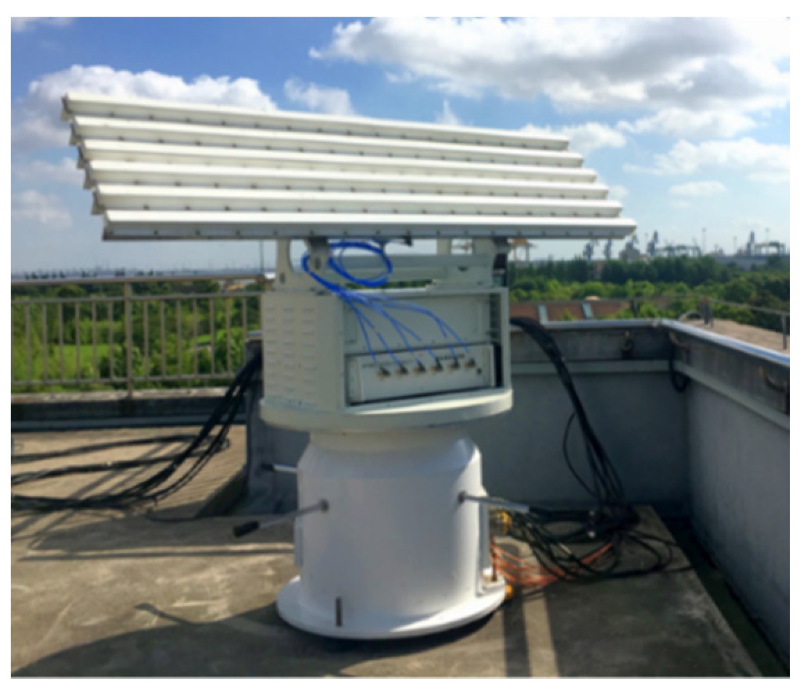
For this section, simulation and field experiment were conducted based on the MIMO radar system developed by the Beijing Institute of Technology (BIT) [6,7], which is shown in Figure 2. The ground-based radar operates at the S-band and has a co-located MIMO architecture. The antenna array is organized along the elevation axis with six elements transmitting st-MIMO waveforms. Each antenna has a wide beam of 90° in elevation, where the MIMO is formed, and a narrow beam of 3° in azimuth. For the azimuth, mechanical scanning is utilized to achieve full airspace coverage. The system is mainly focused on LSS target detection and tracking, such as that of small drones or birds. The st-MIMO-ICA method for ground clutter mitigation is first demonstrated with simulation results using parameters corresponding to a real radar system. Then, the field experiment results are presented.

4.1. Simulation Results

The simulations were conducted in MATLAB. They were employed to verify the performance of the proposed method. To reflect the performance of a real radar system used in the field, consider a co-located MIMO antenna array with M = N = 6 linear displaced elements along the elevation axis. Each element transmits a st-MIMO waveform. The simulated radar parameters are shown in Table 1.
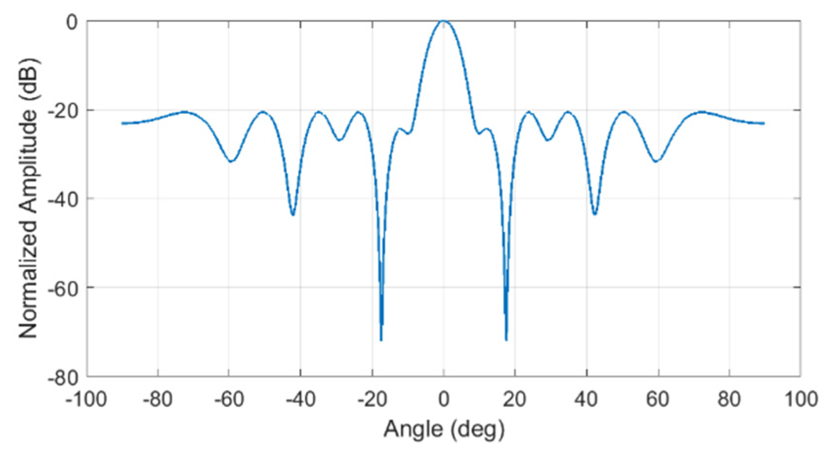
Furthermore, the antenna array was chosen to be a non-uniform sparse array to make it cost-effective with a larger aperture and fewer elements. The element location was optimized via a genetic algorithm (GA) to suppress the grating lobes of the antenna beampattern caused by the sparse arrangement. A detailed illustration and analysis of this non-uniform and sparse arrangement can be found in [6]. The array parameters are shown in Table 2, and the beam pattern of the array after GA optimization is shown in Figure 3.
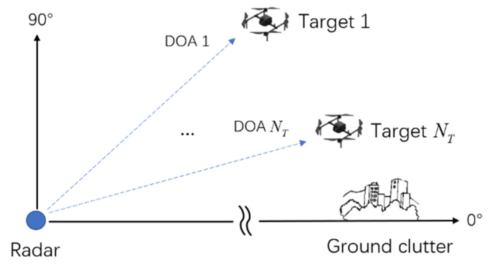
The simulation experiment setup is shown in Figure 4. The radar was ground-based, and the MIMO was achieved in elevation. The ground clutter came from the horizontal direction and Target 1 to Target N T had the target DOA 1 to DOA N T . A typical LSS target could be a small drone such as a DJI Phantom series drone. This type of target has a relatively slow speed and low flying altitude, which means the radar detection performance is affected by strong ground clutter. To simplify the simulation without losing generality, assume that there are three targets in the same range bin with different SNRs, speed, and DOAs. Regarding the ground clutter, we used the clutter model in Section 1 with four closely distributed DOAs to simulate a real ground environment containing trees and buildings of different heights. We set proper target SNRs to keep the target SCNRs of all the targets at −20 dB. Detailed parameters of the target and clutter setup are given in Table 3.
The results of signal modeling are shown in Figure 5. The range-velocity map of the received signal in antenna 1 after pulse-compression and PD processing is displayed in Figure 5a, from where the waveform diversity of st-MIMO has formed and the echoes from the six transmitting antenna, TX1 to TX6, have been shifted into different Doppler sub-bands. Moreover, the velocity spectrum at targets’ range bin is displayed in Figure 5b. where the black boxes indicate six Doppler sub-bands, DS1 to DS6. Together with the received signals in the other five antennas, all the Q = M × N = 36 transmitting-receiving paths, named as Channel 1 to Channel 36, can be established. The velocity spectrum of Channel 1 after MIMO demodulation is displayed in blue line in Figure 5c, and the red line represent the targets plus noise in order to indicate the targets information clearly. The CNR is 60 dB after pulse-compression and PD processing, and different target SNRs are set to keep the target SCNR as −20 dB.
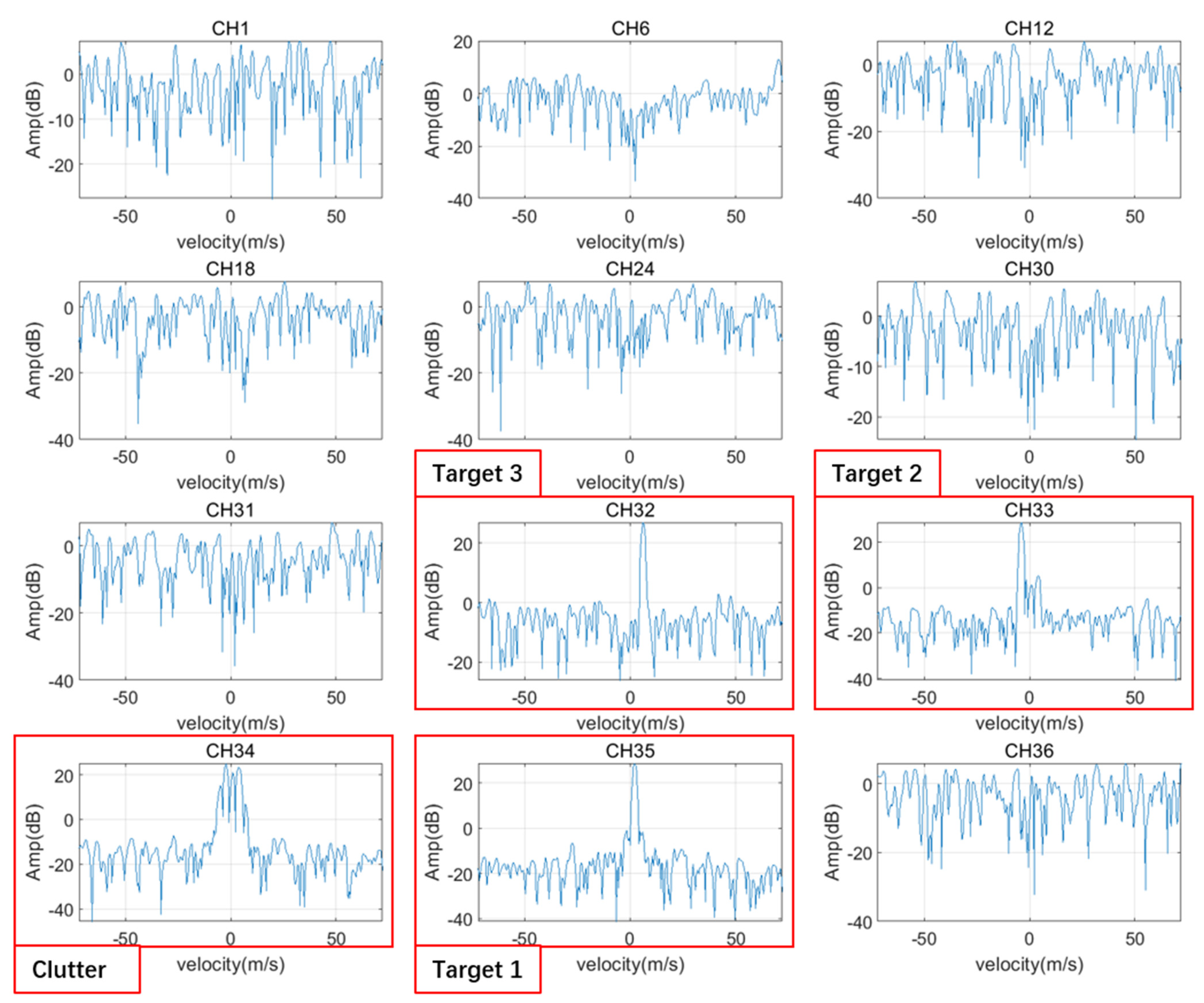
The st-MIMO-ICA output of the mixed signal is shown in Figure 6. Some representative results among all the 36 output channels are displayed. Excluding the uncertainty of the sequence of the output signals [22], the three targets are separated from the mixed targets plus clutter and noise signal and located in Channel 32, 33, and 35 respectively. Channel 34 contains the combination of the ground clutter. Because the clutter DOAs are closely distributed, the method fails to separate those clutter components. Lastly, the remaining channels are noise signals. Figure 7 shows the detailed information of the three separated targets after st-MIMO-ICA processing. All the three targets are precisely separated with correct velocity and desirable output SCNR of 29.8 dB, 23.4 dB, and 33.2 dB, respectively. We compare the results of st-MIMO-ICA with two other approaches which are also frequently utilized to mitigate the ground clutter, that is PCA and adaptive digital beamforming (ADBF). Among the ADBF approaches, the sample matrix inversion (SMI) technique is chosen. The results of these two approaches are also displayed in Figure 7, and it can be seen that the ICA method enjoys the highest target output SCNR. The exact target SCNR values of the three approaches are listed in Table 4.
Blind beamforming could be achieved using the weight matrix generated by the st-MIMO-ICA method. Figure 8 displays the beampatterns corresponding to the three targets, with w 32 , w 33 , and w 35 as the weight vectors. All the beampatterns could form a deep null in the clutter DOA, which effectively mitigated the strong ground clutter. Meanwhile, when the target DOA was close to the clutter DOA, the blind beamforming also suffered from distortion in the main beam and the loss of the target SCNR, which is shown in Figure 8a. Figure 8 also displays the equivalent beampatterns of PCA that were generated from the eigenvectors corresponding to the three targets and the adaptive beampatterns of SMI with the pre-known steering vectors pointing at the three targets. The st-MIMO-ICA method showed the deepest null level at the clutter’s DOA compared with the other two approaches, which illustrates the outplayed performance of the proposed method in ground clutter mitigation. The detailed null levels of the three approaches are also listed in Table 4.
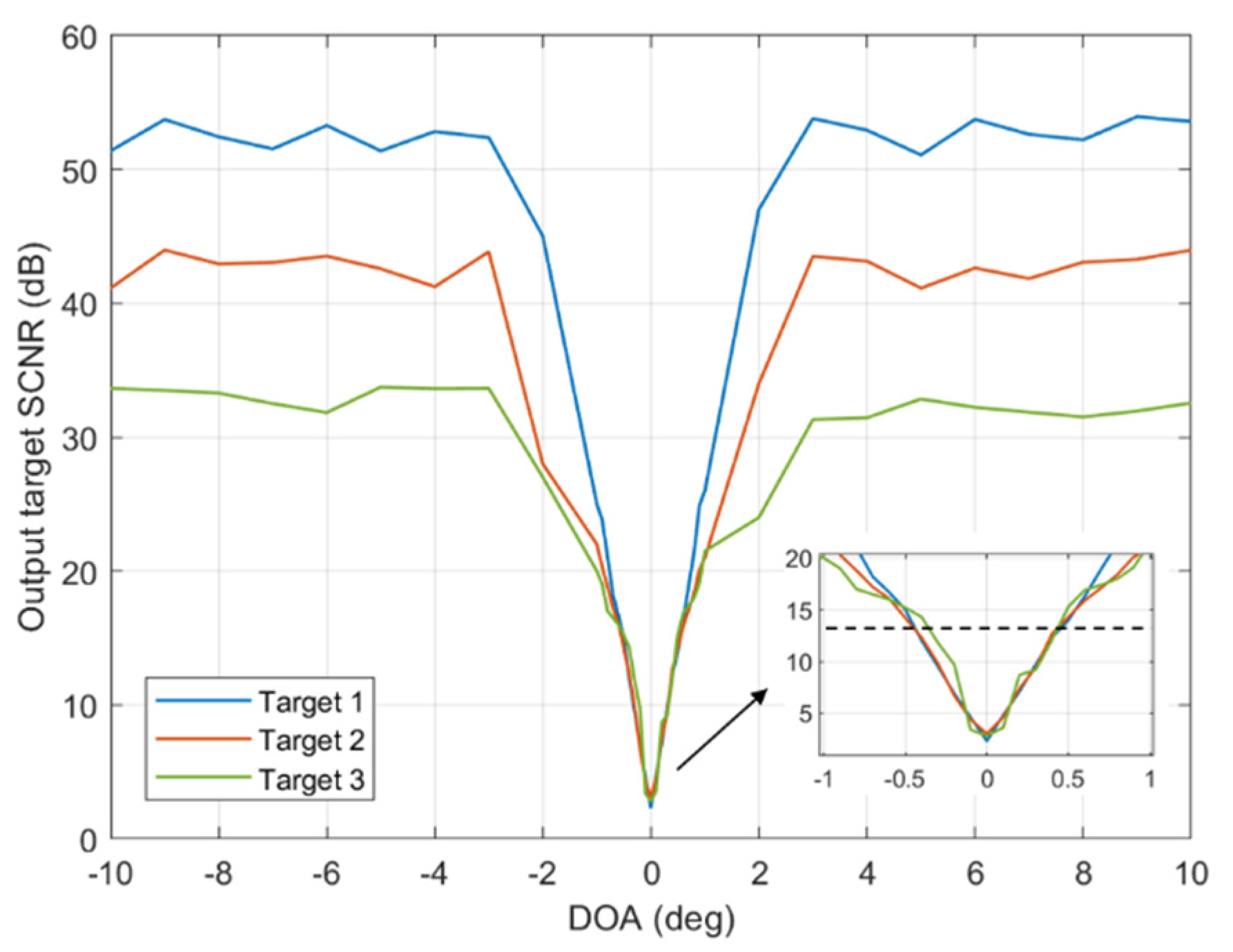
To investigate the performance boundary of the proposed st-MIMO-ICA method, a simulation of the output target SCNR under each target DOA was conducted, which is shown in Figure 9. We still focused on the three aforementioned targets: Target 1, Target 2, and Target 3. We let the DOA of the targets change from −10° to 10° while other parameters remained the same. To simplify the simulation, we also let the clutter DOA be 0°. The number of Monte Carlo simulations was chosen to be 100 for each target DOA. The output target SCNR well-corresponded to the input target SNR plus the coherent processing gain of the MIMO array, which was 15.5 dB ( Q = 36 ). However, when the target’s DOA was close to the clutter’s DOA, the output target SCNR was decreased due to the increase in the cross-correlation of the two components in the spatial domain. The black dashed line in the zoomed-out figure of Figure 9 indicates the sufficient detection threshold of 13 dB, and the corresponding target DOA was 0.4°, which was 6.5% of the MIMO beamwidth.

4.2. Field Experimental Results

Field experiments were conducted in a complex urban environment to verify the performance of the proposed method. The radar system is deployed in an industrial city in southeast China where factory buildings, trees, moving cars constitute the sources of the ground clutter. The satellite image of the radar location and surroundings courtesy of Google Maps is shown in Figure 10a, and the radar field of view is shown in Figure 10b. The parameters of the radar system were given in Table 1 and Table 2. The target information is listed in Table 5. A small drone of DJI Phantom IV is used as a real flying target in this section. The diagonal size of the small drone is 350mm and can be treated as a point target compared to the range resolution of the radar system. There are two range bins chosen as the field experiment location, which are 3041 m and 5585 m. The small drone has a flying altitude of 200 m at both locations, resulting in different target elevations of 3.8° and 2°, respectively.
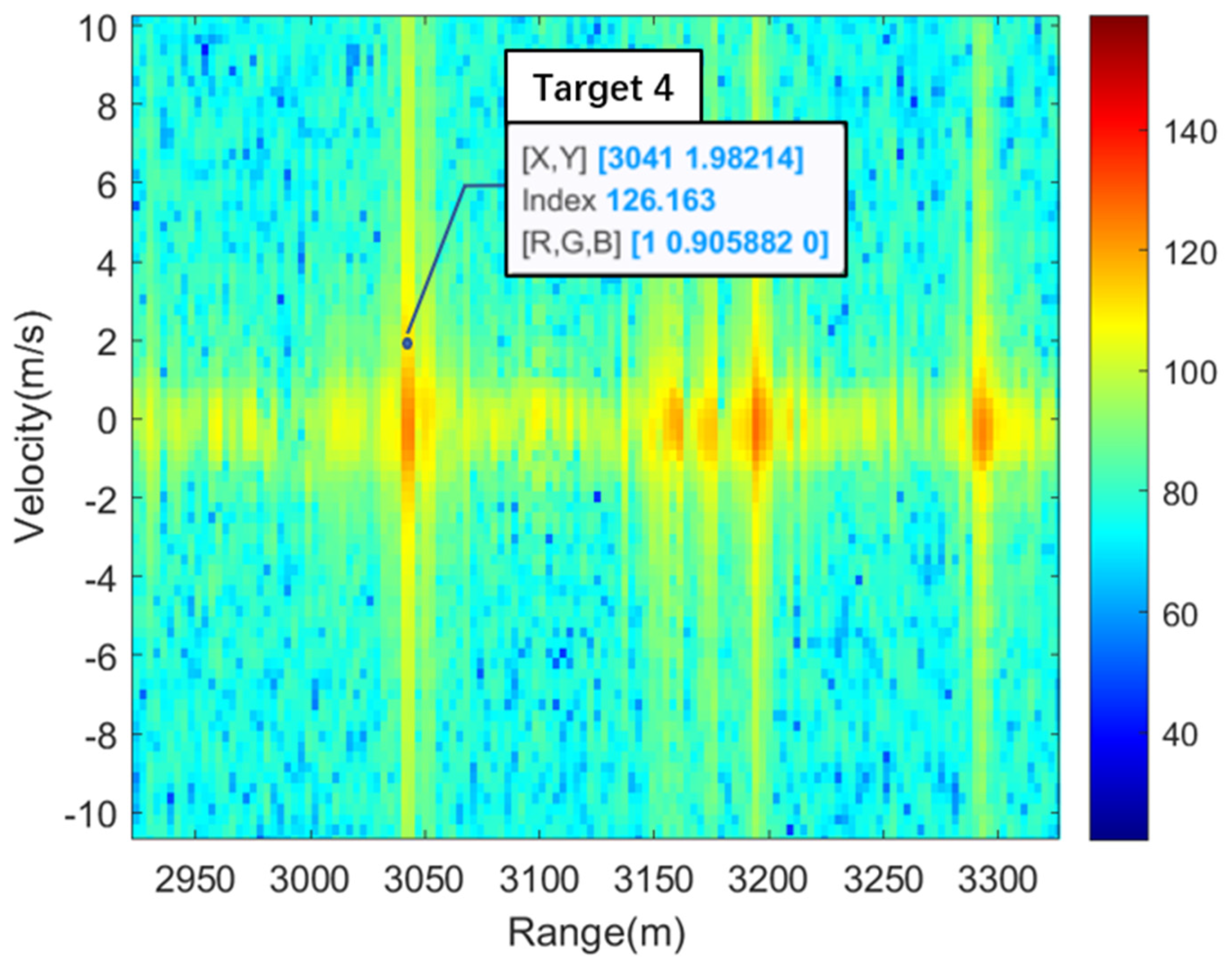
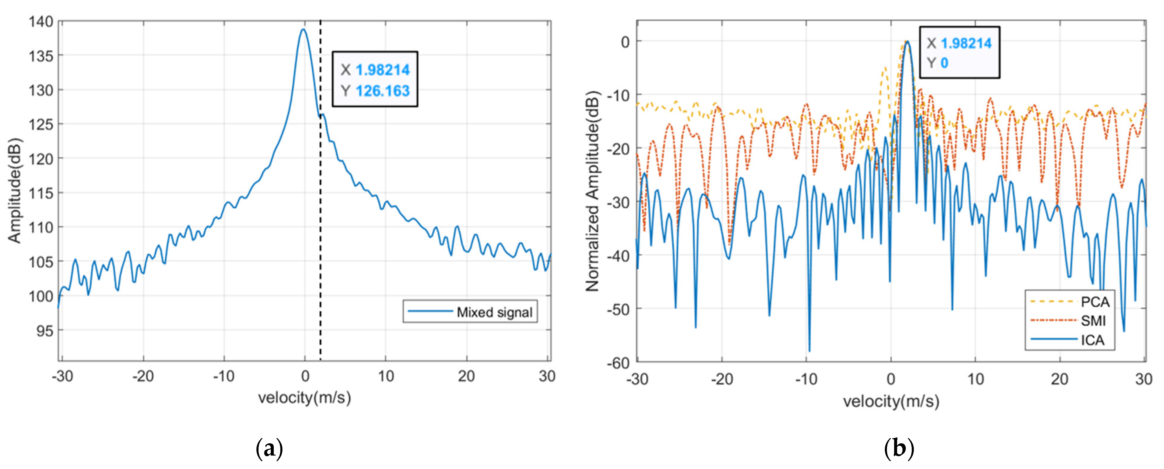
In the first experiment of 3041 m, the small drone has the speed of 2 m/s. The range-velocity map in Channel 1 after pulse-compression and PD processing is shown in Figure 11, where the data label indicates the target location, speed, and amplitude. The target is submerged in the spectrum of strong ground clutter and cannot be detected. The result of the st-MIMO-ICA processing of Target 4 is shown in Figure 12. The velocity spectrum at Target 4’s range bin before st-MIMO-ICA processing is shown in Figure 12a. The black dashed line indicates the target location in the mixed signal. The target is shadowed by strong ground clutter and cannot be detected via conventional method such as CFAR. The velocity spectrum after st-MIMO-ICA processing is shown in Figure 12b, where the target can be effectively extracted from the strong ground clutter with the highest output target SCNR of 33.9 dB. The other two approaches, PCA and SMI, are also conducted as a comparison with output target SCNR of 14.5 dB and 17.8dB, respectively. The output of the PCA approach also has a false alarm located at −1 m/s.
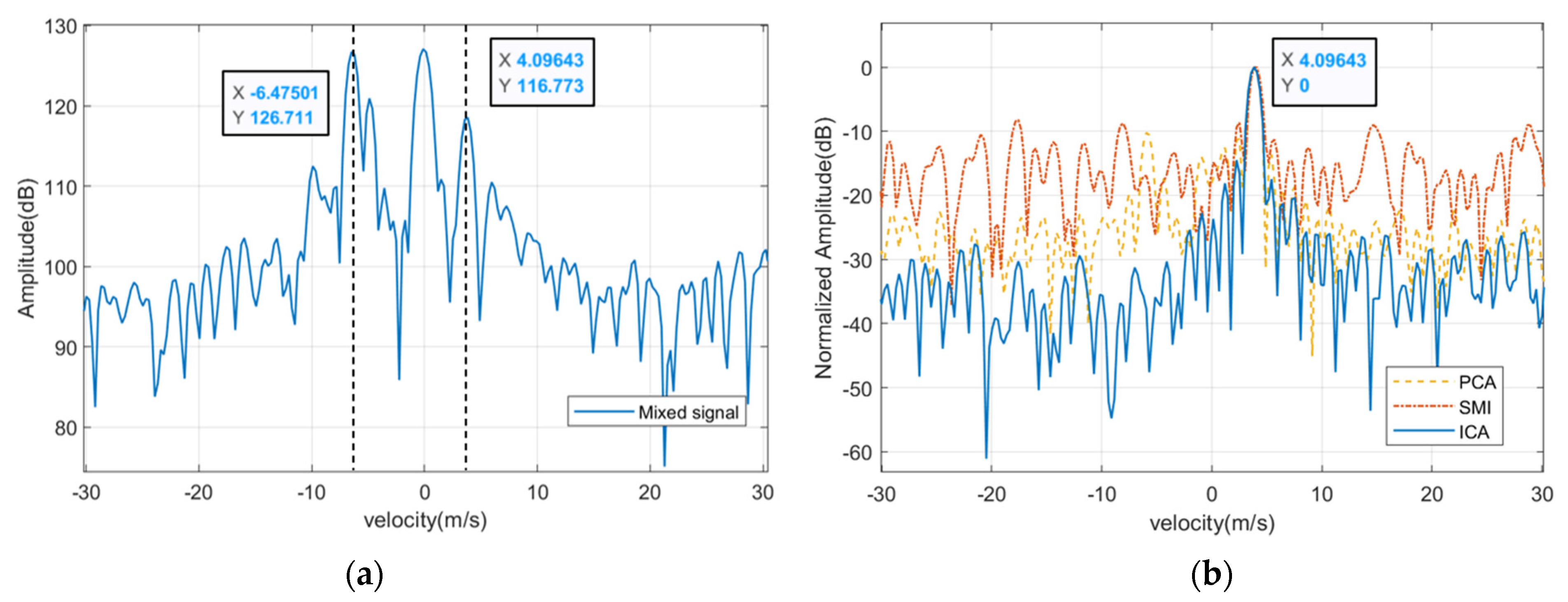
In the second experiment of 5585 m, the small drone has the speed of 4 m/s and can be seen in the range-velocity map together with some competing ground clutters which belong to the buildings and moving cars. The range-velocity map in Channel 1 after pulse-compression and PD processing is shown in Figure 13, where the data label indicates the target location, speed, and amplitude. The result of the st-MIMO-ICA processing of Target 5 is shown in Figure 14. The velocity spectrum at Target 5’s range bin before st-MIMO-ICA processing is shown in Figure 14a. The target had a SCNR of -10dB compared to the ground clutter located at 0 m/s and -6.5 m/s. The velocity spectrum after st-MIMO-ICA processing is shown in Figure 14b, where the target can be effectively extracted from the competing clutters with output target SCNR of 37.8 dB, and the other two remarkable ground clutters have been successfully suppressed. The results of PCA and SMI are also displayed with output target SCNR of 26.6 dB and 15.1dB, respectively. The output of the PCA approach also has a false alarm in the clutter location of −6.5 m/s.

5. Discussion

A ground clutter mitigation method for slow-time MIMO radar using independent component analysis was researched in this study. Firstly, a ground clutter model under a st-MIMO scheme was provided. The clutter covariance was derived based on a Gaussian-shaped power spectrum, and a universal signal modelling including the target, ground clutter, and noise was provided. Secondly, the compliance for conducting ICA was discussed, and the st-MIMO-ICA processing scheme was proposed. Lastly, the performance of the proposed method was verified with simulation and field experiments via an S-band MIMO radar system.
The simulation results indicated the feasibility of the proposed st-MIMO-ICA method, as the st-MIMO-ICA output showed the highest target SCNR compared with two other conventional clutter mitigation approaches of PCA and SMI. The three test targets with an input SCNR of −20 dB were precisely separated with the correct velocity and desirable output SCNRs of 29.8 dB, 23.4 dB, and 33.2 dB. The st-MIMO-ICA method also showed the deepest null level at the clutter’s DOA compared with the other two approaches. The performance boundary of the method as validated with a separable DOA difference of 6.5% of the MIMO beamwidth. The field experimental results further proved the effectiveness of the proposed method in LSS target detection with strong ground clutter compared with conventional methods.
It is worth noting that the PCA approach only utilizes the eigenvectors of the signal covariance matrix after conducting eigenvalue decomposition. As is noted in Section 1, PCA is often utilized as a preliminary step of ICA to decrease the dimensions of the data. Regarding the SMI technique, we chose to use target-plus-clutter-plus-noise signals in this study as the training data to calculate the adaptive weight vector, which limited the performance of the SMI technique. Generally, it is not feasible to obtain independent and identical distributed clutter samples in real scenes. The ICA method, however, utilizes negentropy as the cost function and the fixed-point algorithm for optimization to achieve better source separation results, which corresponds to desirable ground clutter mitigation performance.
There is still work to be conducted. It is worth further investigating the character of ground clutter, especially regarding the number of the sources of clutter. In this paper, we assumed that the DOAs of ground clutter for a certain snapshot were limited even though actual clutter characteristics are more complex. Another work will focus on the adaption of the detection threshold to further improve the detection performance for LSS targets [42,43].

Author Contributions

Conceptualization, F.Y. and Q.L.; methodology, F.Y.; software, F.Y.; validation, F.Y. and J.G.; formal analysis, F.Y. and R.Z.; investigation, F.Y. and J.G.; writing—original draft preparation, F.Y.; writing—review and editing, R.Z. and J.L.K.; visualization, F.Y. and J.L.K.; supervision, T.Z.; project administration, R.Z.; funding acquisition, Q.L. and T.Z. All authors have read and agreed to the published version of the manuscript.

Funding

This research was funded the National Key R&D Program of China (Grant No. 2018YFE0202101 and Grant No. 2018YFE0202103), the Natural Science Foundation of Chongqing, China (Grant No. 2020ZX3100039), and the National Natural Science Foundation of China (Grant No. 62201048).

Institutional Review Board Statement

Not applicable.

Informed Consent Statement

Not applicable.

Data Availability Statement

The data that support the findings of this study are available from the corresponding author, R.Z., upon reasonable request.

Acknowledgments

The authors would like to thank the editor and anonymous reviewers for their helpful comments and suggestions.

Conflicts of Interest

The authors declare no conflict of interest.

References

  1. Patel, J.; Fioranelli, F.; Anderson, D. Review of radar classification and RCS characterisation techniques for small UAVs or drones. IET Radar Sonar Navigat. 2018, 12, 911–919. [Google Scholar] [CrossRef]
  2. Zhao, C.; Luo, G.; Wang, Y.; Chen, C.; Wu, Z. UAV Recognition Based on Micro-Doppler Dynamic Attribute-Guided Augmentation Algorithm. Remote Sens. 2021, 13, 1205. [Google Scholar] [CrossRef]
  3. Raja Abdullah, R.S.A.; Alhaji Musa, S.; Abdul Rashid, N.E.; Sali, A.; Salah, A.A.; Ismail, A. Passive Forward-Scattering Radar Using Digital Video Broadcasting Satellite Signal for Drone Detection. Remote Sens. 2020, 12, 3075. [Google Scholar] [CrossRef]
  4. Aldowesh, A.; BinKhamis, T.; Alnuaim, T.; Alzogaiby, A. Low power digital array radar for drone detection and micro-Doppler classification. In Proceedings of the 2019 Signal Processing Symposium (SPSympo), Krakow, Poland, 17–19 September 2019; pp. 203–206. [Google Scholar]
  5. Aldowesh, A.; Alnuaim, T.; Alzogaiby, A. Slow-moving micro-UAV detection with a small scale digital array radar. In Proceedings of the 2019 IEEE Radar Conference (RadarConf), Boston, MA, USA, 22–26 April 2019; pp. 1–5. [Google Scholar]
  6. Yang, F.; Qu, K.; Hao, M.; Liu, Q.; Chen, X.; Xu, F. Practical investigation of a MIMO radar system for small drones detection. In Proceedings of the 2019 International Radar Conference (RADAR), Toulon, France, 23–27 September 2019; pp. 1–5. [Google Scholar]
  7. Yang, F.; Xu, F.; Fioranelli, F.; Le Kernec, J.; Chang, S.; Long, T. Practical investigation of a MIMO radar system capabilities for small drones detection. IET Radar Sonar Navigat. 2021, 15, 760–774. [Google Scholar] [CrossRef]
  8. Hao, M.; Yang, F.; Liu, Q. Slow-time MIMO radar waveform generator with experimental results. In Proceedings of the 2019 IEEE International Conference on Signal, Information and Data Processing (ICSIDP), Chongqing, China, 11–13 December 2019; pp. 1–5. [Google Scholar]
  9. Ritchie, M.; Fioranelli, F.; Griffiths, H.; Torvik, B. Monostatic and bistatic radar measurements of birds and micro-drone. In Proceedings of the 2016 IEEE Radar Conference (RadarConf), Philadelphia, PA, USA, 2–6 May 2016; pp. 1–5. [Google Scholar]
  10. Palamà, R.; Fioranelli, F.; Ritchie, M.; Inggs, M.; Lewis, S.; Griffiths, H. Measurements and discrimination of drones and birds with a multi-frequency multistatic radar system. IET Radar Sonar Navigat. 2021, 15, 841–852. [Google Scholar] [CrossRef]
  11. de Quevedo, Á.D.; Urzaiz, F.I.; Menoyo, J.G.; López, A.A. Drone detection and radar-cross-section measurements by RAD-DAR. IET Radar Sonar Navigat. 2019, 13, 1437–1447. [Google Scholar] [CrossRef]
  12. Jahangir, M.; Baker, C. Persistence surveillance of difficult to detect micro-drones with L-band 3-D holographic radar™. In Proceedings of the 2016 CIE International Conference on Radar (RADAR), Guangzhou, China, 10–13 October 2016; pp. 1–5. [Google Scholar]
  13. Jahangir, M.; Baker, C.J.; Oswald, G.A. Doppler characteristics of micro-drones with L-Band multibeam staring radar. In Proceedings of the 2017 IEEE Radar Conference (RadarConf), Seattle, WA, USA, 8–12 May 2017; pp. 1052–1057. [Google Scholar]
  14. Park, J.; Jung, D.-H.; Bae, K.-B.; Park, S.-O. Range-Doppler map improvement in FMCW radar for small moving drone detection using the stationary point concentration technique. IEEE Trans. Microw. Theory Technol. 2020, 68, 1858–1871. [Google Scholar] [CrossRef]
  15. Sun, H.; Oh, B.-S.; Guo, X.; Lin, Z. Improving the Doppler resolution of ground-based surveillance radar for drone detection. IEEE Trans. Aerosp. Electron. Syst. 2019, 55, 3667–3673. [Google Scholar] [CrossRef]
  16. Chen, X.; Guan, J.; Chen, W.; Zhang, L.; Yu, X. Sparse long-time coherent integration-based detection method for radar low-observable manoeuvring target. IET Radar Sonar Navigat. 2020, 14, 538–546. [Google Scholar] [CrossRef]
  17. Sun, Y.; Abeywickrama, S.; Jayasinghe, L.; Yuen, C.; Chen, J.; Zhang, M. Micro-Doppler signature-based detection, classification, and localization of small UAV with long short-term memory neural network. IEEE Trans. Geosci. Remote Sens. 2021, 59, 6285–6300. [Google Scholar] [CrossRef]
  18. Oh, B.-S.; Lin, Z. Extraction of global and local micro-Doppler signature features from FMCW radar returns for UAV detection. IEEE Trans. Aerosp. Electron. Syst. 2021, 57, 1351–1360. [Google Scholar] [CrossRef]
  19. Guo, J.; Chang, S.; Yang, F.; Cai, J.; Liu, Q.; Long, T. Low-slow-small target detection using stepped-frequency signals in a strong folded clutter environment. IET Radar Sonar Navigat. 2021, 15, 1030–1044. [Google Scholar] [CrossRef]
  20. Aircraft Birdstrike Avoidance Radar. Available online: https://detect-inc.com/aircraft-birdstrike-avoidance-radar (accessed on 1 September 2021).
  21. Smart, Affordable Drone Detection Radar. Available online: https://www.robinradar.com/iris-counter-drone-radar (accessed on 1 March 2020).
  22. Hyvärinen, A.; Karhunen, J.; Oja, E. Independent Component Analysis; John Wiley & Sons, Inc.: Hoboken, NJ, USA, 2001; pp. 151–154. [Google Scholar]
  23. Cardoso, J.-F. Blind signal separation: Statistical principles. Proc. IEEE Proc. 1998, 86, 2009–2025. [Google Scholar] [CrossRef] [Green Version]
  24. Cardoso, J.-F. Higher order contrast for independent component analysis. Neural Comput. 1999, 11, 157–193. [Google Scholar] [CrossRef]
  25. Cui, G.; Yu, X.; Carotenuto, V.; Kong, L. Space-Time Transmit Code and Receive Filter Design for Colocated MIMO Radar. IEEE Signal Process. 2017, 65, 1116–1129. [Google Scholar] [CrossRef]
  26. Yu, X.; Cui, G.; Yang, J.; Kong, L. MIMO Radar Transmit–Receive Design for Moving Target Detection in Signal-Dependent Clutter. IEEE Trans. Veh. Technol. 2020, 69, 522–536. [Google Scholar] [CrossRef]
  27. Cheng, Z.; He, Z.; Liao, B.; Fang, M. MIMO Radar Waveform Design With PAPR and Similarity Constraints. IEEE Signal Process. 2018, 66, 968–981. [Google Scholar] [CrossRef]
  28. Mecca, V.F.; Ramakrishnan, D.; Krolik, J.L. MIMO radar space-time adaptive processing for multipath clutter mitigation. In Proceedings of the Fourth IEEE Workshop on Sensor Array and Multichannel Processing, Waltham, MA, USA, 12–14 July 2006; pp. 249–253. [Google Scholar]
  29. Bliss, D.W.; Forsythe, K.W.; Davis, S.K.; Fawcett, G.S.; Rabideau, D.J.; Horowitz, L.L.; Kraut, S. GMTI MIMO radar. In Proceedings of the 2009 International Waveform Diversity and Design Conference, Kissimmee, FL, USA, 8–13 February 2009; pp. 118–122. [Google Scholar]
  30. Li, J.; Stoica, P. MIMO Radar Signal Processing; John Wiley & Sons, Inc.: Hoboken, NJ, USA, 2009; pp. 293–297. [Google Scholar]
  31. Mecca, V.F.; Krolik, J.L. Slow-time MIMO STAP with improved power efficiency. In Proceedings of the 2007 Conference Record of the Forty-First Asilomar Conference on Signals, Systems and Computers, Pacific Grove, CA, USA, 4–7 November 2007; pp. 202–206. [Google Scholar]
  32. Mecca, V.F.; Krolik, J.L.; Robey, F.C. Beamspace slow-time MIMO radar for multipath clutter mitigation. In Proceedings of the 2008 IEEE International Conference on Acoustics, Speech and Signal Processing, Las Vegas, NV, USA, 31 March–4 April 2008; pp. 2313–2316. [Google Scholar]
  33. Zhu, L.; Zhang, S.; Ma, Q.; Zhao, H.; Chen, S.; Wei, D. Classification of UAV-to-ground targets based on enhanced micro-Doppler features extracted via PCA and compressed sensing. IEEE Sens. J. 2020, 20, 14360–14368. [Google Scholar] [CrossRef]
  34. Dou, D.; Li, M.; He, Z. Multi-mode clutter suppression of multiple-input–multiple-output over-the-horizon radar based on blind source separation. IET Radar Sonar Navigat. 2015, 9, 956–966. [Google Scholar] [CrossRef]
  35. Yu, W.; Chen, J.; Bao, Z. Multi-mode propagation mode localisation and spread-Doppler clutter suppression method for multiple-input multiple-output over-the-horizon radar. IET Radar Sonar Navigat. 2019, 13, 1214–1224. [Google Scholar] [CrossRef]
  36. Ge, M.; Cui, G.; Yu, X.; Kong, L. Main lobe jamming suppression via blind source separation sparse signal recovery with subarray configuration. IET Radar Sonar Navig. 2020, 14, 431–438. [Google Scholar] [CrossRef]
  37. Robey, F.C.; Coutts, S.; Weikle, D.; McHarg, J.C.; Cuomo, K. MIMO radar theory and experimental results. In Proceedings of the Thirty-Eighth Asilomar Conference on Signals, Systems and Computers, Pacific Grove, CA, USA, 7–10 November 2004; pp. 300–304. [Google Scholar]
  38. Wen, C.; Huang, Y.; Peng, J.; Wu, J.; Zheng, G.; Zhang, Y. Slow-time FDA-MIMO technique with application to STAP radar. IEEE Trans. Aerosp. Electron. Syst. 2022, 58, 74–95. [Google Scholar] [CrossRef]
  39. Xu, J.; Peng, Y.; Wan, Q.; Wang, X.; Xia, X. Doppler distributed clutter model of airborne radar and its parameters estimation. Sci. China Inf. Sci. 2004, 47, 577–586. [Google Scholar] [CrossRef]
  40. Hyvärinen, A.; Oja, E. Independent component analysis: Algorithms and applications. Neural Netw. 2000, 13, 411–430. [Google Scholar] [CrossRef] [PubMed] [Green Version]
  41. Novey, M.; Adali, T. On extending the complex FastICA algorithm to noncircular sources. IEEE Trans. Signal Process. 2008, 56, 2148–2154. [Google Scholar] [CrossRef]
  42. Zhang, H.; Liu, W.; Shi, J.; Fei, J.; Zong, B. Joint detection threshold optimization and illumination time allocation strategy for cognitive tracking in a networked radar system. IEEE Trans. Signal Process. 2008; early access. [Google Scholar]
  43. Yan, J.; Pu, W.; Zhou, S.; Liu, H.; Bao, Z. Collaborative detection and power allocation framework for target tracking in multiple radar system. Inf. Fusion 2020, 55, 173–183. [Google Scholar] [CrossRef]
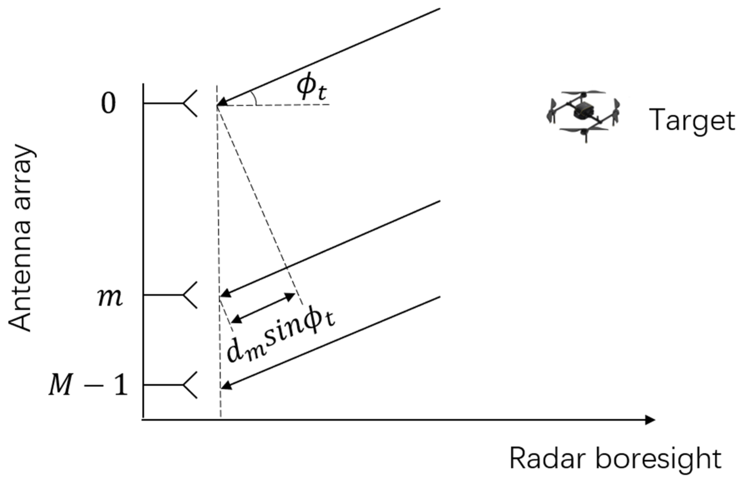
Figure 1. The geometry of signal modeling.
Remotesensing 14 06098 g001
Figure 2. The ground-based MIMO radar system for LSS target detection.
Remotesensing 14 06098 g002
Figure 3. Array beam pattern after GA optimization. The 3 dB beamwidth is 6.2° and the side lobes are all below −20 dB without a gating lobe.
Remotesensing 14 06098 g003
Figure 4. The experimental setup for the simulation.
Remotesensing 14 06098 g004
Figure 5. Results of signal modeling: (a) Range–velocity map of the received signal in antenna 1 after PD processing, where waveform diversity was formed via st-MIMO; (b) velocity spectrum at targets’ range bin in antenna 1, where six Doppler sub-bands (DS1-DS6) were established and echoes from the six transmitting antenna (Tx1–Tx6) can be seen; (c) velocity spectrum of Channel 1 after MIMO demodulation, where three targets can be seen in the red line of targets plus noise.
Remotesensing 14 06098 g005
Figure 6. The st−MIMO−ICA output of the mixed signal, where the three targets were separated and were located in Channels 32, 33, and 35; Channel 34 was the ground clutter combination, and the other channels contained noise signals.
Remotesensing 14 06098 g006
Figure 7. The three separated targets after st−MIMO−ICA processing together with the results of the other two approaches: (a) Target 1′s velocity spectrum; (b) Target 2′s velocity spectrum; (c) Target 3′s velocity spectrum.
Remotesensing 14 06098 g007
Figure 8. The ICA beampatterns corresponding to the three targets together with the equivalent beampatterns of PCA and the adaptive beampatterns of SMI; the DOAs of the targets and clutter are displayed with black dashed lines, Dc, D1, D2, and D3 represent the DOAs of the clutter, Target 1, Target 2, and Target 3, respectively: (a) Target 1′s beampattern; (b) Target 2′s beampattern; (c) Target 3′s beampattern.
Remotesensing 14 06098 g008
Figure 9. The output target SCNR as a function of DOA with Target 1, Target 2, and Target 3; the black dashed line indicates the normal detection threshold of 13 dB.
Remotesensing 14 06098 g009
Figure 10. Field experiment scene: (a) the satellite image of the radar location and surroundings (courtesy of Google Maps); (b) the actual view from the radar.
Remotesensing 14 06098 g010
Figure 11. The range−velocity map in Channel 1 for the first field experiment. Target 4′s information is indicated via a data label; the target was submerged in strong ground clutter.
Remotesensing 14 06098 g011
Figure 12. The st−MIMO−ICA result of Target 4: (a) velocity spectrum at Target 4′s range bin before st−MIMO−ICA processing, where the target was submerged in strong ground clutter; (b) velocity spectrum comparison.
Remotesensing 14 06098 g012
Figure 13. The range−velocity map in Channel 1 for the second field experiment. Target 5′s information is indicated via a data label, and the target can be seen together with some competing ground clutter.
Remotesensing 14 06098 g013
Figure 14. The st−MIMO−ICA result of Target 5: (a) velocity spectrum at Target 5′s range bin before st−MIMO−ICA processing, where some competing ground clutter can be seen; (b) velocity spectrum comparison.
Remotesensing 14 06098 g014
Table 1. Radar parameters.
ParameterValue
Operating frequency3 GHz
Bandwidth40 MHz
Pulse repetition interval56 us
Number of pulses in one CPI900
Number of Doppler sub-band6
Maximum detect range8.4 km
Velocity measurement range±72 m/s
Table 2. Array parameters.
ParameterValue
Number of antenna6
Number of channels36
Array aperture0.5 m
Virtual array aperture1 m
Element position[0 0.1821 0.2681 0.3555 0.4206 0.5] m
Peak sidelobe level−20 dB
3 dB beamwidth6.2°
Table 3. Target and clutter parameters.
TypeParameterValue
Target 1Range500 m
Speed2 m/s
Elevation
SNR40 dB
SCNR−20 dB
Target 2Range500 m
Speed−4 m/s
Elevation20°
SNR30 dB
SCNR−20 dB
Target 3Range500 m
Speed6 m/s
Elevation10°
SNR20 dB
SCNR−20 dB
Ground clutterSpectrum center0 m/s
3 dB Spectrum width±2 m/s
DOAs[0° 0.1° 0.2° 0.3°]
CNR60 dB
Table 4. Comparison of simulation results.
Results (dB)Target 1Target 2Target 3
PCASCNR2.785.6815.17
Null level−28.10−34.82−53.20
SMISCNR11.7913.2423.82
Null level−34.27−44.87−59.90
ICASCNR29.7723.4233.20
Null level−52.97−49.97−75.46
Table 5. Target parameters in field test.
TypeParameterValue
Target 4Range3041 m
Speed2 m/s
Height200 m
Elevation3.8°
Target 5Range5585 m
Speed4 m/s
Height200 m
Elevation
Publisher’s Note: MDPI stays neutral with regard to jurisdictional claims in published maps and institutional affiliations.