Article

Aerial Image Dehazing Using Reinforcement Learning

Institute of Remote Sensing Satellite, China Academy of Space Technology, Beijing 100094, China
*
Author to whom correspondence should be addressed.
Remote Sens. 2022, 14(23), 5998; https://doi.org/10.3390/rs14235998
Submission received: 17 October 2022 / Revised: 13 November 2022 / Accepted: 18 November 2022 / Published: 26 November 2022
(This article belongs to the Special Issue Deep Reinforcement Learning in Remote Sensing Image Processing)

Abstract

:
Aerial observation is usually affected by the Earth’s atmosphere, especially when haze exists. Deep reinforcement learning was used in this study for dehazing. We first developed a clear–hazy aerial image dataset addressing various types of ground; we then compared the dehazing results of some state-of-the-art methods, including the classic dark channel prior, color attenuation prior, non-local image dehazing, multi-scale convolutional neural networks, DehazeNet, and all-in-one dehazing network. We extended the most suitable method, DehazeNet, to a multi-scale form and added it into a multi-agent deep reinforcement learning network called DRL_Dehaze. DRL_Dehaze was tested on several ground types and in situations with multiple haze scales. The results show that each pixel agent can automatically select the most suitable method in multi-scale haze situations and can produce a good dehazing result. Different ground scenes may best be processed using different steps.

1. Introduction

In recent years, aerial Earth observation technology has rapidly developed, with increasingly higher resolutions and better image quality being produced by researchers. The applications of aerial images include target detection and recognition, land-object classification, and change detection. However, for long-distance aerial observations, the image acquisition process is affected by the Earth’s atmosphere. The scattering and absorption of solar radiation and ground-reflected light by the atmosphere, haze, and clouds reduce the clarity and contrast of aerial images, and thus affect their application. Atmospheric influences are generally removed from aerial images using the following methods [1,2]: dehazing methods based on image and graphics processing, or atmospheric corrections based on radiative transfer calculations [3,4,5]. The advantages of image- and graphics-based methods are that they do not require additional information, are simple, and can considerably improve the effect of subsequent non-quantitative applications. The advantage of the radiative transfer calculation-based method is that it can accurately and quantitatively invert the ground-surface reflectance for subsequent quantitative applications. However, atmospheric parameter information at the time of imaging is required, and the calculation of the atmospheric radiative transfer process is complex and time-consuming. In the current paper, a method based on image and graphics processing is used to conduct research on the dehazing of aerial images.
Scholars have developed a series of methods for dehazing based on image and graphics processing, such as the classic dark channel prior (DCP) [6]; color attenuation prior (CAP) [7]; non-local image dehazing (NLD) [8]; and deep learning network methods, such as multi-scale convolutional neural networks (MSCNNs) [9], DehazeNet [10], and the all-in-one dehazing network (AODNet) [11]. However, these methods all focus on dehazing natural-ground images. There are considerable differences in the effects of haze in natural ground and aerial images, namely:
(1) The atmospheric transmittance function of natural-ground images is related to the distance (depth) of the image and has a strong correlation with the edge of the object in the image. By contrast, the atmospheric transmittance function of aerial images is only related to the characteristics of the atmosphere. Because of the high altitude of the imaging aircraft, the imaging distance of ground objects with different elevations is almost the same.
(2) As for aerial images, clouds may exist on the imaging path. Generally, images obtained through thin clouds can be recovered, but the recovery is not as likely if thick clouds exist.
  • The contributions of the current study are as follows:
  • We develop a specialized clear–hazy image dataset for aerial images.
  • We compare the different dehazing method effects on aerial images.
  • We are the first to explore the application of deep reinforcement learning (DRL) to image dehazing, and we achieve good results.
  • According to the differences between the natural-ground and aerial images, we select the most suitable dehazing method, which is modified to a multi-scale form, to use in the DRL method. Then, every pixel of the hazy image independently selects its best solution using the decision-making abilities of the DRL method. The choices in the DRL process can be displayed visually, and we can observe the actions of each pixel in each step of the process of obtaining the final result, which is convenient for analyzing the results.
In the remainder of this article, Section 2 introduces the existing dehazing algorithms and the use of DRL methods in the field of image processing; Section 3 presents the datasets used in this study; Section 4 introduces our dehazing method; Section 5 presents the dehazing results obtained using our method and discusses them; and finally, Section 6 presents the paper’s conclusion.

2. Related Work

2.1. Dehazing Algorithms

The haze physical model can be described as follows [12]:
I ( x ) = J ( x ) t ( x ) + A ( 1 t ( x ) ) ,
where x represents the position in the image; I ( x ) represents the hazy image value at position x obtained by the camera device; J ( x ) represents the clear image at position x obtained when there are no atmosphere effects; t ( x ) represents the atmosphere transmission map; and A represents the atmospheric background light intensity.
Using the Beer–Lambert law theorem, t ( x ) can be expressed as follows:
t ( x ) = e β ( λ , x ) d ( x ) ,
where β is the extinction coefficient of the atmosphere and d is the distance between the photographed target and the camera, that is, the depth of the image.
The process of image dehazing is knowing I ( x ) and deriving J ( x ) . In Equations (1) and (2), to obtain J ( x ) , A and t ( x ) first need to be obtained. Scholars have developed many algorithms to estimate J ( x ) from I ( x ) , the core of which is to estimate A and t ( x ) from some prior knowledge and then obtain J ( x ) .
Tan [13] developed a cost function using the framework of Markov random fields and relying on the following two basic observations: first, the haze-free image must have a higher contrast than the input haze image; second, variation in the airlight mainly depends on the distance of objects to the viewer. Fattal [14] estimated the transmission in hazy scenes relying on the assumption that the transmission and surface shading were locally uncorrelated. This approach is physically sound, but it solves a non-linear inverse problem, and therefore its performance greatly depends on the quality of the input data. Zhu et al. [7] proposed a linear color-attenuation prior method based on the difference between the brightness and saturation of the pixels of the hazy image. The scene radiance of the hazy image can be recovered using this method. Berman et al. [8] noted that in a hazy image, tight color clusters change because of haze and form lines in the RGB space that pass through the airlight coordinates. An algorithm was proposed to identify these haze lines, and the transmission of each pixel was estimated. However, this method may fail for scenes where the airlight is significantly brighter than the scene. He et al. [6] proposed a simple haze-removal method based on the key observation that most local patches in haze-free outdoor images contain some pixels that have very low intensities in at least one color channel. The DCP performs well, but when the scene objects are inherently similar to the atmospheric light and no shadow has been cast on them, the dark channel prior may be invalid. Cai et al. [10] proposed a trainable end-to-end system called DehazeNet for a medium-transmission estimation. DehazeNet adopts a convolutional neural network (CNN)-based deep architecture and a novel non-linear activation function bilateral rectified linear unit (BReLU). Ren et al. [9] presented a multiscale deep neural network called MSCNN by learning the mapping between hazy images and their corresponding transmission maps. It consists of a coarse-scale net that predicts a holistic transmission map based on the entire image, and a fine-scale net that locally refines the results.
There are also end-to-end methods such as AOD-Net that directly learn clear-image features obtained from hazy images, and then acquire the clear image. Li et al. [11] proposed AOD-Net, which directly generates the clean image using a lightweight CNN.

2.2. Application of DRL in the Field of Image Processing

DRL is a combination of deep learning and reinforcement learning (RL) techniques. It integrates the powerful understanding ability of deep learning in perception problems such as vision with the decision-making ability of RL. Since the emergence of DRL, it has been widely used in applications that require decision-making and control, typically in the fields of games and machine control, such as StarCraft, Atari games, Go, chess, autonomous driving systems/unmanned vehicles, and robot control.
Recently, studies have emerged that apply DRL to image processing functions. There are studies that use DRL for object detection [15,16,17,18] as well as image segmentation and classification [19,20]. DRL is also used for semi-supervised hyperspectral band selection and hyperspectral image classification [21,22], including hyperspectral unmixing [23]. Moreover, some studies use DRL to obtain image super-resolution [24,25,26]. DRL is also used to automatically extract road networks from remote-sensing images.
Furuta developed a network called pixelRL that is used for pixel-wise manipulations [27]. PixelRL is a multi-agent RL method, where each pixel has an agent. Each pixel value is regarded as the current state and is iteratively updated by the agent’s action. This method is used for image denoising, restoration, and color enhancement [28]. PixelRL has also been adopted for magnetic resonance imaging reconstruction [29], 3D medical image segmentation [30], image-instance segmentation [31], and single-image super-resolution [26].

3. Datasets

A large number of real hazy aerial images and their haze-free counterparts are usually difficult to collect; hence, synthesizing the images is a more realistic method.
We developed an aerial hazy–clear pair dataset that contains various ground types, including residential, city, farmland, and forest areas. To date, this is the first dataset that focuses on aerial image dehazing. The previous datasets are mostly ground indoor- and outdoor-scene images. As previously mentioned, considerable differences exist between ground and aerial images. It was therefore necessary to develop a specialized dataset.
The INRIA Aerial Image Labeling dataset was used to develop the dataset. This dataset presents aerial orthorectified color imagery with a spatial resolution of 0.3 m, covering an area of 810 km² (405 km² for training and 405 km² for testing). As a result of the longer path along which the ground signal must propagate prior to being imaged, the satellite images are affected more than the aerial images. We hence selected aerial images for the following work.
We selected eight clear images from the INRIA Aerial Image Labeling dataset to create the dataset. These eight clear images represented four typical scenes: residential, city, farmland, and forest areas. For each scene, two images from INRIA were selected. Typical scenes are shown in Figure 1.
The size of each image was 5000 × 5000, and the images were divided into many 70 × 70 images. Then, for each 70 × 70 image block, we randomly selected transmissions in the range (0.2, 0.9) to generate the hazy images. Thus, 40,328 hazy images and the corresponding clear images were created. For validation, 4032 of the images were selected, and the remainder were used for training. For testing, eight group images which were independent of the above 40,328 images were used. There were 250 images in each group. These eight group images also represented the four typical scenes, with two groups for each scene.
In a large-scale aerial image, the distribution patterns of haze or thin cloud can have various scales and forms, which affect the image in patches with different sizes. The atmosphere transmittance in a particular patch is generally uniform or changes slowly, and changes greatly at its boundary. We constructed the transmissions with various patch sizes to simulate the scene described above.
According to the haze features of aerial images, we developed a multi-scale haze-image dataset, as presented in Figure 2. Three kinds of scale size were developed: they were uniform-haze, medium-scale, and small-scale situation.

4. Methods

Image dehazing is a problem that involves the selection of the dehazing method, and the best dehazing method or parameters may be different for different pixels of the image. Hence, the dehazing process is a decision process for each pixel in the image. A pixel-based RL method is suitable for this problem. We used a pixel-level DRL method based on pixelRL to solve the dehazing problem, and we call this method DRL_Dehaze.

4.1. Problem Formulation

We formulated the aerial image dehazing problem as a Markov decision process (MDP) problem that can be described by s , a , r , P , λ . Here, s represents the state, a represents the action that is chosen based on policy π , r represent the reward, P is the transfer probability, and λ is the discount factor for the cumulative reward.
In the dehazing problem, every pixel can be treated as an agent. The input image is a hazy image, and the agent performs actions to remove the haze iteratively. State s i ( t ) is simply the i-th pixel value at time step t . The agent selects action a i ( t ) from action set a i ( t ) A according to policy π i ( a i ( t ) | s i ( t ) ) , where A is the action set pre-defined by the author. We designed the action set by comparing state-of-the-art dehazing methods and choosing the most suitable ones. The agent changes to the next state s i ( t + 1 ) and achieves a reward r i ( t ) by taking action a i ( t ) . An action a i ( t ) changes the pixel value s i ( t ) to s i ( t + 1 ) , and s i ( t + 1 ) is the dehazing result of the i-th pixel using one of the methods in the action set A .

4.2. PixelRL Method

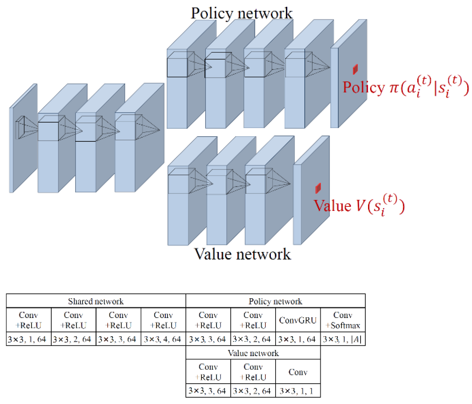
In the pixelRL method, an asynchronous advantage actor–critic (A3C) algorithm [32] was used to solve the problem. The A3C algorithm was a type of actor–critic method, which was a combination of value function- and policy-centric algorithms. It mainly consisted of two networks: policy and value networks. The policy network outputted actions based on probabilities, and the value network calculated the expected total rewards of the state. The policy network updated the probabilities of the actions according to the critic obtained from the value network. The pixelRL network architecture is presented in Figure 3. The objective of pixelRL is to learn the best policies π i ( a i ( t ) | s i ( t ) ) for each pixel. However, a traditional multi-agent RL method is not suitable for this problem, because the number N of image pixels is normally very large. The pixelRL method is different from a typical multi-agent RL problem for the following reasons:
1.
Fully convolutional networks (FCN) were used instead of N networks; hence, all N agents can share the parameters. The A3C was modified to a fully convolutional form, as illustrated in Figure 3.
2.
The network was designed with a bigger receptive field to boost the network performance. The policy and value networks not only observe the i-th pixel but also the neighbor pixels. In this case, action a i ( t ) affects not only state s i ( t + 1 ) , but also the policies and values in a local window centered at the i-th pixel. The selected action not only affects the i-th pixel, but also the pixels in the local window centered at the i-th pixel.

4.3. Actions

The action set was defined by the author. The choice of method was realized by choosing pixel values obtained from dehazed images processed by different methods. The methods can be any dehazing method. The objective of pixelRL was to obtain the optimal policy for every pixel.
The DRL action set design should be suitable for our aerial image-dehazing problem. We tested state-of-the-art dehazing methods, including DCP, CAP, NLD, DehazeNet, AODNet, and MSCNN. All the models were trained to convergence using the dataset described in Section 3, followed by image prediction.
We selected two indicators to quantitatively evaluate the dehazing performance of the methods: the peak signal-to-noise ratio (PSNR) and structural similarity index measure (SSIM).
The PSNR of the image was calculated based on the error between the corresponding pixels of the predicted and ground-truth images. A higher PSNR indicated a smaller difference between the predicted and true images.
P S N R = 10 l o g 10 ( Q 2 M S E )
where Q is the image pixel gray level, which we set to 255; and MSE is the mean squared difference between the predicted and true haze-free images.
M S E = 1 M × N i = 1 M j = 1 N ( f ( i , j ) - f ( i , j ) ) 2 ,
where f ( i , j ) and f ( i , j ) represent the predicted and ground-truth images, respectively; and M and N represent the length and width of the image, respectively.
SSIM measured the similarity between the two images. The SSIM of two images can range from 0 to 1. When the two images were identical, the value of SSIM was equal to 1.
S S I M = ( 2 μ x μ y + c 1 ) ( σ x y + c 2 ) ( μ x 2 + μ y 2 + c 1 ) ( σ x 2 + σ y 2 + c 2 )
where μ x is the average gray level of the predicted image, μ y is the average gray value of the true image, σ x is the gray value standard deviation of the predicted image, σ y is the gray value standard deviation of the true image, and σ x y is the gray value covariance of the two images. In addition, c 1 = ( K 1 L ) 2 , c 2 = ( K 2 L ) 2 are constants to keep the denominator from being zero, where K 1 = 0.01 , K 2 = 0.03 , and L , are the dynamic range of the pixel values.
Table 1 lists the quantitative evaluation results of the traditional methods on hazy images and the dehaze results. In Table 1, the bold font indicates the best method. The testing dataset was labeled with R1, R2, C1, C2, FO1, FO2, FA1, and FA2. R1, R2 represent the two residential area image groups; C1, C2 represent the two city area image groups, FO1, FO2 represent the two forest area image groups; FA1, FA2 represent the two farmland area groups.
The PSNR and SSIM indicators of the hazy image were closely related with the atmosphere transmission. A bigger atmosphere transmission meant less difference between the clear and hazy image; therefore, the PSNR and SSIM would be better.
DCP, CAP, and NLD had a poor performance on aircraft images. In some cases when the atmosphere hazy effect was relatively small, the dehazed image using DCP, CAP, and NLD was even worse than the hazy image. The learning methods such as DehazeNet, AODNet, or MSCNN were much better.
The principles of DCP, CAP, NLD, and other methods are based on the experience of natural-ground image dehazing, and the influence of haze is inferred based on the image and some prior knowledge. These methods have a strong correlation with the structure and brightness of the objects in the image. It can be observed from the transmission map inferred from the dehazing results that the edges of the objects in the image are also the inflection points of the transmission map. This is related to the principles of the DCP, CAP, and NLD methods. This causes the image to produce a modulation transfer function compensation (MTFC) effect, and the edge of the object appears clearer, especially when the grayscale of the object is quite different from the grayscale of the surrounding environment. The DCP method may overcorrect the dark gray ground objects. Both the CAP and NLD methods present similar problems caused by the structure of the transmission map. The DehazeNet, AODnet, and MSCNN methods that learned from the database produce better results on the aerial images.
However, for forests, where the structural feature is not obvious and is relatively uniform, the above-mentioned structural influences of the transmission map had little effect on the dehazing results. Methods such as DCP, CAP, and NLD, were less different than the other methods.
The DehazeNet method obtains the best results for aerial images when compared with the other methods. In an aerial image, because the haze may affect the image at different scales, this inspired us to adopt a multi-scale DehazeNet as the action in the DRL_Dehaze method. Hence, DehazeNet14, DehazeNet35, and DehazeNet70 were adopted. The numbers in the method names indicate the sizes of the patches.
As listed in Table 2, the DRL_Dehaze method action set contained seven actions:
  • Action 0, pixel-value decrement: subtract 1 from the values of all channels of the pixel;
  • Action 1, do nothing: do not change the pixel values;
  • Action 2, pixel-value increment: add 1 to the values of all channels of the pixel;
  • Action 3, DehazeNet14: substitute the pixel values with the result of the DehazeNet14 method;
  • Action 4, DehazeNet35: substitute the pixel values with the results of the DehazeNet35 method;
  • Action 5, DehazeNet70: substitute the pixel values with the results of the DehazeNet70 method;
  • Action 6, substitute the pixel values with the results of the DCP method.
The colors that represented the different actions are also presented in Table 2.

4.4. Reward

The reward is computed by the pixel values of the input and target images. At time step t, after performing action a i t , the i-th pixel value changes from s i ( t ) to s i t + 1 , the target pixel value is I i t arg e t , and then the reward is defined as follows:
r i ( t ) = ( I i t arg e t s i ( t ) ) 2 ( I i t arg e t s i ( t + 1 ) ) 2
The reward is positive if the results achieve a value closer to the target value; otherwise, it is negative or zero. The RL progress is used to maximize the reward, that is, to minimize the error between the results and target clear image.

5. Results and Discussion

We tested one-, two-, and three-step DRL_Dehaze methods on the simulated image datasets. Here, the number of steps indicated the number of actions that were performed on each pixel of the image. The term “one-step” suggested that only one action in the action set was performed on the hazy image pixels. The term “two-step” suggested two actions in the action sets were performed on the hazy image pixels, and the two actions were performed one after another on every pixel of the hazy image. For example, if for one pixel in the hazy image, the two-step DRL_Dehaze method performed DehazeNet14 as the first action and DehazeNet35 as the second action, the pixel was first dehazed to an intermediate value using the DehazeNet14 method, then the intermediate value was dehazed to the final value using the DehazeNet35 method. Similar to the definition of the one- and two-step methods, the three-step method performed three actions one after the other on the hazy image pixels.

5.1. One-Step DRL_Dehaze Results

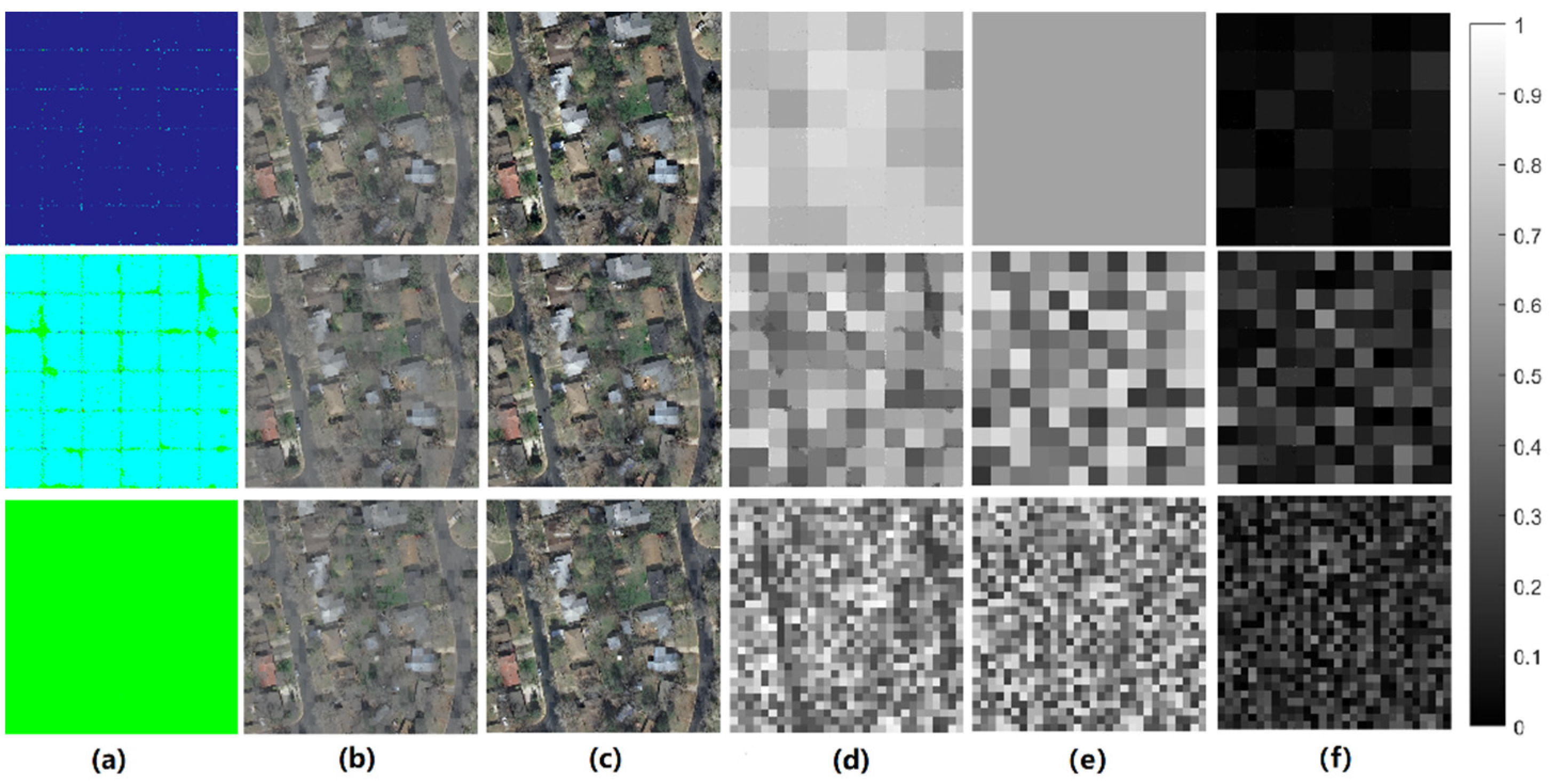
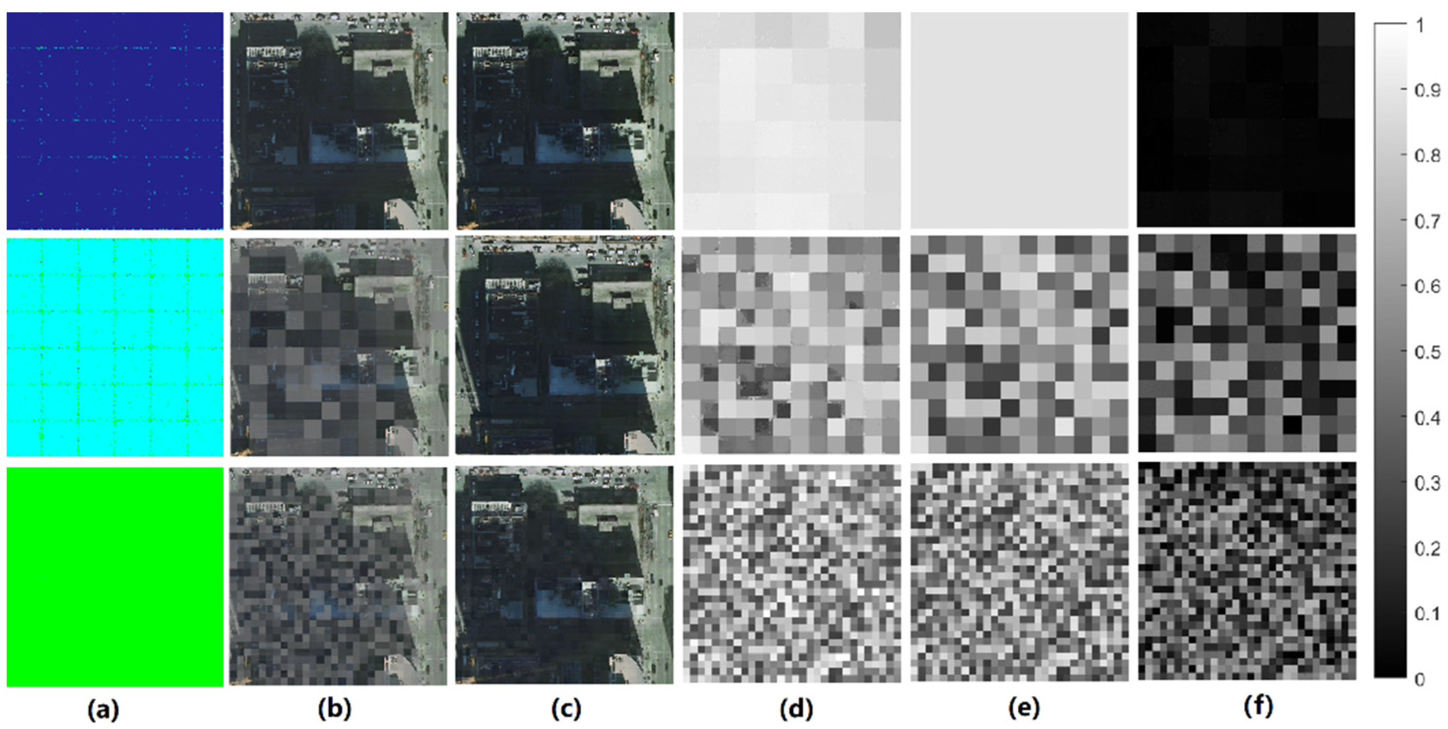
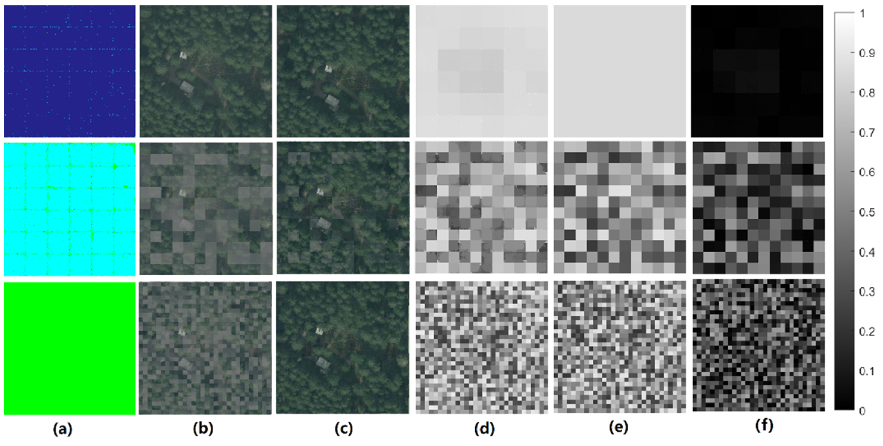
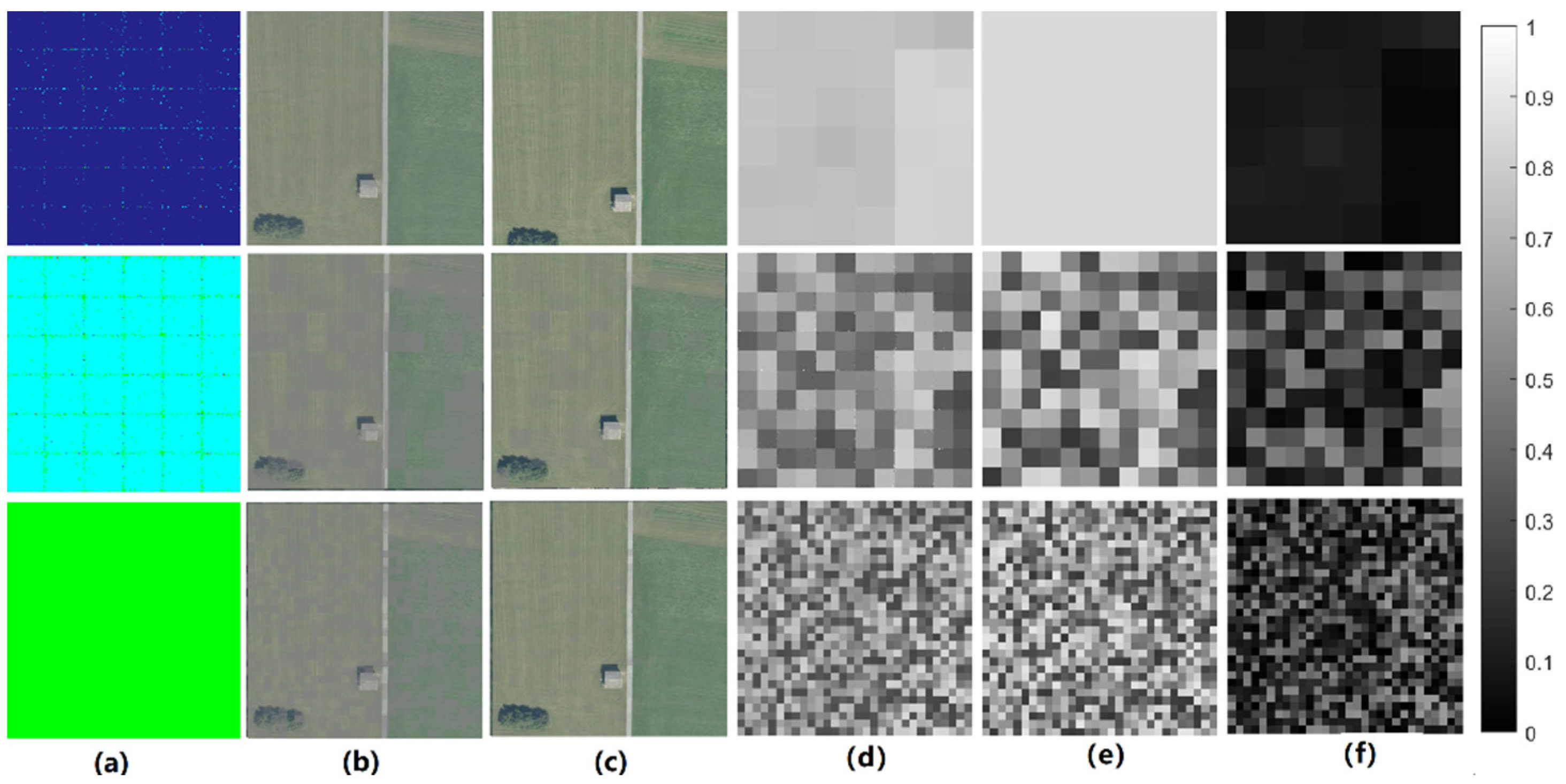
The one-step DRL_Dehaze results are presented in Figure 4, Figure 5, Figure 6 and Figure 7. The one-step action chosen by the DRL method was related to the scale of the haze in the aerial image. DehazeNet70 was selected in the uniform-haze situation, whereas DehazeNet35 was selected in the medium-scale haze situation, and DehazeNet14 was usually chosen in a small-scale haze situation.
The DRL_Dehaze method can choose the most suitable method for different scales of haze in images.
We calculated the PSNR and SSIM indicators of the one-step DRL_Dehaze method at different dehazing scales. We also calculated the MSEs of the estimated atmospheric transmissions with respect to the true values, as listed in Table 3.
The MSE of the atmospheric transmission was closely related to the estimated clear-image quality. The prediction results for the uniform-haze situations were better than those for the medium-scale haze situations, and the small-scale haze situations were the most difficult to predict.

5.2. Two-Step DRL_Dehaze Results

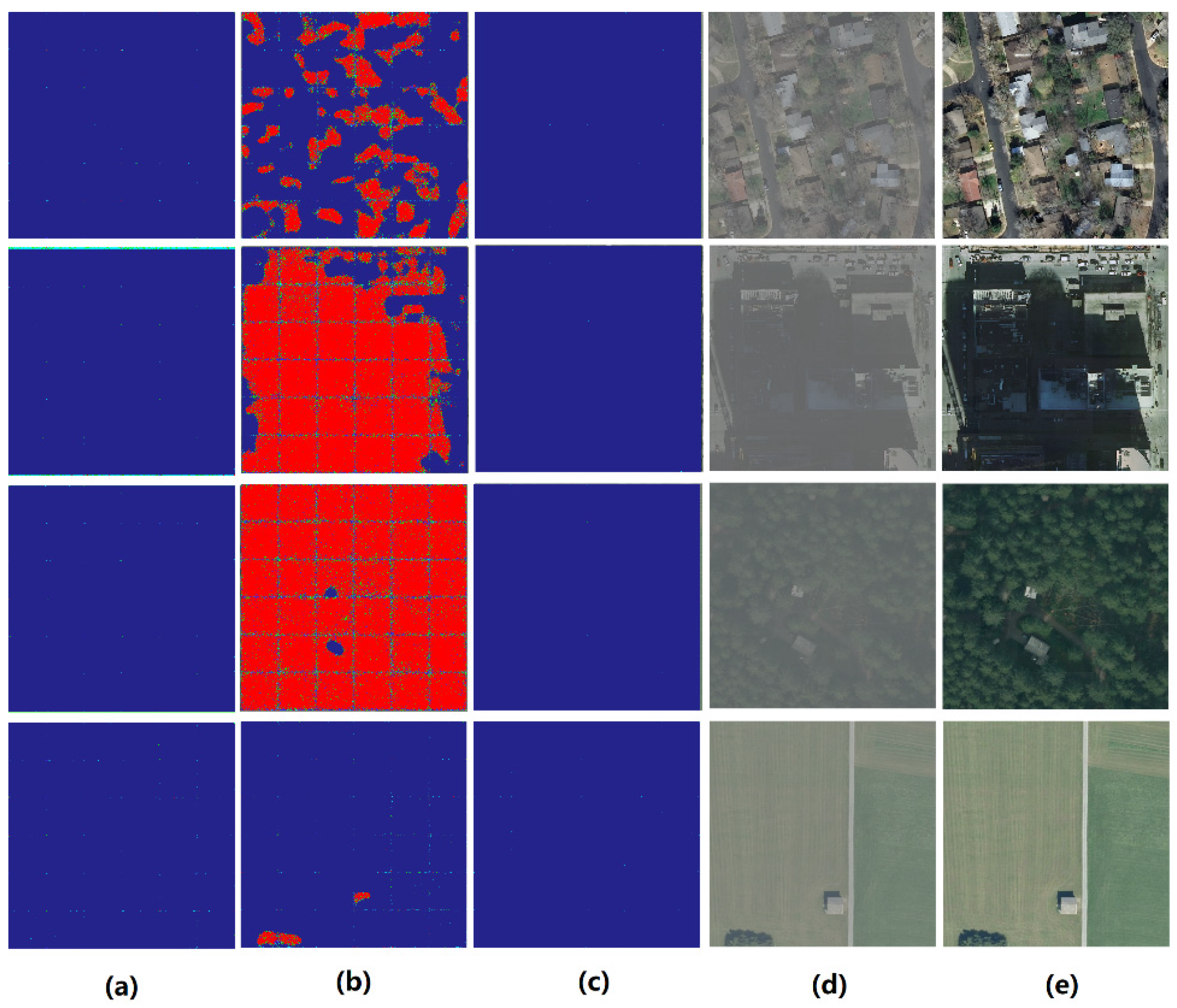
The two-step DRL_Dehaze results are shown in Figure 8. Only the uniform-haze situation was tested in this part. In the first step, the method selected the best dehazing method that matched the haze scale, which was the same choice selected in the one-step DRL_Dehaze method.
At the beginning of the DRL training process, in the second step, a repair was performed on some sections of the image. The repair step was mainly the pixel-value decrement action, but included a few other actions, as can be observed in Figure 8. The repaired sections of the image were mainly the areas that were relatively dark, such as the shaded, black soil, and canopy areas.
As the DRL training proceeded, the repair action disappeared; this is reasonable for aerial data, because the haze distribution is irrelevant for special types of ground and is only related to the atmosphere itself. That is, for a uniform-haze image, the action chosen should be the same one used for the whole image. The dehazed image result presented in Figure 8e used the actions of Figure 8a,c.

5.3. Three-Step DRL_Dehaze Results

The three-step DRL_Dehaze results are presented in Figure 9. The chosen action was similar to that selected in the two-step DRL_Dehaze situation. At the beginning of the DRL training process, the agents selected the repair operations in steps 2 and 3. As the training proceeded, a uniform DehazeNet action was performed in steps 2 and 3.

5.4. Quantitative Evaluations

Table 4 and Figure 10 present the quantitative evaluation results of the DehazeNet method and DRL_Dehaze methods proposed in this article.
The DRL_Dehaze method performed well on different ground types. On the residential area image, the one-step DRL_Dehaze performed the best. On the city area image, which had many shadows, the two-step DRL_Dehaze method provided a better result. This was due to the underestimation of the atmospheric influence due to the building’s shadows. Additionally, in some forest and farmland areas, the decreased brightness of the image may lead to a low estimate of atmospheric transmission parameters, and a better dehazing result can be obtained by the multi-step dehazing method.
We also provided the runtime of the methods in Table 3; the two- and three-step DRL_Dehaze methods were slower than the one-step method. However, the total runtimes were not excessive.

6. Conclusions

In this study, we developed a DRL_Dehaze method based on pixelRL. A clear–haze multi-scale aerial dataset was developed. One-, two-, and three-step DRL_Dehaze methods were tested on the dataset. Each pixel agent selected the most suitable method for dehazing after training. In traditional methods, only one method can be selected for the whole image in general. By contrast, DRL_Dehaze allows a different method to be chosen for each pixel, and multi-step processing to realize the comprehensive application of various dehazing algorithms.
The quantitative results show that the one-step DRL_Dehaze method performs the best in most cases, but in the city areas, where many shadows exist, the two- and three-step DRL_Dehaze methods are better. Furthermore, in the DRL_Dehaze model training process, the evolution of the chosen methods revealed an interesting disappearance of structural properties. This is reasonable given the hazy properties of the aerial data.
In future studies, multi-scale haze existing in the same image could be tested: this situation reflects real-life scenarios. Furthermore, sub-band dehazing of aerial data could be studied. In the actual aerial imaging process, the degree of transmission and scattering of the atmosphere varies according to the wavelength of light. The longer the wavelength, the greater its transmittance in the atmosphere. The achromatic aberration of aerial or remote-sensing images may be caused by the long-distance transmissions of light from the ground object to the aircraft.

Author Contributions

Methodology, J.Y. and D.L.; software, J.Y. and D.L.; writing—original draft preparation, J.Y.; writing—review and editing, D.L.; supervision, B.H.; project administration, H.G. All authors have read and agreed to the published version of the manuscript.

Funding

This research received no external funding.

Data Availability Statement

Not applicable.

Conflicts of Interest

The authors declare no conflict of interest.

References

  1. Guo, H.; Gu, X.F.; Xie, D.H.; Yu, T.; Meng, Q.Y. A review of atmospheric aerosol research by using polarization remote sensing. Spectrosc. Spectr. Anal. 2014, 34, 1873–1880. [Google Scholar]
  2. Li, Z.; Chen, X.; Ma, Y.; Qie, L.; Hou, W.; Qiao, Y. An overview of atmospheric correction for optical remote sensing satellites. J. Nanjing Univ. Inf. Sci. Technol. Nat. Sci. Ed. 2018, 10, 6–15. [Google Scholar]
  3. Griffin, M.K.; Burke, H.H. Compensation of hyperspectral data for atmospheric effects. Linc. Lab. J. 2003, 14, 29–54. [Google Scholar]
  4. Gao, B.C.; Montes, M.J.; Davis, C.O.; Goetz, A.F. Atmospheric correction algorithms for hyperspectral remote sensing data of land and ocean. Remote Sens. Environ. 2009, 113, S17–S24. [Google Scholar] [CrossRef]
  5. Minu, S.; Shetty, A. Atmospheric correction algorithms for hyperspectral imageries: A review. Int. Res. J. Earth Sci. 2015, 3, 14–18. [Google Scholar]
  6. He, K.; Sun, J.; Tang, X. Single image haze removal using dark channel prior. IEEE Trans. Pattern Anal. Mach. Intell. 2010, 33, 2341–2353. [Google Scholar] [PubMed]
  7. Zhu, Q.; Mai, J.; Shao, L. A fast single image haze removal algorithm using color attenuation prior. IEEE Trans. Image Process. 2015, 24, 3522–3533. [Google Scholar] [CrossRef] [PubMed] [Green Version]
  8. Berman, D.; Avidan, S. Non-local image dehazing. In Proceedings of the IEEE Conference on Computer Vision and Pattern Recognition, Las Vegas, NV, USA, 26 June–1 July 2016; pp. 1674–1682. [Google Scholar]
  9. Ren, W.; Liu, S.; Zhang, H.; Pan, J.; Cao, X.; Yang, M.H. Single image dehazing via multi-scale convolutional neural networks. In Proceedings of the 14th European Conference on Computer Vision, Amsterdam, The Netherlands, 11–14 October 2016; pp. 154–169. [Google Scholar]
  10. Cai, B.; Xu, X.; Jia, K.; Qing, C.; Tao, D. DehazeNet: An end-to-end system for single image haze removal. IEEE Trans. Image Process. 2016, 25, 5187–5198. [Google Scholar] [CrossRef] [PubMed] [Green Version]
  11. Li, B.; Peng, X.; Wang, Z.; Xu, J.; Feng, D. AOD-Net: All-in-one dehazing network. In Proceedings of the IEEE International Conference on Computer Vision, Venice, Italy, 26–29 October 2017; pp. 4770–4778. [Google Scholar]
  12. Narasimhan, S.G.; Nayar, S.K. Vision and the atmosphere. Int. J. Comput. Vis. 2002, 48, 233–254. [Google Scholar] [CrossRef]
  13. Tan, R.T. Visibility in bad weather from a single image. In Proceedings of the 2008 IEEE Conference on Computer Vision and Pattern Recognition, Anchorage, AK, USA, 23–28 June 2008; IEEE: Piscataway, NJ, USA, 2008; pp. 1–8. [Google Scholar]
  14. Fattal, R. Single image dehazing. ACM Trans. Graph. TOG 2008, 27, 1–9. [Google Scholar] [CrossRef]
  15. Kang, J.; Woo, S.S. DLPNet: Dynamic Loss Parameter Network using Reinforcement Learning for Aerial Imagery Detection. In Proceedings of the 2021 4th International Conference on Artificial Intelligence and Pattern Recognition, Xiamen, China, 24–26 September 2021; pp. 191–198. [Google Scholar]
  16. Liu, S.; Tang, J. Modified deep reinforcement learning with efficient convolution feature for small target detection in VHR remote sensing imagery. ISPRS Int. J. Geo-Inf. 2021, 10, 170. [Google Scholar] [CrossRef]
  17. Uzkent, B.; Yeh, C.; Ermon, S. Efficient object detection in large images using deep reinforcement learning. In Proceedings of the IEEE/CVF Winter Conference on Applications of Computer Vision, Snowmass Village, CO, USA, 2–5 March 2020; pp. 1824–1833. [Google Scholar]
  18. Fu, K.; Li, Y.; Sun, H.; Yang, X.; Xu, G.; Li, Y.; Sun, X. A ship rotation detection model in remote sensing images based on feature fusion pyramid network and deep reinforcement learning. Remote Sens. 2018, 10, 1922. [Google Scholar] [CrossRef] [Green Version]
  19. Casanova, A.; Pinheiro, P.O.; Rostamzadeh, N.; Pal, C.J. Reinforced active learning for image segmentation. arXiv 2020, arXiv:2002.06583. [Google Scholar]
  20. Li, X.; Zheng, H.; Han, C.; Wang, H.; Dong, K.; Jing, Y.; Zheng, W. Cloud detection of superview-1 remote sensing images based on genetic reinforcement learning. Remote Sens. 2020, 12, 3190. [Google Scholar] [CrossRef]
  21. Feng, J.; Li, D.; Gu, J.; Cao, X.; Shang, R.; Zhang, X.; Jiao, L. Deep reinforcement learning for semisupervised hyperspectral band selection. IEEE Trans. Geosci. Remote Sens. 2021, 60, 5501719. [Google Scholar] [CrossRef]
  22. Mou, L.; Saha, S.; Hua, Y.; Bovolo, F.; Bruzzone, L.; Zhu, X.X. Deep reinforcement learning for band selection in hyperspectral image classification. IEEE Trans. Geosci. Remote Sens. 2021, 60, 5504414. [Google Scholar] [CrossRef]
  23. Bhatt, J.S.; Joshi, M.V. Deep learning in hyperspectral unmixing: A review. In Proceedings of the IGARSS 2020—2020 IEEE International Geoscience and Remote Sensing Symposium, Waikoloa, HI, USA, 26 September–2 October 2020; IEEE: Piscataway, NJ, USA, 2020; pp. 2189–2192. [Google Scholar]
  24. Chu, X.; Zhang, B.; Ma, H.; Xu, R.; Li, Q. Fast, accurate and lightweight super-resolution with neural architecture search. In Proceedings of the 2020 25th International Conference on Pattern Recognition (ICPR), Milan, Italy, 10–15 January 2021; IEEE: Piscataway, NJ, USA, 2021; pp. 59–64. [Google Scholar]
  25. Rout, L.; Shah, S.; Moorthi, S.M.; Dhar, D. Monte-Carlo Siamese policy on actor for satellite image super resolution. In Proceedings of the IEEE/CVF Conference on Computer Vision and Pattern Recognition Workshops, Seattle, WA, USA, 14–19 June 2020; pp. 194–195. [Google Scholar]
  26. Vassilo, K.; Heatwole, C.; Taha, T.; Mehmood, A. Multi-step reinforcement learning for single image super-resolution. In Proceedings of the IEEE/CVF Conference on Computer Vision and Pattern Recognition Workshops, Seattle, WA, USA, 14–19 June 2020; pp. 512–513. [Google Scholar]
  27. Furuta, R.; Inoue, N.; Yamasaki, T. Fully convolutional network with multi-step reinforcement learning for image processing. Proc. AAAI Conf. Artif. Intell. 2019, 33, 3598–3605. [Google Scholar] [CrossRef] [Green Version]
  28. Furuta, R.; Inoue, N.; Yamasaki, T. Pixelrl: Fully convolutional network with reinforcement learning for image processing. IEEE Trans. Multimed. 2019, 22, 1704–1719. [Google Scholar] [CrossRef] [Green Version]
  29. Li, W.; Feng, X.; An, H.; Ng, X.Y.; Zhang, Y.-J. Mri reconstruction with interpretable pixel-wise operations using reinforcement learning. Proc. AAAI Conf. Artif. Intell. 2020, 34, 792–799. [Google Scholar] [CrossRef]
  30. Liao, X.; Li, W.; Xu, Q.; Wang, X.; Jin, B.; Zhang, X.; Wang, Y.; Zhang, Y. Iteratively-refined interactive 3D medical image segmentation with multi-agent reinforcement learning. In Proceedings of the IEEE/CVF Conference on Computer Vision and Pattern Recognition, Seattle, WA, USA, 13–19 June 2020; pp. 9394–9402. [Google Scholar]
  31. Anh, T.T.; Nguyen-Tuan, K.; Quan, T.M.; Jeong, W.K. Reinforced Coloring for End-to-End Instance Segmentation. arXiv 2020, arXiv:2005.07058. [Google Scholar]
  32. Mnih, V.; Badia, A.P.; Mirza, M.; Graves, A.; Lillicrap, T.; Harley, T.; Silver, D.; Kavukcuoglu, K. Asynchronous methods for deep reinforcement learning. In Proceedings of the International Conference on Machine Learning, PMLR, New York, NY, USA, 19–24 June 2016; pp. 1928–1937. [Google Scholar]
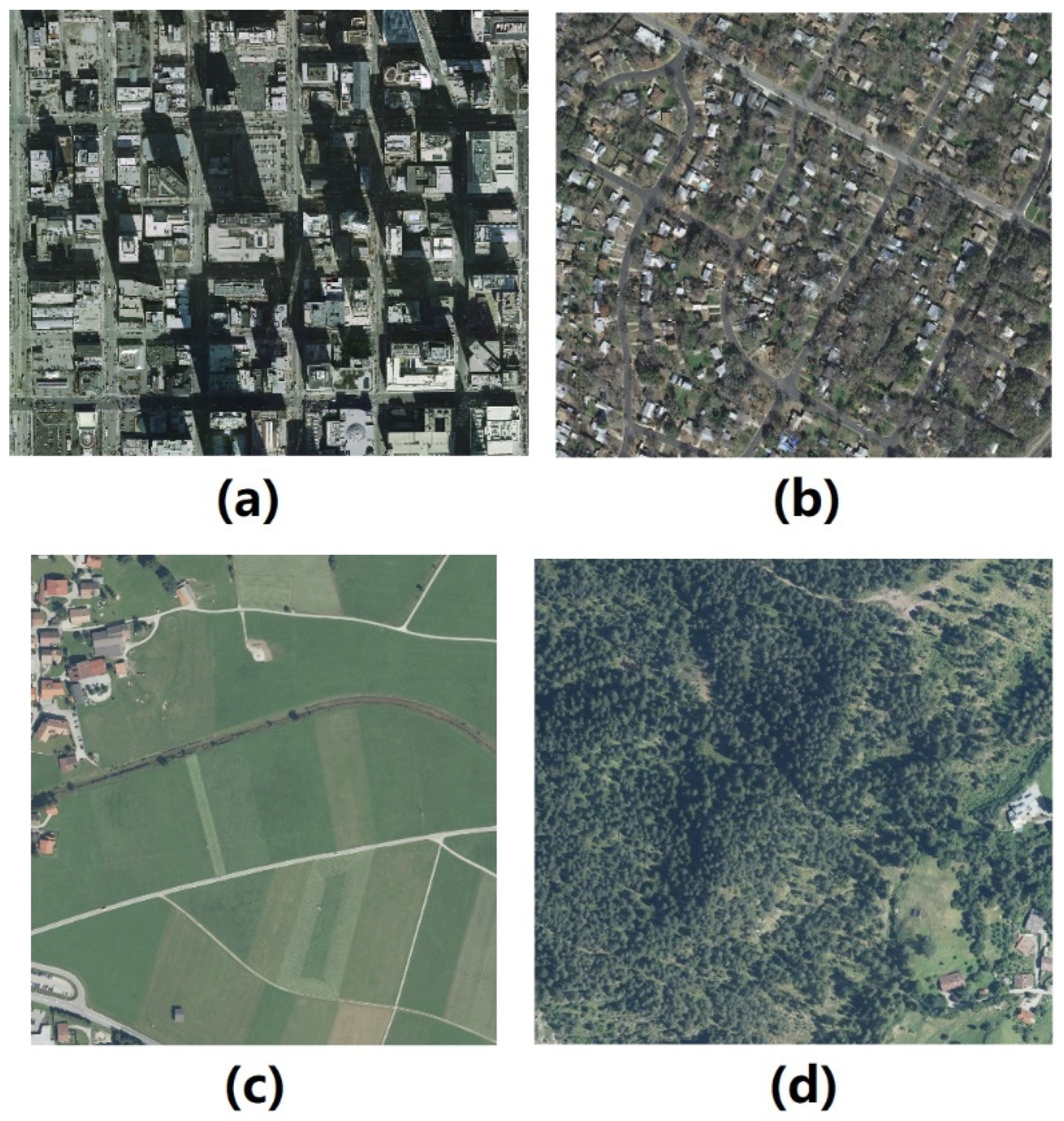
Figure 1. Typical images selected from the INRIA Aerial Image Labeling dataset to create the dehazing dataset: (a) city, (b) residential, (c) farmland, and (d) forest areas.
Remotesensing 14 05998 g001
Figure 2. Multi-scale haze-image training dataset. (a) Distribution of the transmission of the atmosphere and (b) hazy image caused by the atmosphere transmission of (a).
Remotesensing 14 05998 g002
Figure 3. PixelRL network architecture [28]. The numbers in the table indicate the filter size, dilation factor, and output channels, respectively.
Remotesensing 14 05998 g003
Figure 4. One-step DRL_Dehaze results for different haze scales in a residential area. The first row presents the uniform-haze situation, the second row presents the medium-scale haze situation, and the last row presents the small-scale haze situation. (a) Action maps of the hazy aerial images, (b) hazy aerial images, (c) dehazed clear image of (b,d) predicted atmosphere transmission map, (e) ground truth values of the atmosphere transmission maps, and (f) differences in the predicted and true atmosphere transmissions. The bar on the right provides reference values for (df).
Remotesensing 14 05998 g004
Figure 5. One-step DRL_Dehaze results for different haze scales in a city area. The first row presents the uniform-haze situation, the second row presents the medium-scale haze situation, and the last row presents the small-scale haze situation. (a) Action maps of the hazy aerial images, (b) hazy aerial images, (c) dehazed clear images of (b,d) predicted atmosphere transmission maps, (e) ground truth values of the atmosphere transmission maps, and (f) differences in the predicted and true atmosphere transmissions. The bar on the right provides reference values for (df).
Remotesensing 14 05998 g005
Figure 6. One-step DRL_Dehaze results of different haze scales in forest area. The first row presents the uniform-haze situation, the second row presents the medium-scale haze situation, and the last row presents the small-scale haze situation. (a) Action maps of the hazy aerial image, (b) hazy aerial image, (c) dehazed clear image of (b,d) predicted atmosphere transmission map, (e) ground truth values of the atmosphere transmission maps, and (f) differences in the predicted and true atmosphere transmissions. The bar on the right provides reference values for (df).
Remotesensing 14 05998 g006
Figure 7. One-step DRL_Dehaze results of different haze scales in farmland area. The first row presents the uniform-haze situation, the second row presents the medium-scale haze situation, and the last row presents the small-scale haze situation. (a) Action maps of the hazy aerial images, (b) hazy aerial images, (c) dehazed clear images of (b,d) predicted atmosphere transmission maps, (e) ground truth values of the atmosphere transmission maps, and (f) differences in the predicted and true atmosphere transmissions. The bar on the right provides reference values for (df).
Remotesensing 14 05998 g007
Figure 8. Two-step DRL_Dehaze results at a uniform-haze scale in various areas. (a) First action maps, (b) second action maps (at the beginning of the DRL training process), (c) second action maps (after the DRL training has advanced), (d) hazy aerial images, and (e) dehazed clear aerial images (action (a,c) maps are adopted).
Remotesensing 14 05998 g008
Figure 9. Three-step DRL_Dehaze result at a uniform-haze scale in various areas. (a) First action maps, (b) second action maps (at the beginning of the DRL training process), (c) second action maps (when the DRL training has advanced), (d) third action maps (at the beginning of the DRL training process), (e) third action maps (when the DRL training has advanced), and (f) hazy aerial images, (g) dehazed clear aerial images (action (a,c) maps are adopted).
Remotesensing 14 05998 g009
Figure 10. Comparation of DehazeNet and the DRL_Dehaze methods in various areas.
Remotesensing 14 05998 g010
Table 1. Quantitative evaluation results of different methods.
Ground FeatureEvaluation Indicators Atmosphere TransmissionHazy
Image
DCPCAPNLDDehazeNetAODNetMSCNN
Residential areaPSNRR1 *0.6423.4220.7324.7212.5927.3623.7730.75 **
R20.8727.8013.8418.2013.4927.9519.7725.00
SSIMR10.640.920.940.980.590.970.940.98
R20.870.960.840.900.660.970.900.95
CitiesPSNRC10.2514.2119.6419.6916.4327.2120.1023.43
C20.8928.5121.6223.2618.0428.6227.3224.50
SSIMC10.250.620.920.900.780.970.900.92
C20.890.970.860.920.740.970.960.87
ForestsPSNRFO10.8527.6723.3031.6519.8238.1225.4434.24
FO20.2913.3628.3220.5514.1927.1030.0126.29
SSIMFO10.850.980.890.980.710.990.890.99
FO20.290.670.940.890.640.960.970.96
FarmlandsPSNRFA10.7026.7911.6518.5716.0328.0119.3526.48
FA20.8540.9311.8923.7317.9341.0635.7133.17
SSIMFA10.700.970.770.870.810.980.860.96
FA20.851.000.700.980.881.000.990.99
* R1, R2: residential area image groups; C1, C2: city area image groups; FO1, FO2: forest area image groups; FA1, FA2: farmland area groups. ** Bold font represents the best method.
Table 2. Action set used in DRL_Dehaze.
Serial NumberActionColor
0Pixel value − = 1Remotesensing 14 05998 i001
1do nothingRemotesensing 14 05998 i002
2Pixel value + = 1Remotesensing 14 05998 i003
3DehazeNet14Remotesensing 14 05998 i004
4DehazeNet35Remotesensing 14 05998 i005
5DehazeNet70Remotesensing 14 05998 i006
6DCPRemotesensing 14 05998 i007
Table 3. Quantitative evaluation results of one-step DRL_Dehaze methods for different dehazing scales in the images.
Image
Group Name
Uniform-Haze
Situation
Medium-Haze
Situation
Small-Scale Haze
Situation
PSNRSSIMMSE **PSNRSSIMMSE **PSNRSSIMMSE **
R1 *34.540.991.0227.390.9612.6227.260.9613.26
R227.300.977.4327.160.9519.5126.510.9621.65
C126.570.952.3123.770.9522.7225.430.9422.82
C238.421.000.4127.890.9637.0425.230.9241.40
FO142.091.000.1533.090.9831.5326.470.9432.54
FO226.190.951.1724.800.9519.1222.710.9021.16
FA138.831.001.2631.210.9823.1629.280.9726.50
FA242.531.002.0542.241.0022.7240.151.0024.24
* R1, R2: residential area image groups; C1, C2: city area image groups; FO1, FO2: forest area image groups; FA1, FA2: farmland area groups. ** MSE: here the MSE is of the estimated atmospheric transmissions with respect to the true values.
Table 4. Quantitative evaluation results of DehazeNet methods and the DRL_Dehaze methods.
Ground FeatureEvaluation Indicators Hazy
Image
Dehaze
Net
One-Step DRL_DehazeTwo-Step DRL_DehazeThree-Step DRL_Dehaze
Residential areaPSNRR1 **23.4227.3634.54 *25.8823.42
R227.8027.3027.9525.5822.09
SSIMR10.920.970.990.960.93
R20.960.970.970.960.92
CitiesPSNRC114.2127.2123.7730.2826.62
C228.5128.6238.4236.8733.88
SSIMC10.620.970.950.990.97
C20.970.971.000.990.99
ForestsPSNRFO127.6738.1242.0934.7231.84
FO213.3627.1024.8032.9037.19
SSIMFO10.980.991.000.990.99
FO20.670.960.950.991.00
FarmlandsPSNRFA126.7928.0138.8339.6236.34
FA240.9341.0642.5335.8532.15
SSIMFA10.970.981.001.001.00
FA21.001.001.000.990.99
Time consumption (second)-1.816.3020.121.4
* Bold font represents the best method.** R1, R2: residential area image groups; C1, C2: city area image groups; FO1, FO2: forest area image groups; FA1, FA2: farmland area groups.
Publisher’s Note: MDPI stays neutral with regard to jurisdictional claims in published maps and institutional affiliations.