

A Separate Calibration Method of Laser Pointing and Ranging for the GF-7 Satellite Laser That Does Not Require Field Detectors


Abstract
1. Introduction
2. Materials and Methods
2.1. Study Area
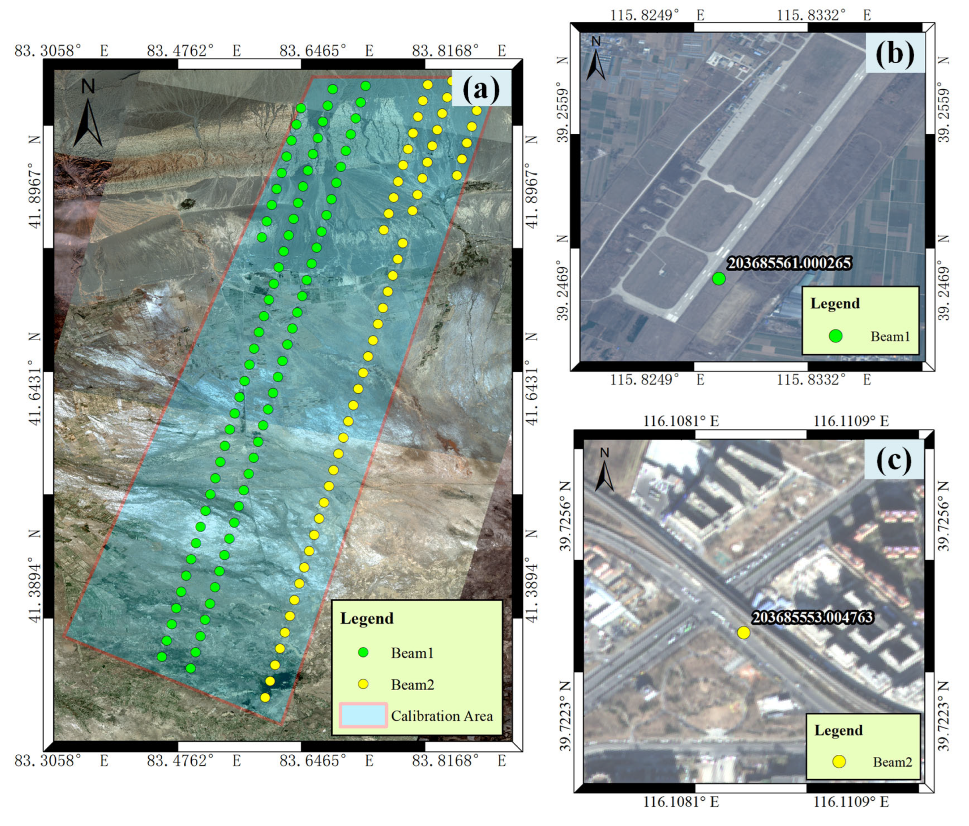
2.1.1. Calibration Area
- (1)
- Point Calibration Area
- (2)
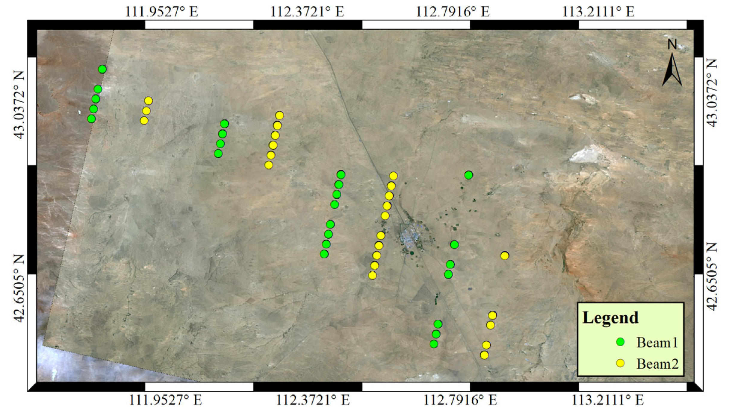
- Ranging Calibration Area
2.1.2. Elevation Accuracy Validation Area
2.2. Data
2.2.1. GF-7 Satellite Laser Data
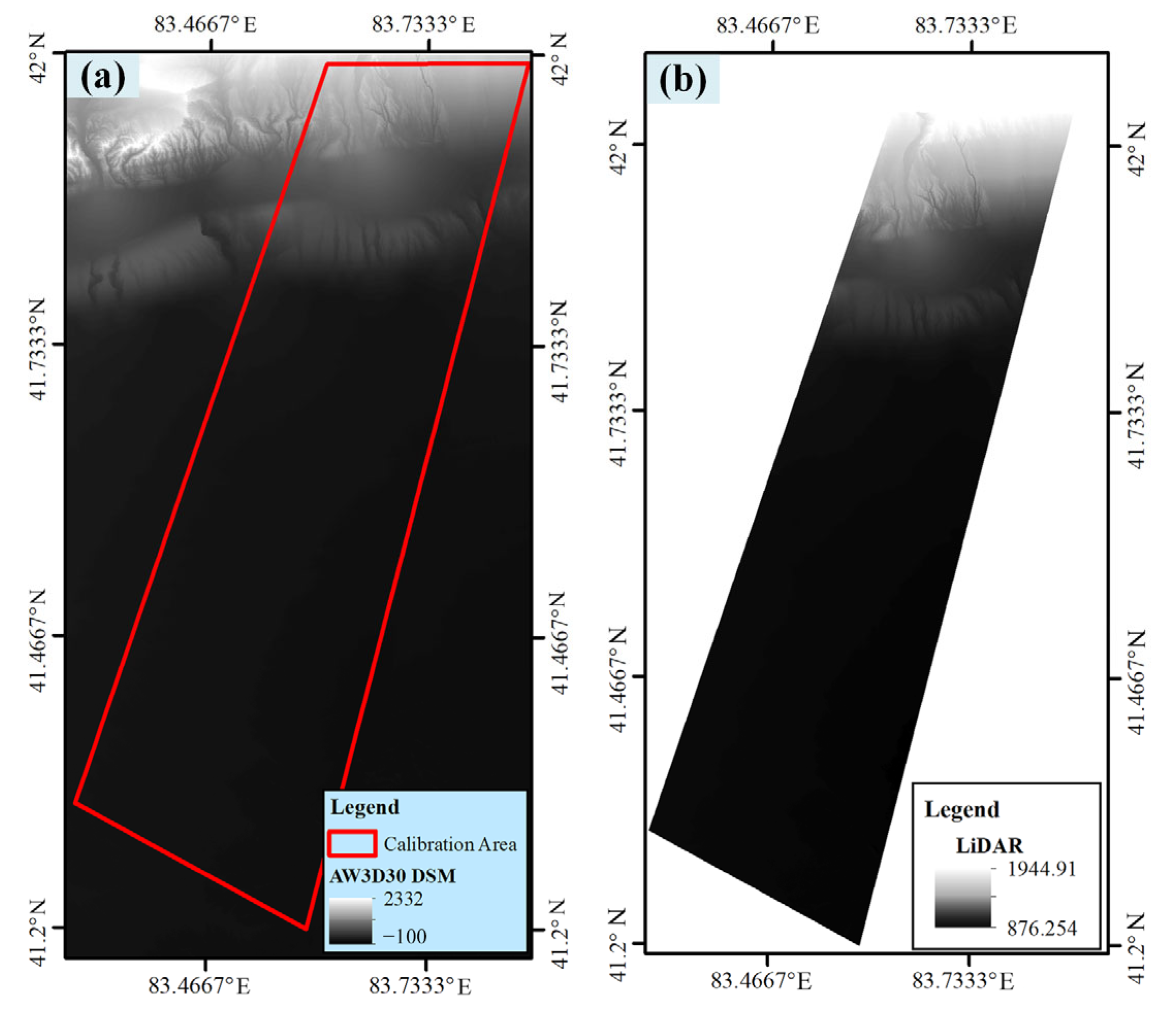
2.2.2. Reference Terrain Data
- (1)
- AW3D30 DSM
- (2)
- LiDAR Data
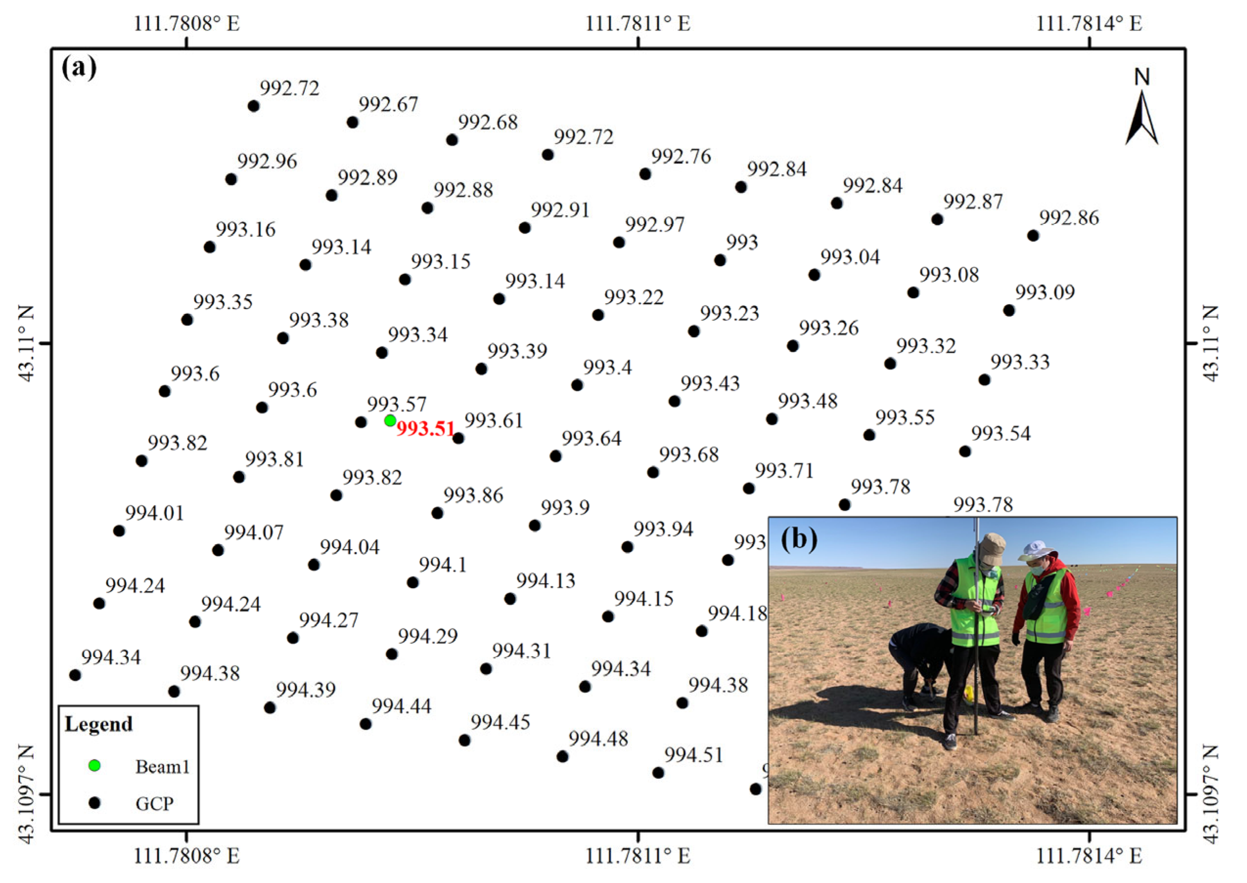
2.2.3. GCPs Dataset
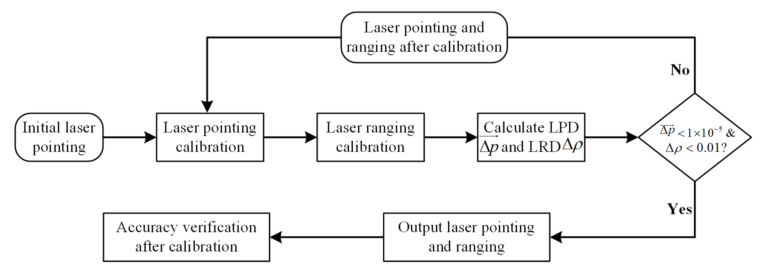
2.3. Methodology
- Step 1:
- Experimental data preparation: initial pointing parameters, initial ranging error (0 by default), GF-7 laser data, reference DSM data, and the GCPs around the laser footprint.
- Step 2:
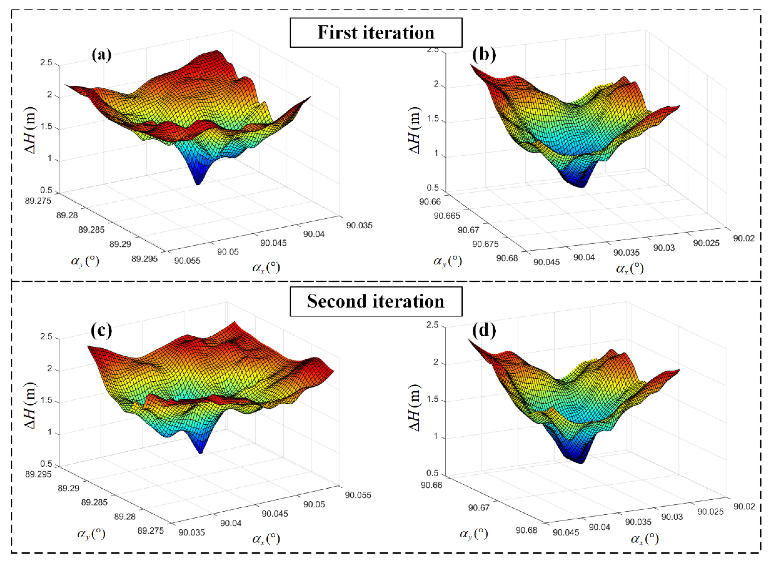
- Laser pointing calibration: First, a pointing angle grid is established with the initial laser pointing angle as the center. Then, the residual sum of the laser and the reference DSM elevation for each grid is calculated. The laser pointing angle with the smallest elevation residual sum between the laser and the DSM is used as the laser pointing angle after calibration.
- Step 3:
- Laser ranging calibration: taking the laser pointing angle after calibration as the input parameter, the coordinates of the laser footprint on the flat hard surface are calculated, and the elevation difference between the laser and the surface is used as the ranging error after calibration.
- Step 4:
- Iterative of laser pointing and ranging calibration: It must be assessed whether the laser point difference (LPD) between the calibrated pointing and the input pointing in step 2 is less than 1 × 10⁻⁵ degrees and whether the laser ranging difference (LRD) between the calibrated ranging error and the input ranging error in step 3 is less than 0.01 m. This is called the iterative convergence condition. When the convergence condition is satisfied, the output pointing and ranging error are the final iterative calibration results. Otherwise, redo steps 2–4 with the calibration result of this iteration as an input parameter. Typically, it takes 2–3 iterations to converge.
- Step 5:
- Accuracy verification after calibration: the laser pointing and ranging error value after calibration by LGDs is first used as the true value to verify the laser pointing and ranging accuracy following the calibration method outlined in this paper. Then, the GCPs are used to verify the elevation accuracy of GF-7 satellite laser after calibration.
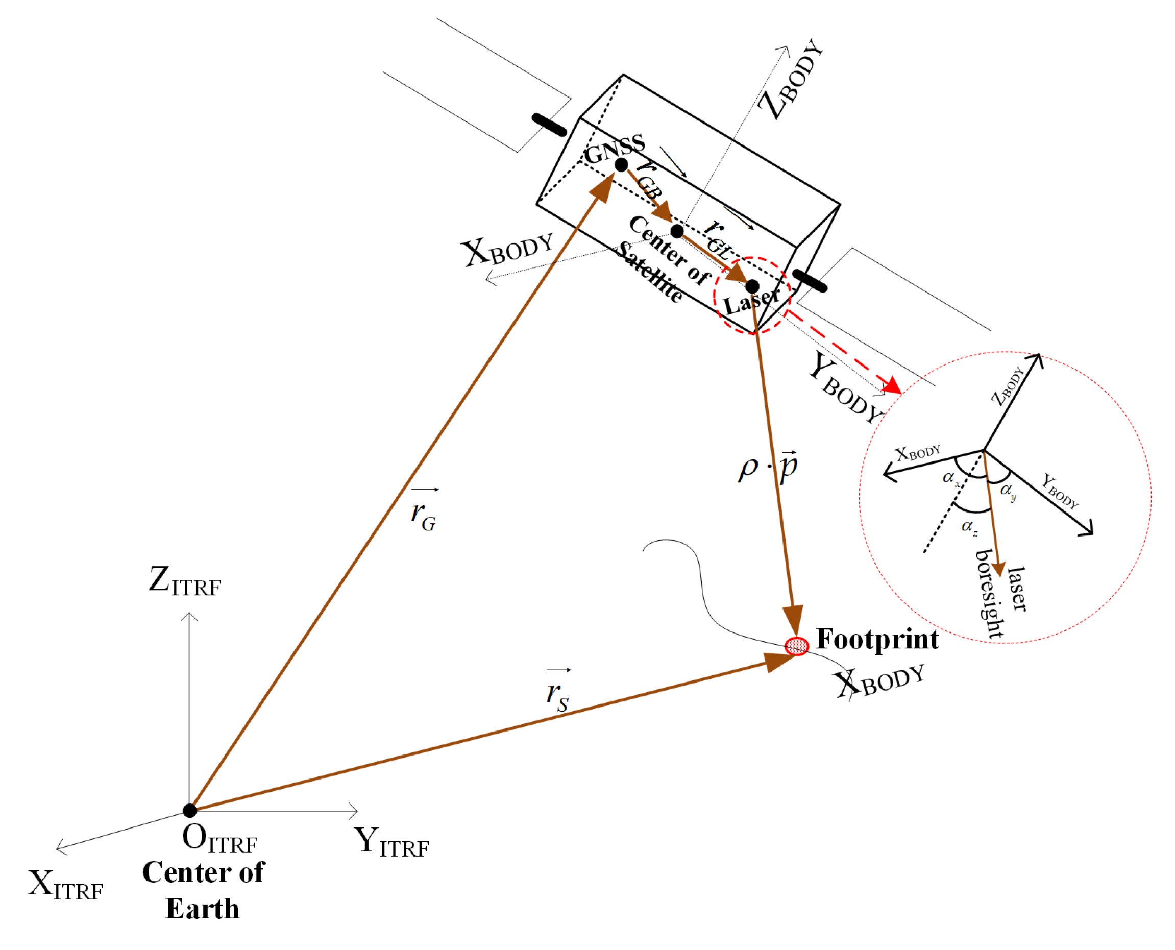
2.3.1. Satellite Pointing Error Calibration
| Algorithm 1: Satellite Laser Pointing Calibration |
| 1: Input: The Initial laser pointing . The pointing grid range . The pointing grid interval . The original laser data set . 2: Output: The pointing after calibration . 3: Generate a laser pointing grid with a length of and a width of . So, the laser pointing set is . There is total laser pointing 4: For = 1 to do 5: For = 1 to do 6: Compute the surface coordinates of the laser footprint using laser pointing . 7: Interpolate the elevation of the reference DSM using . 8: Calculate the elevation difference between and , . 9: end for 10: Count the mean of all laser elevation differences . 11: end for 12: Find the smallest in the elevation difference from dataset , and assume that its corresponding laser pointing is . Thus, . |
2.3.2. Satellite Ranging Error Calibration
2.3.3. Elevation Accuracy Verification of Satellite Laser
3. Results
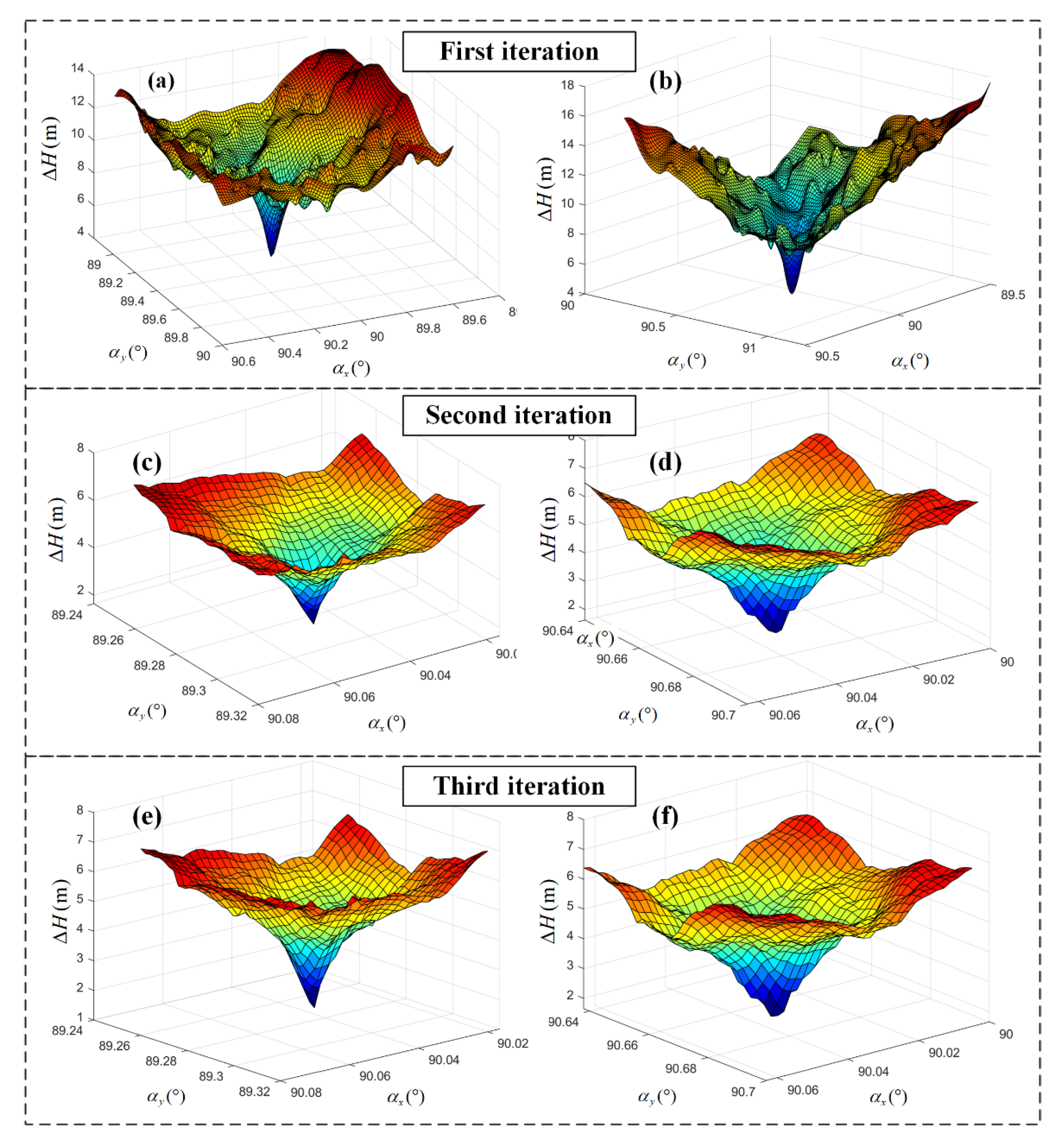
3.1. Calibration of Laser Pointing and Ranging
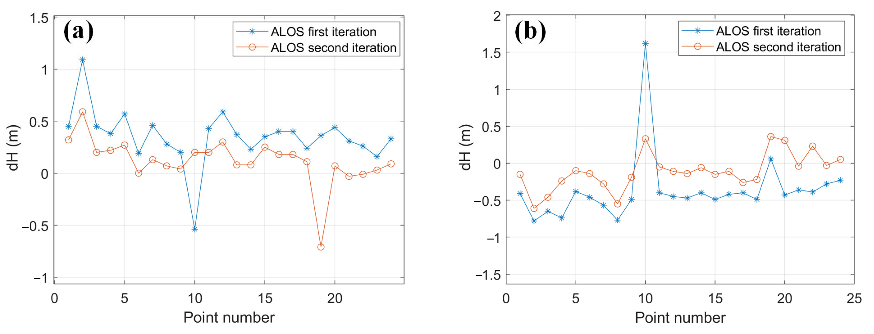
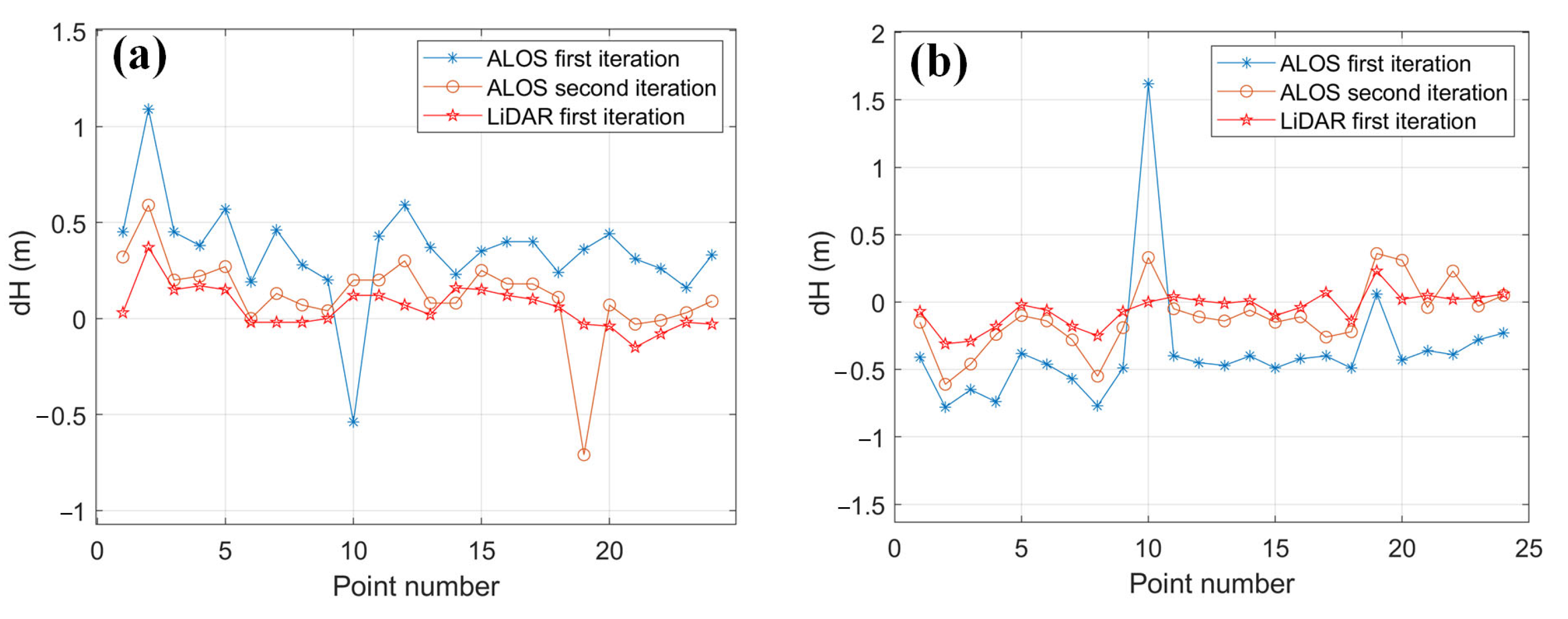
3.2. Elevation Accuracy Validation after Calibration
4. Discussion
5. Conclusions
- (1)
- The iterative calibration method for the separation of laser pointing and ranging proposed in this paper solves the ranging calibration problem that cannot be solved using traditional terrain matching laser calibration methods. The method proposed here can further improve the calibration accuracy of satellite lasers.
- (2)
- The convergence speed of this calibration method is fast. Typically, the satellite laser pointing angle converges after 2–3 iterations. Taking the AW3D30 DSM as the reference terrain data, the pointing angle accuracy of GF-7 beam 1 was 4.2 arcsec, and the ranging accuracy was 3 cm after the calibration. The pointing accuracy of the beam 2 was 4.7 arcsec, and the ranging accuracy was 6 cm.
- (3)
- High-precision DSM data can improve the accuracy of the calibration method. Based on the calibration results from the AW3D30 DSM as the reference terrain, when LiDAR data was used as the reference terrain data, the laser pointing and ranging accuracy of the GF-7 satellite was improved. The improved laser pointing accuracy of GF-7 satellite beam 1 was 2 arcsec, and the ranging accuracy was 2 cm. The GF-7 laser beam 2 pointing accuracy was 2.2 arcsec, and the ranging accuracy was 1 cm.
- (4)
- Using high-precision LiDAR data as the reference terrain data, the elevation accuracy of the GF-7 satellite laser was 0.18 m in flat terrain after the calibration, which was slightly lower than that of the calibration method based on the ground detector. However, it was still slightly lower than that of the calibration method based on LGDs.
Author Contributions
Funding
Data Availability Statement
Conflicts of Interest
Appendix A
- (1)
- GF-7 Satellite Laser Data Query

- (2)
- GF-7 satellite laser data request
References
- Tang, X.; Xie, J.; Liu, R.; Huang, G.; Zhao, C.; Zhen, Y.; Tang, H.; Dou, X. Overview of the GF-7 Laser Altimeter System Mission. Earth Space Sci. 2019, 6, e2019EA000777. [Google Scholar] [CrossRef]
- Xie, J.; Huang, G.; Liu, R.; Zhao, C.; Dai, J.; Jin, T.; Mo, F.; Zhen, Y.; Xi, S.; Tang, H.; et al. Design and Data Processing of China’s First Spaceborne Laser Altimeter System for Earth Observation: GaoFen-7. IEEE J. Sel. Top. Appl. Earth Obs. Remote Sens. 2020, 13, 1034–1044. [Google Scholar] [CrossRef]
- Luthcke, S.B.; Rowlands, D.D.; Williams, T.A.; Sirota, M. Reduction of ICESat systematic geolocation errors and the impact on ice sheet elevation change detection. Geophys. Res. Lett. 2005, 32, 312–321. [Google Scholar] [CrossRef]
- Luthcke, S.B.; Carabajal, C.C.; Rowlands, D.D. Enhanced geolocation of spaceborne laser altimeter surface returns: Parameter calibration from the simultaneous reduction of altimeter range and navigation tracking data. J. Geodyn. 2002, 34, 447–475. [Google Scholar] [CrossRef]
- Luthcke, S.B.; Rowlands, D.D.; Mccarthy, J.J.; Pavlis, D.E.; Stoneking, E. Spaceborne Laser-Altimeter-Pointing Bias Calibration from Range Residual Analysis. J. Spacecr. Rocket. 2000, 37, 374–384. [Google Scholar] [CrossRef]
- Rowlands, D.D.; Pavlis, D.E.; Lemoine, F.G.; Neumann, G.A.; Luthcke, S.B. The use of laser altimetry in the orbit and attitude determination of Mars Global Surveyor. Geophys. Res. Lett. 1999, 26, 1191–1194. [Google Scholar] [CrossRef]
- Magruder, L.A.; Webb, C.E.; Urban, T.J.; Silverberg, E.C.; Schutz, B.E. ICESat Altimetry Data Product Verification at White Sands Space Harbor. IEEE Trans. Geosci. Remote Sens. 2006, 45, 147–155. [Google Scholar] [CrossRef]
- Magruder, L.A.; Schutz, B.E.; Silverberg, E.C. Laser pointing angle and time of measurement verification of the ICESat laser altimeter using a ground-based electro-optical detection system. J. Geod. 2003, 77, 148–154. [Google Scholar] [CrossRef]
- Xie, J.; Tang, X.; Mo, F.; Tang, H.; Wang, Z.; Wang, X.; Liu, Y.; Tian, S.; Liu, R.; Xia, X. In-orbit geometric calibration and experimental verification of the ZY3-02 laser altimeter. Photogramm. Rec. 2018, 33, 341–362. [Google Scholar] [CrossRef]
- Tang, X.; Xie, J.; Mo, F.; Dou, X.; Li, X.; Li, S.; Li, S.; Huang, G.; Fu, X.; Liu, R.; et al. GF-7 dual-beam laser altimeter on-orbit geometric calibration and test verification. Acta Geod. Cartogr. Sin. 2021, 50, 384–395. [Google Scholar]
- Magruder, L.A.; Ricklefs, R.L.; Silverberg, E.C.; Horstman, M.F.; Suleman, M.A.; Schutz, B.E. ICESat Geolocation Validation Using Airborne Photography. IEEE Trans. Geosci. Remote Sens. 2010, 48, 2758–2766. [Google Scholar] [CrossRef]
- Liu, R.; Xie, J. Calibration of the laser pointing bias of the GaoFen-7 satellite based on simulation waveform matching. Opt. Express 2021, 29, 21844–21858. [Google Scholar] [CrossRef] [PubMed]
- Tang, X.; Xie, J.; Gao, X.; Mo, F.; Feng, W.; Liu, R. The In-Orbit Calibration Method Based on Terrain Matching with Pyramid-Search for the Spaceborne Laser Altimeter. IEEE J. Sel. Top. Appl. Earth Obs. Remote Sens. 2019, 12, 1053–1062. [Google Scholar] [CrossRef]
- Nan, Y.; Feng, Z.; Liu, E.; Li, B. Iterative Pointing Angle Calibration Method for the Spaceborne Photon-Counting Laser Altimeter Based on Small-Range Terrain Matching. Remote Sens. 2019, 11, 2158. [Google Scholar] [CrossRef]
- Takaku, J.; Tadono, T.; Tsutsui, K.; Ichikawa, M. Validation of “Aw3D” Global DSM Generated from Alos Prism. ISPRS Ann. Photogramm. Remote Sens. Spat. Inf. Sci. 2016, 3, 25–31. [Google Scholar]
- Takaku, J.; Tadono, T.; Tsutsui, K. Generation of high resolution global DSM from ALOS PRISM. Int. Arch. Photogramm. Remote Sens. Spat. Inf. Sci. ISPRS Arch. 2014, 40, 243–248. [Google Scholar]
- Mo, F.; Xie, J.; Liu, Y. In Evaluation of AW3D30 Elevation Accuracy in China. In Proceedings of the 4th International Conference on Geographical Information Systems Theory, Applications and Management, Madeira, Portugal, 17–19 March 2018. [Google Scholar]
- Schutz, B.E. Laser footprint location (geolocation) and surface profiles. In Geoscience Laser Altimeter System (GLAS): Algorithm Theoretical Basis Document Version 3; Center for Space Research of the University of Texas at Austin: Austin, TX, USA, 2002; pp. 1–24. [Google Scholar]
- Abshire, J.B.; Sun, X.; Riris, H.; Sirota, M.; Palm, S.; Ketchum, E.A. Geoscience laser altimeter system (GLAS) for the ICESat mission-pre-launch performance. In Proceedings of the Conference on Lasers and Electro-Optics (CLEO ‘03), Baltimore, MD, USA, 6 June 2003. [Google Scholar]
- Abdalati, W.; Zwally, H.J.; Bindschadler, R.; Csatho, B.; Farrell, S.L.; Fricker, H.A.; Harding, D.; Kwok, R.; Lefsky, M.; Markus, T.; et al. The ICESat-2 Laser Altimetry Mission. Proc. IEEE 2010, 98, 735–751. [Google Scholar] [CrossRef]
- Ma, Y.; Li, S.; Weng, Y.; Zhou, H. Hydrostatic delay correction for satellite laser altimeter. Infrared Laser Eng. 2013, 42, 909–914. [Google Scholar]
- The Algorithm Theoretical Basis Document for the Atmospheric Delay Correction to GLAS Laser Altimeter Ranges. Available online: https://ntrs.nasa.gov/search.jsp?R=20130001652 (accessed on 2 June 2012).
- Jentzsch, G. Earth tides and ocean tidal loading. Lect. Notes Earth Sci. 2005, 66, 145–171. [Google Scholar]
- Zhao, P.; Li, S.; Ma, Y.; Liu, X.; Yang, J.; Yu, D. A new terrain matching method for estimating laser pointing and ranging systematic biases for spaceborne photon-counting laser altimeters. ISPRS J. Photogramm. 2022, 188, 220–236. [Google Scholar] [CrossRef]


| Type | File Name | Number of Laser Points | |
|---|---|---|---|
| Beam 1 | Beam 2 | ||
| Pointing calibration | KRN-GF7-20201014-005278-0000005703 | 37 | 39 |
| KRN-GF7-20201212-006160-0000006634 | 9 | 10 | |
| KSC-GF7-20210607-008851-0000010008 | 37 | 19 | |
| Ranging calibration | KSC-GF7-20200615-003419-0000003495 | 1 | 1 |
| Elevation accuracy verification | SYC-GF7-20200609-003326-0000003289 | 7 | 5 |
| SYC-GF7-20200614-003402-0000003397 | 5 | 3 | |
| SYC-GF7-20200619-003478-0000003529 | 4 | 6 | |
| KSC-GF7-20200624-003555-0000003615 | 8 | 10 | |
| Experiment | Beam Type | Surface Coordinates of Laser FOOTPRINTS | Surface Actual Elevation (m) | Ranging Error (m) | ||
|---|---|---|---|---|---|---|
| Latitude (°) | Longitude (°) | Elevation (m) | ||||
| First iteration | Beam 1 | 39.24695 | 115.82774 | 12.19 | 12.95 | −0.76 |
| Beam 2 | 39.72343 | 116.10928 | 35.78 | 36.14 | −0.36 | |
| Second iteration | Beam 1 | 39.24692 | 115.82793 | 12.30 | 12.95 | −0.65 |
| Beam 2 | 39.72347 | 116.10908 | 35.86 | 36.14 | −0.28 | |
| Third iteration | Beam 1 | 39.24692 | 115.82793 | 12.30 | 12.95 | −0.65 |
| Beam 2 | 39.72347 | 116.10908 | 35.86 | 36.14 | −0.28 | |
| GF-7 Laser Pointing Type | Beam 1 | Beam 2 | ||||
|---|---|---|---|---|---|---|
| Initial pointing | 0.031 | −0.038 | −1.01 | 0.107 | −0.044 | −1.26 |
| Pointing after first calibration | −0.00043 | 0.00316 | −0.08 | 0.00056 | 0.0033 | 0.14 |
| Pointing after second calibration | −0.00043 | 0.00116 | 0.03 | 0.00056 | 0.0013 | −0.06 |
| Pointing after third calibration | −0.00043 | 0.00116 | 0.03 | 0.00056 | 0.0013 | −0.06 |
| Point Number | First Iteration | Second Iteration | ||||||
|---|---|---|---|---|---|---|---|---|
| Latitude (°) | Longitude (°) | Laser Elevation | Latitude (°) | Longitude (°) | Laser Elevation | Latitude (°) | Longitude (°) | |
| 1 | 43.11004 | 111.78070 | 993.81 | 993.35 | 0.46 | 993.51 | 993.18 | 0.33 |
| 2 | 43.06836 | 111.76772 | 999.31 | 998.22 | 1.09 | 999.01 | 998.42 | 0.59 |
| 3 | 43.04752 | 111.76124 | 1046.36 | 1045.91 | 0.45 | 1046.06 | 1045.87 | 0.19 |
| 4 | 43.02668 | 111.75476 | 1043.75 | 1043.37 | 0.38 | 1043.45 | 1043.23 | 0.22 |
| 5 | 43.00584 | 111.74828 | 1029.45 | 1028.87 | 0.58 | 1029.15 | 1028.88 | 0.27 |
| 6 | 42.99202 | 112.13091 | 1074.51 | 1074.32 | 0.19 | 1074.21 | 1074.21 | 0 |
| 7 | 42.97117 | 112.12443 | 1084.89 | 1084.43 | 0.46 | 1084.59 | 1084.45 | 0.14 |
| 8 | 42.95032 | 112.11797 | 1092.55 | 1092.27 | 0.28 | 1092.25 | 1092.17 | 0.08 |
| 9 | 42.92947 | 112.11149 | 1092.13 | 1091.92 | 0.21 | 1091.83 | 1091.79 | 0.04 |
| 10 | 42.88124 | 112.46241 | 1039.26 | 1039.81 | −0.55 | 1038.96 | 1038.76 | 0.2 |
| 11 | 42.86038 | 112.45595 | 1041.01 | 1040.58 | 0.43 | 1040.71 | 1040.51 | 0.2 |
| 12 | 42.83952 | 112.44949 | 1041.04 | 1040.45 | 0.59 | 1040.74 | 1040.45 | 0.29 |
| 13 | 42.81866 | 112.44304 | 1051.06 | 1050.69 | 0.37 | 1050.76 | 1050.68 | 0.08 |
| 14 | 42.77694 | 112.43014 | 1050.33 | 1050.10 | 0.23 | 1050.03 | 1049.95 | 0.08 |
| 15 | 42.75607 | 112.42369 | 1051.81 | 1051.45 | 0.36 | 1051.51 | 1051.26 | 0.25 |
| 16 | 42.73521 | 112.41726 | 1067.35 | 1066.96 | 0.39 | 1067.05 | 1066.87 | 0.18 |
| 17 | 42.71435 | 112.41082 | 1075.33 | 1074.93 | 0.4 | 1075.03 | 1074.85 | 0.18 |
| 18 | 42.87520 | 112.82920 | 1076.66 | 1076.42 | 0.24 | 1076.36 | 1076.25 | 0.11 |
| 19 | 42.72912 | 112.78404 | 1086.30 | 1085.93 | 0.37 | 1086.00 | 1086.71 | −0.71 |
| 20 | 42.68738 | 112.77117 | 1090.22 | 1089.78 | 0.44 | 1089.92 | 1089.85 | 0.07 |
| 21 | 42.66651 | 112.76474 | 1089.20 | 1088.89 | 0.31 | 1088.91 | 1088.94 | −0.03 |
| 22 | 42.56215 | 112.73264 | 1119.02 | 1118.76 | 0.26 | 1118.72 | 1118.74 | −0.02 |
| 23 | 42.54128 | 112.72623 | 1133.86 | 1133.69 | 0.17 | 1133.56 | 1133.53 | 0.03 |
| 24 | 42.52040 | 112.71982 | 1136.73 | 1136.40 | 0.33 | 1136.43 | 1136.34 | 0.09 |
| Mean value (m) | 0.35 | - | - | 0.12 | ||||
| RMSE (m) | 0.27 | - | - | 0.22 | ||||
| Point Number | First Iteration | Second Iteration | ||||||
|---|---|---|---|---|---|---|---|---|
| Latitude (°) | Longitude (°) | Laser Elevation(m) | GCP Elevation(m) | Elevation Difference(m) | Laser Elevation(m) | GCP Elevation(m) | Elevation Difference(m) | |
| 1 | 43.04254 | 111.91306 | 1053.10 | 1053.50 | −0.41 | 1053.50 | 1053.65 | −0.15 |
| 2 | 43.02171 | 111.90653 | 1056.06 | 1056.84 | −0.78 | 1056.47 | 1057.08 | −0.61 |
| 3 | 43.00087 | 111.89999 | 1065.71 | 1066.36 | −0.65 | 1066.12 | 1066.58 | −0.46 |
| 4 | 43.00798 | 112.28877 | 1044.74 | 1045.48 | −0.74 | 1045.15 | 1045.39 | −0.24 |
| 5 | 42.98714 | 112.28224 | 1071.27 | 1071.65 | −0.38 | 1071.68 | 1071.77 | −0.10 |
| 6 | 42.96629 | 112.27571 | 1078.84 | 1079.30 | −0.46 | 1079.24 | 1079.38 | −0.14 |
| 7 | 42.94545 | 112.26918 | 1079.56 | 1080.14 | −0.57 | 1079.97 | 1080.25 | −0.28 |
| 8 | 42.92460 | 112.26266 | 1081.05 | 1081.82 | −0.77 | 1081.46 | 1082.01 | −0.55 |
| 9 | 42.90376 | 112.25614 | 1087.56 | 1088.05 | −0.49 | 1087.97 | 1088.16 | −0.19 |
| 10 | 42.87648 | 112.61299 | 1075.63 | 1074.01 | 1.62 | 1076.04 | 1075.71 | 0.33 |
| 11 | 42.85562 | 112.60648 | 1073.92 | 1074.32 | −0.40 | 1074.33 | 1074.38 | −0.05 |
| 12 | 42.83477 | 112.59997 | 1077.86 | 1078.32 | −0.45 | 1078.27 | 1078.38 | −0.11 |
| 13 | 42.81391 | 112.59347 | 1084.12 | 1084.59 | −0.47 | 1084.53 | 1084.66 | −0.14 |
| 14 | 42.79305 | 112.58697 | 1083.87 | 1084.27 | −0.40 | 1084.27 | 1084.33 | −0.06 |
| 15 | 42.75134 | 112.57397 | 1093.29 | 1093.78 | −0.49 | 1093.69 | 1093.84 | −0.15 |
| 16 | 42.73048 | 112.56748 | 1092.46 | 1092.87 | −0.42 | 1092.86 | 1092.97 | −0.11 |
| 17 | 42.70962 | 112.56099 | 1101.00 | 1101.40 | −0.40 | 1101.40 | 1101.67 | −0.26 |
| 18 | 42.68877 | 112.55450 | 1109.16 | 1109.65 | −0.49 | 1109.56 | 1109.78 | −0.22 |
| 19 | 42.66791 | 112.54801 | 1117.98 | 1117.92 | 0.06 | 1118.38 | 1118.03 | 0.36 |
| 20 | 42.70360 | 112.92741 | 1093.63 | 1094.06 | −0.43 | 1094.03 | 1093.72 | 0.31 |
| 21 | 42.57840 | 112.88855 | 1120.68 | 1121.04 | −0.36 | 1121.08 | 1121.12 | −0.04 |
| 22 | 42.55754 | 112.88208 | 1125.42 | 1125.80 | −0.39 | 1125.82 | 1125.59 | 0.23 |
| 23 | 42.51580 | 112.86916 | 1128.16 | 1128.44 | −0.28 | 1128.56 | 1128.59 | −0.03 |
| 24 | 42.49494 | 112.86270 | 1124.02 | 1124.25 | −0.23 | 1124.42 | 1124.37 | 0.05 |
| Mean value (m) | 0.37 | - | - | −0.11 | ||||
| RMSE (m) | 0.46 | - | - | 0.25 | ||||
| GF-7 Laser Pointing Type | Beam 1 | Beam 2 | ||||
|---|---|---|---|---|---|---|
| Initial pointing | 0.031 | −0.038 | −1.01 | 0.107 | −0.044 | −1.26 |
| Pointing after second iteration based on AW3D30 | −0.00043 | 0.00116 | 0.03 | 0.00056 | 0.0013 | −0.06 |
| Pointing after first iteration based on LiDAR | 0.00033 | −0.00056 | −0.02 | 0.00036 | 0.0006 | −0.01 |
| Pointing after second iteration based on LiDAR | 0.00033 | −0.00056 | −0.02 | 0.00036 | 0.0006 | −0.01 |
| Beam 1 | Beam 2 | ||||||
|---|---|---|---|---|---|---|---|
| Point Number | Laser Elevation | GCP Elevation | Elevation Difference | Point Number | Laser Elevation | GCP Elevation | Elevation Difference |
| 1 | 993.51 | 993.48 | 0.03 | 1 | 1053.51 | 1053.58 | −0.07 |
| 2 | 999.01 | 998.63 | 0.37 | 2 | 1056.48 | 1056.79 | −0.31 |
| 3 | 1046.06 | 1045.91 | 0.15 | 3 | 1066.13 | 1066.41 | −0.29 |
| 4 | 1043.45 | 1043.28 | 0.17 | 4 | 1045.16 | 1045.34 | −0.18 |
| 5 | 1029.15 | 1028.99 | 0.15 | 5 | 1071.68 | 1071.70 | −0.02 |
| 6 | 1074.21 | 1074.23 | −0.02 | 6 | 1079.25 | 1079.31 | −0.06 |
| 7 | 1084.59 | 1084.61 | −0.02 | 7 | 1079.98 | 1080.16 | −0.18 |
| 8 | 1092.25 | 1092.26 | −0.02 | 8 | 1081.47 | 1081.72 | −0.25 |
| 9 | 1091.83 | 1091.82 | 0.00 | 9 | 1087.97 | 1088.04 | −0.07 |
| 10 | 1038.96 | 1038.84 | 0.12 | 10 | 1076.04 | 1076.04 | 0.00 |
| 11 | 1040.71 | 1040.59 | 0.12 | 11 | 1074.34 | 1074.30 | 0.04 |
| 12 | 1040.74 | 1040.68 | 0.07 | 12 | 1078.28 | 1078.27 | 0.01 |
| 13 | 1050.76 | 1050.74 | 0.02 | 13 | 1084.54 | 1084.55 | −0.01 |
| 14 | 1050.03 | 1049.87 | 0.16 | 14 | 1084.28 | 1084.27 | 0.01 |
| 15 | 1051.51 | 1051.36 | 0.15 | 15 | 1093.70 | 1093.80 | −0.10 |
| 16 | 1067.05 | 1066.93 | 0.12 | 16 | 1092.87 | 1092.91 | −0.04 |
| 17 | 1075.03 | 1074.92 | 0.10 | 17 | 1101.41 | 1101.34 | 0.07 |
| 18 | 1076.36 | 1076.30 | 0.06 | 18 | 1109.57 | 1109.72 | −0.14 |
| 19 | 1086.00 | 1086.02 | −0.03 | 19 | 1118.39 | 1118.16 | 0.23 |
| 20 | 1089.92 | 1089.95 | −0.04 | 20 | 1094.04 | 1094.02 | 0.02 |
| 21 | 1088.90 | 1089.06 | −0.15 | 21 | 1121.09 | 1121.04 | 0.05 |
| 22 | 1118.72 | 1118.80 | −0.08 | 22 | 1125.83 | 1125.81 | 0.02 |
| 23 | 1133.56 | 1133.58 | −0.02 | 23 | 1128.57 | 1128.55 | 0.03 |
| 24 | 1136.43 | 1136.46 | −0.03 | 24 | 1124.43 | 1124.37 | 0.06 |
| Mean value (m) | 0.06 | Mean value (m) | −0.05 | ||||
| RMSE (m) | 0.11 | RMSE (m) | 0.13 | ||||
Publisher’s Note: MDPI stays neutral with regard to jurisdictional claims in published maps and institutional affiliations. |
© 2022 by the authors. Licensee MDPI, Basel, Switzerland. This article is an open access article distributed under the terms and conditions of the Creative Commons Attribution (CC BY) license (https://creativecommons.org/licenses/by/4.0/).
Share and Cite
Liu, R.; Xie, J.; Xu, C.; Zeng, J.; Mo, F.; Yang, X. A Separate Calibration Method of Laser Pointing and Ranging for the GF-7 Satellite Laser That Does Not Require Field Detectors. Remote Sens. 2022, 14, 5935. https://doi.org/10.3390/rs14235935
Liu R, Xie J, Xu C, Zeng J, Mo F, Yang X. A Separate Calibration Method of Laser Pointing and Ranging for the GF-7 Satellite Laser That Does Not Require Field Detectors. Remote Sensing. 2022; 14(23):5935. https://doi.org/10.3390/rs14235935
Chicago/Turabian StyleLiu, Ren, Junfeng Xie, Chaopeng Xu, Junze Zeng, Fan Mo, and Xiaomeng Yang. 2022. "A Separate Calibration Method of Laser Pointing and Ranging for the GF-7 Satellite Laser That Does Not Require Field Detectors" Remote Sensing 14, no. 23: 5935. https://doi.org/10.3390/rs14235935
APA StyleLiu, R., Xie, J., Xu, C., Zeng, J., Mo, F., & Yang, X. (2022). A Separate Calibration Method of Laser Pointing and Ranging for the GF-7 Satellite Laser That Does Not Require Field Detectors. Remote Sensing, 14(23), 5935. https://doi.org/10.3390/rs14235935