Abstract
Ground penetrating radar (GPR) forward modeling is one of the core geophysical research topics and also the primary task of simulating ground penetrating radar system. It is a process of simulating the propagation laws and characteristics of electromagnetic waves in simulated space when the distribution of internal parameters in the exploration region is known. And the finite-difference-time-domain (FDTD) method has the characteristics of simulating the space-time transient evolution of electromagnetic wave, whose numerical method is simple and easy to program, so it has become one of the most extensively utilized methods in GPR forward modeling. It is generally known that the conventional FDTD approach requires finer uniform Yee cell all the time to produce satisfactory accuracies from numerical simulations of the GPR. However, the smaller temporal incremental has to be adopted due to the lower spatial incremental, which would dramatically weaken the advantage of the FDTD method. To solve this issue, the subgridding-technique-based hybrid local-one-dimensional FDTD (LOD-FDTD) is applied in this work to modeling the classical GPR scenarios. In this method, the unconditional-stable LOD-FDTD is employed in the fine-grid domain, while the traditional FDTD is used in the coarse-grid domain, which could avoid the oversampling problem in the local domain if the uniform fine-grid scheme is adopted. Meanwhile due to the unconditional stability of the LOD-FDTD, the larger time step, derived from the coarse grid which satisfies the Courant-Friedrichs-Lewy (CFL) stability condition, could be utilized in the whole domain so that the long-time interpolation process could be circumvented. Additionally, the proposed approach could be arbitrarily adjusted by means of different ratio of both coarse- and fine-grid, and hence it holds much higher generality. As compared with the auxiliary differential equation (ADE) technique, the Z-transform method is integrated into FDTD methods for modeling multi-pole Debye-based dispersive media in this method, resulting in more direct numerical implementations and fewer computing steps. Finally, three different classical GPR problems are carried out to validate accuracies and efficiencies of the proposed method.
1. Introduction
Ground penetrating radar (GPR), consisting of antenna, control unit, display unit, storage unit and collateral equipments, is a non-destructive measurement technology in geophysical exploration methods [1,2,3]. It applies electromagnetic (EM) waves to locate targets or interfaces concealed in visually opaque objects or underground media. The geological radar transmits high-frequency EM waves through the transmitting antenna, and receives reflected EM waves by the receiving antenna. With the help of the reflected EM wave data returned by the receiving antenna, the specific parameter characteristics could be extracted, and then combined with certain data processing and analysis means, therefore, the spatial position and distribution of different media can be inferred [4,5,6]. When the GPR method is used for detection, it mainly depends on the comparison of the returned data to infer and analyze the attributes of the detected target, and the reference data for comparison mainly derives from field sampling and numerical simulation. The former relies on experiments to finish data collection, which increases the complexity to implement. Numerical simulation could easily obtain comparative data through establishing relevant environmental models, including soil, rock, groundwater distribution and abnormal targets with high dielectric properties [7,8,9,10,11]. This method can save the cost of human, material and financial resources in the process of experiment and system improvement, and accelerate the progress of theoretical and experimental research. This numerical simulation method could be denoted as the GPR forward simulation, which is one of the main research contents of geophysics [12,13]. In GPR forward modeling, the finite-difference time-domain (FDTD) is a commonly employed numerical method at present [14,15,16], since the FDTD method has the characteristics of simple concept, flexibility and strong versatility [17,18]. Simultaneously, the detection scene composed of the detected target and the background soil always keep the characteristics of non-uniformity, electrical characteristics, dispersion characteristics and anisotropy [19,20,21,22]. Fortunately, the EM characteristics of these structures could be easily simulated by the Yee-cell-based FDTD method which has been applied to the research of GPR system for a long time.
Giannopoulos et al. developed the GPRMax, a kind of GPR forward modeling software based on the FDTD method [23]; Literature [24] studied the forward simulation and GPR imaging in tunnel lining leakage detection and grouting evaluation; and Shaari studied the polarity of GPR antenna targets [25]; with although the FDTD method has numerous advantages in the GPR forward simulation, for the EM model containing complex high dielectric constant, medium with dispersion characteristics and small electrical structure, the FDTD method is required to adopt a finer grid to well simulate the propagation characteristics of EM wave in the region with drastic changes in amplitude, phase, and other information, and ensures that the numerical method has low numerical dispersion error and anisotropy error [26,27]. Applying the finer-grid generation method would greatly increase the memory occupation of the computer. Moreover, the FDTD method uses the explicit difference strategy, and its time step is limited by the spatial cell size, namely it needs to meet the Courant-Friedrichs-Lewy (CFL) stability condition [28,29], which makes the GPR simulation system with fine-grid discretization have poor efficiency, and hence significantly affects the computational advantage of the FDTD method.
With the aim of addressing this problem, to the best of our knowledge, the subgridding technology by adopting multiscale meshing scheme is a quite effective means [30,31]. The strategy we apply is that the fine-grid discretization is adopted in the domain where the amplitude of EM field changes violently due to the non-uniformity of medium properties over a small scale, and coarse-grid discretization is employed in other domains, which could circumvent the oversampling of the whole computational domain, and hence could considerably improve the computational efficiency and reduce the memory. The essence of subgridding technology is the temporal and spatial information exchange of EM field components between coarse and fine grids [32]. As a result of different cell sizes for coarse and fine grids, each subdomain oughts to meet its corresponding CFL stability condition. In order to obtain stable FDTD solutions, the computational schemes of early subgridding technology mainly fall into the following two categories: (1) the whole computational domain, including coarse- and fine-grid domains, adopts a unified time step that meets the CFL stability condition of fine grid for numerical calculation [33]. (2) The coarse- and fine-grid domains are numerically calculated using time steps that meet their respective CFL conditions [34,35]. The former method could avoid interpolation process in time between coarse and fine grids, and only requires spatial interpolation, which is easier to obtain numerically. However, on account of the small time step used in the entire computational domain, this method exhibits poor efficiency. Compared with the first method, the second one is more efficient, but it requires double interpolation operation in both time and space, hence the numerical implementation turns out to be more sophisticated.
In order to circumvent interpolation processing in time, and at the same time, the whole computational domain could adopt a larger time step, some hybrid subgridding technologies have been proposed within the fine-grid domain, weakly conditionally-stable and unconditionally-stable FDTD methods, such as the hybrid-implicit-explicit (HIE) method [36], the alternating-direction-implicit FDTD (ADI-FDTD) method [37,38], the Crank-Nicolson FDTD (CN-FDTD) method [39], and the spatial filtering FDTD method [40] with all of them are applied to calculate the fine-grid domain. Because these methods have the characteristics of expandable stability conditions or unconditional stability, the fine-grid region could adopt the time step that meets the coarse-grid CFL condition so that the whole calculation could choose a larger time step for numerical calculations, which improves the computational efficiency, avoids the interpolation processing in time, and reduces complexity of the numerical implementation. However, the hybrid HIE subgridding method illustrated in [36] did not analyze the treatment of dispersive media. Researchers [37,38] only gave the application of ADI-FDTD in two-dimensional (2D) subgridding technology, and then the computational efficiency of ADI-FDTD was not high. Next, the hybrid subgridding technology introduced in [39] adopted the CN-FDTD method, which also had the problem of high computational complexity. The hybrid subgridding technology presented in [40] employed the spatial filtering FDTD method. Although the spatial filtering FDTD method retained the explicit iterative characteristics of the traditional FDTD method, its computational accuracy was exceedingly affected by the dielectric properties of the materials in the computational region. As an improvement of ADI-FDTD method, the local-one-dimensional FDTD (LOD-FDTD) method has simpler implementation and more efficient computational performance [41,42]. Literature [43] introduced the hybrid LOD-FDTD subgridding technology for simulating periodic metal nanoparticle arrays, but only introduced the calculation scheme in the 2D case. Concurrently, most of the above work only studied the interpolation calculation strategy with odd coarse- and fine-grid proportion, and did not propose a general subgridding technology scheme that could be divided into arbitrary proportions.
In view of this, we propose a three-dimensional (3D) hybrid LOD-FDTD method with subgridding technology for numerical GPR simulations. The LOD-FDTD method is employed for numerical calculation in fine-grid domain, and the traditional FDTD method is applied to calculation in coarse-grid region. Meanwhile, we introduce a more general hybrid multiscale grid processing technology, which could realize arbitrary-scale fine-grid generation in local coarse-grid region and perceive high versatility. Moreover, aiming at the dispersion properties of soil and detection targets, the LOD-FDTD method based on the Z-transform technique (ZT-LOD-FDTD) is proposed to deal with the multi-level Debye dispersive media. Compared with the ADE method [44], the Z-transform method [45] has no further use for retaining abundant values of the previous moments, occupies less memory, and hence its numerical implementation is more direct. Furthermore, the convolutional perfectly matched layer (CPML) developed based on the Z-transform method is utilized to truncate the soil dispersion domain [46].
The rest of this paper is organized as follows: in the first part of Section 2, for the multi-level Debye dispersion model, the numerical iterative formulations of the ZT-LOD-FDTD method in the frequency domain are derived. In the second part of the Section 2, the spatial modeling technology that could realize arbitrary-scale generation of coarse- and fine-grid is proposed based on the LOD-FDTD method. In the Section 3, the correctness and effectiveness of the proposed method are verified through the numerical simulation of several common classical GPR scenarios. Finally, we draw the conclusion in the Section 4.
2. Materials and Methods
2.1. LOD-FDTD Method Based on the Z-Transform Technique
The splitting-based LOD scheme is applied to the Maxwell’s equations [41,42], and the formulations could be written in the form of matrix as
where
At the same time, the constitutive relation between the D and E is defined as
For the multipole Debye dispersive media, the constitutive relation of Equation (5) could be expressed as
where ε0 is denoted as the dielectric constant in the vacuum, σ is the electrical conductivity, ∆εp = εs,p − ε∞,p is the difference between the relative dielectric constant in the zero frequency and that in the infinite frequency. τp is the pole relaxation time, Np is the pole number in the sensitivity response.
Transforming the Equation (6) from the frequency domain to the Z domain, we have
where and are the auxiliary variables
We convert Equations (7)–(9) from the Z domain to the time domain, namely replacing and with and , (), and then incorporate them into the Equations (1) and (2) so as to obtain the iterative formulations of the ZT-LOD-FDTD of the sub time step from n to n+1/2:
For the sub time step from n + 1/2 to n + 1:
where
Afterward, Equations (14) and (15) are incorporated into Equation (10), the iterative formulation of E in the moment of n + 1/2 could be obtained. Taking x direction as an example, we have
where , , , , .
In the same way, the iterative formulation of Ex in the moment of n+1 could be also obtained
where , , , , .
Since Equation (15) is incorporated into Equations (10) and (12), there is no auxiliary variable in Equations (17) and (18). In the calculation process, only the auxiliary variable needs to be updated iteratively (Equation (14)), which need the value at the previous time and the value of the electric field at the current time.
2.2. Hybrid LOD-FDTD with the Subgridding Scheme
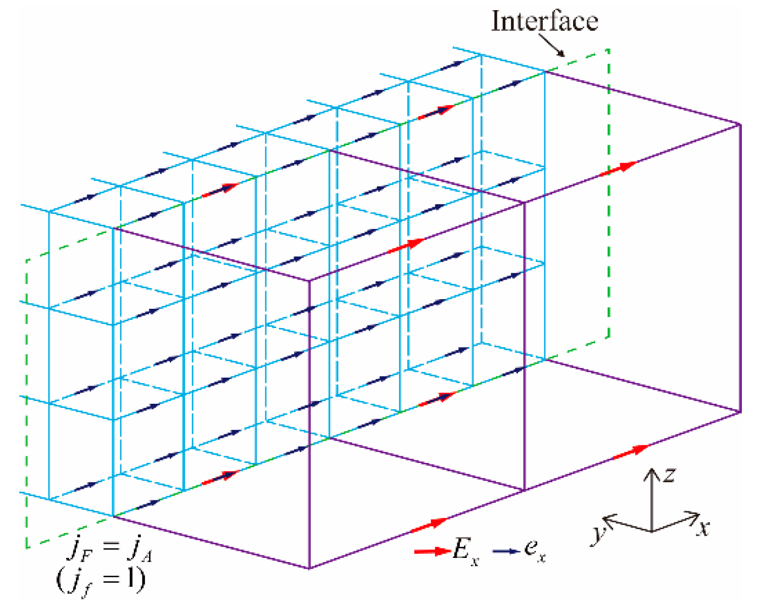
In this work, the hybrid computational scheme of multiscale grid is proposed by combining the traditional FDTD method with the LOD-FDTD method. The EM components in the coarse-grid region are numerically calculated through the traditional FDTD method, while the EM components in the fine-grid domain are numerically solved by the LOD-FDTD method (such as Equations (17) and (18)). Depending on the unconditional stability of the LOD-FDTD method, the fine-grid region could adopt the time step that meets the CFL stability conditions of the coarse-grid time step, therefore, the coarse-grid region only is required to be interpolated in space, not in time. The purpose of spatial interpolation is that the electric field value e of fine grid on the interface of coarse and fine grids cannot be solved iteratively by the LOD-FDTD method. As shown in Figure 1, the electric field value E of coarse grid on the interface needs to be interpolated to the electric field value e of fine grid on the interface so that the internal EM field components of fine grid domain could be solved collaboratively. In 3D computational space, there are six interfaces in the coarse and fine grid domains. For the convenience of description, we take the electric field value ex on the coarse and fine grid interface seen in Figure 1 as an example to introduce the relevant interpolation processing. Meanwhile, the similar method could be applied to other interfaces.
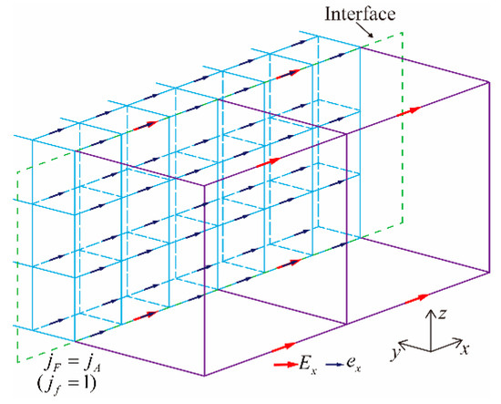
Figure 1.
3D interface between coarse and fine grids.
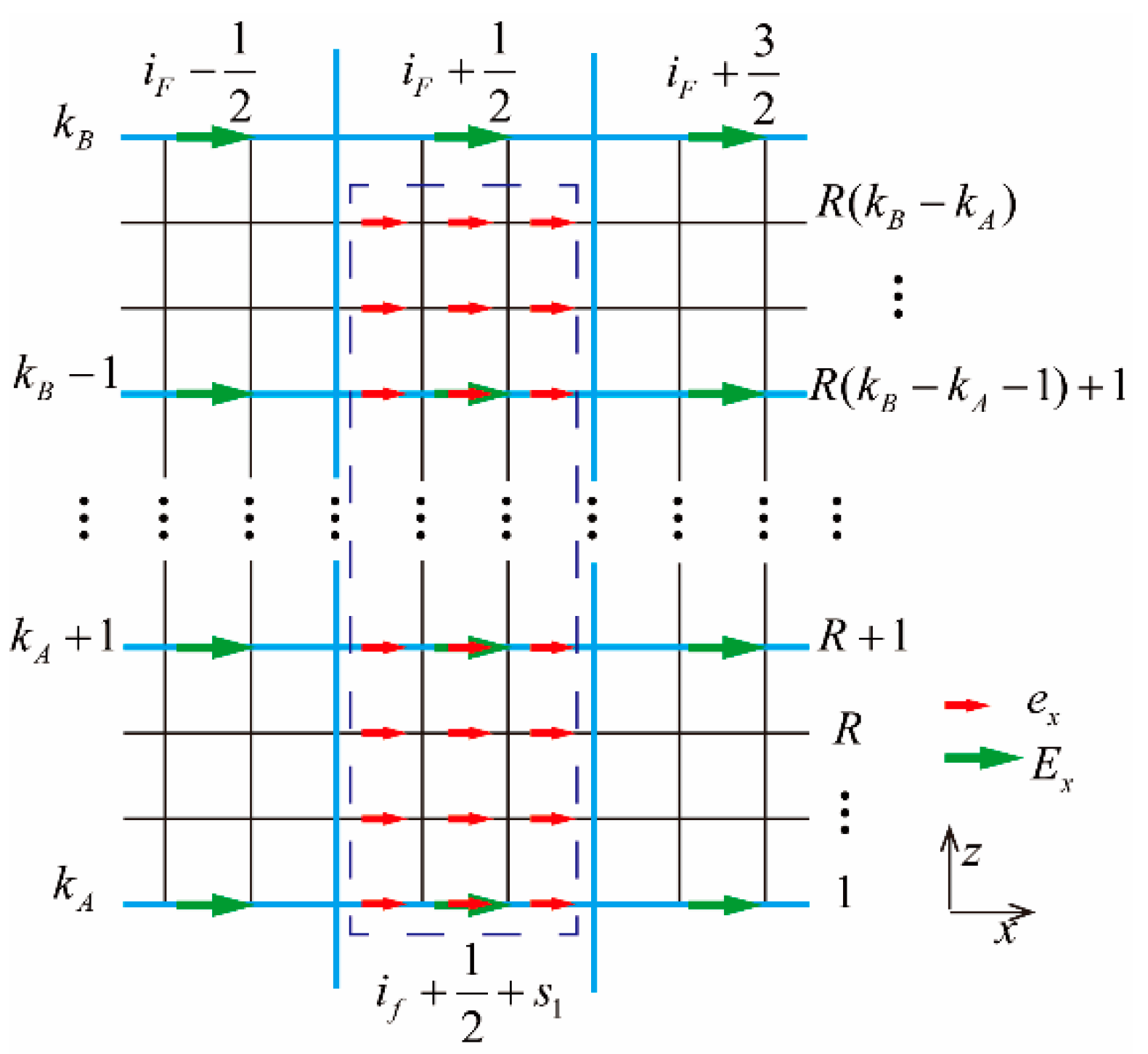
As shown in Figure 2, it is the diagram of electric field distribution between coarse and fine grids on the interface () of Figure 1, the subscript F is denoted as the coarse-grid coordinate, the f is defined as the fine-grid coordinate. Taking the interpolation processing of fine-grid electric field from to in the box of Figure 2 as an example, where is the positive integer, , R is the ratio between coarse and fine grids, is expressed as the grid coordinate () of the coarse grid along x direction on the interface. if is defined as the grid coordinate (if = R × (iF − iA). (iA, iB)) of the fine grid along x direction on the interface, (jA, jB), (kA, kB) are respectively the front and rear interfaces in the x, y, and z directions of coarse-grid domain. The spatial interpolation formulations shown below could be utilized to obtain the fine-grid electric fields from to in the box.
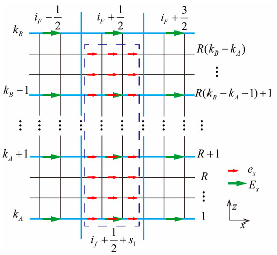
Figure 2.
Interpolation diagram of electric field ex on the interface.
When :
When :
where
It should be noted in Figure 2 that the ratio of the coarse- and fine-grid generation is the odd. Similarly, the case of the even ratio of coarse- and fine-grid generation could be obtained in the same way.
After adopting the spatial interpolation processing, the iterative formulations of electric field on the surface jf = 2 of fine-grid domain need to be modified, taking the equation (Equation (17)) in the moment of n + 1/2 as an example, we have
When :
when :
where is derived from Equations (19) and (20). s2 is defined as the positive integer, , is expressed as the grid coordinate () along z direction on the interface of coarse grid. kf is the grid coordinate () along z direction on the interface of fine grid.
After finishing the iteration of EM field components in the fine-grid region, The EM field components of coarse-grid domain in the fine-grid domain need to be interpolated in order that the EM information exchange between coarse and fine grids could be achieved. Taking x direction as an instance, we have
If R is the odd:
If R is the even:
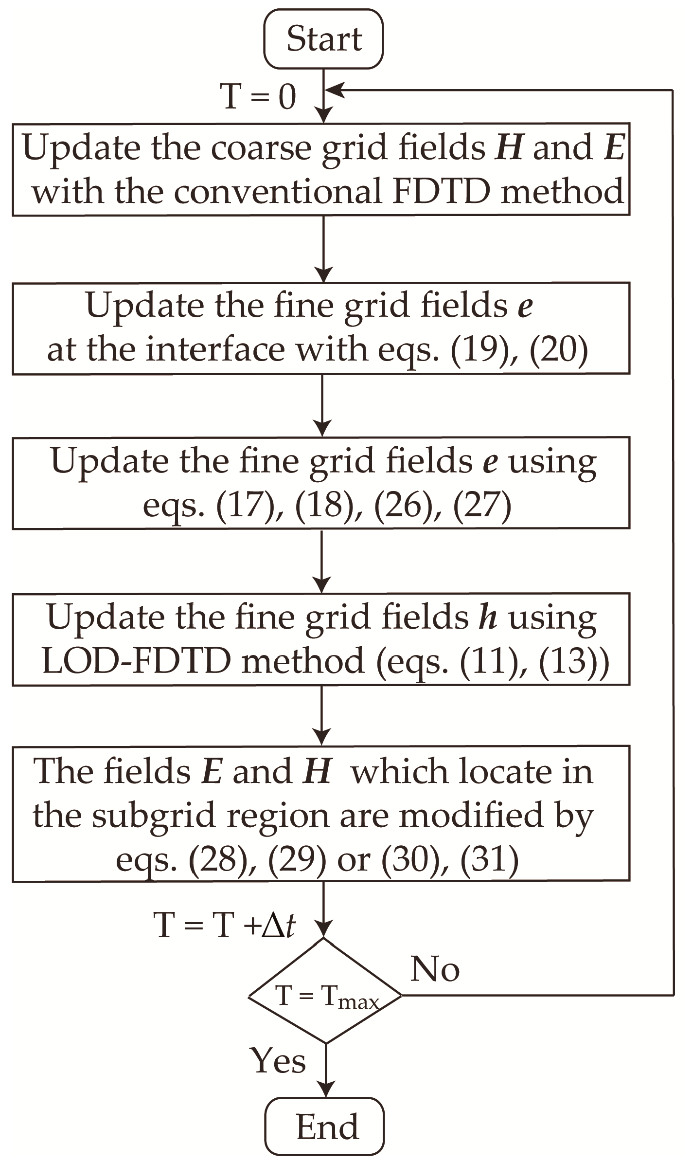
Finally, we present computational steps of the hybrid subgridding LOD-FDTD method (as shown in Figure 3), for instance, (1) Employing the FDTD method to solve the EM field values (E and H) in the coarse-grid domain; (2) the interpolation is carried out on the interface of fine-grid domain by using Equations (19) and (20) so as to obtain the electric field value in the fine-grid domain; (3) the electric field ex in the fine-grid domain could be solved by applying Equations (17), (18), (26) and (27) (a similar way could be carried out to achieve ey and ez in the fine-grid domain); (4) the magnetic field value h in the fine-grid domain could be solved by means of Equation (11) and Equation (13); (5) finally the EM field values in the coarse-grid domain are corrected by adopting Equations (28)–(31).
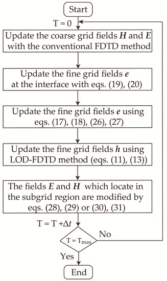
Figure 3.
Flowchart of hybrid subgridding LOD-FDTD method.
3. Results and Discussion
3.1. Rectangular Waveguide
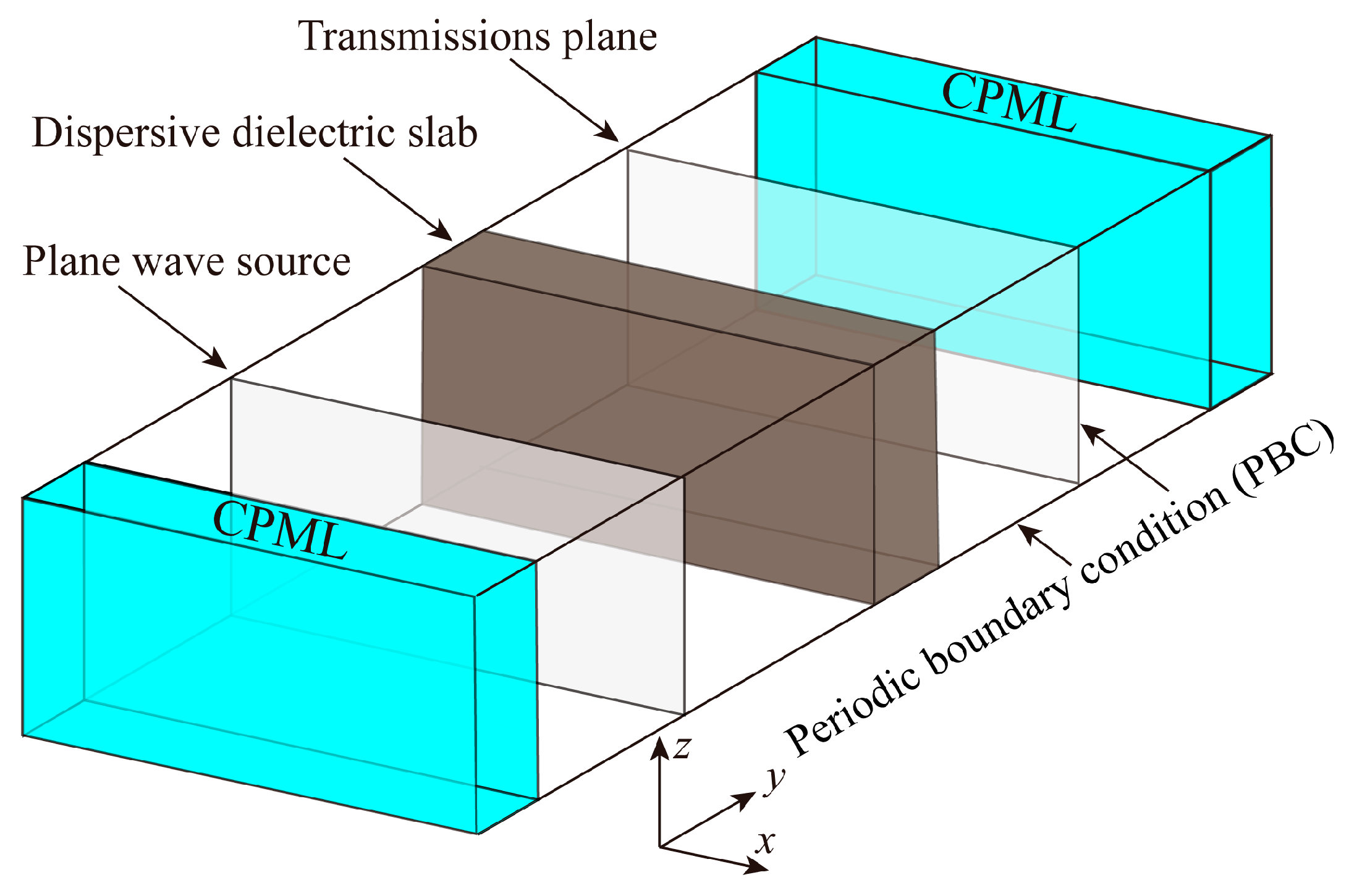
In order to demonstrate the accuracy of proposed ZT-LOD-FDTD method, a simulation model which has analytical solution is investigated [47]. As shown in Figure 4, a 3D rectangular waveguide model with a dispersive dielectric slab is considered, and the property of the dispersive dielectric slab can be described by the one-pole lossy Debye model. A plane wave with Gaussian pulse is performed and propagate along y-direction, and the parameters in the Gaussian function are set as Ts = 0.1 ns, t0 = 5 Ts. The convolutional PML (CPML) is loaded at both ends of the propagation direction, and the periodic boundary condition (PBC) is set at the x and z directions. The grid size is chosen as 0.1 mm in x, y and z direction, and the thickness of the slab is set as 0.2 mm, and the parameters of the soil ε∞ = 29.9, ∆ε1 = 18, τ1 = 43.6 fs, and σ = 0.54 S/m.
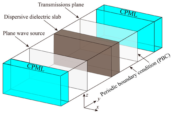
Figure 4.
Simulation configurations of the 3D rectangular waveguide.
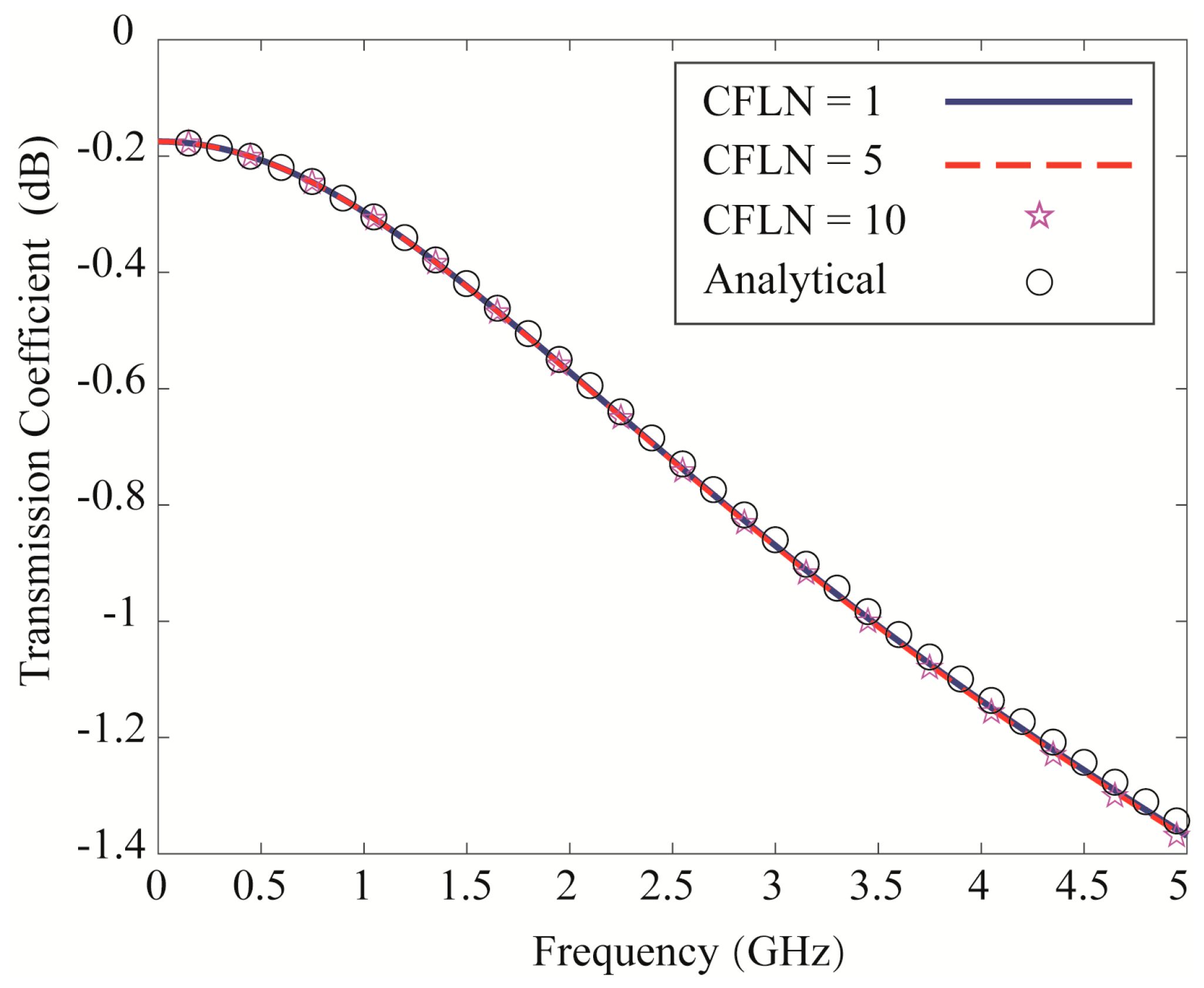
Figure 5 shows the transmission coefficients obtained by the ZT-LOD-FDTD method (CFLN = 1, 5, 10). For comparison, the result obtained by the analytical method is used as the benchmark. It is clearly shown that the results obtained by the ZT-LOD-FDTD method with different time steps are agreed with that of the analytical results, which testify the ZT-LOD-FDTD approach as an efficient technique to simulate Debye dispersive media.
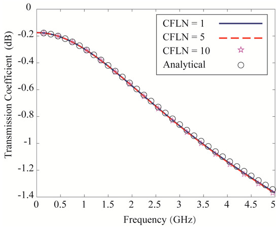
Figure 5.
Transmission coefficient calculated by the analytical method and the ZT−LOD−FDTD method (CFLN = 1, 5, 10, and CFLN = 1 means that the time step is chosen as the CFL limit of the conventional FDTD method).
With the purpose of validating the correctness and effectiveness of the proposed hybrid LOD-FDTD with subgridding scheme, three classical GPR scenarios are simulated by the proposed method. The simulation platform of the numerical examples in this work is: 32.0 GB RAM, Intel(R) Core(TM) i7-11700 CPU @ 3.80GHz. For truncating the physical domain, the CPML implementation based on Z-transform method is adopted. The underground detection targets comprise two EM structures: dielectric sphere and dielectric cylinder. In the free space, the transmitting and receiving antennas are respectively used as the excitation source point and the detection point, which are employed to transmit and receive detection signals. The excitation source in the time domain is defined as
where the centre frequency is 300 MHz, τ = 1.7/fc, the coefficient a1 = −0.493, a2 = 0.144, a3 = −0.01.
3.2. Dielectric Sphere
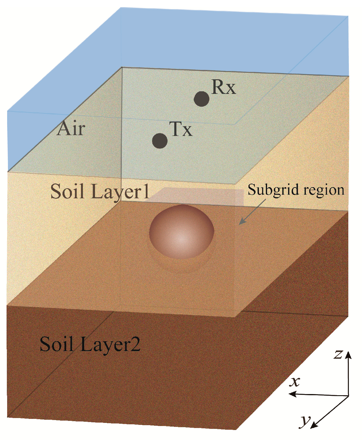
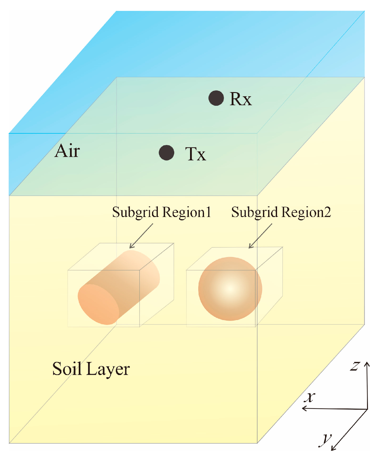
Considering the actual situation, the density, humidity and other properties of soil would vary due to its depth. As shown in Figure 6, the simulation domain in this example includes air, soil layer 1 and soil layer 2.
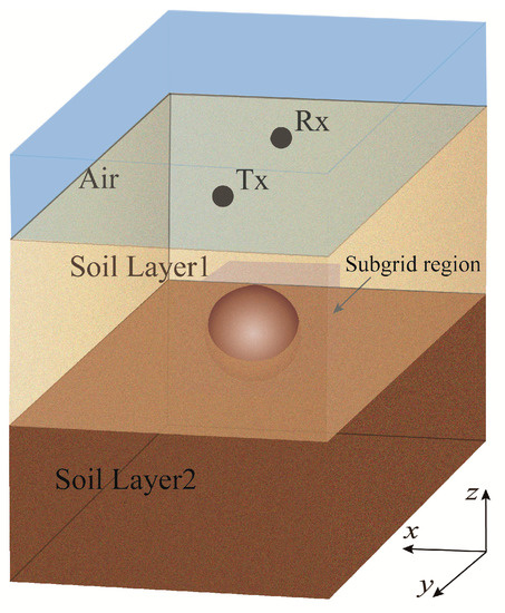
Figure 6.
The 3D model setup is a GPR system placed over a dielectric sphere buried in soil. Tx is the transmitting end, and Rx is the receiving end.
The detection target is a medium sphere whose upper and lower parts are located in these two soil media respectively. The dispersion property of soil is described by adopting the multi-level Debye model, and the parameters of the first-layer soil are ε∞ = 3.0, ∆ε1 = 0.10, ∆ε2 = 0.25, τ1 = 2.78 ns, τ2 = 0.113 ns, and σ = 0.415 × 10⁻³ S/m. ones of second-layer soil are ε∞ = 4.5, ∆ε1 = 2.10, ∆ε2 = 0.70, τ1 = 4.08 ns, τ2 = 0.261 ns, and σ = 1.11 × 10⁻³ S/m. The whole computational domain in size is 1.8 m by 1.8 m by 2.4 m in the x, y, and z directions. The spatial incremental size in the coarse-grid domain is set as Δx = Δy = Δz = 0.03 m, and the temporal incremental size in the coarse-grid domain is Δt = 0.0625 ns. The whole simulation domain occupies 60 × 60 × 80 Yee cells. The transmitting and receiving antennas are placed in the free space, and are 0.18 m far away from the ground, and the distance between transmitting and receiving antennas (Tx-Rx) is 0.45 m in the y direction. The subgridding domain in size is 0.3 m by 0.3 m by 0.3 m, the detection target is a dielectric sphere buried 0.3 m below the ground, with the relative dielectric constant of 30 and a radius of 0.12 m. To validate the correctness and effectiveness of the proposed LOD-FDTD method with subgridding scheme, the computational result of uniform FDTD method based on the fine grid (Δxf = Δyf = Δzf = 0.01 m) is viewed as the reference solution.
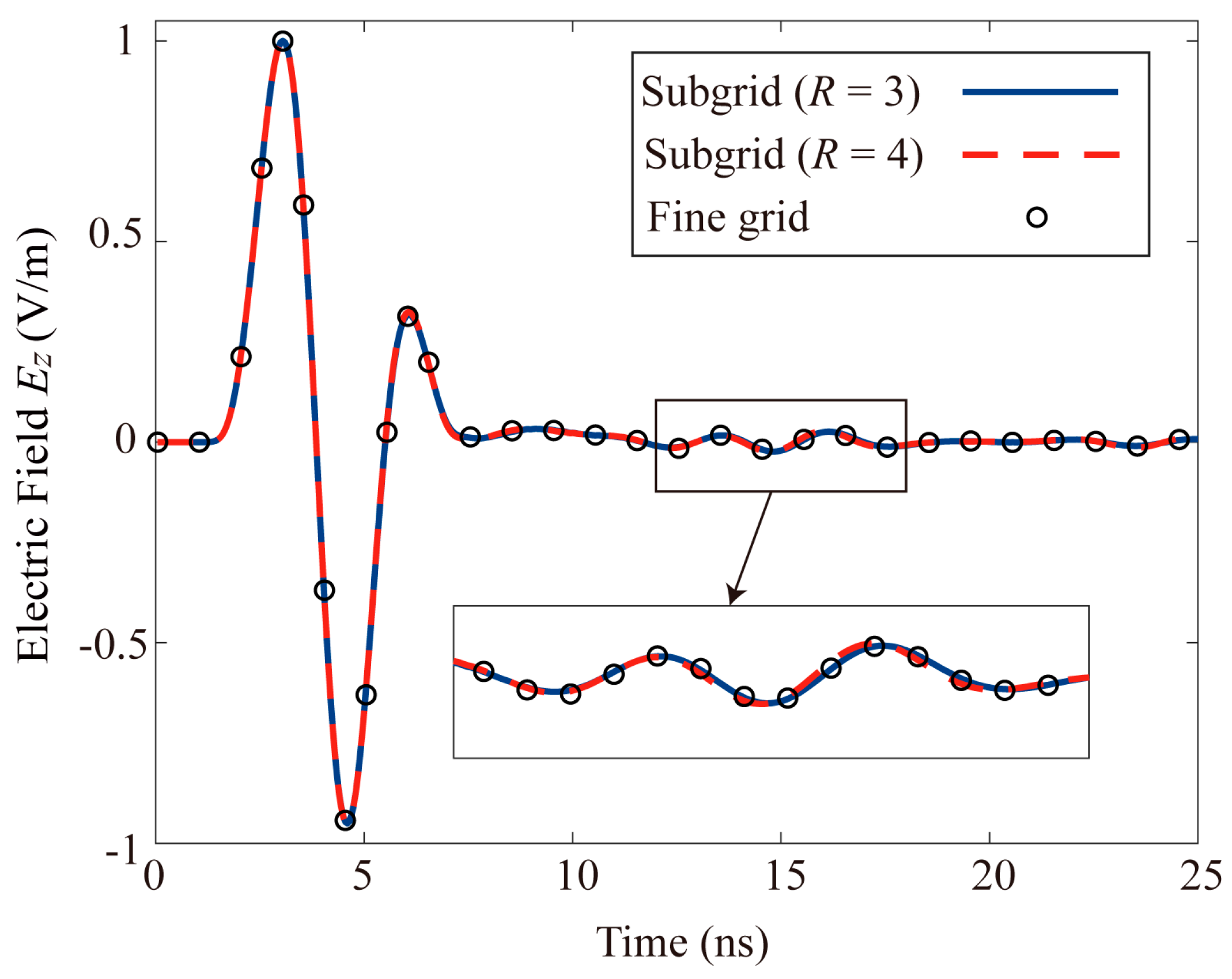
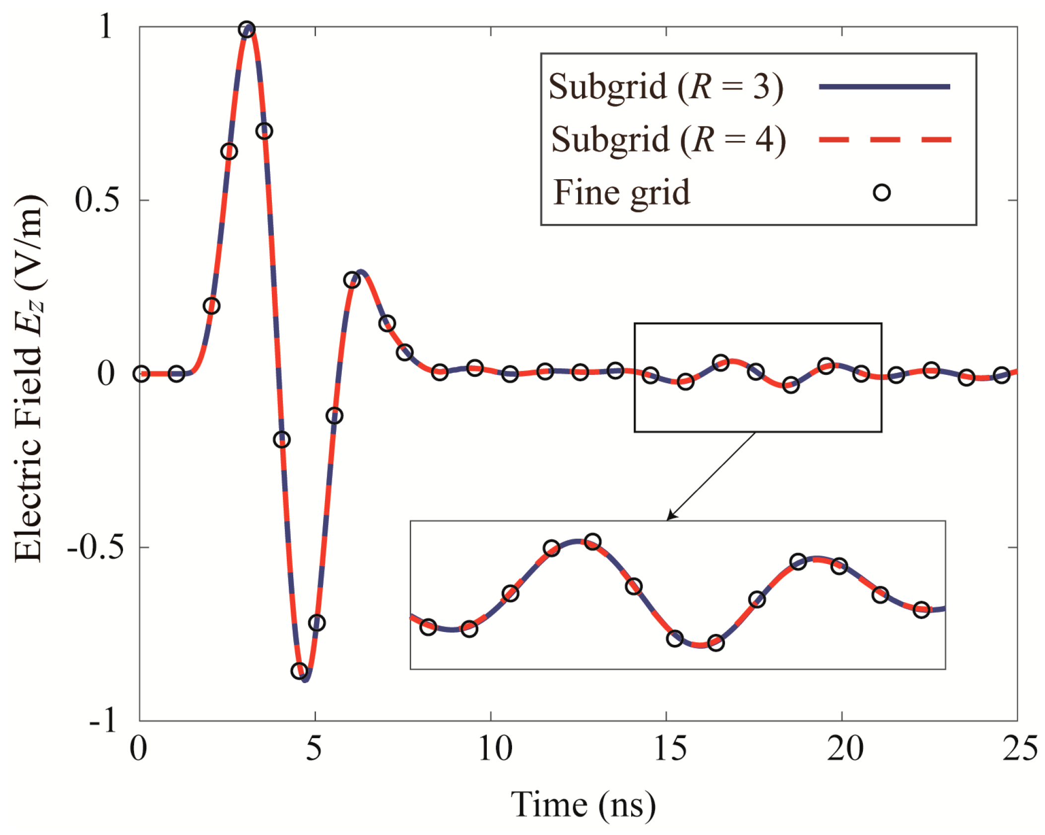
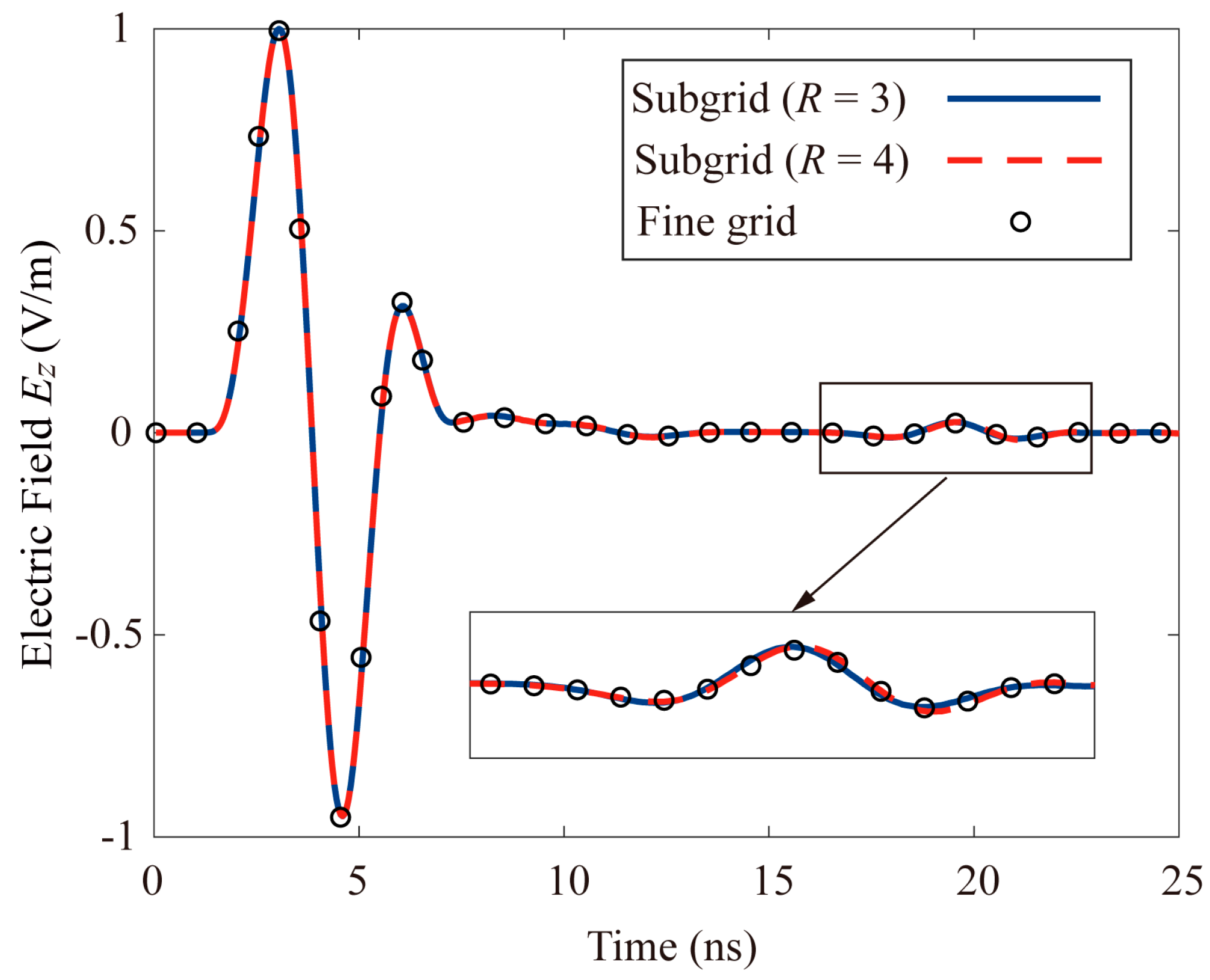
It shows the results of the hybrid LOD-FDTD with subgridding scheme by using two ratios of grid generation with 1:3 and 1:4 respectively, and the result of the uniform fine-grid FDTD method are illustrated in Figure 7. It could be found from the agreement of waveforms that the subgridding method proposed in this work is suitable for odd and even discretizations.
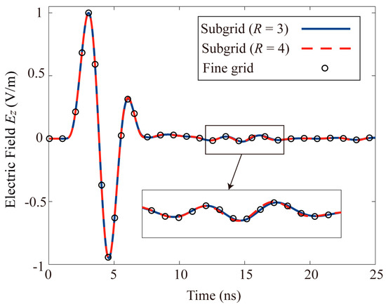
Figure 7.
Time−domain waveforms of Ez at the receiving antenna calculated by three methods.
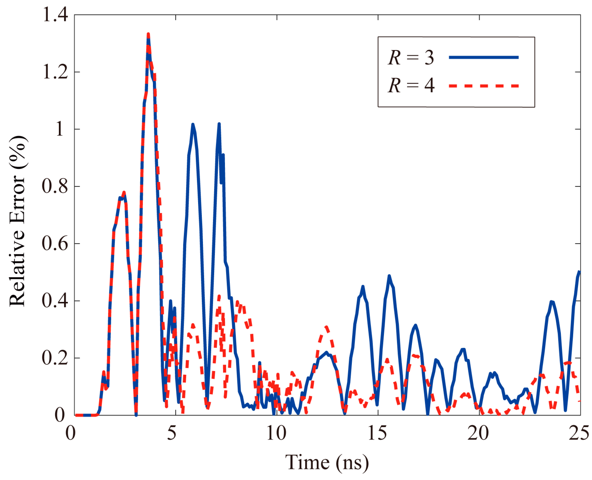
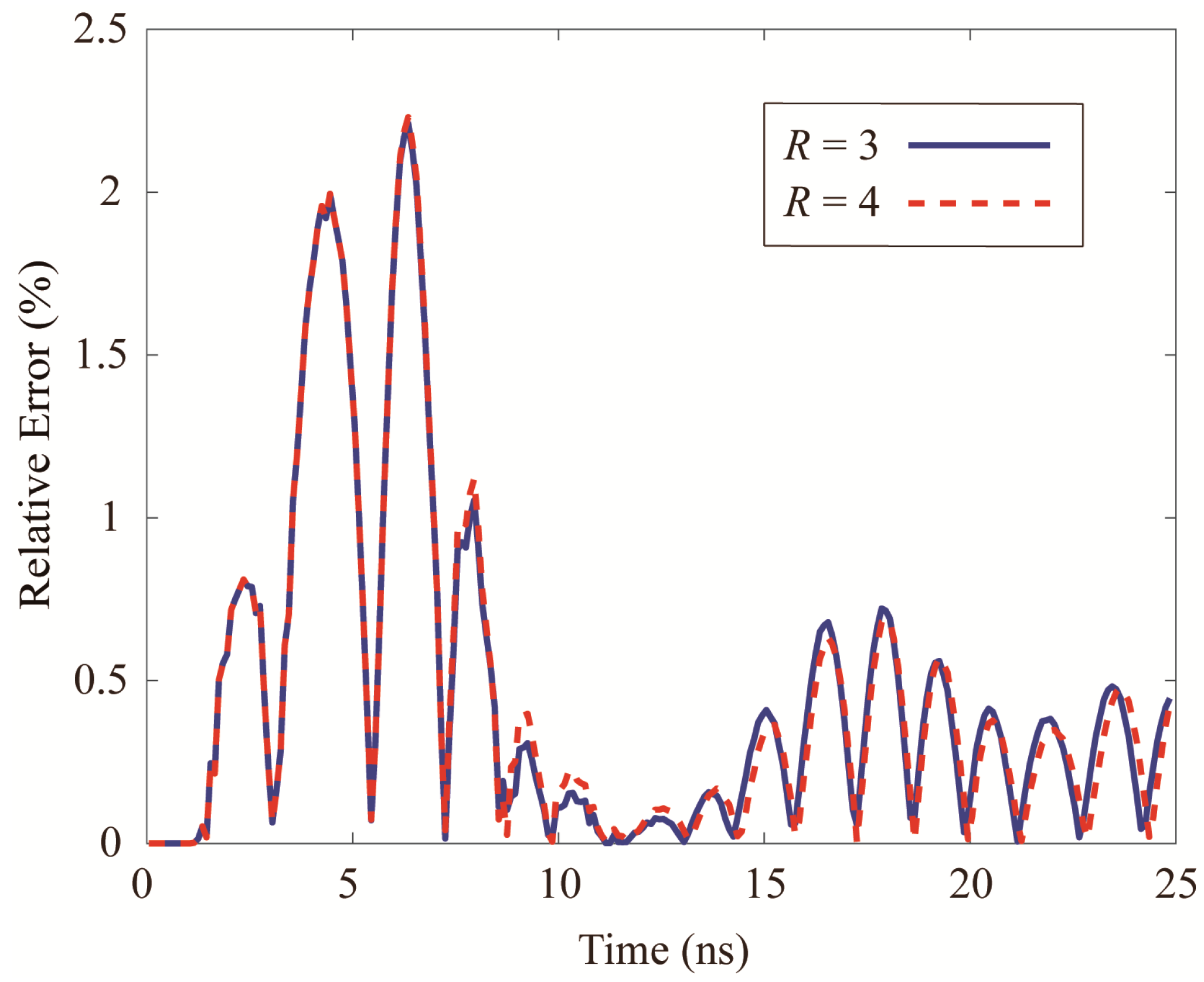
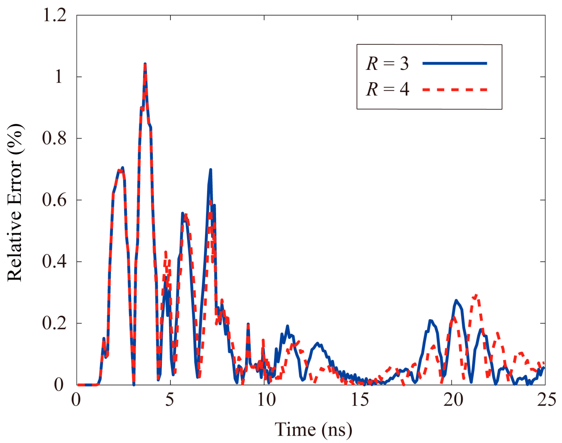
Besides, for quantitatively analysing the numerical error, Equation (33) is adopted to calculate the relative error of the hybrid subgridding LOD-FDTD method. As reflected in Figure 8, the relative errors generated by odd or even times are relatively small, and meanwhile as the meshing ratio increases, the numerical error decreases, which further verifies the high versatility of the proposed method. As a result, it could be observed that using a larger time step in the fine-grid domain would not have a great influence on the numerical dispersion difference.
where Ez is obtained at the Rx grid location.
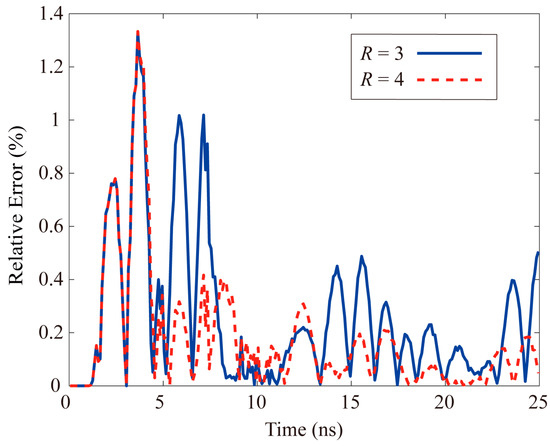
Figure 8.
Relative error of hybrid subgridding LOD−FDTD method.
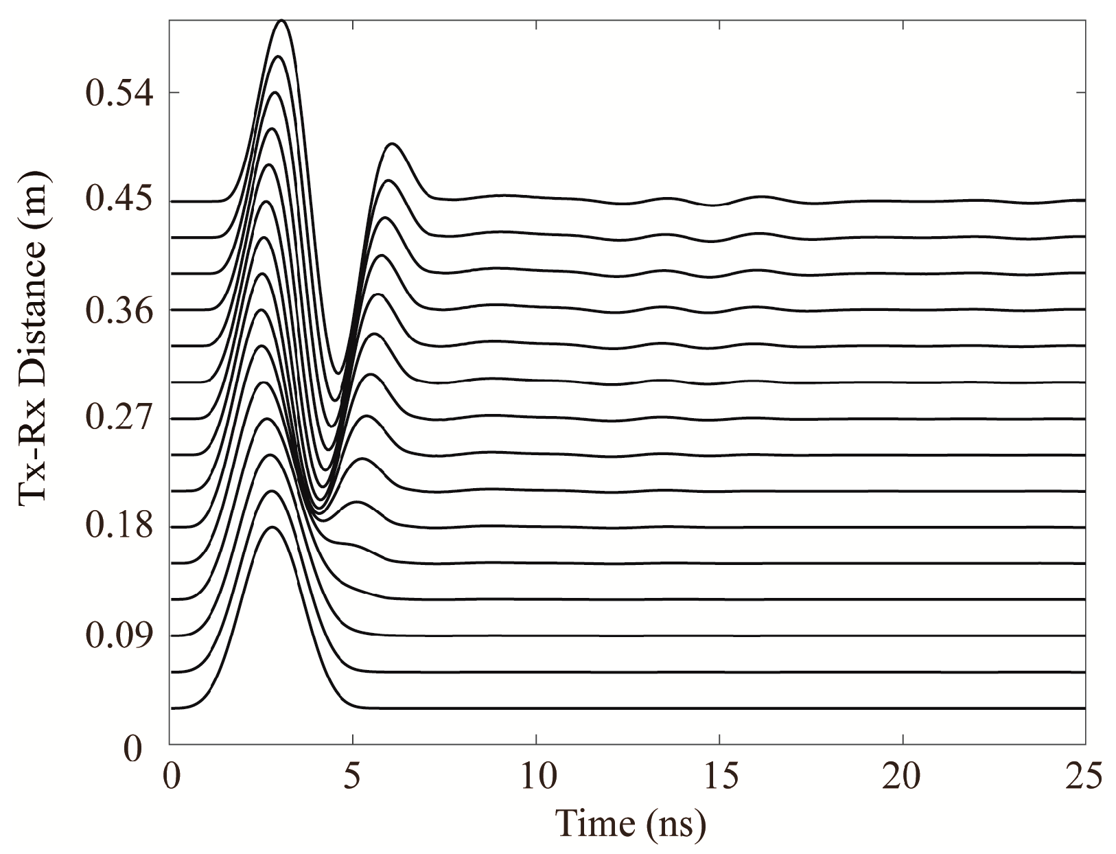
The received signal when the distance between the receiving antenna and the transmitting antenna changes from 0 m to 0.39 m are seen in Figure 9. Through the normalized time-domain waveform, it could be found that the amplitude of EM radiation scattered by the target and received by the receiving end would increase with the increase of Tx-Rx distance.
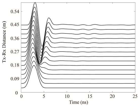
Figure 9.
Comparisons of time-domain waveforms for different distances of transmitting and receiving antennas.
Ultimately, Table 1 shows the memory occupation and CPU time of the two methods. It could be seen from Table 1 that the proposed hybrid subgridding LOD-FDTD method could substantially reduce the computational memory and CPU time.

Table 1.
Memory Cost (mb) and Execution Times (s) for Fine-Grid FDTD and Hybrid Subgrid Method.
3.3. Multi-Target Detection with Dielectric Cylinder and Dielectric Sphere
Considering the diversity of underground targets, the GPR scenario with multiple detection targets is simulated in the second case. In this example, both the sphere and the cylinder are placed in the same soil media.
As plotted in Figure 10, the entire domain presents the same characteristics with the Case A, the CPML we adopt is 10 layer thickness. The parameter of soil layer ε∞ = 3.2, ∆ε1 = 0.75, ∆ε2 = 0.3, τ1 = 2.71 ns, τ2 = 0.108 ns, σ = 1.11 × 10⁻³ S/m. These two subgridding domains in size are 0.3 m by 0.3 m by 0.3 m with these two detected targets are buried 0.3 m away from the ground surface. The distance between the centers of these two targets is 0.15 m in the x direction. The dielectric constant of sphere is , its radius is 0.12 m. Meanwhile, the dielectric constant of cylinder is , its radius and length are respectively 0.09 m and 0.24 m. To validate the correctness and effectiveness of the proposed hybrid subgridding LOD-FDTD method, the result obtained by using uniform FDTD method with the fine-grid discretization is considered as the reference solution.
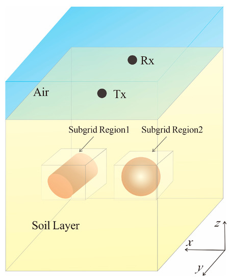
Figure 10.
3D classical GPR system for detecting multiple targets, Tx and Rx are respectively the transmitting and receiving ends.
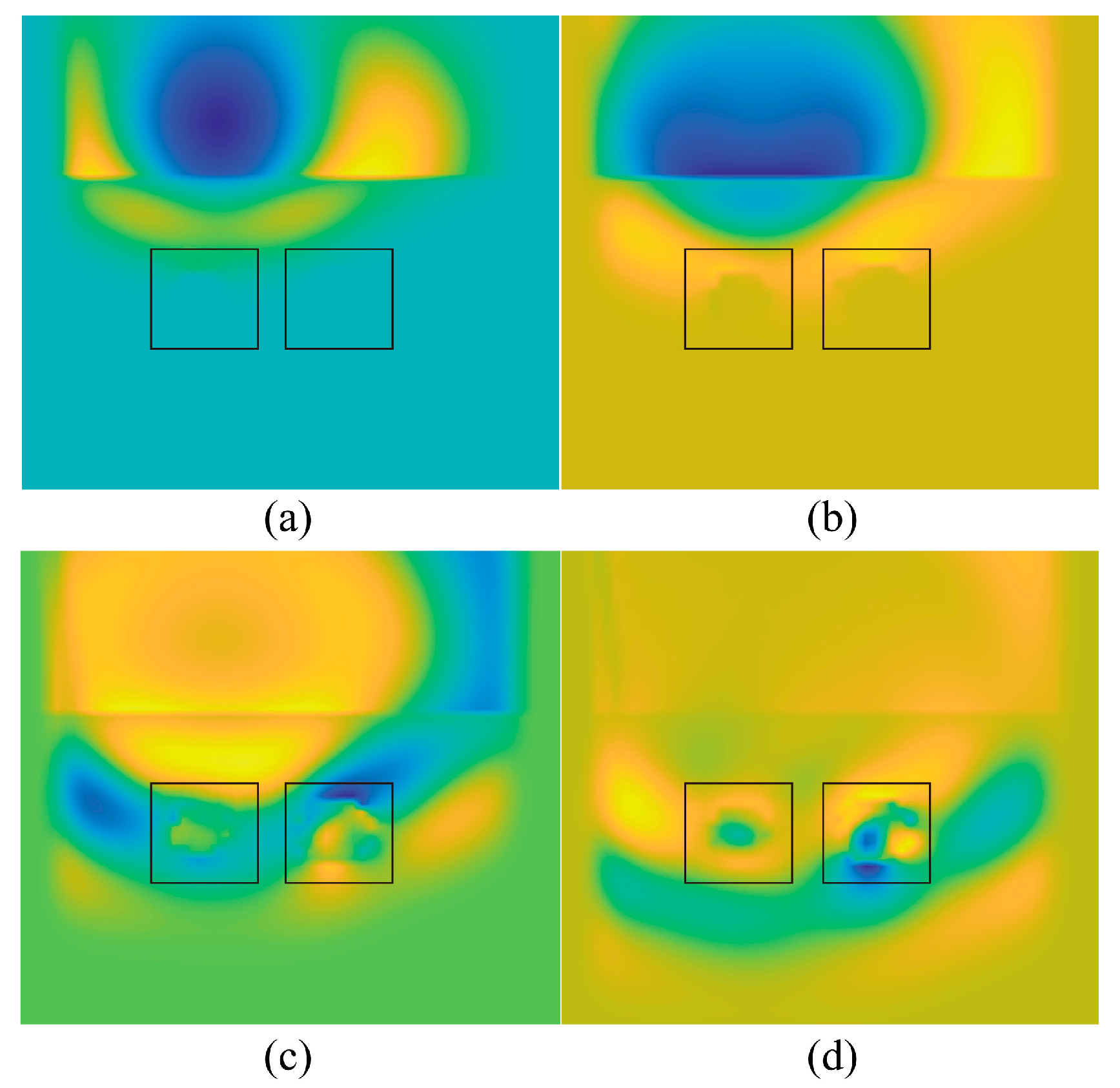
As reflected in Figure 11, the time-domain waveforms are shown at the receiving antenna calculated by the hybrid LOD-FDTD method with different meshing ratios and the traditional FDTD method with a uniform fine-grid discretization. Good consistency of the numerical results between them is observed. Furthermore, Figure 12 reflects the calculation error between the hybrid LOD-FDTD and the reference solution in the multi-target detecting scenario. As a result, the aforementioned result verifies that the recommended approach is correct. As illustrated in Figure 13, the transient changes of the electric field at different moments are extracted through the electric field snapshot. The transition from the coarse- to the fine-grid domain could be smoothed by the electric field, which reflects the stability and correctness of the coarse- and fine-grid field value exchange of the proposed hybrid subgridding LOD-FDTD method.
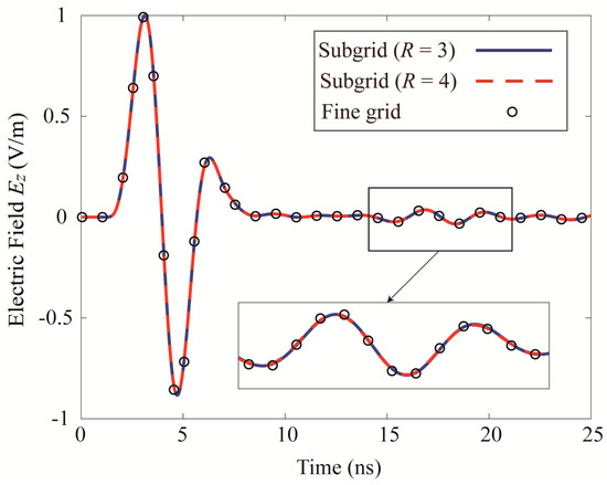
Figure 11.
Time−domain waveforms of the Ez (cylinder and sphere) at the receiving antenna are calculated by three methods respectively.
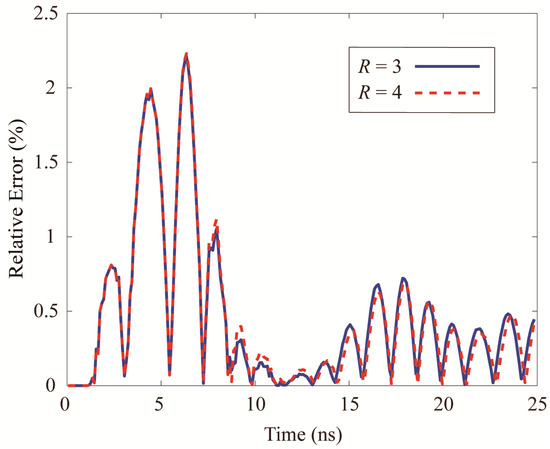
Figure 12.
Relative errors of hybrid subgridding LOD-FDTD method with different proportions (cylinder and sphere).
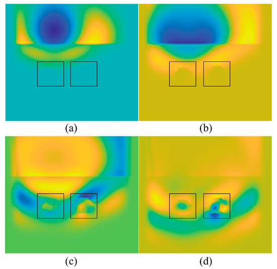
Figure 13.
Time snapshots of Ez amplitude calculated by hybrid subgridding LOD-FDTD method in multi-target scenario (a) snapshot 1. (b) snapshot 2. (c) snapshot 3. (d) snapshot 4.
Table 2 shows the memory occupation and CPU time of the two methods. It could be seen from Table 2 that the proposed hybrid subgridding LOD-FDTD method could greatly reduce the computational memory and CPU time.

Table 2.
Memory Cost (MB) and Execution Time (s) Consumption for Fine-Grid FDTD and Hybrid Subgridding Methods for Case 3.3.
3.4. Dispersive Sphere
In the practical GPR detection, we often encounter the detection target whose dielectric coefficient is related to the frequency. Therefore, this example would simulate this kind of GPR scenario, replacing the dielectric sphere in Case A with the dispersive dielectric sphere in the same computational domain, and only considering monolayer soil. The dispersive dielectric sphere is simulated by the multi-level Debye model, its parameters are ε∞ = 168.0151, ∆ε1 = 34.2007, ∆ε2 = 12.0813, τ1 = 13.56 ms, τ2 = 0.108 ms.
As seen in Figure 14, the time-domain waveforms of the electric field of the receiving antenna are respectively calculated by employing the hybrid subgridding LOD-FDTD method with the coarse-to-fine-grid ratio of 1:3 and 1:4 and the uniform fine-grid FDTD method. Taking the calculation result of uniform fine-grid FDTD as the reference solution, as shown in Figure 15, the errors of the two meshing methods are quantitatively analyzed. Besides, as we could observe that the time-domain waveforms are in the good consistency and the relative error is small, which verifies the correctness of the proposed method. Finally, as shown in Table 3, these three methods we proposed could effectively decrease the computational memory and CPU time.
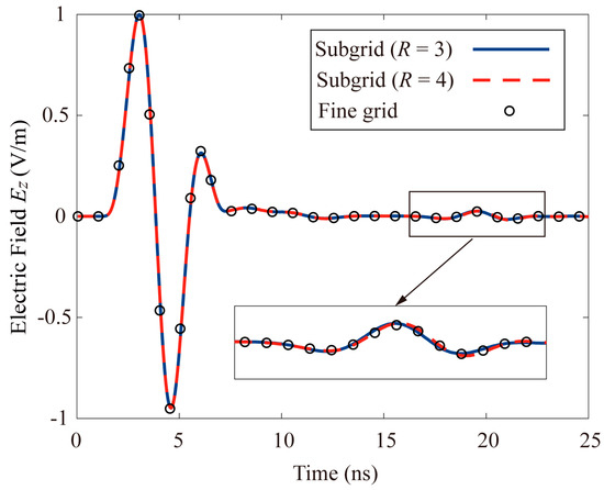
Figure 14.
Time−domain waveforms of the Ez (dispersive sphere) at the receiving antenna are calculated by three methods respectively.
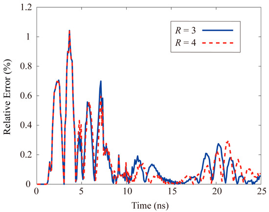
Figure 15.
Relative errors of hybrid subgridding LOD-FDTD method with different proportions (dispersive sphere).

Table 3.
Memory Cost (MB) and Execution Times (s) for Hybrid Subgridding and Fine-Grid FDTD Methods for Case 3.4.
4. Conclusions and Future Prospects
The explicit characteristic of regular FDTD method makes it difficult to trade off the accuracy and efficiency in the GPR scene simulation. In the GPR system, the multiscale characteristics of the EM structure and the amplitude of the EM field of the detection target change dramatically. With a view to ensuring the accuracy of numerical calculation, in general a smaller spatial incremental is adopted for grid generation, which greatly reduces the advantage of FDTD method in the GPR application. Hence the hybrid subgridding LOD-FDTD method is proposed in this work. The unconditionally stable LOD-FDTD method is adopted in the fine-grid domain, and the conventional FDTD method is used in other coarse-grid domains. This multiscale hybrid subgridding method could effectively simulate 3D GPR problems. Generally speaking, the main contributions of this work are as follows: (1) the LOD-FDTD method based on Z-transform technique is proposed to simulate multi-level Debye dispersive media, which is more direct in numerical realization than the convolutional method and auxiliary differential equation (ADE) method; (2) A hybrid subgridding technique combining the LOD-FDTD method and the traditional FDTD method is proposed. The unconditional stability of LOD-FDTD method enables the whole calculation domain to employ a uniform coarse-grid time step for numerical calculation. Therefore, only spatial interpolation processing is required, which reduces the application difficulty of subgridding method; (3) the subgridding method proposed in this work could divide the coarse grid into fine grids at any scale in the computational domain, which shows high versatility. Finally, three GPR scenarios are simulated to verify the correctness of the proposed method. Through numerical simulation, it can be found that the GPR system simulated by the proposed hybrid subgrid LOD-FDTD technology is about 5–10 times of the traditional FDTD method. If the GPR system needs more refined grid division in local areas of the simulation space, the computational advantages will be more obvious. The multi-scale subgrid technology based on unconditionally stable FDTD method is a research hotspot in the field of GPR forward simulation. The method proposed in this paper has a certain guiding role in the development of this field, and also provides research ideas for the development of other efficient GPR forward simulation methods.
Author Contributions
Conceptualization, G.X. and N.F.; methodology, N.F., G.X. and Z.H.; formal analysis, M.F., Z.S., G.H. and Z.H.; writing–original draft preparation, N.F., G.X., M.F., Z.S. and G.H.; writing–review and editing, N.F., G.X. and Z.H. All authors have read and agreed to the published version of the manuscript.
Funding
This research is funded by the National Nature Science Foundation of China under Grant 62201003, 62271001, 61901274, U20A20164, and 61901001, by the Shenzhen Science and Technology Innovation Committee under Grant JCYJ20190808141818890, by the Guangdong Natural Science Foundation under Grant 2020A1515011475.
Institutional Review Board Statement
Not applicable.
Informed Consent Statement
Not applicable.
Data Availability Statement
Not applicable.
Acknowledgments
We would like to thank William T. Joines of Duke University in USA for language check and spending his valuable time polishing our manuscript.
Conflicts of Interest
The authors declare no conflict of interest.
References
- Jonard, F.; André, F.; Pinel, N.; Warren, C.; Vereecken, H.; Lambot, S. Modeling of multilayered media Green’s functions with rough interfaces. IEEE Trans. Geosci. Remote Sens. 2019, 57, 7671–7681. [Google Scholar] [CrossRef]
- Harry, M. Ground Penetrating Radar Theory and Applications; Elsevier: Amsterdam, The Netherlands, 2008. [Google Scholar]
- Jaufer, R.M.; Ihamouten, A.; Goyat, Y.; Todkar, S.S.; Guilbert, D.; Assaf, A.; Derobert, X. A preliminary numerical study to compare the physical method and machine learning methods applied to GPR data for underground utility network characterization. Remote Sens. 2022, 14, 1047. [Google Scholar] [CrossRef]
- Shangguan, P.; Al-Qadi, I.L. Calibration of FDTD simulation of GPR signal for asphalt pavement compaction monitoring. IEEE Trans. Geosci. Remote Sens. 2014, 53, 1538–1548. [Google Scholar] [CrossRef]
- Giannakis, I.; Giannopoulos, A.; Warren, C. A machine learning-based fast-forward solver for ground penetrating radar with application to full-waveform inversion. IEEE Trans. Geosci. Remote Sens. 2019, 57, 4417–4426. [Google Scholar] [CrossRef]
- Stadler, S.; Igel, J. Developing realistic FDTD GPR antenna surrogates by means of particle swarm optimization. IEEE Trans. Antennas Propag. 2022, 70, 4259–4272. [Google Scholar] [CrossRef]
- Van der Kruk, J.; Diamanti, N.; Giannopoulos, A.; Vereecken, H. Inversion of dispersive GPR pulse propagation in waveguides with heterogeneities and rough and dipping interfaces. J. Appl. Geophys. 2012, 81, 88–96. [Google Scholar] [CrossRef]
- Koyan, P.; Tronicke, J. 3D modeling of ground-penetrating radar data across a realistic sedimentary model. Comput. Geosci. 2020, 137, 104422. [Google Scholar] [CrossRef]
- Liu, L.; Li, Z.; Arcone, S.; Fu, L.; Qiang, H. Radar wave scattering loss in a densely packed discrete random medium: Numerical modeling of a box-of-boulders experiment in the Mie regime. J. Appl. Geophys. 2013, 99, 68–75. [Google Scholar] [CrossRef]
- Meles, G.A.; Greenhalgh, S.A.; Green, A.G.; Maurer, H.; van der Kruk, J. GPR full-waveform sensitivity and resolution analysis using an FDTD adjoint method. IEEE Trans. Geosci. Remote Sens. 2011, 50, 1881–1896. [Google Scholar] [CrossRef]
- Loewer, M.; Igel, J.; Wagner, N. Spectral decomposition of soil electrical and dielectric losses and prediction of in situ GPR performance. IEEE J. Sel. Top. Appl. Earth Obs. Remote Sens. 2015, 9, 212–220. [Google Scholar] [CrossRef]
- Giannakis, I.; Giannopoulos, A.; Warren, C. A realistic FDTD numerical modeling framework of ground penetrating radar for landmine detection. IEEE J. Sel. Top. Appl. Earth Obs. Remote Sens. 2015, 9, 37–51. [Google Scholar] [CrossRef]
- Yang, M.; Fang, H.; Wang, F.; Jia, H.; Lei, J.; Zhang, D. The three dimension first-order symplectic partitioned Runge-Kutta scheme simulation for GPR wave propagation in pavement structure. IEEE Access 2019, 7, 151705–151712. [Google Scholar] [CrossRef]
- Liao, D.H.; Dogaru, T. Full-wave characterization of rough terrain surface scattering for forward-looking radar applications. IEEE Trans. Antennas Propag. 2012, 60, 3853–3866. [Google Scholar] [CrossRef]
- Wu, P.; Xie, Y.; Jiang, H.; Natsuki, T. Modeling of bandpass GPR problem by HIE procedure with enhanced absorption. IEEE Geosci. Remote Sens. Lett. 2021, 19, 1–5. [Google Scholar] [CrossRef]
- Natsui, M.; Ametani, A.; Mahseredjian, J.; Motoyama, H. Earth current and GPR distributions due to lightning and effect of a distribution line. IEEE Trans. Electromagn. Compat. 2019, 62, 2119–2127. [Google Scholar] [CrossRef]
- Yee, K.S. Numerical solution of initial boundary value problems involving Maxwell’s equations in isotropic media. IEEE Trans. Antennas Propag. 1966, 14, 302–307. [Google Scholar]
- Taflove, A.; Hagness, S.C.; Piket-May, M. Computational electromagnetics: The finite-difference time-domain method. Electr. Eng. Handb. 2005, 3, 629–670. [Google Scholar]
- Bekmambetova, F.; Triverio, P. A dissipation theory for potentials-based FDTD for lossless Inhomogeneous media. IEEE Antennas Wirel. Propag. Lett. 2021, 21, 486–490. [Google Scholar] [CrossRef]
- Al-Jabr, A.A.; Alsunaidi, M.A.; Ng, T.; Ooi, B.S. A simple FDTD algorithm for simulating EM-wave propagation in general dispersive anisotropic material. IEEE Trans. Antennas Propag. 2012, 61, 1321–1326. [Google Scholar] [CrossRef]
- Luebbers, R.; Hunsberger, F.P.; Kunz, K.; Standler, R.B.; Schneider, M. A frequency-dependent finite-difference time-domain formulation for dispersive materials. IEEE Trans. Electromagn. Compat. 1990, 32, 222–227. [Google Scholar] [CrossRef]
- Joseph, R.M.; Hagness, S.C.; Taflove, A. Direct time integration of Maxwell’s equations in linear dispersive media with absorption for scattering and propagation of femtosecond electromagnetic pulses. Opt. Lett. 1991, 16, 1412–1414. [Google Scholar] [CrossRef]
- Warren, C.; Giannopoulos, A.; Giannopoulos, I. gprMax: Open source software to simulate electromagnetic wave propagation for Ground Penetrating Radar. Comput. Phys. Commun. 2016, 209, 163–170. [Google Scholar] [CrossRef]
- Lin, C.; Wang, X.; Li, Y.; Zhang, F.; Xu, Z.; Du, Y. Forward modelling and GPR imaging in leakage detection and grouting evaluation in tunnel lining. KSCE J. Civ. Eng. 2020, 24, 278–294. [Google Scholar] [CrossRef]
- Shaari, A.; Ahmad, R.S.; Chew, T.H. Effects of antenna-target polarization and target-medium dielectric contrast on GPR signal from non-metal pipes using FDTD simulation. NDT E Int. 2010, 43, 403–408. [Google Scholar] [CrossRef]
- Xie, G.; Huang, Z.; Fang, M.; Wei, E.I. Simulating Maxwell–Schrödinger equations by high-order symplectic FDTD algorithm. IEEE J. Multiscale Multiphysics Comput. Tech. 2019, 4, 143–151. [Google Scholar] [CrossRef]
- Sha, W.; Huang, Z.; Wu, X.; Chen, M. Application of the symplectic finite-difference time-domain scheme to electromagnetic simulation. J. Comput. Phys. 2007, 225, 33–50. [Google Scholar] [CrossRef]
- Xie, G.; Huang, Z.; Fang, M.; Wu, X. A unified 3-D ADI-FDTD algorithm with one-step leapfrog approach for modeling frequency-dependent dispersive media. Int. J. Numer. Model. Electron. Netw. Devices Fields 2020, 33, e2666. [Google Scholar] [CrossRef]
- Chen, J.; Li, J.; Liu, Q.H. Analyzing graphene-based absorber by using the WCS-FDTD method. IEEE Trans. Microw. Theory Tech. 2017, 65, 3689–3696. [Google Scholar] [CrossRef]
- Yan, J.; Jiao, D. An unsymmetric FDTD subgridding algorithm with unconditional stability. IEEE Trans. Antennas Propag. 2018, 66, 4137–4150. [Google Scholar] [CrossRef]
- Kuo, C.W.; Kuo, C.M. Finite-difference time-domain analysis of the shielding effectiveness of metallic enclosures with apertures using a novel subgridding algorithm. IEEE Trans. Electromagn. Compat. 2016, 58, 1595–1601. [Google Scholar] [CrossRef]
- Ye, Z.; Liao, C.; Xiong, X.; Zhang, M. A novel FDTD subgridding method with improved separated temporal and spatial subgridding interfaces. IEEE Antennas Wirel. Propag. Lett. 2016, 16, 1011–1015. [Google Scholar] [CrossRef]
- Kulas, L.; Mrozowski, M. Low-reflection subgridding. IEEE Trans. Microw. Theory Tech. 2005, 53, 1587–1592. [Google Scholar] [CrossRef]
- Ye, Z.; Liao, X.; Zhang, J. A novel three-dimensional FDTD subgridding method for the coupling analysis of shielded cavity excited by ambient wave. IEEE Trans. Electromagn. Compat. 2019, 62, 2441–2449. [Google Scholar] [CrossRef]
- Xiao, K.; Pommerenke, D.J.; Drewniak, J.L. A three-dimensional FDTD subgridding algorithm with separated temporal and spatial interfaces and related stability analysis. IEEE Trans. Antennas Propag. 2007, 55, 1981–1990. [Google Scholar] [CrossRef]
- Mai, H.X.; Chen, J.; Zhang, A. A hybrid algorithm based on FDTD and HIE-FDTD methods for simulating shielding enclosure. IEEE Trans. Electromagn. Compat. 2017, 60, 1393–1399. [Google Scholar] [CrossRef]
- Wang, B.Z.; Wang, Y.; Yu, W.; Mittra, R. A hybrid 2-D ADI-FDTD subgridding scheme for modeling on-chip interconnects. IEEE Trans. Adv. Packag. 2001, 24, 528–533. [Google Scholar] [CrossRef]
- Ahmed, I.; Chen, Z. A hybrid ADI-FDTD subgridding scheme for efficient electromagnetic computation. Int. J. Numer. Model. Electron. Netw. Devices Fields 2004, 17, 237–249. [Google Scholar] [CrossRef]
- Wei, X.; Shao, W.; Wang, X.H. Hybrid sub-gridded time-domain method for ground penetrating radar simulations including dispersive materials. IEEE Access 2018, 6, 15777–15786. [Google Scholar] [CrossRef]
- Wei, X.K.; Zhang, X.; Diamanti, N.; Shao, W.; Sarris, C.D. Subgridded FDTD modeling of ground penetrating radar scenarios beyond the courant stability limit. IEEE Trans. Geosci. Remote Sens. 2017, 55, 7189–7198. [Google Scholar] [CrossRef]
- Shibayama, J.; Nomura, A.; Ando, R.; Tamauchi, J.; Nakano, H. A frequency-dependent LOD-FDTD method and its application to the analyses of plasmonic waveguide devices. IEEE J. Quantum Electron. 2009, 46, 40–49. [Google Scholar] [CrossRef]
- Tan, E. Unconditionally stable LOD–FDTD method for 3-D Maxwell’s equations. IEEE Microw. Wirel. Compon. Lett. 2007, 17, 85–87. [Google Scholar] [CrossRef]
- Liang, T.; Shao, W.; Wei, X.; Liang, M.S. Hybrid sub-gridding ADE–FDTD method of modeling periodic metallic nanoparticle arrays. Chin. Phys. B 2018, 27, 100204. [Google Scholar] [CrossRef]
- Prokopidis, K.; Zografopoulos, D. Modeling plasmonic structures using LOD-FDTD methods with accurate dispersion models of metals at optical wavelengths. J. Lightwave Technol. 2016, 35, 193–200. [Google Scholar] [CrossRef]
- Sullivan, D. Z-transform theory and the FDTD method. IEEE Trans. Antennas Propag. 1996, 44, 28–34. [Google Scholar] [CrossRef]
- Jiang, H.; Cui, T.; Wu, L.; Bo, X.C.; Wu, H.T. Efficient implementations of SC-PML for arbitrary media using DSP techniques. IEEE Trans. Electromagn. Compat. 2018, 61, 962–965. [Google Scholar] [CrossRef]
- Tekbas, K.; Costen, F.; Bérenger, J.P.; Himeno, R.; Yokota, H. Subcell modeling of frequency-dependent thin layers in the FDTD method. IEEE Trans. Antennas Propag. 2017, 65, 278–286. [Google Scholar] [CrossRef]
Publisher’s Note: MDPI stays neutral with regard to jurisdictional claims in published maps and institutional affiliations. |
© 2022 by the authors. Licensee MDPI, Basel, Switzerland. This article is an open access article distributed under the terms and conditions of the Creative Commons Attribution (CC BY) license (https://creativecommons.org/licenses/by/4.0/).

