True2 Orthoimage Map Generation
Abstract
:1. Introduction
2. Related Works
3. Principles of True2 Orthoimage Map (T2OM) Generation
- (1)
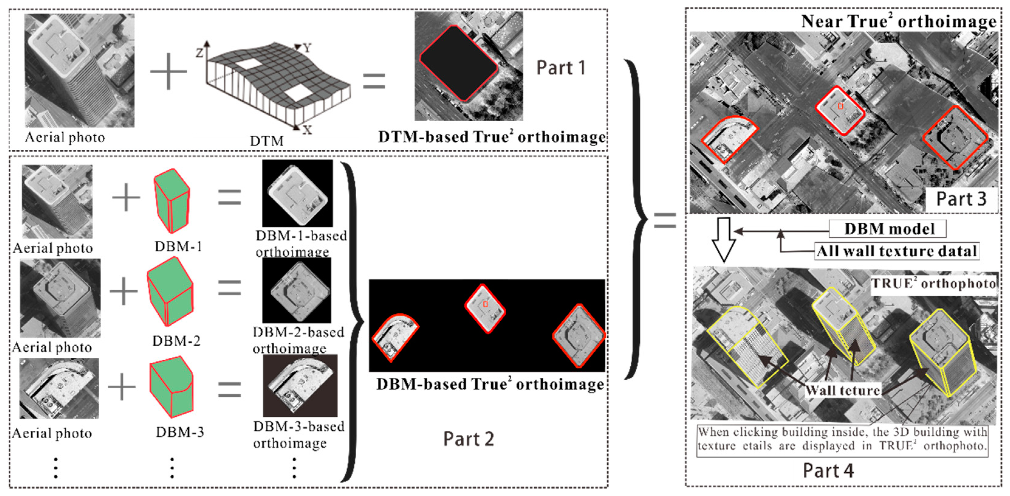
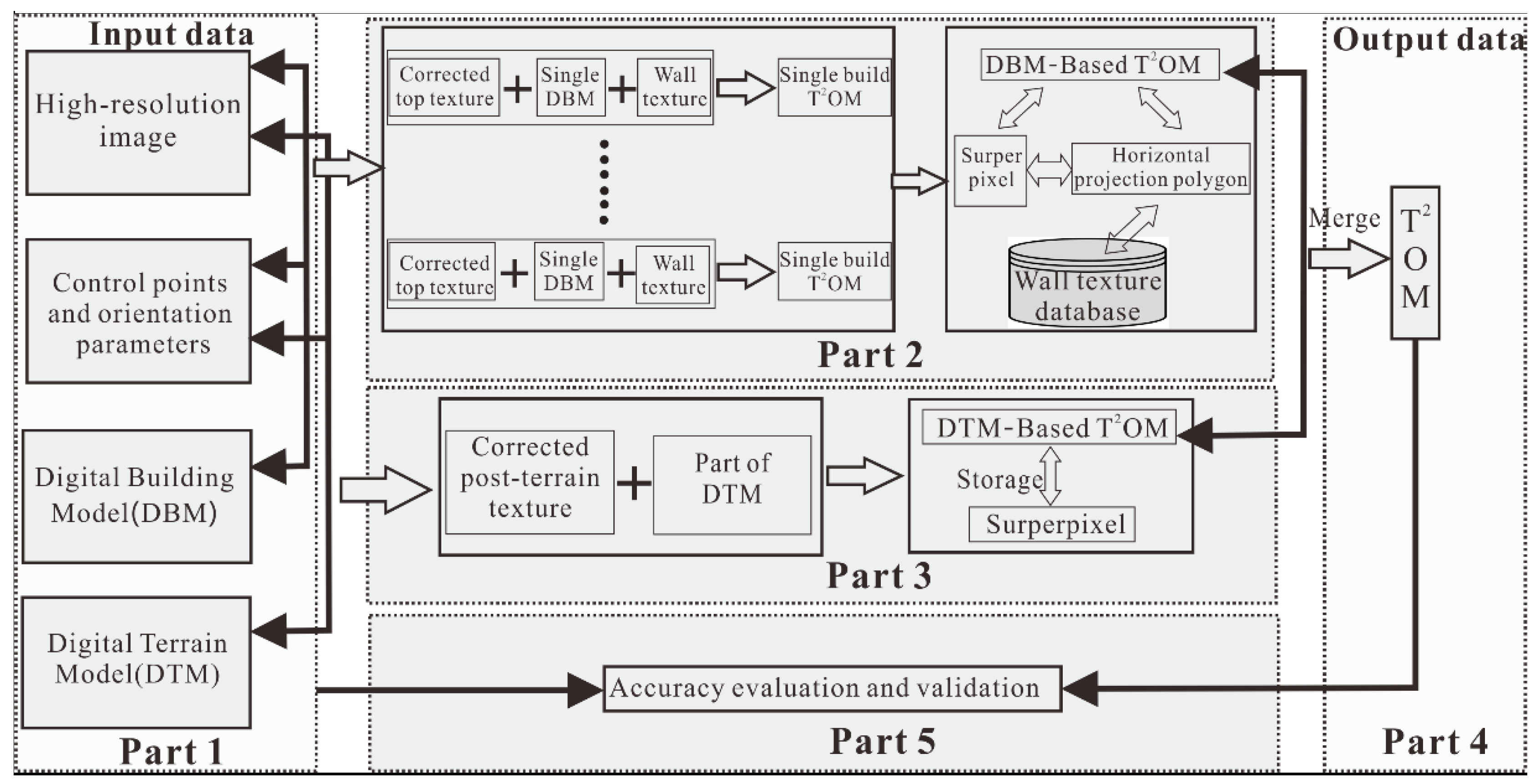
- DBM-based single-building T2OM generation, which consists of orthorectifying both the building roof and building facades: a concept, named “superpixel” is proposed the for storage of building texture, building ID, etc. information.
- (2)
- DBM-based multiple-building T2OM generation: merging the DBM-based single-building T2OM, including organization of the building ID, building façade, building corner coordinates, etc.
- (3)
- DTM-based T2OM generation for the orthorectification of gentle and continuously elevated hilly areas.
- (4)
- DTM- and DBM-based T2OM merging, which is for merging DTM- and DBM-based T2OM for the creation of an entire T2OM.
3.1. Generation of a DBM-Based Single-Building T2OM
- (1)
- Determining the size of the T2OM: The resulting DBM-based single-building T2OM is expressed as a raster image with pixels arranged in rows and columns. Since the resulting orthoimage is orthorectified from raster image input (called original image) using the DBM data, the size of the output image is defined [9] as
- (2)
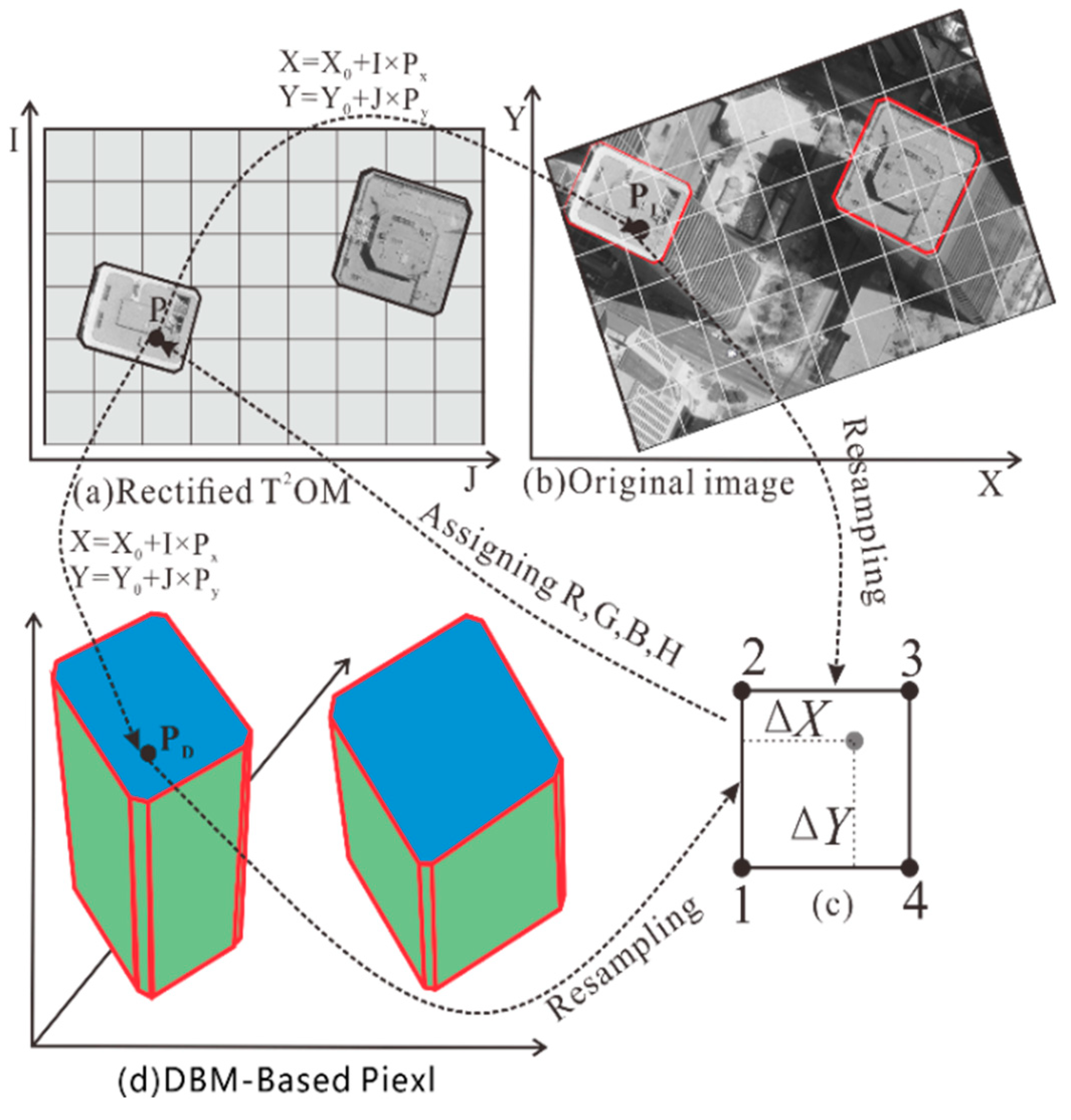
- Computing the X, Y coordinate of each pixel: In Figure 2, P (I, J) is a given point pixel on the roof of the T2OM building roof, and their raster rows and columns can be transformed to the coordinates of the output T2OM, i.e.,
- (3)
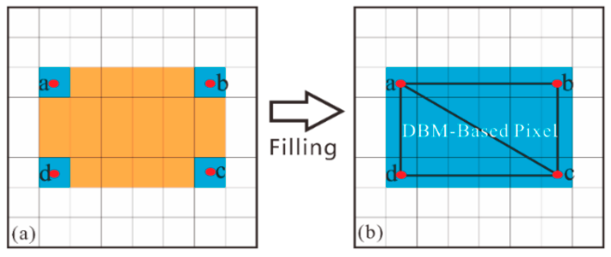
- Computing the Z coordinate of P (I, J): In order to perform orthorectification, we also need to know the Z coordinates of the pixel P (I, J) in the output roof T2OM and this is obtained from DBM. However, DBM data only have vector coordinates at corner points. Therefore, it is necessary to interpolate an elevation to the roof pixel of the building. As shown in Figure 3, the elevation (height) is obtained only for pixels with corner points (blue pixels in Figure 3), while the other pixels (orange in Figure 3) are calculated by:
- (4)
- Computing the corresponding coordinate in the original image: In order to orthorectify the source image, the corresponding coordinate of the source image pixel in the output image is calculated by:
- (5)
- Assigning the gray value to pixels: Since the grid of pixels in the source image rarely matches the grid of the output orthoimage, a re-sampling of the pixels has to be performed in order to assign gray value to the pixels in the output image. The nearest neighbor is employed because it directly transfers the original data values without averaging them. The computational procedure is illustrated in Figure 2.
- (6)
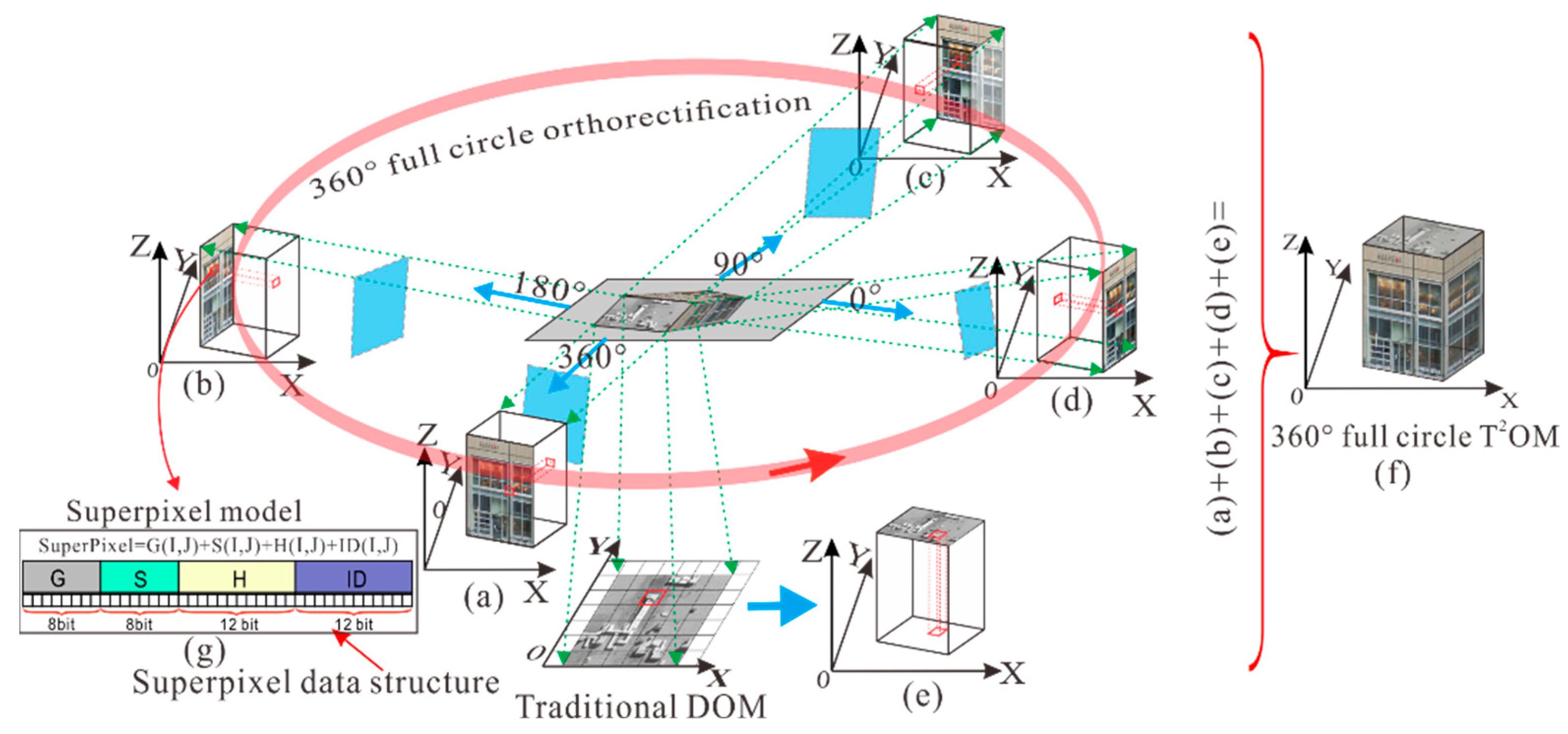
- Storing the data for DBM-based building roof T2OM: As can be seen from the above, T2OM needs to store more information than the traditional TOM does, such as building roof texture, facade texture, and façade Z coordinates. For this reason, “superpixel” is presented and has the following characteristics (see Figure 4): (1) it inherits the original image gray information; (2) the gray value, elevation, building ID, and facade texture index ID are stored; (3) each pixel coordinate is directly interconnected with the building ID and façade texture ID.
- (1)
- G (I, J) stands for storage of the gray at i-th row and j-th column in the image coordinate system whose value is 0–255.
- (2)
- S (I, J) stands for storage of the building corner coordinate subdivision grid identification value, which occupies 8 bits. That is, by dividing a single pixel into 256 subdivision sequences, the accuracy of vector to grid data conversion is improved. For a given point P (XP, YP), this can be expressed as (ip, jp) after the conversion of the vector to the grid. The lost information is . With this information, Sx can be calculated through Equation (8).
- (3)
- H (I, J) stands for the storage of the building height or DTM height with a floating format.
- (4)
- ID stands for the storage of building ID. An ID can be used to call for the facade texture. A large city may have hundreds of buildings; therefore, 12 bits are designed to store 0 to 4095 buildings.
3.2. Generation for DBM-Based Multiple-Building T2OMs
3.3. Generation of DTM-Based T2OM
3.4. Merging DTM- and DBM-Based T2OMs
4. Experiments and Analysis
4.1. Metadata of T2OM
4.2. T2OM Generation
4.2.1. Experimental Result with Dataset 1
- (1)
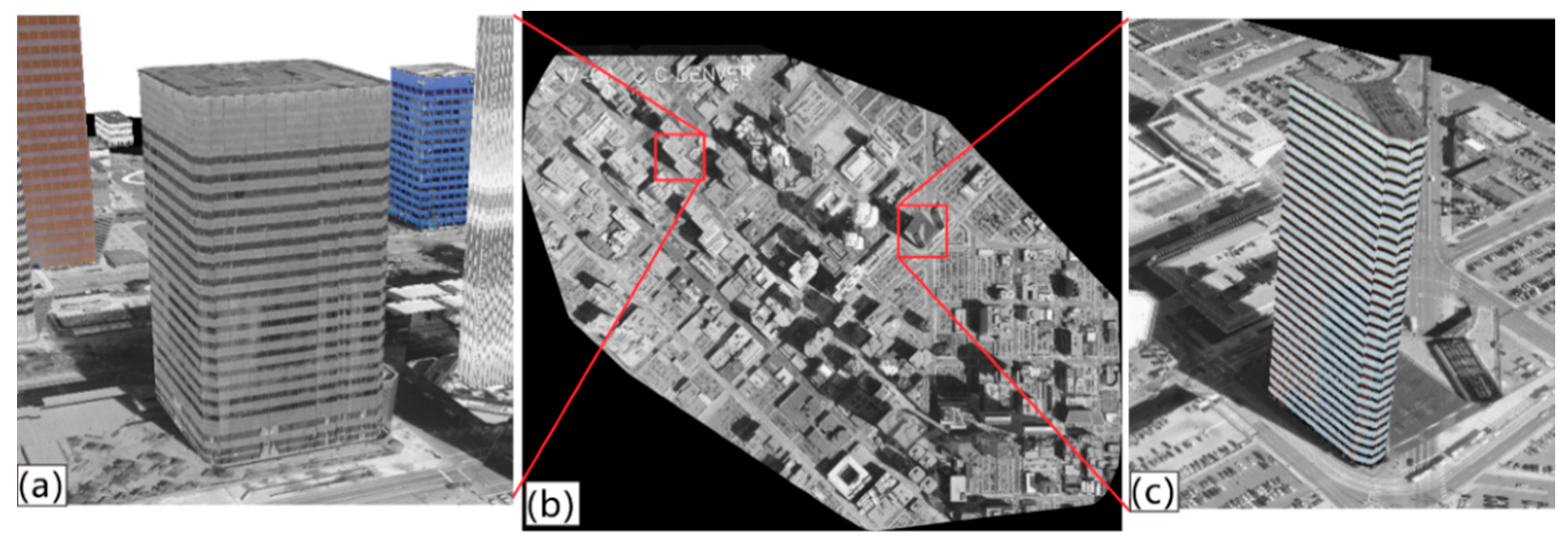
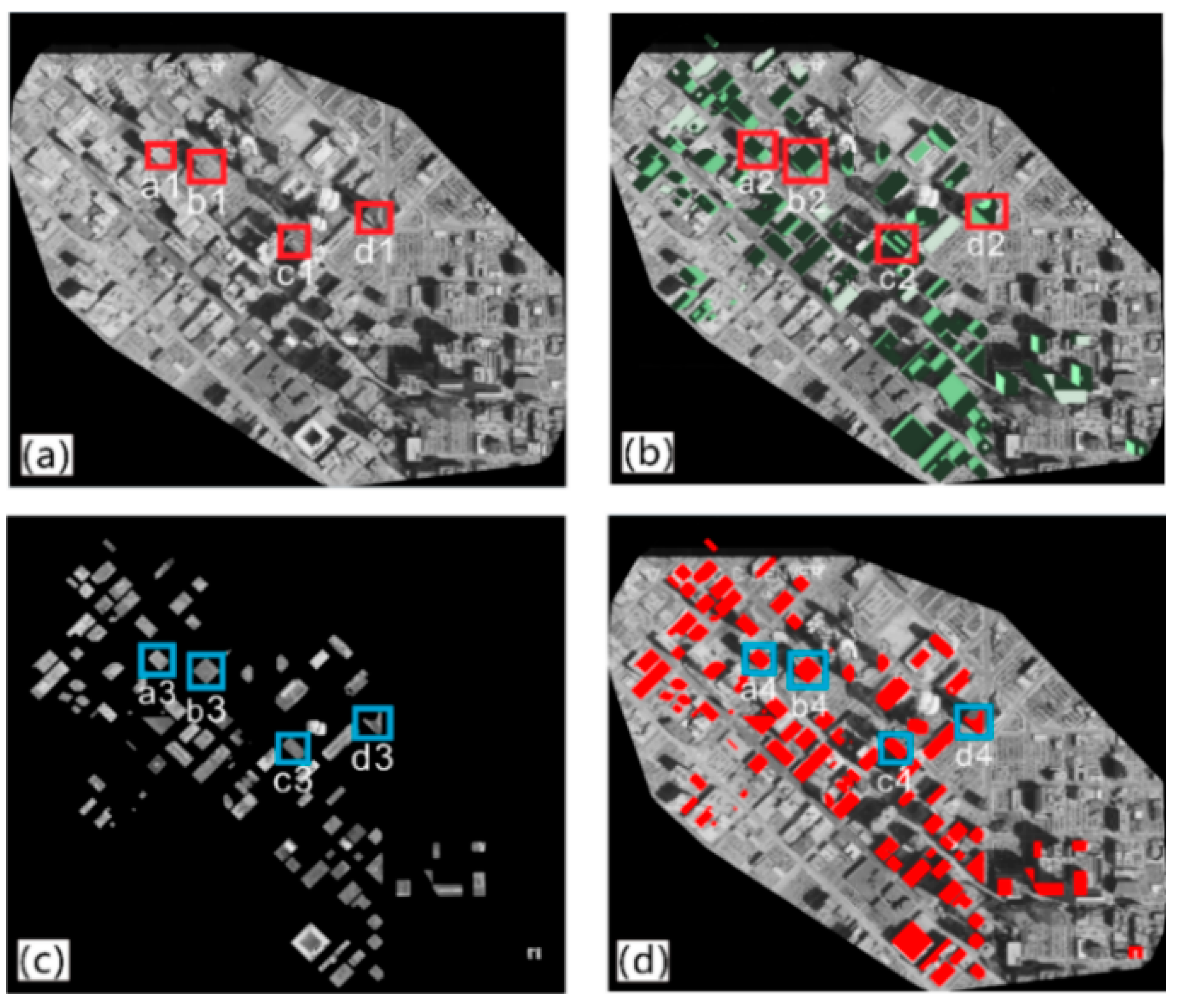
- DTM data: Figure 11a shows DTM data from Denver, CO, USA, which is represented as a height–depth map, where the darker the color is, the lower the height, and vice versa, because the topography of the city is relatively flat. Thus, the elevations shown on the ground are relatively similar (the colors shown are similar). The accuracy of plane surface coordinates and vertical coordinates are about 0.1 m and 0.2 m, respectively. The horizontal datum is GRS 1980, and the vertical datum is NAD83.
- (2)
- Aerial Image data: Figure 11b shows the original aerial image acquired using the RC30 aerial camera lens in Denver. The flight altitude in Denver is 1650 m higher than the mean ground elevation of the imaged area. Aerial photographs were initially recorded on film and then scanned into digital format at a pixel resolution of 25 μm.
- (3)
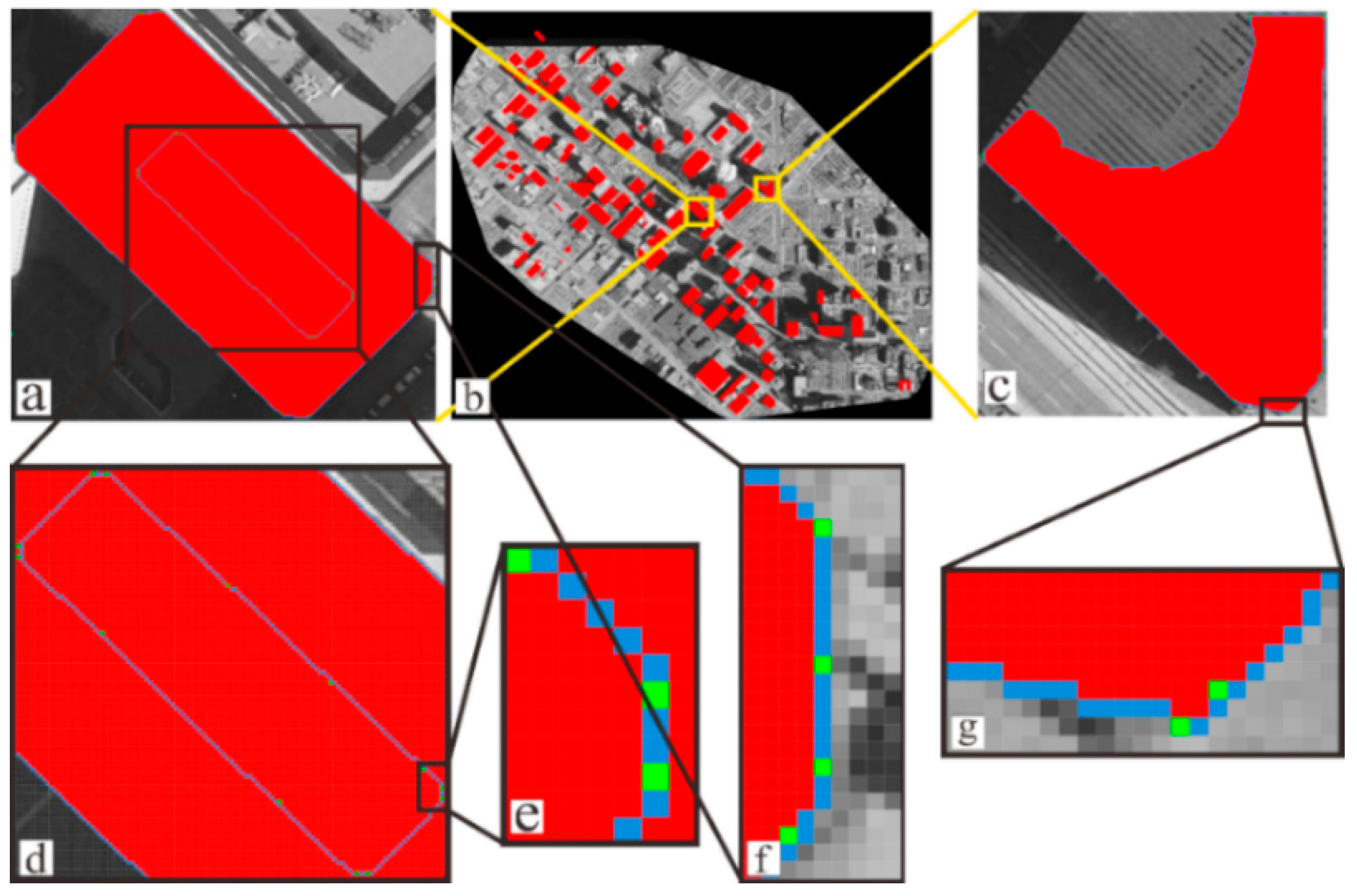
- DBM data: Figure 11c shows Denver DBM data, and these buildings with a ground resolution of about 25.4 cm per pixel were identified. Each building model contains building corner point information and elevation texture information.
- (1)
- DBM-based building roof orthorectification
- (2)
- DBM-based building façade orthorectification
4.2.2. Experimental Result with Dataset 2
- (1)
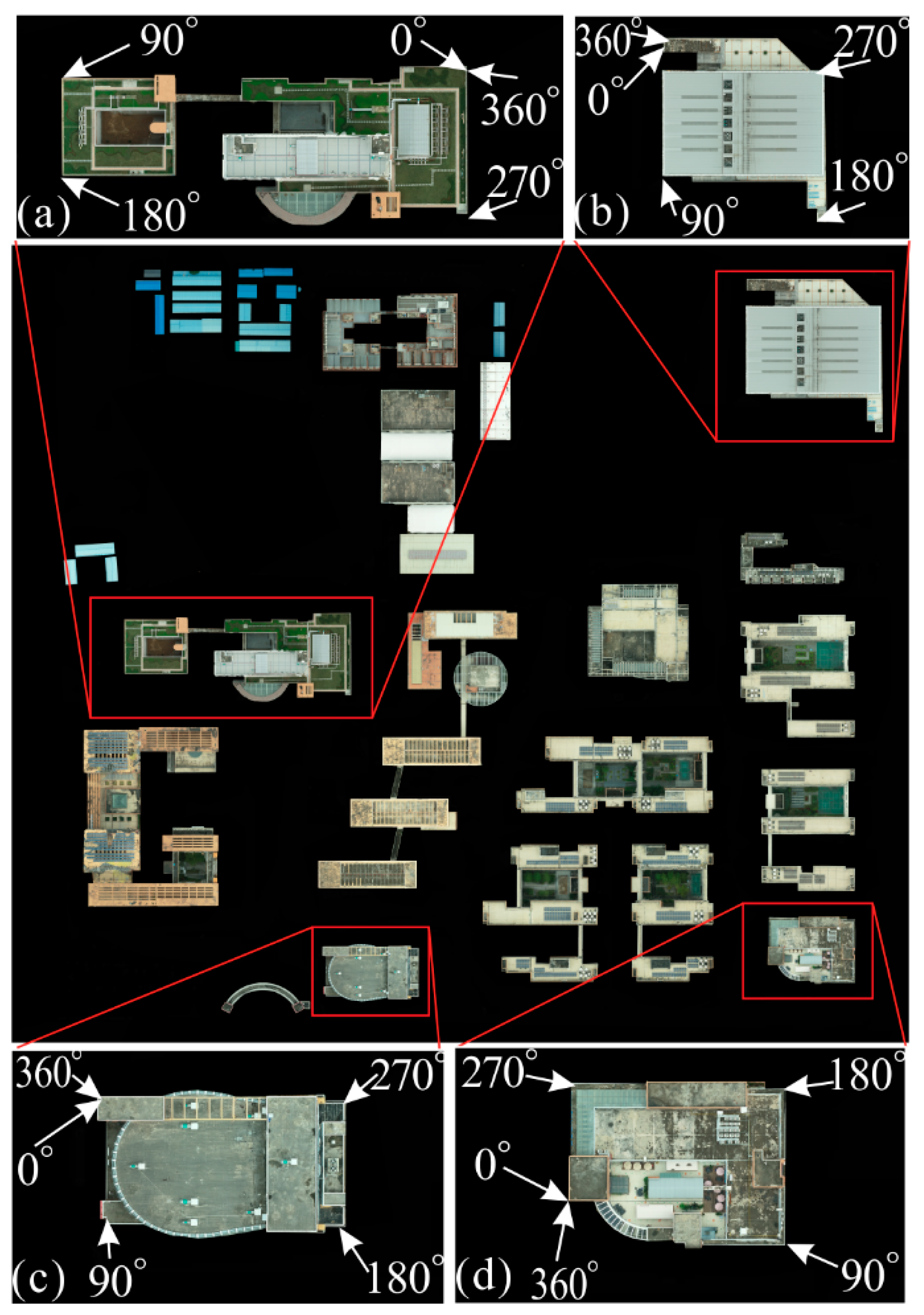
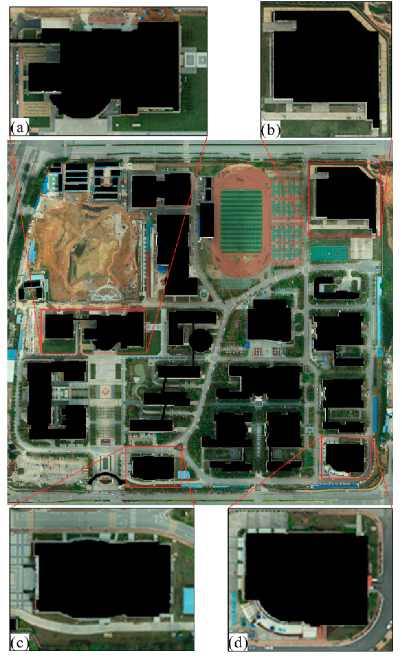
- DTM data: Figure 16a shows DTM data from Nanning, China, represented as a height–depth map, where the darker the color is, the lower the height, and vice versa, because the topography of the city is relatively flat. Thus, the elevations shown on the ground are relatively similar (the colors shown are similar). The accuracy of the plane surface coordinates and vertical coordinates are about 0.1 m and 0.2 m, respectively. The horizontal datum is GRS 1980, and the vertical datum is NAD83.
- (2)
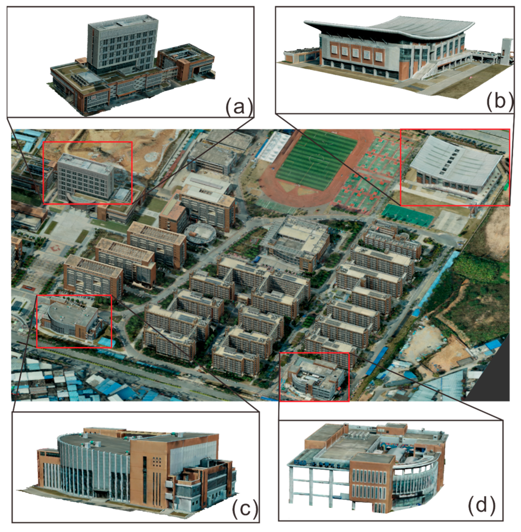
- Aerial Image data: Figure 16b shows the original aerial image acquired using the CMOS lens in Nanning. The flight altitude in Nanning is 200 m higher than the average ground elevation of the imaging area.
- (3)
- DBM data: Figure 16c shows Nanning DBM data, and buildings with a ground resolution of about 25.4 cm per pixel were identified. Each building model contains building corner point information and elevation texture information.
- (1)
- DBM-based building roof orthorectification
- (2)
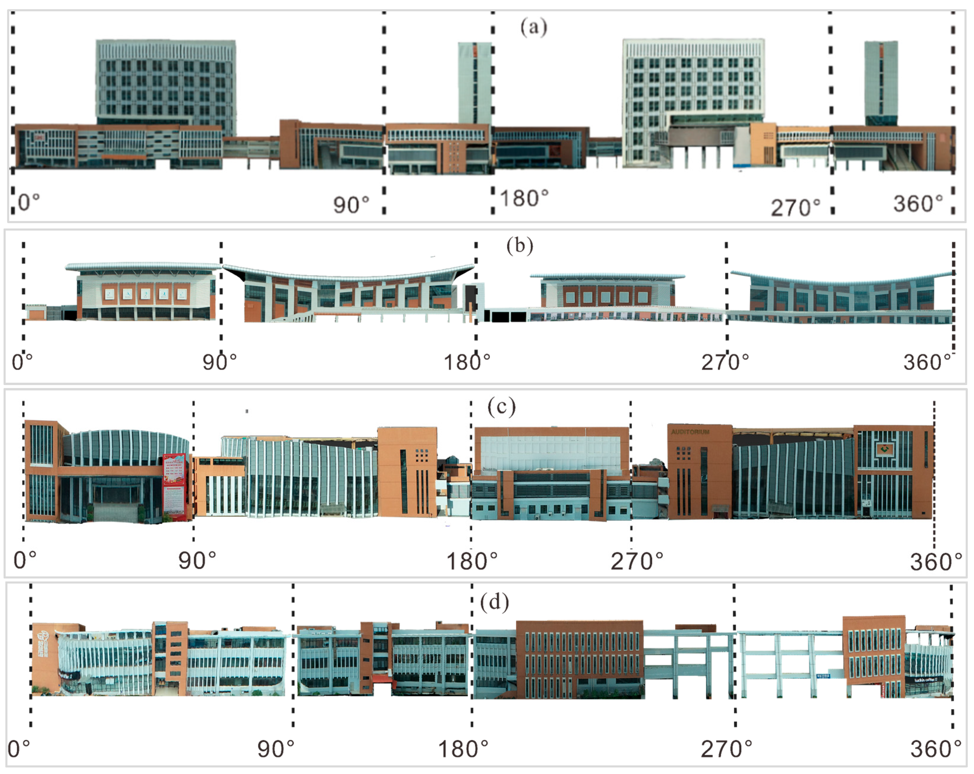
- DBM-based building façade orthorectification
4.2.3. T2OM 3D Measurement
4.3. Accuracy Evaluation and Analysis
4.4. Discussion
5. Conclusions
Author Contributions
Funding
Data Availability Statement
Acknowledgments
Conflicts of Interest
References
- Federal Geographic Data Committee. Fact Sheet: National Digital Geospatial Data Framework: A Status Report; Federal Geographic Data Committee: Reston, VA, USA, July 1997; 37p.
- Liu, Y.; Zheng, X.; Ai, G.; Zhang, Y.; Zuo, Y. Generating a High-Precision True Digital Orthophoto Map Based on UAV Images. ISPRS Int. J. Geo-Inf. 2018, 7, 333. [Google Scholar] [CrossRef]
- Maitra, J.B. The National Spatial Data Infrastructure in the United States: Standards; Metadata, Clearinghouse, and Data Access; Federal Geographic Data Committee c/o US Geological Survey: Reston, VA, USA, 1998. [Google Scholar]
- Yang, M.; Liu, J.; Zhang, Y.; Li, X. Design and Construction of Massive Digital Orthophoto Map Database in China. ISPRS Int. Arch. Photogramm. Remote Sens. Spat. Inf. Sci. 2016, 41, 103–106. [Google Scholar] [CrossRef]
- Zhou, G. Onboard Processing for Satellite Remote Sensing Images; CRC Press: Boca Raton, FL, USA, 2022; ISBN 978-10-32-329642. [Google Scholar]
- Federal Geographic Data Committee. Development of a National Digital Geospatial Data Framework; Federal Geographic Data Committee: Reston, VA, USA, 1995. [CrossRef]
- Jamil, A.; Bayram, B. Tree Species Extraction and Land Use/Cover Classification From High-Resolution Digital Orthophoto Maps. IEEE J. Sel. Top. Appl. Earth Obs. Remote Sens. 2017, 11, 89–94. [Google Scholar] [CrossRef]
- Zhou, G.; Schickler, W.; Thorpe, A.; Song, P.; Chen, W.; Song, C. True orthoimage generation in urban areas with very tall buildings. Int. J. Remote Sens. 2004, 25, 5163–5180. [Google Scholar] [CrossRef]
- Zhou, G.; Chen, W.; Kelmelis, J.A.; Zhang, D. A comprehensive study on urban true orthorectification. IEEE Trans. Geosci. Remote Sens. 2005, 43, 2138–2147. [Google Scholar] [CrossRef]
- Amhar, F.; Jansa, J.; Ries, C. The generation of true orthophotos using a 3D building model in conjunction with a conventional DTM. Int. Arch. Photogramm. Remote Sens. 1998, 32, 16–22. [Google Scholar]
- Schickier, W.; Thorpe, A. Operational procedure for automatic true orthophoto generation. Int. Arch. Photo-Grammetry Remote Sens. 1998, 32, 527–532. [Google Scholar]
- Di, K.; Jia, M.; Xin, X.; Wang, J.; Liu, B.; Li, J.; Xie, J.; Liu, Z.; Peng, M.; Yue, Z.; et al. High-Resolution Large-Area Digital Orthophoto Map Generation Using LROC NAC Images. Photogramm. Eng. Remote Sens. 2019, 85, 481–491. [Google Scholar] [CrossRef]
- Skarlatos, D. Orthophotograph Production in Urban Areas. Photogramm. Rec. 1999, 16, 643–650. [Google Scholar] [CrossRef]
- Zhou, G.; Li, H.; Song, R.; Wang, Q.; Xu, J.; Song, B. Orthorectification of Fisheye Image under Equidistant Projection Model. Remote Sens. 2022, 14, 4175. [Google Scholar] [CrossRef]
- Greenfeld, J. Evaluating the accuracy of digital orthophoto quadrangles (DOQ) in the context of parcel-based GIS. Photogramm. Eng. Remote Sens. 2001, 67, 199–206. [Google Scholar]
- Haggag, M.; Zahran, M.; Salah, M. Towards automated generation of true orthoimages for urban areas. Am. J. Geogr. Inf. Syst. 2018, 7, 67–74. [Google Scholar] [CrossRef]
- Mayr, W. True orthoimages. GIM Int. 2002, 37, 37–39. [Google Scholar]
- Rau, J.-Y.; Chen, N.-Y.; Chen, L.-C. True orthophoto generation of built-up areas using multi-view images. Photogramm. Eng. Remote Sens. 2002, 68, 581–588. [Google Scholar]
- Shoab, M.; Singh, V.K.; Ravibabu, M.V. High-Precise True Digital Orthoimage Generation and Accuracy Assessment based on UAV Images. J. Indian Soc. Remote Sens. 2021, 50, 613–622. [Google Scholar] [CrossRef]
- Jauregui, M.; Vílchez, J.; Chacón, L. A procedure for map updating using digital mono-plotting. Comput. Geosci. 2002, 28, 513–523. [Google Scholar] [CrossRef]
- Siachalou, S. Urban orthoimage analysis generated from IKONOS data. Int. Arch. Photogramm. Remote Sens. Spat. Inf. Sci. 2004, 35, 12–23. [Google Scholar]
- Biasion, A.; Dequal, S.; Lingua, A. A new procedure for the automatic production of true orthophotos. Int. Arch. Photogramm. Remote Sens. Spat. Inf. Sci. 2004, 35, 1682–1777. [Google Scholar]
- Shin, Y.H.; Lee, D.-C. True Orthoimage Generation Using Airborne LiDAR Data with Generative Adversarial Network-Based Deep Learning Model. J. Sensors 2021, 2021, 4304548. [Google Scholar] [CrossRef]
- Yao, J.; Zhang, Z.M. Hierarchical shadow detection for color aerial images. Comput. Vis. Image Underst. 2006, 102, 60–69. [Google Scholar] [CrossRef]
- Xie, W.; Zhou, G. Experimental realization of urban large-scale true orthoimage generation. In Proceedings of the ISPRS Congress, Beijing, China, 3–11 July 2008; pp. 3–11. [Google Scholar]
- Zhou, G.; Jezek, K.C. Satellite photograph mosaics of Greenland from the 1960s era. Int. J. Remote Sens. 2002, 23, 1143–1159. [Google Scholar] [CrossRef]
- Zhou, G.; Schickler, W. True orthoimage generation in extremely tall building urban areas. Int. J. Remote Sens. 2004, 25, 5161–5178. [Google Scholar] [CrossRef]
- Zhou, G. Near Real-Time Orthorectification and Mosaic of Small UAV Video Flow for Time-Critical Event Response. IEEE Trans. Geosci. Remote Sens. 2009, 47, 739–747. [Google Scholar] [CrossRef]
- Zhou, G.; Wang, Y.; Yue, T.; Ye, S.; Wang, W. Building occlusion detection from ghost images. IEEE Trans. Geosci. Remote Sens. 2016, 55, 1074–1084. [Google Scholar] [CrossRef]
- Zhang, R.; Liu, N.; Huang, J.; Zhou, X. On-Board Ortho-Rectification for Images Based on an FPGA. Remote Sens. 2017, 9, 874. [Google Scholar] [CrossRef]
- Zhou, G.; Zhang, R.; Zhang, D.; Huang, J.; Baysal, O. Real-time ortho-rectification for remote-sensing images. Int. J. Remote Sens. 2018, 40, 2451–2465. [Google Scholar] [CrossRef]
- Zhou, G.; Bao, X.; Ye, S.; Wang, H.; Yan, H. Selection of Optimal Building Facade Texture Images From UAV-Based Multiple Oblique Image Flows. IEEE Trans. Geosci. Remote Sens. 2020, 59, 1534–1552. [Google Scholar] [CrossRef]
- Jensen, L.B.; Per, S.; Nielsen; Alexander, T.; Mikkelsen, P.S. The Potential of the Technical University of Denmark in the Light of Sustainable Livable Cities. Des. Civ. Environ. Eng. 2014, 90. [Google Scholar] [CrossRef]
- Huang, X.; Zhang, L. Morphological Building/Shadow Index for Building Extraction From High-Resolution Imagery over Urban Areas. IEEE J. Sel. Top. Appl. Earth Obs. Remote Sens. 2011, 5, 161–172. [Google Scholar] [CrossRef]
- Yu, B.; Wang, L.; Niu, Z. A novel algorithm in buildings/shadow detection based on Harris detector. Optik 2014, 125, 741–744. [Google Scholar] [CrossRef]
- Gharibi, H.; Habib, A. True Orthophoto Generation from Aerial Frame Images and LiDAR Data: An Update. Remote Sens. 2018, 10, 581. [Google Scholar] [CrossRef]
- Zhou, G. Urban High-Resolution Remote Sensing: Algorithms and Modeling; CRC Press: Boca Raton, FL, USA, 2020. [Google Scholar] [CrossRef]
- Liu, X.; Zhou, G.; Zhang, W.; Luo, S. Study on Local to Global Radiometric Balance for Remotely Sensed Imagery. Remote Sens. 2021, 13, 2068. [Google Scholar] [CrossRef]
- Wang, Q.; Zhou, G.; Song, R.; Xie, Y.; Luo, M.; Yue, T. Continuous space ant colony algorithm for automatic selection of or-thophoto mosaic seamline network. ISPRS J. Photogramm. Remote Sens. 2022, 186, 201–217. [Google Scholar] [CrossRef]
- Vassilopoulou, S.; Hurni, L.; Dietrich, V.; Baltsavias, E.; Pateraki, M.; Lagios, E.; Parcharidis, I. Orthophoto generation using IKONOS imagery and high-resolution DEM: A case study on volcanic hazard monitoring of Nisyros Island (Greece). ISPRS J. Photogramm. Remote Sens. 2002, 57, 24–38. [Google Scholar] [CrossRef]
- Cameron, A.; Miller, D.; Ramsay, F.; Nikolaou, I.; Clarke, G. Temporal measurement of the loss of native pinewood in Scotland through the analysis of orthorectified aerial photographs. J. Environ. Manag. 2000, 58, 33–43. [Google Scholar] [CrossRef]
- Passini, R.; Jacobsen, K. Accuracy analysis of digital orthophotos from very high resolution imagery. International Archives of the Photogrammetry. Remote Sens. Spat. Inf. Sci. ISPRS Arch. 2004, 35 Pt B4, 695–700. [Google Scholar] [CrossRef]
- Piatti, E.J.; Lerma, J.L. Generation of True Ortho-Images Based On Virtual Worlds: Learning Aspects. Photogramm. Rec. 2014, 29, 49–67. [Google Scholar] [CrossRef]
- Yoo, E.J.; Lee, D.-C. True orthoimage generation by mutual recovery of occlusion areas. GIScience Remote Sens. 2015, 53, 227–246. [Google Scholar] [CrossRef]
- De Oliveira, H.C.; Dal Poz, A.P.; Galo, M.; Habib, A.F. Surface gradient approach for occlusion detection based on triangu-lated irregular network for true orthophoto generation. IEEE J. Sel. Top. Appl. Earth Obs. Remote Sens. 2018, 11, 443–457. [Google Scholar] [CrossRef]
- Zhou, G.; Sha, H. Building Shadow Detection on Ghost Images. Remote Sens. 2020, 12, 679. [Google Scholar] [CrossRef]
- Marsetič, A. Robust Automatic Generation of True Orthoimages rom Very High-Resolution Panchromatic Satellite Imagery Based on Image Incidence Angle for Occlusion Detection. IEEE J. Sel. Top. Appl. Earth Obs. Remote Sens. 2021, 14, 3733–3749. [Google Scholar] [CrossRef]
- Sheng, Y.; Gong, P.; Biging, G.S. True Orthoimage Production for Forested Areas from Large-Scale Aerial Photographs. Photogramm. Eng. Remote Sens. 2003, 69, 259–266. [Google Scholar] [CrossRef]
- Leone, A.; Distante, C. Shadow detection for moving objects based on texture analysis. Pattern Recognit. 2007, 40, 1222–1233. [Google Scholar] [CrossRef]
- Makarau, A.; Richter, R.; Muller, R.; Reinartz, P. Adaptive Shadow Detection Using a Blackbody Radiator Model. IEEE Trans. Geosci. Remote Sens. 2011, 49, 2049–2059. [Google Scholar] [CrossRef]
- Tiwari, S.; Chauhan, K.; Kurmi, Y. Shadow Detection and Compensation in Aerial Images using MATLAB. Int. J. Comput. Appl. 2015, 119, 5–9. [Google Scholar] [CrossRef]
- Li, D.; Wang, M.; Pan, J. Auto-dodging processing and its application for optical RS images. Geomat. Inf. Sci. Wuhan Univ. 2006, 31, 753–756. [Google Scholar]
- Pan, J.; Wang, M. A Multi-scale Radiometric Re-processing Approach for Color Composite DMC Images. Geomat. Infor. Sci. Wuhan Univ. 2007, 32, 800–803. [Google Scholar]
- Zhou, G.; Pan, Q.; Yue, T.; Wang, Q.; Sha, H.; Huang, S.; Liu, X. Vector and Raster Data Storage based on Morton Code. ISPRS Int. Arch. Photogramm. Remote Sens. Spat. Inf. Sci. 2018, XLII-3, 2523–2526. [Google Scholar] [CrossRef]
- Chan, C.; Tan, S. Determination of the minimum bounding box of an arbitrary solid: An iterative approach. Comput. Struct. 2001, 79, 1433–1449. [Google Scholar] [CrossRef]
- Fan, H.; Wang, Y.; Gong, J. Layout graph model for semantic façade reconstruction using laser point clouds. Geo Spatial Inf. Sci. 2021, 24, 403–421. [Google Scholar] [CrossRef]









| DBM-Based Pixel | Row | Column | Gray Value | Sub Ordinal | Height | BuildingID |
|---|---|---|---|---|---|---|
| BP1 | I(BP1) | J(BP1) | G1 | id(BP1) (r,c) | h(BP1) | B1 |
| BP2 | I(BP2) | J(BP2) | G2 | 0 | h(BP2) | B1 |
| … | … | … | … | … | … | … |
| BPi | I(BPi) | J(BPi) | Gi | id(BPi) (r,c) | h(BPi) | B1 |
| BPi + 1 | I(BPi + 1) | J(BPi + 1) | Gi + 1 | 0 | h(BPi+1) | B1 |
| … | … | … | … | … | … | …. |
| Pixel | Gray (8 bit) | Hight (H, 12 bit) | TextureID (TID, 12 bit) | Notes | ||
|---|---|---|---|---|---|---|
| 1 | 11000110 | 000100000010 | 000001000001 | Gray = 198 |  | Wall 1 H = 25.8 TID = 65 |
| 2 | 11010011 | 000100000010 | 000001000001 | Gray = 211 | ||
| 3 | 11010000 | 000100000010 | 000001000001 | Gray = 208 | ||
| … | … | … | … | … | ||
| 8 | 11010011 | 000100000010 | 000001000001 | Gray = 211 | ||
| 9 | 11001000 | 000100000010 | 000001000010 | Gray = 200 |  | Wall 2 H = 25.8 TID = 66 |
| 10 | 11101000 | 000100000010 | 000001000010 | Gray = 232 | ||
| … | … | … | … | … | ||
| 18 | 11011101 | 000100000010 | 000001000010 | Gray = 221 | ||
| 19 | 11011101 | 000100000010 | 000001000011 | Gray = 221 |  | Wall 3 H = 25.8 TID = 67 |
| 20 | 11011000 | 000100000010 | 000001000011 | Gray = 216 | ||
| … | … | … | … | … | ||
| 27 | 11011000 | 000100000010 | 000001000011 | Gray = 216 | ||
| 28 | 11010001 | 000100000010 | 000001000100 | Gray = 209 |  | Wall 4 H = 25.8 TID = 68 |
| 29 | 11011010 | 000100000010 | 000001000100 | Gray = 218 | ||
| … | … | … | … | … | ||
| 37 | 11011010 | 000100000010 | 000001000100 | Gray = 218 | ||
| Pixel | Gray (8 bit) | Hight (H, 12 bit) | TextureID (TID, 12 bit) | Notes | ||
|---|---|---|---|---|---|---|
| 1 | 11010101 | 000111010000 | 001100101001 | Gray = 213 |  | Wall 1 H = 46.4 TID = 809 |
| 2 | 11111101 | 000111010000 | 001100101001 | Gray = 253 | ||
| 3 | 11110001 | 000111010000 | 001100101001 | Gray = 241 | ||
| … | … | … | … | … | ||
| 9 | 11010100 | 000111010000 | 001100101001 | Gray = 212 | ||
| 10 | 11010111 | 000111010000 | 001100101010 | Gray = 215 |  | Wall 2 H = 46.4 TID = 810 |
| 11 | 11010101 | 000111010000 | 001100101010 | Gray = 213 | ||
| … | … | … | … | … | ||
| 22 | 11010101 | 000111010000 | 001100101010 | Gray = 213 | ||
| 23 | 11011111 | 000111010000 | 001100101011 | Gray = 223 |  | Wall 3 H = 46.4 TID = 811 |
| 24 | 11010111 | 000111010000 | 001100101011 | Gray = 215 | ||
| … | … | … | … | … | ||
| 30 | 11010111 | 000111010000 | 001100101011 | Gray = 215 | ||
| 31 | 11010101 | 000111010000 | 001100101100 | Gray = 213 |  | Wall 4 H = 46.4 TID = 812 |
| 32 | 11010111 | 000111010000 | 001100101100 | Gray = 215 | ||
| … | … | … | … | … | ||
| 47 | 11010101 | 000111010000 | 001100101100 | Gray = 213 | ||
| WallID | Wall Pixel Index | Texture Index | Hight |
|---|---|---|---|
| a1b1 | 1, 2, 3, 4, 5, 6, 7, 8 | 65 | 25.8 |
| b1c1 | 9, 10, 11, 12, 13, 14, 15, 16, 17, 18 | 66 | 25.8 |
| c1d1 | 19, 20, 21, 22, 23, 24, 25, 26, 27 | 67 | 25.8 |
| d1a1 | 28, 29, 30, 31, 32, 33, 34, 35, 36, 37 | 68 | 25.8 |
| WallID | Wall Pixel Index | Texture Index | Hight |
|---|---|---|---|
| a2b2 | 1, 2, 3, 4, 5, 6, 7, 8, 9 | 809 | 46.4 |
| b2c2 | 10, 11, 12, 13, 14, 15, 16, 17, 18, 19, 20, 21, 22 | 810 | 46.4 |
| c2d2 | 23, 24, 25, 26, 27, 28, 29, 30 | 811 | 46.4 |
| d2a2 | 31, 32, 33, 34, 35, 36, 37, 38, 39, 40, 41, 42, 43, 44, 45, 46, 47 | 812 | 46.4 |
| BuildingID | Type | RoofID | WallID | Properties | Others |
|---|---|---|---|---|---|
| B1 | Volume | R11 | W11, W12, W13… | Brick structure | … |
| B2 | Volume | R12 | W21, W22, W23… | reinforced concrete structure | … |
| B3 | Volume | R13 | W31, W32, W33… | steel structure | … |
| … | … | … | … | … | … |
| RoofID | Type | TextureID | PointID | Others |
|---|---|---|---|---|
| R11 | Polygon | TR11 | PR11, PR12, PR13… | … |
| R12 | Polygon | TR12 | PR21, PR22, PR23… | … |
| R13 | Polygon | TR13 | PR31, PR32, PR33… | … |
| … | … | … | … | … |
| WallID | Type | TextureID | PointID | Others |
|---|---|---|---|---|
| W11 | Polygon | TW11 | Pw11, Pw12, Pw13… | … |
| W12 | Polygon | TW12 | Pw21, Pw22, Pw23… | … |
| W13 | Polygon | TW13 | Pw31, Pw32, Pw33… | … |
| … | … | … | … | … |
| PointID | X, Y, Z Coord. | Pixel Coord. | Others | |||
|---|---|---|---|---|---|---|
| Pw11 | XW11 | YW11 | ZW11 | IW11 | JW11 | … |
| Pw12 | XW12 | YW12 | ZW12 | IW12 | JW12 | … |
| Pw13 | XW13 | YW13 | ZW13 | IW13 | JW13 | … |
| … | … | … | … | … | … | … |
| PR11 | XR11 | YR11 | ZR11 | IR11 | JR11 | … |
| PR12 | XR12 | YR12 | ZR12 | IR12 | JR12 | … |
| PR13 | XR13 | YR13 | ZR13 | IR13 | JR13 | … |
| … | … | … | … | … | … | … |
| TextureD | TextureName | FileAddress | Date | Fomat | Others |
|---|---|---|---|---|---|
| TW11 | WTN11 | WFA11 | WD11 | WF11 | … |
| TW12 | WTN12 | WFA12 | WD12 | WF12 | … |
| TW13 | WTN13 | WFA13 | WD13 | WF13 | … |
| … | … | … | … | … | … |
| TR11 | PTN11 | PFA11 | PD11 | PF11 | … |
| TR12 | PTN12 | PFA12 | PD12 | PF12 | … |
| TR13 | PTN13 | PFA13 | PD13 | PF13 | … |
| … | … | … | … | … | … |
| File Section | Properties | Description |
|---|---|---|
| File flag block | m_FileProperty | Identifier “fus” (char type) |
| m_Version | Version number (int type) | |
| Image header information | m_UpleftCoordinateX | Image coordinate lower right X value (double type, units: meters) |
| m_UpleftCoordinateY | Image coordinate lower right Y value (double type, units: meters) | |
| m_TMaxZ | The highest point in the DTM file (double type, in meters) | |
| m_TMinZ | The lowest point in the DTM file (double type, in meters) | |
| m_BMaxZ | Maximum building height in DBM (double type in meters) | |
| m_BMinZ | Minimum building height in DBM (double type in meters) | |
| m_IntervalX | Unit interval in X-axis direction (double type in meters) | |
| m_IntervalY | Unit interval in Y-axis direction (double type, units: meters) | |
| m_FileHigh | Image height (int type) | |
| m_FileWidth | Image width (int type) | |
| Z_Tresolution | Topographic data unit elevation level (double type, units: meters) | |
| Z_Bresolution | Building data unit elevation level (type double, in meters) | |
| Build_Num | Number of building objects elements (type int) | |
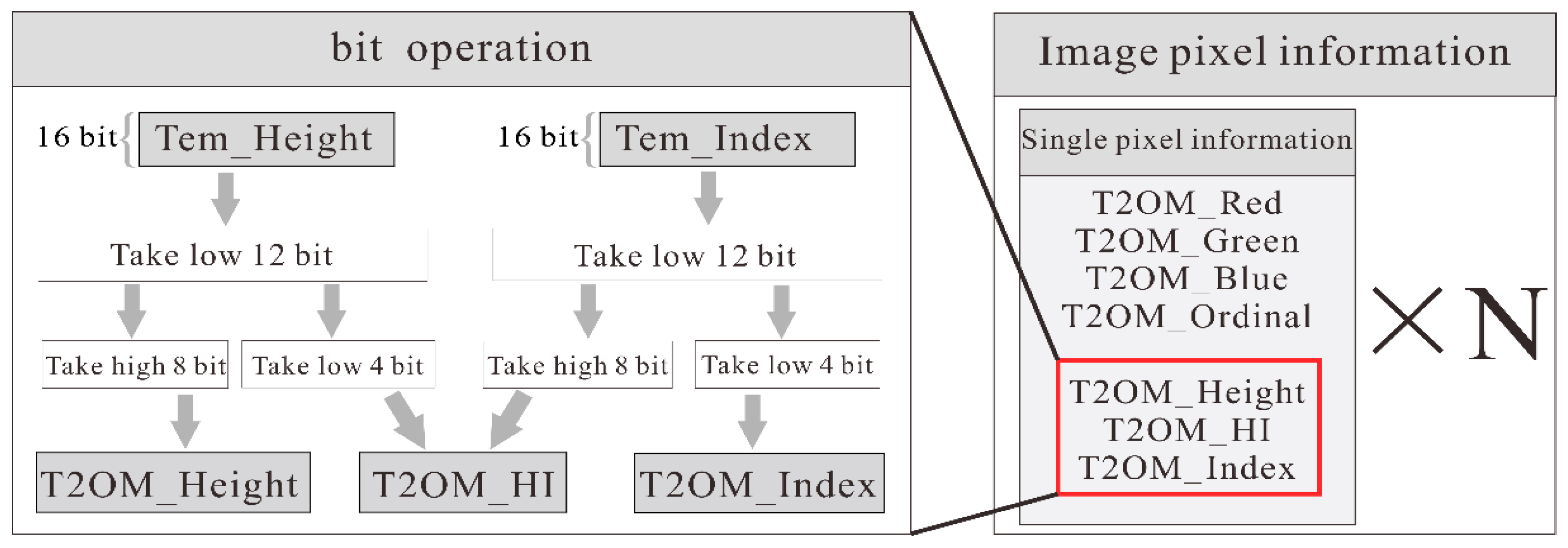
| Image Pixels Information | T2OM_Grey | Pixel grey component (unsigned char type) |
| T2OM_Ordinal | Subdivision grid order (unsigned char type) | |
| T2OM_Height | Elevation level high 8 bits (unsigned char type) | |
| T2OM_HI | Elevation level low 4 bits, logo high 4 bits (unsigned char type) | |
| T2OM_Index | Marker data low 8 bits (unsigned char type) |
| Building | Xori | Yori | Zori | id(r,c) | h | Xbc | Ybc | Zbc |
|---|---|---|---|---|---|---|---|---|
| a | 1286.850 | 1306.000 | 5551.700 | 14 | 1973 | 1286.840 | 1306.030 | 5551.600 |
| 1346.850 | 1245.000 | 5551.700 | 14 | 1973 | 1346.840 | 1245.030 | 5551.600 | |
| 1355.000 | 1237.975 | 5551.700 | 241 | 1973 | 1355.030 | 1237.970 | 5551.600 | |
| 1356.000 | 1237.850 | 5551.700 | 209 | 1973 | 1356.030 | 1237.840 | 5551.600 | |
| b | 1931.937 | 1424.000 | 5533.400 | 15 | 1876 | 1931.910 | 1424.030 | 5533.330 |
| 1932.150 | 1440.000 | 5533.400 | 3 | 1876 | 1932.160 | 1440.030 | 5533.330 | |
| 1910.850 | 1462.000 | 5533.400 | 14 | 1876 | 1910.840 | 1462.030 | 5533.330 | |
| 1906.000 | 1464.150 | 5533.400 | 33 | 1876 | 1906.030 | 1464.160 | 5533.330 | |
| c | 2990.850 | 1244.000 | 5462.500 | 14 | 1499 | 2990.840 | 1244.030 | 5462.330 |
| 2912.850 | 1151.000 | 5462.500 | 14 | 1499 | 2912.840 | 1151.030 | 5462.330 | |
| 2911.850 | 1148.000 | 5462.500 | 14 | 1499 | 2911.840 | 1148.030 | 5462.330 | |
| 2964.850 | 1093.000 | 5462.500 | 14 | 1499 | 2964.840 | 1093.030 | 5462.330 | |
| d | 3339.000 | 1882.850 | 5755.800 | 209 | 3057 | 3339.030 | 1882.840 | 5755.760 |
| 3341.096 | 1883.000 | 5755.800 | 2 | 3057 | 3341.090 | 1883.030 | 5755.760 | |
| 3344.850 | 1881.000 | 5755.800 | 14 | 3057 | 3344.840 | 1881.030 | 5755.760 | |
| 3356.054 | 1864.000 | 5755.800 | 1 | 3057 | 3356.030 | 1864.030 | 5755.760 |
Publisher’s Note: MDPI stays neutral with regard to jurisdictional claims in published maps and institutional affiliations. |
© 2022 by the authors. Licensee MDPI, Basel, Switzerland. This article is an open access article distributed under the terms and conditions of the Creative Commons Attribution (CC BY) license (https://creativecommons.org/licenses/by/4.0/).
Share and Cite
Zhou, G.; Wang, Q.; Huang, Y.; Tian, J.; Li, H.; Wang, Y. True2 Orthoimage Map Generation. Remote Sens. 2022, 14, 4396. https://doi.org/10.3390/rs14174396
Zhou G, Wang Q, Huang Y, Tian J, Li H, Wang Y. True2 Orthoimage Map Generation. Remote Sensing. 2022; 14(17):4396. https://doi.org/10.3390/rs14174396
Chicago/Turabian StyleZhou, Guoqing, Qingyang Wang, Yongsheng Huang, Jin Tian, Haoran Li, and Yuefeng Wang. 2022. "True2 Orthoimage Map Generation" Remote Sensing 14, no. 17: 4396. https://doi.org/10.3390/rs14174396
APA StyleZhou, G., Wang, Q., Huang, Y., Tian, J., Li, H., & Wang, Y. (2022). True2 Orthoimage Map Generation. Remote Sensing, 14(17), 4396. https://doi.org/10.3390/rs14174396


