


Performance Evaluation of Random Access Methods for IoT-over-Satellite


Abstract
:1. Introduction
- It presents an emulation framework that predicts the uplink LoRa performance for IoT-over-Satellite networks.
- It evaluates the uplink packet error rate (PER) and bit error rate (BER) of the practical Walker-Delta constellations and the Walker-Star constellations.
- It evaluates the uplink PER and BER of the IoT-over-Satellite system in four different access methods in a shared radio spectrum.
- It shows the impact of fading, Doppler shift, and practical interference to the IoT-over-Satellite system performance.
- It provides a methodology for capturing the amount of wasted energy of the IoT end-devices in different access methods.
- It evaluates the impact of intra-SF interference in LoRa communication.
2. Background and Related Work
3. Method
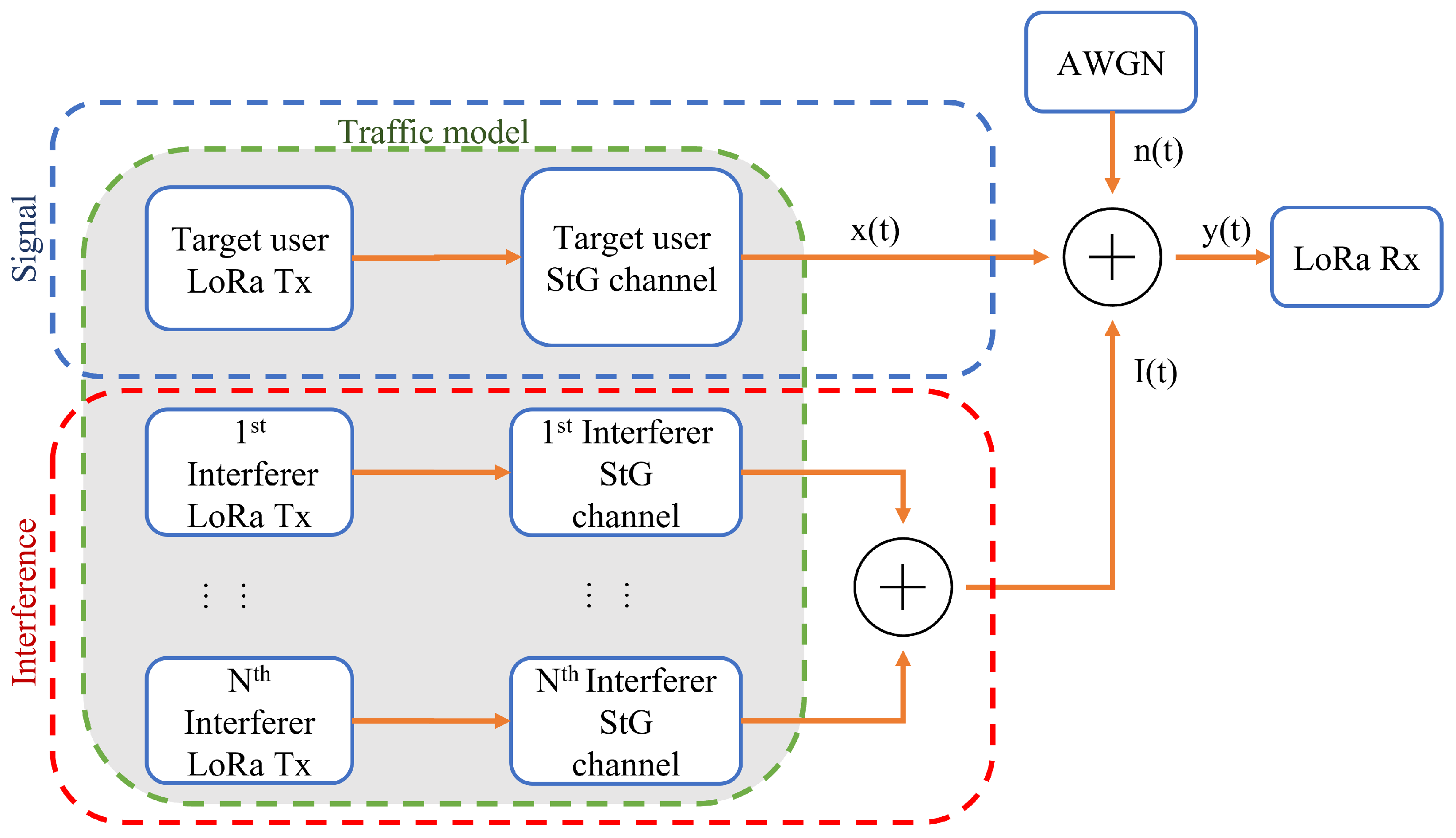
3.1. System Model
- Terrestrial IoT devices/sensors.
- Other IoT devices contributing to co-channel interference.
- Satellite constellation, where the satellites act as the gateway (base station).
3.1.1. Geometric Model-IoT Devices
3.1.2. Geometric Model—Satellite Availability
3.1.3. Satellite Constellation Model
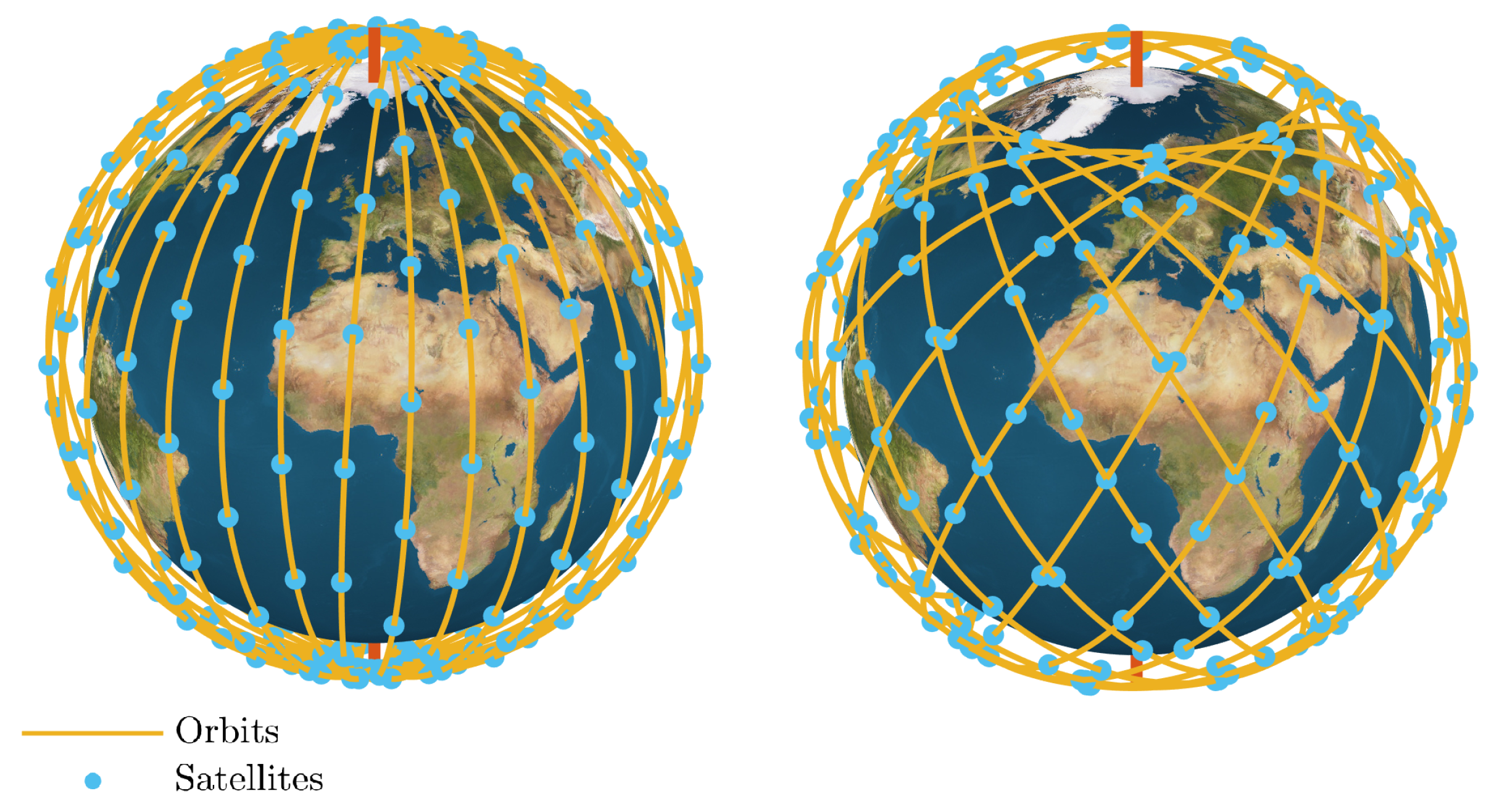
- Walker-Delta Constellation: The Walker-Delta constellation is widely adopted by many satellite projects, such as Starlink and Kupier [11,13]. Walker-Delta constellations reduce the variation in the inter-distances between satellites providing a denser distribution of satellites around the equator and mid-latitude locations [45], illustrated in Figure 5. In addition, Walker-Delta configuration enables the utilization of inter-satellite links (ISLs) facilitating communication between the different satellites in the constellation. In Walker-Delta the orbital planes are equally spaced and rotated around the earth rotational axis, with a right ascension of the ascending node angle (RAAN) .
- Walker-Star Constellation: The Walker-Star constellation is also widely adopted by current commercial satellite providers, such as Iridium and OneWeb [12,46]. Walker-Star constellations typically have their inclination angle, i, close to 90. This configuration enables true global availability where even the poles are provided coverage unlike Walker-Delta constellations. However, this comes at the cost of an unnecessarily high density of satellites at the poles along with slightly reduced density at the equator. Figure 5 shows a comparison between the availability of Walker-Delta and Walker-Star constellations, the altitude and number of satellites are intentionally reduced to show the variation in availability time. Such low availability is acceptable in delay-tolerant IoT applications, however broadband networks are designed with either larger higher altitudes and/or larger number of satellites in order to provide 100% coverage time. Another difference to the Walker-delta is that the orbital planes RAAN in Walker-Star are spread across the range 0 to instead of 0 to , i.e.,

| Parameters | Symbol | Simulation Value |
|---|---|---|
| Satellite constellation altitude | h | 550 [km] |
| Number of satellites | 480 | |
| Orbital planes | P | 16 |
| Phasing parameter | F | 8 |
| Density of IoT devices | 1.5625 [units per km] | |
| Earth’s radius | 6371 [km] | |
| Carrier frequency | fo †1 | 915 [MHz] |
| Transmit power | Pt | 27 [dBm] |
| Satellite antenna beamwidth | ψ | 80° |
| Satellite antenna Gain | G | 9 [dB] |
| Duty cycle †4 | ν | 1.45 × 10⁻⁴% |
| Bandwidth | B | 125 [kHz] |
| Noise power †5 | W | −115 [dBm] |
| LoS probability parameter | 0.4 | |
| LoS excess mean | 0 | |
| LoS excess standard deviation | 1 | |
| NLoS mean | 8 | |
| NLoS standard deviation | 10 | |
| LoRa spreading factor | SF | 7 |
| RF-to-electric conversion factor | 4 | |
| Overhead power per packet | 210 [mW] | |
| Overhead power due to sync. | 250 [mW] | |
| LoRa air time | 61.7 [ms] |
3.2. Interference and Channel Model
3.2.1. Free-Space Path-Loss and Excess Path-Loss
3.2.2. Doppler Shift Model
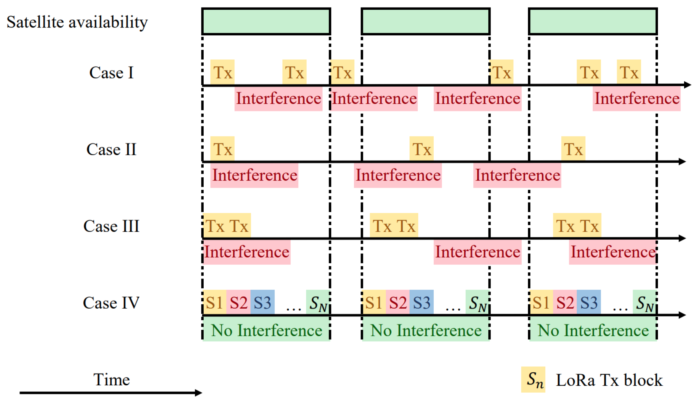
3.3. Access Models for IoT-over-Satellite
3.3.1. Case I: Pure-ALOHA
3.3.2. Case II: Scheduled Access
3.3.3. Case III: Scheduled Access with Packet Repetition
3.3.4. Case IV: Scheduled Round Robin Transmission
3.4. LoRa Emulator
3.4.1. LoRa Modulation
3.4.2. LoRa Demodulation
3.4.3. Energy Consumption
4. Emulation Results and Discussion
4.1. Impact of Satellite Constellation
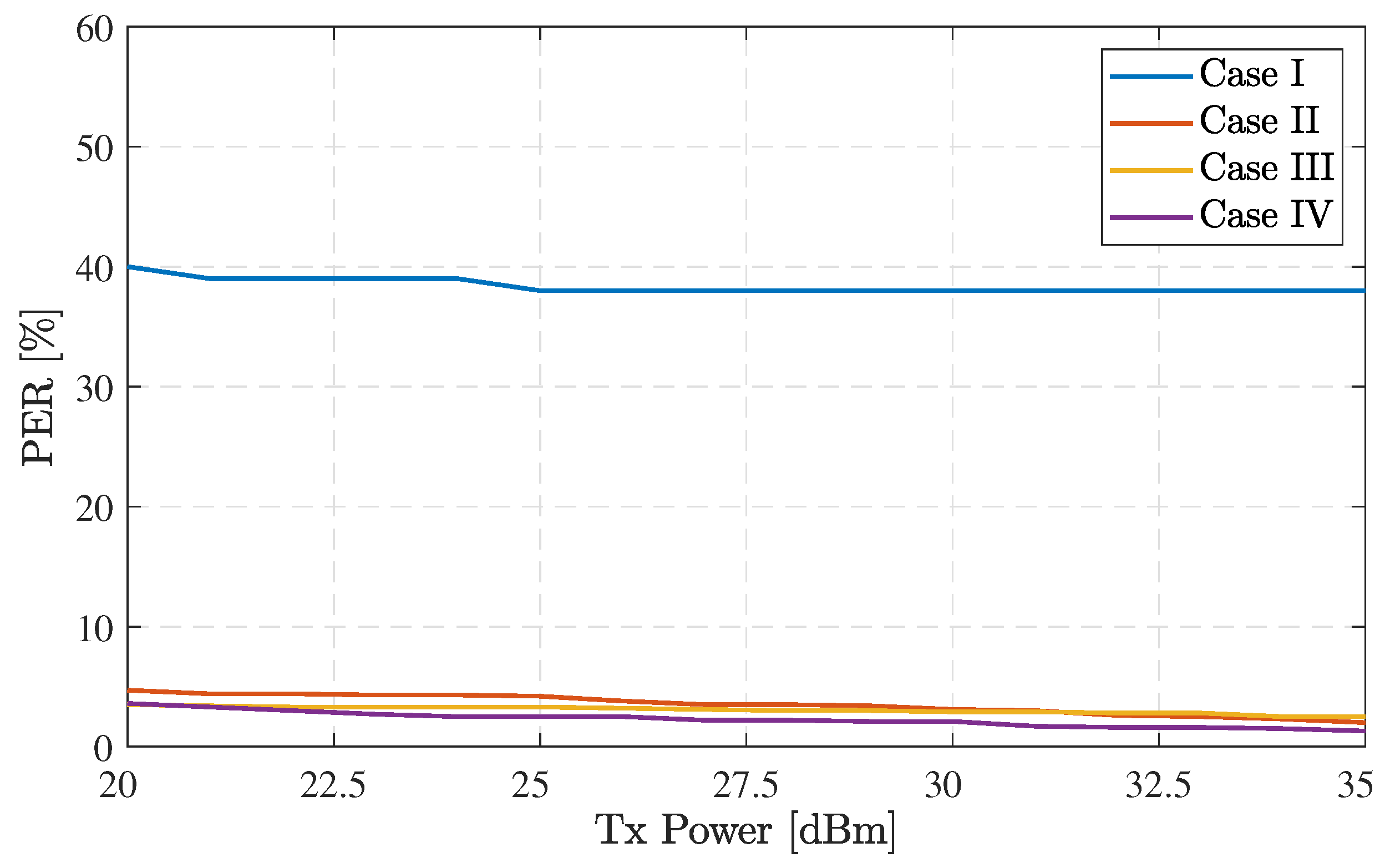
4.2. Access Methods Comparison
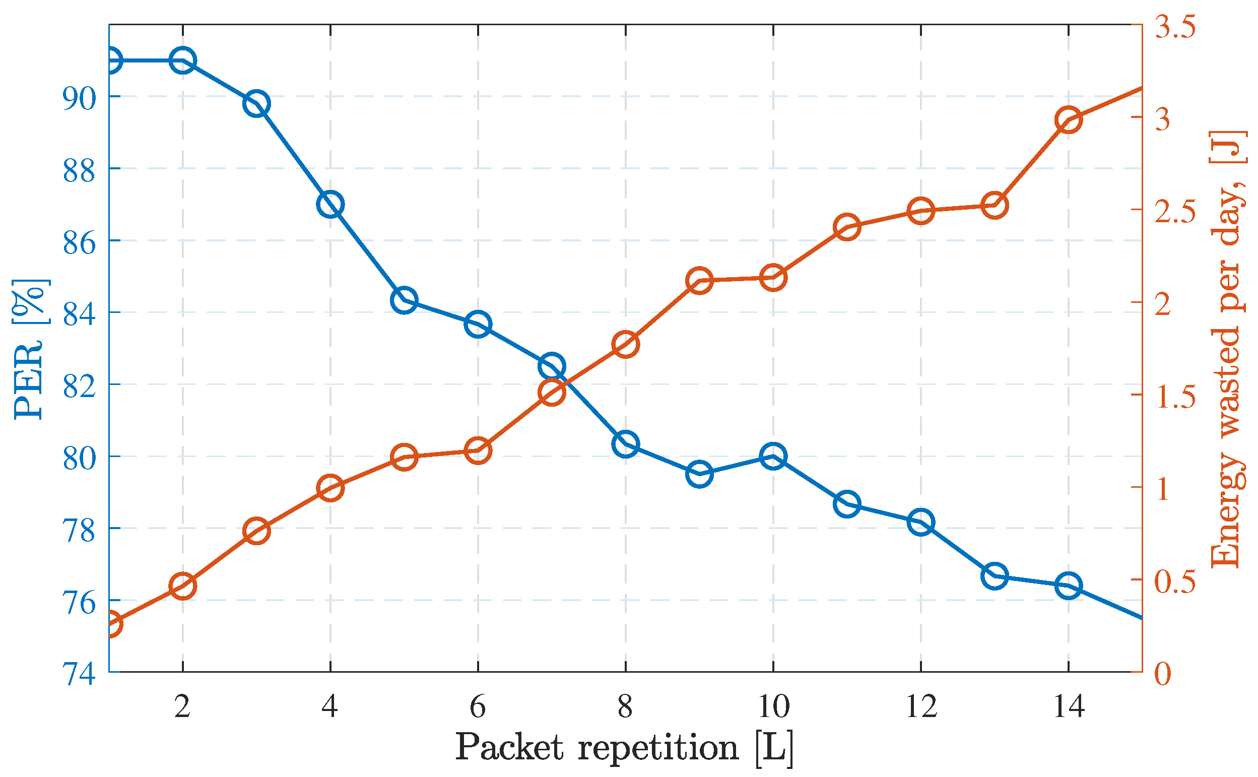
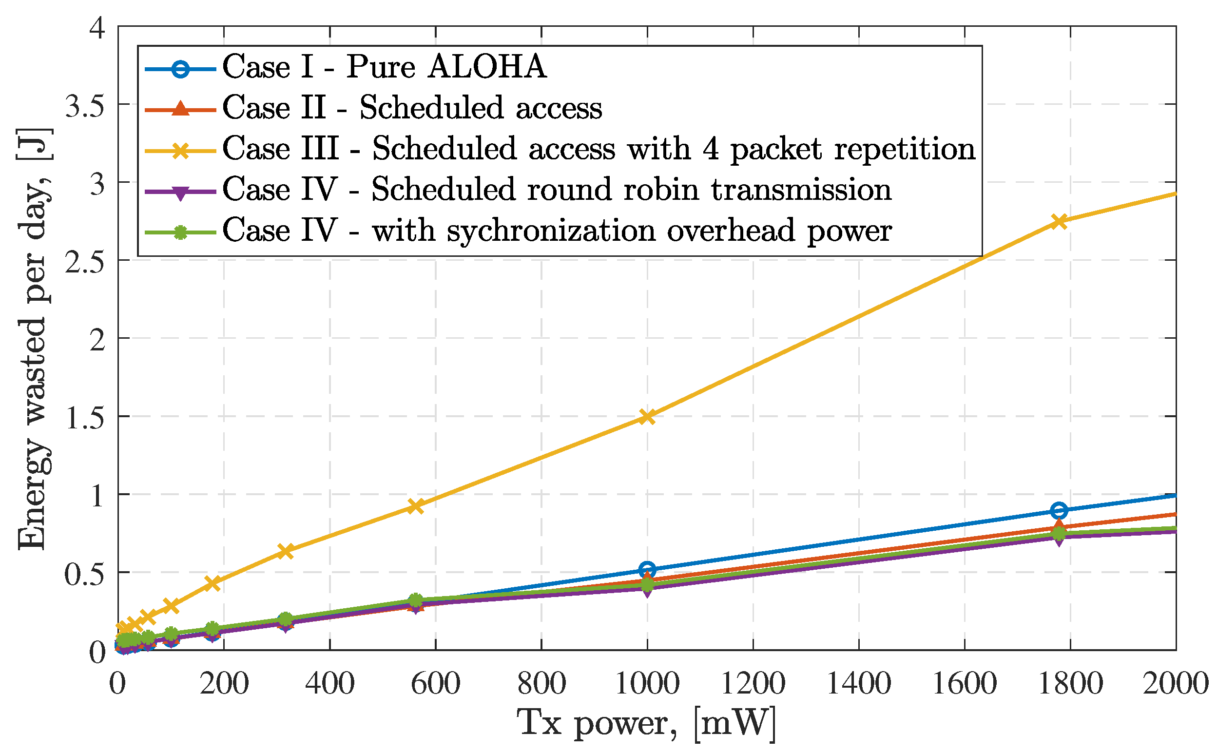
4.3. Energy Wasted in Different Access Methods
4.4. Feasibility of IoT-over-Satellite Using LoRa
5. Conclusions
Author Contributions
Funding
Data Availability Statement
Conflicts of Interest
References
- Byers, C.C. Architectural Imperatives for Fog Computing: Use Cases, Requirements, and Architectural Techniques for Fog-Enabled IoT Networks. IEEE Commun. Mag. 2017, 55, 14–20. [Google Scholar] [CrossRef]
- Ta-Shma, P.; Akbar, A.; Gerson-Golan, G.; Hadash, G.; Carrez, F.; Moessner, K. An Ingestion and Analytics Architecture for IoT Applied to Smart City Use Cases. IEEE Internet Things J. 2018, 5, 765–774. [Google Scholar] [CrossRef]
- Hanes, D.; Salgueiro, G.; Grossetete, P.; Barton, R.; Henry, J. IoT Fundamentals: Networking Technologies, Protocols, and Use Cases for the Internet of Things; Cisco Press: Indianapolis, IN, USA, 2017. [Google Scholar]
- Al Homssi, B.; Al-Hourani, A.; Magowe, K.; Delaney, J.; Tom, N.; Ying, J.; Wolf, H.; Maselli, S.; Kandeepan, S.; Wang, K.; et al. A Framework for the Design and Deployment of Large-Scale LPWAN Networks for Smart Cities Applications. IEEE Internet Things Mag. 2021, 4, 53–59. [Google Scholar] [CrossRef]
- Zhang, L.; Liang, Y.C.; Niyato, D. 6G Visions: Mobile Ultra-Broadband, Super Internet-of-Things, and Artificial Intelligence. China Commun. 2019, 16, 1–14. [Google Scholar] [CrossRef]
- Cioni, S.; De Gaudenzi, R.; Del Rio Herrero, O.; Girault, N. On the Satellite Role in the Era of 5G Massive Machine Type Communications. IEEE Netw. 2018, 32, 54–61. [Google Scholar] [CrossRef]
- Bacco, M.; Boero, L.; Cassara, P.; Colucci, M.; Gotta, A.; Marchese, M.; Patrone, F. IoT Applications and Services in Space Information Networks. IEEE Wirel. Commun. 2019, 26, 31–37. [Google Scholar] [CrossRef]
- De Sanctis, M.; Cianca, E.; Araniti, G.; Bisio, I.; Prasad, R. Satellite Communications Supporting Internet of Remote Things. IEEE Internet Things J. 2016, 3, 113–123. [Google Scholar] [CrossRef]
- 3GPP. Study on New Radio (NR) to Support Non-Terrestrial Networks; Technical Report TR38.811; 3rd Generation Partnership Project (3GPP); 3GPP: Sophia Antipolis, France, 2020. [Google Scholar]
- 3GPP. Solutions for NR to support Non-Terrestrial Networks (NTN); Technical Report TR38.821; 3rd Generation Partnership Project (3GPP); 3GPP: Sophia Antipolis, France, 2021. [Google Scholar]
- Starlink. Starlink. Available online: https://www.starlink.com/ (accessed on 24 July 2022).
- OneWeb. OneWeb. Available online: https://oneweb.net/ (accessed on 24 July 2022).
- Amazon.com, Inc. Project Kuiper. Available online: https://www.aboutamazon.com/news/tag/project-kuiper (accessed on 24 July 2022).
- Deckett, M. ORBCOMM—A Description and Status of the LEO Satellite Mobile Data Communication System. In Proceedings of the 15th International Communicatons Satellite Systems Conference and Exhibit. 2012. Available online: https://arc.aiaa.org/doi/pdf/10.2514/6.1994-1135 (accessed on 24 July 2022). [CrossRef]
- Myriota. Myriota. Available online: https://myriota.com/ (accessed on 24 July 2022).
- Technologies, F.S. Fleet Space Technologies. Available online: https://fleetspace.com/ (accessed on 24 July 2022).
- Gaber, A.; ElBahaay, M.A.; Maher Mohamed, A.; Zaki, M.M.; Samir Abdo, A.; AbdelBaki, N. 5G and Satellite Network Convergence: Survey for Opportunities, Challenges and Enabler Technologies. In Proceedings of the 2020 2nd Novel Intelligent and Leading Emerging Sciences Conference (NILES), Giza, Egypt, 24–26 October 2020; pp. 366–373. [Google Scholar] [CrossRef]
- Qu, Z.; Zhang, G.; Cao, H.; Xie, J. LEO Satellite Constellation for Internet of Things. IEEE Access 2017, 5, 18391–18401. [Google Scholar] [CrossRef]
- Al Homssi, B.; Al-Hourani, A.; Wang, K.; Conder, P.; Sithamparanathan, K.; Choi, J.; Allen, B.; Moores, B. Next Generation Mega Satellite Networks for Access Equality: Opportunities, Challenges, and Performance. IEEE Commun. Mag. 2022, 60, 18–24. [Google Scholar] [CrossRef]
- Sornin, N.; Luis, M.; Eirich, T.; Kramp, T.; Hersent, O. LoRaWAN Specification; LoRa Alliance: Amsterdam, The Netherlands, 2015. [Google Scholar]
- Fraire, J.A.; Henn, S.; Dovis, F.; Garello, R.; Taricco, G. Sparse Satellite Constellation Design for LoRa-based Direct-to-Satellite Internet of Things. In Proceedings of the GLOBECOM 2020—2020 IEEE Global Communications Conference, Taipei, Taiwan, 7–11 December 2020; pp. 1–6. [Google Scholar] [CrossRef]
- Chiti, F.; Fantacci, R.; Pierucci, L. Energy Efficient Communications for Reliable IoT Multicast 5G/Satellite Services. Future Internet 2019, 11, 164. [Google Scholar] [CrossRef]
- Marchese, M.; Moheddine, A.; Patrone, F. IoT and UAV Integration in 5G Hybrid Terrestrial-Satellite Networks. Sensors 2019, 19, 3704. [Google Scholar] [CrossRef]
- Cluzel, S.; Franck, L.; Radzik, J.; Cazalens, S.; Dervin, M.; Baudoin, C.; Dragomirescu, D. 3GPP NB-IOT Coverage Extension Using LEO Satellites. In Proceedings of the 2018 IEEE 87th Vehicular Technology Conference (VTC Spring), Porto, Portugal, 3–6 June 2018; pp. 1–5. [Google Scholar] [CrossRef]
- Janhunen, J.; Ketonen, J.; Hulkkonen, A.; Ylitalo, J.; Roivainen, A.; Juntti, M. Satellite Uplink Transmission with Terrestrial Network Interference. In Proceedings of the 2015 IEEE Global Communications Conference (GLOBECOM), San Diego, CA, USA, 6–10 December 2015; pp. 1–6. [Google Scholar] [CrossRef]
- Hofmann, C.A.; Knopp, A. Ultranarrowband Waveform for IoT Direct Random Multiple Access to GEO Satellites. IEEE Internet Things J. 2019, 6, 10134–10149. [Google Scholar] [CrossRef]
- Qian, Y.; Ma, L.; Liang, X. The Performance of Chirp Signal Used in LEO Satellite Internet of Things. IEEE Commun. Lett. 2019, 23, 1319–1322. [Google Scholar] [CrossRef]
- Bhave, P.; Fines, P. System Behavior and Improvements for M2M Devices Using an Experimental Satellite Network. In Proceedings of the 2015 IEEE Region 10 Symposium, Ahmedabad, India, 13–15 May 2015; pp. 13–16. [Google Scholar] [CrossRef]
- Bacco, M.; Colucci, M.; Gotta, A. Application Protocols Enabling Internet of Remote Things via Random Access Satellite Channels. In Proceedings of the 2017 IEEE International Conference on Communications (ICC), Paris, France, 21–25 May 2017; pp. 1–6. [Google Scholar] [CrossRef] [Green Version]
- Manzoor, B.; Homssi, B.A.; Al-Hourani, A.; Kandeepan, S. Optimal Repetition Rate for Maximal Coverage. IEEE Wirel. Commun. Lett. 2021, 10, 800–804. [Google Scholar] [CrossRef]
- Manzoor, B.; Homssi, B.A.; Al-Hourani, A. IoT Coverage Enhancement using Repetition in Energy Constrained Devices: An Analytic Approach. IEEE Trans. Green Commun. Netw. 2021, 6, 1122–1131. [Google Scholar] [CrossRef]
- Bacco, M.; Cassarà, P.; Colucci, M.; Gotta, A. Modeling Reliable M2M/IoT Traffic Over Random Access Satellite Links in Non-Saturated Conditions. IEEE J. Sel. Areas Commun. 2018, 36, 1042–1051. [Google Scholar] [CrossRef]
- Ferrer, T.; Céspedes, S.; Becerra, A. Review and Evaluation of MAC Protocols for Satellite IoT Systems Using Nanosatellites. Sensors 2019, 19, 1947. [Google Scholar] [CrossRef]
- Clazzer, F.; Munari, A. IoT via Satellite: Asynchronous Random Access for the Maritime Channel. In Proceedings of the 2020 IEEE 91st Vehicular Technology Conference (VTC2020-Spring), Antwerp, Belgium, 25–28 May 2020; pp. 1–6. [Google Scholar] [CrossRef]
- Krondorf, M.; Goblirsch, M.; de Gaudenzi, R.; Cocco, G.; Toptsidis, N.; Acar, G. Towards the Implementation of Advanced Random Access Schemes for Satellite IoT. Int. J. Satell. Commun. Netw. 2020, 38, 177–199. [Google Scholar] [CrossRef]
- De Gaudenzi, R.; Del Rio Herrero, O.; Gallinaro, G.; Cioni, S.; Arapoglou, P.D. Random access schemes for satellite networks, from VSAT to M2M: A survey. Int. J. Satell. Commun. Netw. 2018, 36, 66–107. [Google Scholar] [CrossRef]
- Chan, C.C.; Al-Hourani, A.; Choi, J.; Gomez, K.M.; Kandeepan, S. Performance Modeling Framework for IoT-over-Satellite Using Shared Radio Spectrum. Remote Sens. 2020, 12, 1666. [Google Scholar] [CrossRef]
- Al-Hourani, A. Optimal Satellite Constellation Altitude for Maximal Coverage. IEEE Wirel. Commun. Lett. 2021, 10, 1444–1448. [Google Scholar] [CrossRef]
- Talgat, A.; Kishk, M.A.; Alouini, M.S. Stochastic Geometry-Based Analysis of LEO Satellite Communication Systems. IEEE Commun. Lett. 2021, 25, 2458–2462. [Google Scholar] [CrossRef]
- Homssi, B.A.; Al-Hourani, A. Modeling Uplink Coverage Performance in Hybrid Satellite-Terrestrial Networks; IEEE: Piscataway, NJ, USA, 2021. [Google Scholar] [CrossRef]
- Chan, C.C.; Al-Hourani, A.; Homssi, B.A. Performance Evaluation of Random Access Methods for IoT-over-Satellite. Available online: https://github.com/s3556682/Performance-Evaluation-of-Random-Access-Methods-for-IoT-over-Satellite (accessed on 24 July 2022).
- Al Homssi, B.; Dakic, K.; Maselli, S.; Wolf, H.; Kandeepan, S.; Al-Hourani, A. IoT Network Design Using Open-Source LoRa Coverage Emulator. IEEE Access 2021, 9, 53636–53646. [Google Scholar] [CrossRef]
- Manzoor, B.; Al-Hourani, A.; Homssi, B.A.; Magowe, K.; Kandeepan, S.; Chavez, K.G. Evaluating Coverage Performance of NB-IoT in the ISM-band. In Proceedings of the 2020 27th International Conference on Telecommunications (ICT), Bali, Indonesia, 5–7 October 2020; pp. 1–5. [Google Scholar] [CrossRef]
- Al-Hourani, A. A Tractable Approach for Predicting Pass Duration in Dense Satellite Networks. IEEE Commun. Lett. 2021, 25, 2698–2702. [Google Scholar] [CrossRef]
- Savitri, T.; Kim, Y.; Jo, S.; Bang, H. Satellite Constellation Orbit Design Optimization with Combined Genetic Algorithm and Semianalytical Approach. Int. J. Aerosp. Eng. 2017, 2017, 1235692. [Google Scholar] [CrossRef]
- Maine, K.; Devieux, C.; Swan, P. Overview of IRIDIUM Satellite Network. In Proceedings of the WESCON’95, San Francisco, CA, USA, 7–9 November 1995; p. 483. [Google Scholar] [CrossRef]
- Al-Hourani, A.; Guvenc, I. On Modeling Satellite-to-Ground Path-Loss in Urban Environments. IEEE Commun. Lett. 2020, 25, 696–700. [Google Scholar] [CrossRef]
- Al Homssi, B.; Al-Hourani, A.; Chandrasekharan, S.; Gomez, K.M.; Kandeepan, S. On the Bound of Energy Consumption in Cellular IoT Networks. IEEE Trans. Green Commun. Netw. 2020, 4, 355–364. [Google Scholar] [CrossRef]
- Wu, T.; Qu, D.; Zhang, G. Research on LoRa Adaptability in the LEO Satellites Internet of Things. In Proceedings of the 2019 15th International Wireless Communications Mobile Computing Conference (IWCMC), Tangier, Morocco, 24–28 June 2019; pp. 131–135. [Google Scholar] [CrossRef]
- Laya, A.; Kalalas, C.; Vazquez-Gallego, F.; Alonso, L.; Alonso-Zarate, J. Goodbye, ALOHA! IEEE Access 2016, 4, 2029–2044. [Google Scholar] [CrossRef] [Green Version]
- Bai, K.; Zhang, J. Opportunistic Multichannel ALOHA: Distributed Multiaccess Control Scheme for OFDMA Wireless Networks. IEEE Trans. Veh. Technol. 2006, 55, 848–855. [Google Scholar] [CrossRef]
- Xue, Y.; Kaiser, T.; Gershman, A.B. Channel-Aware ALOHA-Based OFDM Subcarrier Assignment in Single-Cell Wireless Communications. IEEE Trans. Commun. 2007, 55, 953–962. [Google Scholar] [CrossRef]
- Croce, D.; Gucciardo, M.; Mangione, S.; Santaromita, G.; Tinnirello, I. Impact of LoRa Imperfect Orthogonality: Analysis of Link-Level Performance. IEEE Commun. Lett. 2018, 22, 796–799. [Google Scholar] [CrossRef] [Green Version]


Publisher’s Note: MDPI stays neutral with regard to jurisdictional claims in published maps and institutional affiliations. |
© 2022 by the authors. Licensee MDPI, Basel, Switzerland. This article is an open access article distributed under the terms and conditions of the Creative Commons Attribution (CC BY) license (https://creativecommons.org/licenses/by/4.0/).
Share and Cite
Chan, C.C.; Al Homssi, B.; Al-Hourani, A. Performance Evaluation of Random Access Methods for IoT-over-Satellite. Remote Sens. 2022, 14, 4232. https://doi.org/10.3390/rs14174232
Chan CC, Al Homssi B, Al-Hourani A. Performance Evaluation of Random Access Methods for IoT-over-Satellite. Remote Sensing. 2022; 14(17):4232. https://doi.org/10.3390/rs14174232
Chicago/Turabian StyleChan, Chiu Chun, Bassel Al Homssi, and Akram Al-Hourani. 2022. "Performance Evaluation of Random Access Methods for IoT-over-Satellite" Remote Sensing 14, no. 17: 4232. https://doi.org/10.3390/rs14174232
APA StyleChan, C. C., Al Homssi, B., & Al-Hourani, A. (2022). Performance Evaluation of Random Access Methods for IoT-over-Satellite. Remote Sensing, 14(17), 4232. https://doi.org/10.3390/rs14174232