Abstract
The BeiDou Navigation Satellite System (BDS) is fully operational and provides positioning, navigation, and timing services to users worldwide. To comprehensively evaluate the BeiDou-3 Navigation Satellite System (BDS-3) global real-time kinematic (RTK) positioning performance, five sets of IGS/MEGX stations with different baseline lengths are selected in this research, and the visibility of current BDS-3, BDS-2+BDS-3, and Global Positioning System (GPS) system satellites are analyzed. The single frequency, dual-frequency, and triple-frequency positioning accuracy as well as ambiguity fixing rate under short baseline and long baseline are also analyzed. The experimental results show that the positioning accuracies of B1C, BII, L1, and B3I single-frequency bands were about the same, while for band B2a it was lower. For the short baseline dual-frequency RTK positioning mode, the accuracy of BDS-3 (B1C/B2a), BDS-3 (B1I/B3I), triple-frequency BDS-3 (B1C/B2a/B3I), and GPS (L1L2) is comparable and slightly better than that of BDS-3 (B1I/B3I). With the increase in baseline length, the advantages of dual-frequency BDS-3 (B1C/B2a) and triple frequency BDS (B1C/B2a/B3I) are more obvious, with triple-frequency BDS-3 (B1C/B2a/B3I) having the best positioning accuracy. In terms of ambiguity fixing performance, dual-frequency BDS-2+BDS-3 (B1I/B3I) and dual-frequency GPS (L1L2) have the highest ambiguity fixing rate. The ambiguity fixing rate of dual-frequency BDS-3 (B1C/B2a) and triple-frequency BDS-3 (B1C/B2a/B3I) can be higher than 90% within 100 km. In the case of positioning using only the BDS-3 system, the triple-frequency BDS-3 (B1C/B2a/B3I) is superior to both the dual-frequency BDS-3 (B1I/B3I) and dual-frequency BDS-3 (B1C/B2a) in terms of both positioning accuracy and ambiguity fixing rate. The BDS-2+BDS-3 (B1I/B3I) dual-frequency RTK, which has reached a level comparable to GPS, can provide global users with real-time centimeter-level differential positioning services.
1. Introduction
The BDS is a global satellite navigation system built and operated independently by China, which combines navigation, positioning, communication, timing, and velocity measurement functions [1]. The development of the BDS is divided into three steps: a validation system, an extended regional navigation system, and a global navigation system [2]. As of July 2020, the BDS-1, BDS-2, and BDS-3 global satellite navigation systems have been completed successively. The BDS-3 consists of 30 satellites, including three geostationary earth orbit (GEO) satellites, three inclined geo-synchronous orbit (IGSO) satellites, and 24 medium earth orbit (MEO) satellites [3]. What BDS-3 differs from BDS-2 is in that it retains the B1I and B3I frequencies of BDS-2 while adding two new frequencies, B1C and B2a. For the B2I frequency point of BDS-2, the BDS-3 system changes its modulation type, keeping the frequency unchanged, and changes it to the B2b frequency. Compared with the BDS-2 satellite’s signal, B1C/B2a has better signal strength, and the Carrier-to-Noise density ratio () of the B2a signal is about 3 dB higher than other signals. The code observation accuracy of B1C/B2a is about 0.05 m higher than that of the traditional B1/B2/B3 signal; especially, that of B2a is better than 0.15 m. The double-differenced (DD) results of the zero-baseline show that the observation accuracy of B1C/L1/E1/L1 (QZSS) is between 1.2 and 1.4 mm and that of B2a/L5/E5A/L5 is slightly worse, between 1.3 and 1.6 mm, which is consistent with the results of the zero-baseline solution [4].
With the continuous improvement and development of the BDS-3 global navigation satellite system, many researchers have carried out relevant research on RTK positioning of new BDS-3 frequencies. At the short baseline RTK positioning level, Miao et al. [5] mainly studied the stochastic modeling and positioning performance of BDS-2 and BDS-3. Based on the established stochastic model, the performance of BDS-2 and BDS-3 RTK positioning was analyzed. The results show that for BDS-3 dual-frequency positioning, the positioning errors are several centimeters both on an ultra-short baseline and a short baseline, which is analogous to the BDS-2 dual-frequency positioning. Yuan et al. [6] analyzed the BDS-3-only RTK positioning using the data collected in zero and short baselines, they found that the positioning accuracies of B1C, B1I, and B3I single-frequencies were about the same, while that for frequency B2a was lower. In addition, the positioning results for dual-frequency combinations are not always better than those for single-frequency because of the absence of a good stochastic model.
At the long baseline RTK positioning level, the difference between the interpolated ionospheric corrections and the real ionospheric delay in the user’s data can be too large and may hamper a fast estimation of the integer ambiguities. Odijk [7] proposed that a way to improve this performance is to weight the ionospheric corrections in the adjustment of the observations, instead of treating them in a deterministic way over medium distances. Takasu et al. [8] developed a new strategy for such long baseline RTK applicable to up to 1000 km baselines. The strategy consists of an EKF-based parameter estimator without generating any linear combination of the measurements. The strategy also includes the integer ambiguity resolution in carrier-phase measurements with the partial fixing feature and tight constraints to once fixed integer ambiguities. Shu et al. [9] analyzed the factors affecting the precision of BDS medium-long baseline RTK; thereafter, 15 baselines ranging from 38 km to 167 km in different troposphere conditions are processed to assess the performance of relative ZTD-constrained RTK. They found that the troposphere parameter is difficult to distinguish from the height component, even with long time filtering for BDS-only RTK.
Since B1C/B2a has better signal strength, it is worth further analyzing the positioning performance of B1C/B2a dual-frequency RTK under different baselines compared with other GNSS signals. The evaluation of RTK positioning performance of the new BDS-3 frequencies under different baseline lengths can enhance our understanding of BDS positioning performance and provide a basis for multi-frequency and multi-system combination positioning, thereby improving the positioning performance. Therefore, in this research, we use BDS and GPS data to systematically compare the positioning performance of different systems at different frequencies under different baseline lengths. The rest of this paper is organized as follows: Section 2 introduces the RTK algorithm under different baseline lengths; Section 3 describes the data collection and processing strategies; Section 4 analyzes the performance of multi-GNSS multi-frequency RTK in terms of satellites number, PDOP values, positioning accuracy, ratio values, and the time to first fix (TTFF) of ambiguity. Finally, the results of this research are specifically summarized in the conclusion.
2. Multi-Frequency RTK Positioning Mathematical Model
2.1. RTK Double-Differenced Measurement Model
Under the short baseline RTK positioning mode, the DD observation model can effectively attenuate the satellite ephemeris error, atmospheric delay error, receiver clock bias, receiver hardware delay, and preserve the integer value of the DD ambiguity [10]. The BDS/GPS DD carrier phase and pseudorange observations can be expressed as:
In Equation (1), , represent the base-station and the rover station; , represent the reference and non-reference satellites; is the DD symbol; and are the code and carrier phase observations; is the geometry distance between the receiver and satellite; is the wavelength; denotes the carrier phase ambiguity; and denote the observation noise of DD carrier and pseudorange.
For the long baseline (>20 km) RTK positioning mode, the tropospheric and ionospheric errors are difficult to eliminate. Therefore, the BDS/GPS DD carrier-phase and pseudorange observations are expressed as:
In Equation (2), is the slant troposphere delay; represents the slant ionosphere delay.
By using the triple-frequency signal, more combined observations can be obtained to enhance the strength of observation equations [11]. Considering the ionospheric and tropospheric efforts, the DD observation equations of combined triple-frequency pseudorange and phase are:
In Equation (3), . The triple-frequency observations enhance the strength of the observation model, avoid noise amplification, and shorten the convergence time, which greatly improves the success rate and reliability of ambiguity fixing.
2.2. Kalman Filtering Theory for Short Baseline RTK
Kalman Filtering (KF) is a linear filtering method based on the principle of linear unbiased minimum variance estimation for filtering. By introducing the idea of state equation, the new state parameters are recursively derived from the state valuation of the previous epoch combined with the observed values of the current epoch in a state transfer matrix. The Kalman Filtering is mainly divided into two parts: state prediction and parameter updating. For epoch n − 1 and n, the prediction models for the state parameters and covariance matrix are as follows [12]:
where and are the estimated state vector and its covariance matrix and and are the transition matrix and the covariance matrix of the system noise. In short baseline RTK positioning mode, is defined as:
where and are the three-dimensional position vector and velocity of the rover station and is the DD carrier-phase biases in cycle. The parameter update portion of the Kalman Filter is as follows:
where K is the Kalman Gain matrix, G is the design matrix, and R is the covariance matrix of the observations. The variance of single-difference observations is usually calculated first from the elevation of the satellite or signal-to-noise ratio (SNR), and the covariance matrix of DD measurements can be obtained under the law of error propagation. The measurement vector y is also defined by DD carrier-phase and pseudorange measurement as [8]:
where:
In Equations (11) and (12), and are the DD carrier-phase and pseudorange.
2.3. Kalman Filtering Theory for Long Baseline RTK Positioning
2.3.1. Double-Differenced Ionosphere Model
The propagation speed of electromagnetic wave signals changes as they pass through the ionosphere, and the degree of change depends mainly on the electron density and signal frequency in the ionosphere [10]. The initial value of the ionosphere delay can be corrected by using the Klobuchar model, and the residual part can be estimated as an unknown parameter in Kalman Filtering. The ionosphere delay between different satellites is usually considered to be uncorrelated. The DD ionosphere is generally defined as:
In Equation (13), is the zenith ionosphere delay; is the elevation of the satellite; is the mapping function. Taking the average of the mapping functions of the rover and the base-station, Equation (13) can be converted as:
where:
2.3.2. Double-Differenced Troposphere Model
Troposphere delays are divided into hydrostatic delay and wet delay. Hydrostatic delay accounts for 90% of the zenith total delay and can be calculated by modelling with an accuracy of millimeter level. The wet delay accounts for 10% of the zenith total delay, and it is difficult to calculate the wet delay by an accurate correction model because of the large variation in water vapor in the atmosphere [13]. Therefore, in long baseline RTK positioning, the hydrostatic delay is calculated by the Saastamoinen model, and the hydrostatic mapping function is calculated by the Neill Mapping Function. For the residual wet tropospheric delay, it can be estimated as an unknown parameter in Kalman Filtering. The DD residual wet tropospheric delay is defined as:
In Equation (15), is the zenith troposphere wet delay, is the elevation of the satellite, and is the wet mapping function. Since the single-differenced tropospheric wet delay of satellites is strongly correlated and a set of single-difference tropospheric wet delays can usually be used to estimate the single-difference combination of all visible satellites, then Equation (15) can be rewritten as:
where:
2.3.3. Settings in Kalman Filtering for Long Baseline RTK Positioning
In long-baseline (>20 km) RTK positioning, the troposphere and ionosphere are difficult to eliminate. Therefore, the DD troposphere wet delay and DD ionosphere delay of the long baseline are regarded as unknowns for parameter estimation, which is added in the Kalman Filtering as random walk parameters [8].
In Equation (17), is the DD zenith ionospheric delay and is the DD troposphere delay.
The level of the troposphere error is related to the length of the baseline and the elevation difference between stations. Therefore, the zenith troposphere constraint and random walk noise are applied as follows [14]:
In Equations (18) and (19), D is the baseline length, H is the height difference in meter, and is the epoch time difference in second.
The magnitude of the ionosphere error is not only related to the baseline length and the elevation difference between the base and rover stations, but also closely related to the station latitude. Therefore, the ionospheric constraints and random walk noise are applied as follows [14]:
where lat is the average latitude of the two stations and E is the elevation of the satellite.
2.4. Integer Ambiguity Resolution
Once the estimated states obtained are updated in the Kalman Filtering, the float solutions can be obtained in RTK positioning. The fixed solution can be derived by the least-square ambiguity decorrelation adjustment (LAMBDA) method. The solution process for the fixed solution is mathematically a mixed-integer least squares problem. The parameters to be solved are partly float values and partly integers.
where represents the most appropriate integer vector, is the float carrier-phase ambiguities, and and are the integer ambiguities and their covariance. and are the fixed and the float solution of the rover antenna position, respectively
is the ambiguities and coordinates covariance matrix. In order to increase the ambiguity fixing rate and shorten the ambiguity fixing time, a partial fixing strategy is introduced in this research. A partial subset is selected for fixation in the full set of ambiguity according to a certain criterion. Generally, the elevation of the satellite is used as the selection criterion, and if the satellite’s elevation is lower than the pre-set threshold, its ambiguity is not fixed. The ambiguity of satellites with elevations greater than the threshold is selected and arranged in ascending order of the variance of the original ambiguity parameters to form a new ambiguity subset [15].
The ratio-factor ratio, defined as the ratio of the weight sum of the squared residuals by the second-best solution to one by the best , is used to check the reliability of the solution. It characterizes how close the floating-point solution is to the optimal integer vector [16].
where k is an empirically given constant, which is usually set to 3.
To evaluate the RTK performance, the ambiguity resolution fixing rate is defined as follows [14]:
where is the correct fixed solution number and n is the total epoch number. The correct fixed solution implies that the ratio value is higher than 3.0.
3. Data Collection and Processing Strategies
In this paper, five groups of IGS/MEGX stations with different baseline lengths which can receive BDS-3 multi-frequency observations were selected, using data from DOY215 (3 August 2020) to DOY221 (9 August 2020) for a total of 7 days with a sampling interval of 30 s and a total of 2880 epochs per day. The distribution of the stations is shown in Figure 1 (Since METG and MET3 are too far away to be displayed on the map, they are inserted into the top left corner of the map). Receivers and antenna types of these stations are specified in Table 1.
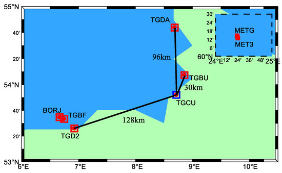
Figure 1.
Distribution of the selected IGS/MGEX station.

Table 1.
Information of the selected stations.
The stations were selected to form baselines of different lengths to be solved, and the specific information is shown in Table 2. Data processing of the screened stations was performed using the Net_Diff [17] software developed at the GNSS Analysis Center of Shanghai Astronomical Observatory (http://center.shao.ac.cn/shao_gnss_ac/ (accessed on 11 March 2022)), the elevation fixed weight was selected by the weight ratio strategy, and the mean value of the three-day precise point positioning (PPP) solution was used as the true value. The satellite visibility (the number of satellites, position dilution of precision (PDOP)), ratio (the ratio of the residual quadratic of the next best integer solution to the residual quadratic of the best solution), positioning accuracy (root mean square (RMS)), and time to first fix (TTFF) of the ambiguities are analyzed. The specific data processing strategies are shown in Table 3.

Table 2.
Baseline information.

Table 3.
Date processing strategy.
4. Multi-Frequency RTK Positioning Accuracy Analysis
4.1. Number of Satellites and PDOP Values
The number of visible satellites refers to the number of satellites that can be observed by the rover and base-station at the same time. The increase in visible satellites can improve the ambiguity fixing rate and shorten the ambiguity correct fixing time, which is an important factor affecting the positioning accuracy. The PDOP value can express the satellite geometric configuration, and the smaller its value, the better the degree of satellite distribution and the higher the positioning accuracy [19]. Positioning analyses were performed for the baseline TGBU-TGCU on DOY221 data, and the number of satellites and PDOP values is shown in Figure 2.
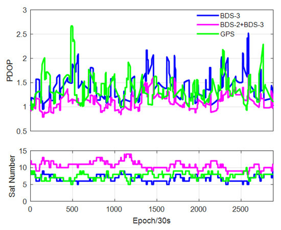
Figure 2.
Number of available satellites and PDOP value.
From Figure 2, the number of available satellites of BDS-2+BDS-3 varies between 8 and 14, while the number of available satellites of BDS-3 varies between 5 and 9, and the number of available satellites of GPS varies between 5 and 10. The PDOP value of BDS-2+BDS-3 is stable between 0.5 and 1.5, while the PDOP value of GPS and BDS-3 varies between 1 and 3 and is greater than BDS-2+BDS-3. It shows that the current number of available satellites and satellite geometry of BDS-2+BDS-3 is significantly better than GPS and the satellite geometry of BDS-3 is roughly equivalent to GPS.
4.2. Positioning Accuracy
Single-frequency low-cost receivers have the advantages of low price and small size and are widely used in vehicle navigation, precision agriculture, and other industries. Therefore, it is necessary to evaluate the positioning performance of BDS-3 single-frequency RTK. According to the experimental parameter settings in Table 2 and Table 3, for the five groups of stations with different baseline lengths, we use the data from DOY215 (3 August 2020) to DOY221 (9 August 2020) for a total of seven days. The RMS in the three directions of East (E), North (N), and Up (U) were calculated, and the RMS in the three directions as well as the ambiguity fixing rates were averaged over the seven days of data.
To analyze the BDS-3 (BIC) single-frequency RTK positioning performance, the continuous [18] ambiguity fixing strategy was chosen based on the baseline BORJ–TGBF (6 km) in the positioning mode of short baseline RTK (If not specifically stated, the continuous ambiguity fixing strategy is the default in this research). The RMS comparisons for the five frequencies of BDS-3 (B1C), BDS-3 (B2a), BDS-2+BDS-3 (B1I), BDS-2+BDS-3 (B3I), and GPS (L1) are shown in Figure 3, and the seven days of RMS and ambiguity fixing rates are averaged in Table 4. Due to the fewer visible satellites and poorer geometry distribution of BDS-3, the ambiguity fixing rate of B1C and B2a is lower than that of L1, B1I, and B3I. The positioning accuracies of single-frequency bands B1C, BII, L1, and B3I were about the same, while the accuracy was lower for band B2a. The short baseline configuration enables the single-differencing between the receivers to eliminate the errors related to satellites and the atmosphere. Therefore, we attributed the poor positioning performance for the single-frequency band B2a to its poor signal quality [4,6,20]. In DOY221, the fact that BDS-3 has only four satellites in multiple epochs results in poor positioning accuracy for B1C and B2a in that period.
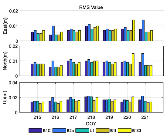
Figure 3.
BORJ–TGBF (6 km) single frequency short baseline RTK positioning accuracy.

Table 4.
BORJ–TGBF (6 km) average of short baseline RTK RMS and ambiguity fixing rate.
The single epoch RTK ambiguity fixing rate is one of the important indicators to evaluate the RTK performance. In short baseline RTK positioning mode, the instantaneous [18] and continuous ambiguity fixing strategies were chosen on baseline METG–MET3 (3 km) for BDS-3 (B1C/B2a), BDS-2+BDS-3 (B1I/B3I), GPS (L1L2), BDS-3 (B1C/B2a/B3I), and BDS-3 (B1I/B3I). Results for the five frequencies are shown in Figure 4; the means of RMS and ambiguity fixing rates for the seven days are shown in Table 5.
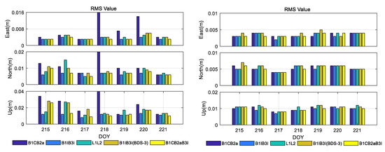
Figure 4.
METG–MET3 (3 km) instantaneous short baseline RTK positioning accuracy. The left subplot shows the instantaneous ambiguity fixing strategy, and the right subplot shows the continuous ambiguity fixing strategy.

Table 5.
METG–MET3 (3 km) average of instantaneous short baseline RTK RMS and ambiguity fixing rate. The upper part of the table is the instantaneous ambiguity fixing strategy, and the bottom part of the table is the continuous ambiguity fixing strategy.
It is observed from Figure 4 that the instantaneous RTK performance for B1C/B2a on DOY 218 shows a large error. To investigate the detailed reason, the valid satellite number and the corresponding PDOP is plotted in Figure 5. We can see that only four BDS-3 satellites can be observed in multiple epochs, resulting in the use of instantaneous mode during this time period, the positioning error of B1CB2a is very large, and the ambiguity of the B1IB3I (BDS-3) degree cannot be fixed (the ambiguity fixing rate for the day is only 51.6%). Therefore, the positioning results of B1CB2a and B1IB3I (BDS-3) of DOY218 were removed when the mean RMS and ambiguity fixing rates were calculated.
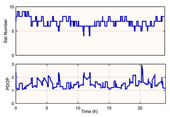
Figure 5.
Number of available satellites and PDOP value of METG–MET3 (3 km) baseline in DOY218 for BDS-3.
From Figure 4 and Table 5, we can see that in the instantaneous positioning mode, the ambiguity fixing rates of BDS-2+BDS-3 (B1I/B3I) and GPS (L1L2) were 100% and 99.60%, which are slightly higher than those of BDS-3 (B1I/B3I), BDS-3 (B1C/B2a), and BDS-3 (B1C/B2a/B3I). In terms of positioning accuracy, BDS-2+BDS-3 (B1I/B3I) has the highest number of satellites and the smallest PDOP value, and the triple-frequency BDS-3 (B1C/B2a/B3I) observation has more observation numbers due to the additional frequency, which leads to the highest positioning accuracy. In the continuous positioning mode, the positioning accuracy is significantly improved compared with the Instantaneous mode. In DOY218, due to the low number of BDS-3 satellites, the B1CB2a positioning error is large in the instantaneous mode, but it can still achieve high accuracy positioning when the continuous mode is selected.
Since single epoch RTK ambiguity fixing ignores the correlation of ambiguities among epochs, its ambiguity fixing rate is low, especially in the case of long baseline RTK positioning, and it is difficult to get a better RTK performance. Therefore, in practical applications, continuous ambiguity fixing strategy is generally adopted.
To analyze the effect of the increasing baseline length, three groups of baselines, TGCU–TGBU (30 km), TGCU-TGDA (96 km), and TGCU-TGD2 (128 km), were selected. The RMSs of the above five frequency sets (BDS-3 (B1C/B2a), BDS-2+BDS-3 (B1I/B3I), GPS (L1L2), BDS-3 (B1C/B2a/B3I), BDS-3 (B1I/B3I)) in the RTK positioning mode are shown in Figure 6, Figure 7 and Figure 8, and the seven-day RMS and ambiguity fixing rates of the average values are shown in Table 6, Table 7 and Table 8. In the region where the three baselines are located, the ionosphere is more active on two days between DOY220 and DOY221, resulting in generally high RMS values and slightly poor positioning accuracy. Due to the fewer visible satellites and poorer geometry distribution of BDS-3, the ambiguity fixing rates of BDS-3 (B1C/B2a), BDS-3 (B1C/B2a/B3I), and BDS-3 (B1I/B3I) are lower than those of BDS-2+BDS-3 (B1I/B3I) and GPS (L1L2). When the baseline length increases, the atmosphere residual increases and the accuracy of the ambiguity floating-point solution decreases, which makes the ambiguity fixing rate decrease. On the other hand, the increase in atmosphere residual increases the probability of ambiguity being fixed incorrectly, which affects the RTK positioning accuracy. The positioning accuracy of the five frequency sets is comparable for the short baseline, and the positioning accuracy of the BDS-2+BDS-3 (B1I/B3I) and GPS (L1L2) is slightly better.
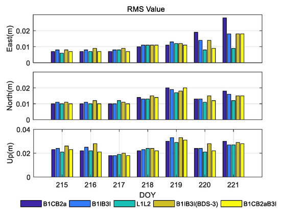
Figure 6.
TGCU–TGBU (30 km) medium baseline RTK positioning accuracy.
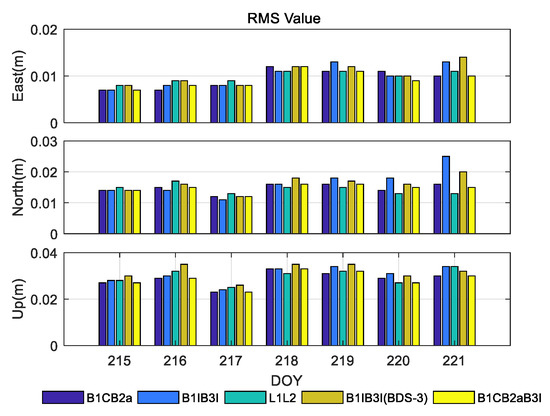
Figure 7.
TGDA-TGCU (96 km) medium baseline RTK positioning accuracy.
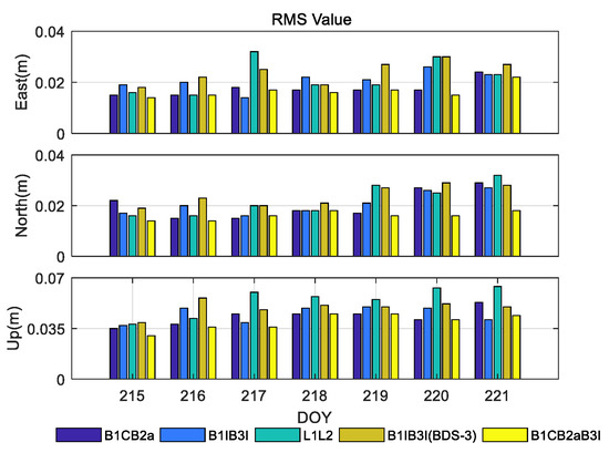
Figure 8.
TGD2-TGCU (128 km) long baseline RTK positioning accuracy.

Table 6.
TGCU–TGBU (30 km) average of medium baseline RTK RMS and ambiguity fixing rate.

Table 7.
TGDA-TGCU (96 km) average of medium baseline RTK RMS and ambiguity fixing rate.

Table 8.
TGD2-TGCU (128 km) average of long baseline RTK RMS and ambiguity fixing rate.
From Figure 6, Figure 7 and Figure 8, we can see that with the increase in baseline length, the advantages of BDS-3 (B1C/B2a) and BDS-3 (B1C/B2a/B3I) become obvious, with errors in the N, E, and U directions being within 0.015 m, 0.010 m, and 0.030 m or less. Under the condition that only the BDS-3 satellite is used, the triple-frequency BDS-3 (B1C/B2a/B3I) is superior to the BDS-3 (B1C/B2a) and BDS-3 (B1I/B3I) in both positioning accuracy and ambiguity fixing rate. However, the improvement relative to BDS-3 (B1C/B2a) is not significant.
4.3. Ratio-Test
The ratio-factor ratio is defined as the ratio of the weight sum of the squared residuals by the second-best solution to one by the best. Generally, the larger the ratio value, the higher the reliability of the ambiguity fixing solution. Therefore, the magnitude of the ratio value is also an important way to evaluate the positioning accuracy. Taking baselines TGCU–TGBU (30 km), TGCU-TGDA (96 km), and TGCU-TGD2 (128 km) on DOY218 as examples, the variation in ratio values for the five frequency sets is shown in Figure 9, Figure 10 and Figure 11. At the short baseline RTK positioning mode, the ratio values are larger. BDS-3 has fewer visible satellites and poorer geometry distribution, resulting in a smaller ratio value for BDS-3 (B1C/B2a), BDS-3 (B1I/B3I) and BDS-3 (B1C/B2a/B3I) than for BDS-2+BDS-3 (B1I/B3I) and GPS (L1L2). When the baseline length increases, the increase in the atmospheric residual error reduces the accuracy of the floating-point solution, and the ratio value decreases. For the period where the ratio values are too small, it may be that there are several satellites with low elevations during that period. It is also found that the fact that the ionosphere is most active around 2:00 p.m. at the local time leads to low ratio values for the five frequencies.
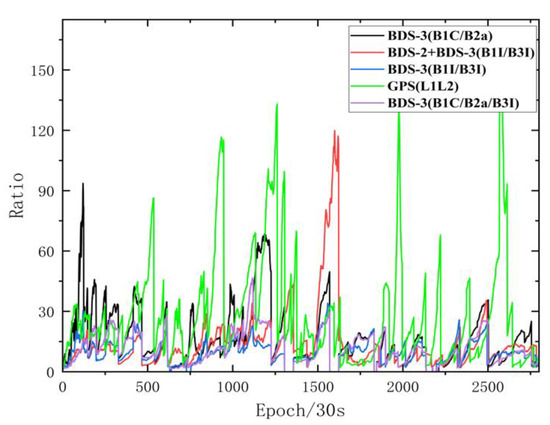
Figure 9.
Ratio value variation of TGCU–TGBU (30 km).
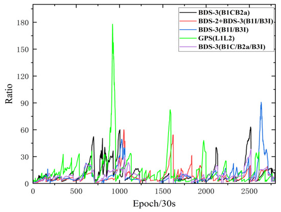
Figure 10.
Ratio value variation of TGCU-TGDA (96 km).
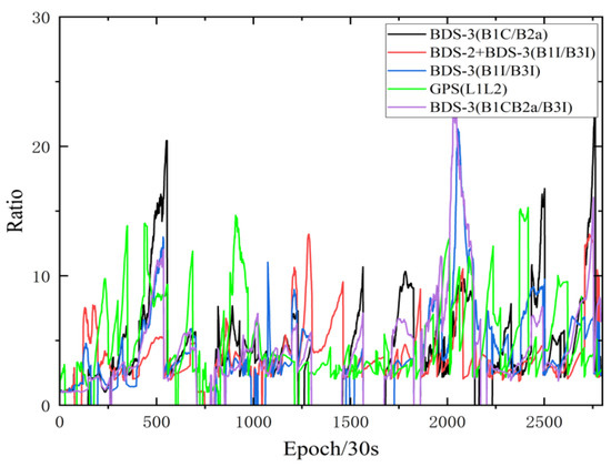
Figure 11.
Ratio value variation of TGCU-TGD2 (128 km).
4.4. Time to First Fix
Time to first fix is the time taken to initially fix the ambiguities, which is another indicator to evaluate the performance of RTK. Factors affecting the time to first fix of ambiguity include: the number of observation frequencies, PDOP, how fast the relative geometric configuration changes between the satellite and the receiver, observation accuracy, correlation between observations, data sampling rate, and the magnitude of atmospheric error delay [21,22]. To analyze the influence of the baseline length on TTFF, the data on 218 baselines of TGBU-TGCU (30 km) and TGCU-TGDA (96 km) were selected, and the daily observation data were divided into a total of 24 segments per 1-h period for testing. (When performing a positioning solution, each period is reinitialized.) In this research, the following three conditions are used as the index of ambiguity fixing:
- (1)
- Coordinate deviation in horizontal direction <0.1 m; coordinate deviation in vertical direction <0.2 m.
- (2)
- (3)
- The current epoch and the following nine consecutive epochs all satisfy (1), (2).
As shown in Figure 12, the zero fixing time on some frequencies means that it can be fixed on the first epoch. At the short-baseline RTK positioning mode, the TTFF is short, and the first epoch ambiguity can be fixed correctly in multiple time periods. When the baseline length increases, the TTFF increases due to the need to separate atmospheric errors. Since the ionosphere is more active due to the higher temperature at noon, the TTFF is longer during that time. BDS-3 has fewer visible satellites and poorer geometry distribution, resulting in longer TTFFs for BDS-3 (B1C/B2a), BDS-3 (B1I/B3I), and BDS-3 (B1C/B2a/B3I) than for BDS-2+BDS-3 (B1I/B3I) and GPS (L1L2). BDS-3 (B1C/B2a) and BDS-3 (B1C/B2a/B3I) were better than BDS-3 (B1I/B3I) in the case of a BDS-3 only system.
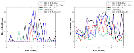
Figure 12.
Time to first fix of baseline TGCU–TGBU (left); time to first fix of baseline TGCU-TGDA (right).
5. Conclusions
In this paper, based on the five sets of baselines with seven-day observation data, four aspects of multi-GNSS multi-frequency RTK were evaluated successively in terms of the number of satellites and PDOP values, positioning accuracy, ratio values, and the time to first fix of ambiguity. We draw the following conclusions:
- The positioning accuracy of BDS-2+BDS-3 (B1I/B3I) dual-frequency RTK has reached a comparable performance to GPS (L1L2) in short baseline RTK and is slightly better than GPS (L1L2) in long baseline RTK.
- The BDS-3 (B1C/B2a/B3I) triple-frequency RTK has the highest positioning accuracy and is higher than BDS-3 (B1C/B2a) and BDS-3 (B1I/B3I) in terms of both positioning accuracy and ambiguity fixing rate. However, the improvement relative to BDS-3 (B1C/B2a) is not significant.
- The positioning accuracies of single-frequency bands B1C, BII, L1, and B3I were about the same, while the accuracy for band B2a was lower.
- As the baseline length increases, the positioning accuracy of the five frequencies decreases, the ratio value becomes smaller, and the TTFF becomes longer.
- The ambiguity fixing rates of GPS (L1L2) and BDS-2+BDS-3 (B1I/B3I) are comparable and are at the highest level among the five frequencies. GPS (L1L2) has the shortest time to first fix and BDS-2+BDS-3 (B1I/B3I) has the second shortest.
- BDS-3 (B1C/B2a) dual-frequency RTK has better than 2 cm positioning accuracy in the N and E directions and better than 3 cm positioning accuracy in the vertical direction within 100 km.
In this paper, the selection of stations was limited by the length of the baseline. All the stations selected are located in Europe, not involving the Asian region and the American region, which has certain regional limitations. For the analysis of positioning performance, we chose only BDS and GPS, and the baseline length only involves long baselines, and no in-depth study has been conducted for very long baselines (>500 km). Only static data are used; no real dynamic data are involved in the evaluation. Future research in this area should be oriented to a wider area and introduce more satellite navigation systems.
Author Contributions
E.W. researched the performance evaluation method. W.S. (Wei Song) validated the results and undertook the writing. Y.Z. researched the model and revised the written work. X.S. investigated the related work. Z.W. prepared the data. S.X. provided the funding. W.S. (Wansen Shu) helped validated the results. All authors have read and agreed to the published version of the manuscript.
Funding
This study was supported by the National Natural Science Foundation of China (62173237, 71731001), the Open Fund of Key Laboratory of Civil Aviation Flights Wide Area Surveillance and Safety Control technology for of Civil Aviation University of China (202105), the Applied Basic Research Programs of Liaoning Province (2022063), the Talent Project of Revitalization Liaoning (XLYC1907022), the Key R & D projects of Liaoning Province (2020JH2/10100045), the Natural Science Foundation of Liaoning Province (2019-MS-251), the Scientific Research Project of Liaoning Provincial Department of Education (JYT2020142), and the High-Level Innovation Talent Project of Shenyang (RC190030).
Data Availability Statement
All data can be available from Multi-GNSS Experiment (MGEX) or by contacting the primary author.
Conflicts of Interest
The authors declare no conflict of interest.
References
- Yuanxi, Y.; Li, L.; Jinlong, L.; Yufei, Y.; Tianqiao, Z.; Yue, M.; Bijiao, S.; Xia, R. Featured services and performance of BDS-3. Sci. Bull. 2021, 66, 2135–2143. [Google Scholar]
- Minghua, W.; Jiexian, W.; Danan, D.; Lingdong, M.; Junping, C.; Ahao, W.; Haomeng, C. Performance of BDS-3: Satellite visibility and dilution of precision. GPS Solut. 2019, 23, 1–14. [Google Scholar]
- Junbo, S.; Chenhao, O.; Huang, Y.; Wenjie, P. Assessment of BDS-3 global positioning service: Ephemeris, SPP, PPP, RTK, and new signal. GPS Solut. 2020, 24, 1–14. [Google Scholar]
- Zhang, Q.; Zhu, Y.; Chen, Z. An In-Depth Assessment of the New BDS-3 B1C and B2a Signals. Remote Sens. 2021, 13, 788. [Google Scholar] [CrossRef]
- Weikai, M.; Bofeng, L.; Zhiteng, Z.; Xuewen, Z. Combined BeiDou-2 and BeiDou-3 instantaneous RTK positioning: Stochastic modeling and positioning performance assessment. J. Spat. Sci. 2020, 65, 7–24. [Google Scholar]
- Yunbin, Y.; Xiaolong, M.; Baocheng, Z. Initial assessment of single and dual-frequency BDS-3 RTK positioning. Satell. Navig. 2020, 1, 1–7. [Google Scholar]
- Odijk, D. Weighting ionospheric corrections to improve fast GPS positioning over medium distances. In Proceeding of the 13th International Technical Meeting of the Satellite Division of the Institute of Navigation (ION GPS 2000), Salt Lake City, UT, USA, 19–22 September 2000; pp. 1113–1123. [Google Scholar]
- Takasu, T.; Yasuda, A. Kalman-Filter-Based Integer Ambiguity Resolution Strategy for Long-Baseline RTK with Ionosphere and Troposphere Estimation. In Proceedings of the 23rd International Technical Meeting of the Satellite Division of the Institute of Navigation, Portland, OR, USA, 21–24 September 2010. [Google Scholar]
- Bao, S.; Hui, L.; Xu, L. Performance Analysis of BDS Medium-Long Baseline RTK Positioning Using an Empirical Troposphere Model. Sensors 2018, 18, 1199. [Google Scholar] [CrossRef] [PubMed] [Green Version]
- Elliott, D.K.; Christopher, J.H. Understanding GPS Principles and Applications, 3rd ed.; Artech House: Norwood, MA, USA, 1996; pp. 308–318. [Google Scholar]
- Bofeng, L.; Yanming, F.; Weiguang, G.; Zhen, L. Real-time kinematic positioning over long baselines using triple-frequency BeiDou signals. IEEE Trans. Aerosp. Electron. Syst. 2015, 51, 3254–3269. [Google Scholar]
- Yuanxi, Y.; Weiguang, G. A new learning statistic for adaptive filter based on predicted residuals. Prog. Nat. Sci. 2006, 16, 833–837. [Google Scholar] [CrossRef]
- Ying, X.; Chen, W.; Lei, L.; Lizi, Y.; Min, L.; Shengli, W.X. GPS/BDS medium/long-range RTK constrained with tropospheric delay parameters from NWP model. Remote Sens. 2018, 10, 1113. [Google Scholar]
- Yize, Z.; Kubo, N.; Junping, C. Contribution of QZSS with four satellites to multi-GNSS long baseline RTK. J. Spat. Sci. 2020, 65, 41–60. [Google Scholar]
- Mowlam, A. Baseline precision results using triple frequency partial ambiguity sets. In Proceedings of the 17th International Technical Meeting of the Satellite Division of The Institute of Navigation (ION GNSS 2004), Long Beach, CA, USA, 24 September 2004; pp. 2509–2518. [Google Scholar]
- Verhagen, S.; Teunissen, P.J.G. The ratio test for future GNSS ambiguity resolution. GPS Solut. 2013, 17, 535–548. [Google Scholar] [CrossRef]
- Zhang, Y.; Chen, J.; Gong, X.; Chen, Q. The update of BDS-2 TGD and its impact on positioning. Adv. Space Res. 2020, 65, 2645–2661. [Google Scholar] [CrossRef]
- Takasu, T. RTKLIB ver.2.4.2 Manaul. Available online: https://www.rtklib.com/prog/manual_2.4.2.pdf (accessed on 23 July 2022).
- Lemmon, T.R.; Gerdan, G.P. The Influence of the Number of Satellites on the Accuracy of RTK GPS Positions. Aust. Surv. 1999, 44, 67–70. [Google Scholar] [CrossRef]
- Shengli, W.; Yulong, G.; Xiaolin, M. Modelling and Assessment of Single-Frequency PPP Time Transfer with BDS-3 B1I and B1C Observations. Remote Sens. 2022, 14, 1146. [Google Scholar]
- Teunissen, P.J.G.; Odijk, D.; Odolinski, R. A Method of Analysing a Signal Transmitted between A Global Satellite Navigation Satellite System and a Receiver. WO PCT/AU2016/050951, 10 October 2016. [Google Scholar]
- Shaoshi, W.; Xiubin, Z.; Liang, Z.; Chunlei, P. Improving reliability and efficiency of RTK ambiguity resolution with reference antenna array: BDS+GPS analysis and test. J. Geod. 2019, 98, 1297–1311. [Google Scholar]
Publisher’s Note: MDPI stays neutral with regard to jurisdictional claims in published maps and institutional affiliations. |
© 2022 by the authors. Licensee MDPI, Basel, Switzerland. This article is an open access article distributed under the terms and conditions of the Creative Commons Attribution (CC BY) license (https://creativecommons.org/licenses/by/4.0/).