
Locating Smartphone Indoors by Using Tightly Coupling Bluetooth Ranging and Accelerometer Measurements


Abstract
:1. Introduction
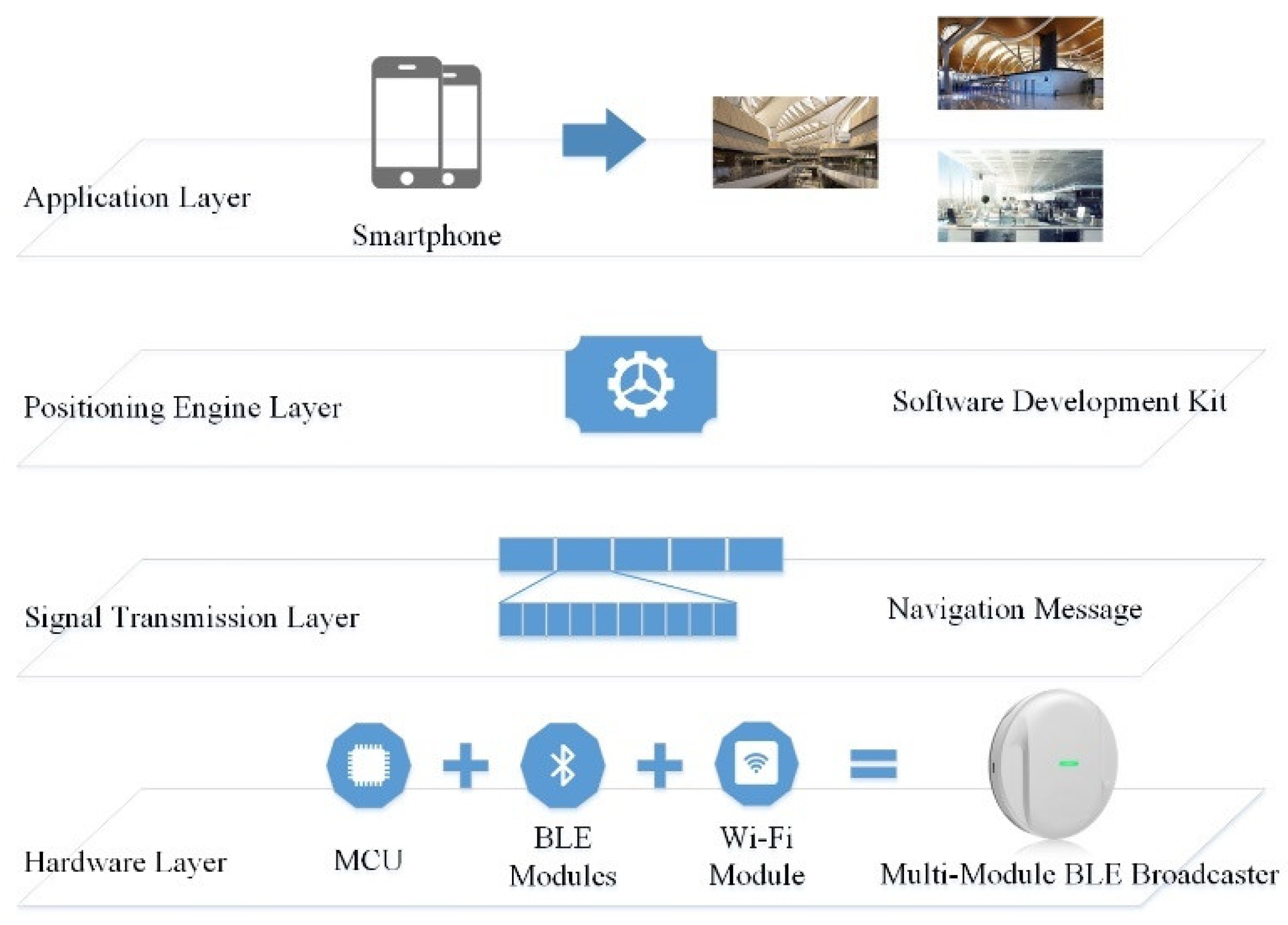
2. System Overview
- (1)
- Regarding the hardware layer, the MMBB consists of a micro-control unit, Bluetooth Low Energy modules, and a Wi-Fi module. The MMBB is suitable for low-power operation, which is below 100 mA in active mode and below 5 mA in stand-by mode, while providing a power supply of 2.5–5V; the transition time from stand-by mode to active mode is neglectable.
- (2)
- Regarding the signal transport layer, navigation message (NM) is designed based on the Bluetooth transmission protocol. Similar to the GNSS navigation message, encrypted MMBB state and navigation information are broadcasted to users. NM provides all the necessary information to enable the user to complete the positioning task, including MMBB parameters, service parameters, and positions in the WGS84 coordinate system, which are surveyed by the total station and real-time kinematic (RTK) GPS receiver. The broadcast frequency of the NM is up to 10 Hz to support a very fast time to first fix of 0.1 s. There is no limit to the number of users theoretically, as our system is operated in a broadcast mode.
- (3)
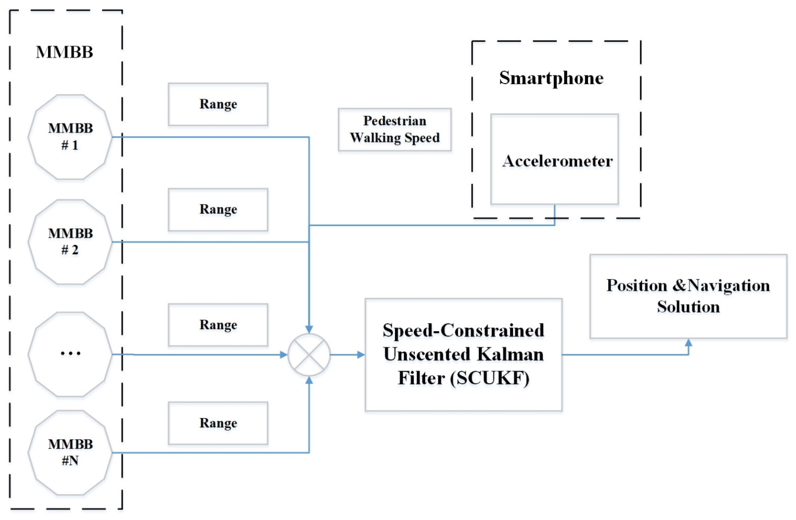
- For the positioning engine layer, the core of the positioning engine is the unscented Kalman filter method that tightly couples the BLE ranging measurements and the user walking speed for estimating the user position at an output frequency of 10 Hz. As the coordinates of the MMBBs determined during the installation phase are in a global coordinate system such as GPS, the output positions of the positioning engine are also in the same global coordinate system. Specifically, for the positioning phase, we first convert the latitude, longitude, and elevation into a local ENU coordinate system to ensure no loss of accuracy and the facilitation of calculations. After the positioning is completed, the ENU coordinates are converted to latitude and longitude for output to ensure consistency with the GPS output format. Therefore, the proposed system has a significant advantage in facilitating a seamless indoor/outdoor positioning solution. The algorithms implemented in the positioning engine take advantage of these characteristics and fully support seamlessly postponing indoor/outdoor positioning. The positioning engine is finally presented as a locator server running inside the smartphone to support application development. It is like a GPS locator running in the smartphone.
- (4)
- The application layer is based on the positioning engine, and mobile applications can then be developed. In the space where MMBB is installed, the positioning engine works independently without the need for knowledge of the positioning environment, such as building layout, fingerprint database, and so on. From the user perspective, it is very much like using GPS in an outdoor environment. The users only needs to turn on the mobile phone, and the positioning engine will output the positions automatically to be used by multiple applications.
3. Methodology
3.1. Finite Range Estimation Based on MMBB and Segmented Linear Model
| Algorithm 1. MMBB-Based Range Estimation Algorithm |
| Input: |
| Output: |
| 1. Calculate the ranges via the SLPLMs |
| 2. Select the ranges within three standard deviations. |
| 3. Sort the set of ranges in descending order. |
| 4. Remove toppercent and bottompercent of the range set. The parametersandare chosen from the range 5–15%. |
| 5. Average of the remaining rangesis the estimated range of the MMBB. |
| Return |
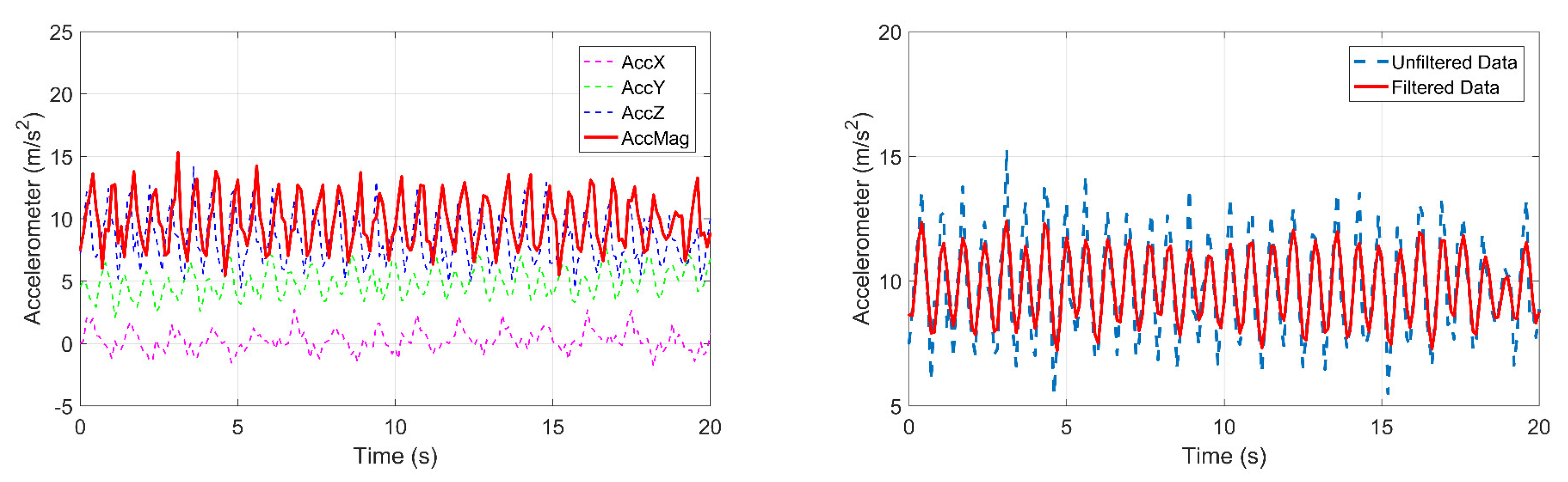
3.2. Pedestrian Walking Speed Measured by Accelerometer
3.3. Tightly Coupled Integration of MMBB Range and Accelerometer Integration System
3.3.1. Dynamic Model
3.3.2. Observation Model
3.3.3. Pedestrian Walking Speed Constrained Unscented Kalman Filter
| Algorithm 2. Pedestrian Walking Speed Constrained Unscented Kalman Filter Algorithm |
| Input: |
| Output: |
| Set. For i = 1 to N Generate sigma points: Generate the sigma points according to Equations (16)–(18). Time update: 1: Evaluate the sigma points with the dynamic model function according to Equation (19). 2: Evaluate the predicted state mean and error covariance according to Equations (20) and (21). 3: Evaluate the generate d sigma points with measurement function according to Equation (22). 4: Estimate the predicted measurement according to Equation (23). Measurement update 1: Estimate the innovation covariance matrix according to Equation (24). 2: Estimate the cross-covariance matrix according to Equation (25). 3: Calculate the Kalman gain according to Equation (26). 4: Estimate the updated state according to Equation (27). 5: Estimate the updated error covariance according to Equation (28). End |
4. Experimental Assessment
4.1. Setup
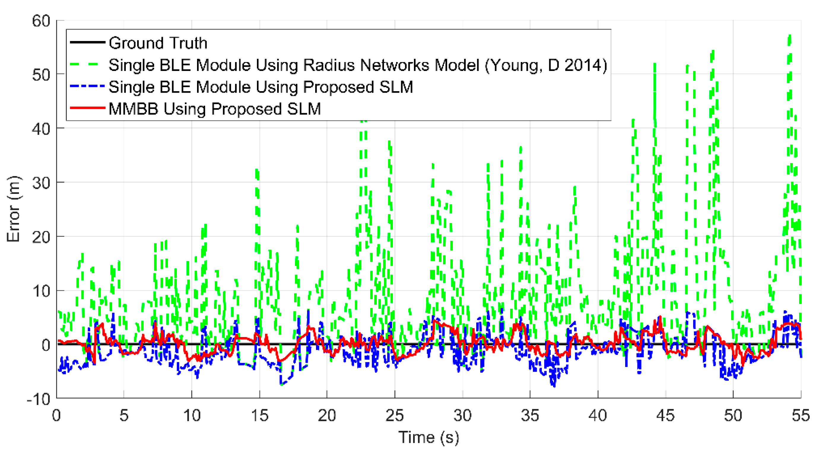
4.2. Experimental Results and Analysis
5. Conclusions
Author Contributions
Funding
Institutional Review Board Statement
Informed Consent Statement
Data Availability Statement
Conflicts of Interest
References
- Chen, R.; Chen, L. Indoor positioning with Smartphones: The state-of-the-art and the challenges. Acta Geod. Cartogr. Sin. 2017, 46, 1316–1326. [Google Scholar]
- Chen, R.; Guinness, R. Geospatial Computing in Mobile Devices; Artech House: Fitchburg, MA, USA, 2014. [Google Scholar]
- Passafiume, M.; Maddio, S.; Cidronali, A. An Improved Approach for RSSI-Based only Calibration-Free Real-Time Indoor Localization on IEEE 802.11 and 802.15. 4 Wireless Networks. Sensors 2017, 17, 717. [Google Scholar] [CrossRef] [PubMed] [Green Version]
- Dong, Q.; Dargie, W. Evaluation of the reliability of RSSI for indoor localization. In Proceedings of the Wireless Communications in Unusual and Confined Areas (ICWCUCA), Clermont Ferrand, France, 28–30 August 2012; pp. 1–6. [Google Scholar]
- Committee, I. Wireless LAN medium access control (MAC) and physical layer (PHY) specifications. IEEE Std. 1997, 802, 50. [Google Scholar]
- Liu, H.; Darabi, H.; Banerjee, P.; Liu, J. Survey of wireless indoor positioning techniques and systems. IEEE Trans. Syst. Man Cybern. Part C 2007, 37, 1067–1080. [Google Scholar] [CrossRef]
- Peng, X.; Chen, R.; Yu, K.; Guo, G.; Ye, F.; Xue, W. A new Wi-Fi dynamic selection of nearest neighbor localization algorithm based on RSS characteristic value extraction by hybrid filtering. Meas. Sci. Technol. 2020, 32, 034003. [Google Scholar] [CrossRef]
- Bi, J.; Huang, L.; Cao, H.; Yao, G.; Sang, W.; Zhen, J.; Liu, Y. Improved Indoor Fingerprinting Localization Method Using Clustering Algorithm and Dynamic Compensation. ISPRS Int. J. Geo-Inf. 2021, 10, 613. [Google Scholar] [CrossRef]
- Liu, J.; Chen, R.; Pei, L.; Guinness, R.; Kuusniemi, H. A hybrid smartphone indoor positioning solution for mobile LBS. Sensors 2012, 12, 17208–17233. [Google Scholar] [CrossRef] [PubMed]
- Kim, B.; Kwak, M.; Lee, J.; Kwon, T.T. A multi-pronged approach for indoor positioning with WiFi, magnetic and cellular signals. In Proceedings of the Indoor Positioning and Indoor Navigation (IPIN), Busan, Korea, 27–30 October 2014; pp. 723–726. [Google Scholar]
- Karlsson, F.; Karlsson, M.; Bernhardsson, B.; Tufvesson, F.; Persson, M. Sensor fused indoor positioning using dual band WiFi signal measurements. In Proceedings of the Control Conference (ECC), Linz, Austria, 15–17 July 2015; pp. 1669–1672. [Google Scholar]
- Jeon, J.-S.; Kong, Y.; Nam, Y.; Yim, K. An Indoor Positioning System Using Bluetooth RSSI with an Accelerometer and a Barometer on a Smartphone. In Proceedings of the Broadband and Wireless Computing, Communication and Applications (BWCCA), Krakow, Poland, 4–6 November 2015; pp. 528–531. [Google Scholar]
- Li, X.; Wang, J.; Liu, C.; Zhang, L.; Li, Z. Integrated WiFi/PDR/Smartphone using an adaptive system noise extended Kalman filter algorithm for indoor localization. ISPRS Int. J. Geo-Inf. 2016, 5, 8. [Google Scholar] [CrossRef] [Green Version]
- Li, Y.; Zhuang, Y.; Lan, H.; Zhou, Q.; Niu, X.; El-Sheimy, N. A hybrid WiFi/magnetic matching/PDR approach for indoor navigation with smartphone sensors. IEEE Commun. Lett. 2016, 20, 169–172. [Google Scholar] [CrossRef]
- Chen, R.; Chu, T.; Liu, K.; Liu, J.; Chen, Y. Inferring Human Activity in Mobile Devices by Computing Multiple Contexts. Sensors 2015, 15, 21219–21238. [Google Scholar] [CrossRef] [Green Version]
- Zhang, R.; Bannoura, A.; Höflinger, F.; Reindl, L.M.; Schindelhauer, C. Indoor localization using a smart phone. In Proceedings of the Sensors Applications Symposium (SAS), Galveston, TX, USA, 19–21 February 2013; pp. 38–42. [Google Scholar]
- Arshal, G. Error equations of inertial navigation. J. Guid. Control. Dyn. 1987, 10, 351–358. [Google Scholar] [CrossRef]
- Cho, S.Y.; Kim, B.D. Adaptive IIR/FIR fusion filter and its application to the INS/GPS integrated system. Automatica 2008, 44, 2040–2047. [Google Scholar] [CrossRef]
- Julier, S.; Uhlmann, J.; Durrant-Whyte, H.F. A new method for the nonlinear transformation of means and covariances in filters and estimators. IEEE Trans. Autom. Control. 2000, 45, 477–482. [Google Scholar] [CrossRef] [Green Version]
- Julier, S.J.; Uhlmann, J.K. Unscented filtering and nonlinear estimation. Proc. IEEE 2004, 92, 401–422. [Google Scholar] [CrossRef] [Green Version]
- Li, L.; Xia, Y. Stochastic stability of the unscented Kalman filter with intermittent observations. Automatica 2012, 48, 978–981. [Google Scholar] [CrossRef]
- Tang, X.; Yan, J.; Zhong, D. Square-root sigma-point Kalman filtering for spacecraft relative navigation. Acta Astronaut. 2010, 66, 704–713. [Google Scholar] [CrossRef]
- Wan, E.A.; Van Der Merwe, R. The unscented Kalman filter for nonlinear estimation. In Proceedings of the Adaptive Systems for Signal Processing, Communications, and Control Symposium, Lake Louise, AB, Canada, 4 October 2000; pp. 153–158. [Google Scholar]
- Ma, L.; Cao, N.; Feng, X.; Mao, M. Indoor Positioning Algorithm Based on Maximum Correntropy Unscented Information Filter. ISPRS Int. J. Geo-Inf. 2021, 10, 441. [Google Scholar] [CrossRef]
- Goldsmith, A. Wireless Communications; Cambridge University Press: Cambridge, UK, 2005. [Google Scholar]
- Chintalapudi, K.; Padmanabha Iyer, A.; Padmanabhan, V.N. Indoor localization without the pain. In Proceedings of the Sixteenth Annual International Conference on Mobile Computing and Networking, Chicago, IL, USA, 20–24 September 2010; pp. 173–184. [Google Scholar]
- Guo, G.; Chen, R.; Ye, F.; Liu, Z.; Xu, S.; Huang, L.; Li, Z.; Qian, L. A Robust Integration Platform of Wi-Fi RTT, RSS Signal and MEMS-IMU for Locating Commercial Smartphone Indoors. IEEE Internet Things J. 2022, 107, 2411–2502, early access. [Google Scholar] [CrossRef]
- Mazuelas, S.; Bahillo, A.; Lorenzo, R.M.; Fernandez, P.; Lago, F.A.; Garcia, E.; Blas, J.; Abril, E.J. Robust Indoor Positioning Provided by Real-Time RSSI Values in Unmodified WLAN Networks. IEEE J. Sel. Top. Signal Process. 2009, 3, 821–831. [Google Scholar] [CrossRef]
- Proakis, J.G. Digital Communications; Van Nostrand: New York, NY, USA, 1983. [Google Scholar]
- Bylemans, I.; Weyn, M.; Klepal, M. Mobile phone-based displacement estimation for opportunistic localisation systems. In Proceedings of the Mobile Ubiquitous Computing, Systems, Services and Technologies, Sliema, Malta, 11–16 October 2009; pp. 113–118. [Google Scholar]
- Brajdic, A.; Harle, R. Walk detection and step counting on unconstrained smartphones. In Proceedings of the 2013 ACM International Joint Conference on Pervasive and Ubiquitous Computing, Zurich, Switzerland, 8–12 September 2013; pp. 225–234. [Google Scholar]
- Renaudin, V.; Susi, M.; Lachapelle, G. Step length estimation using handheld inertial sensors. Sensors 2012, 12, 8507–8525. [Google Scholar] [CrossRef]
- Guo, G.; Chen, R.; Ye, F.; Chen, L.; Pan, Y.; Liu, M.; Cao, Z. A Pose Awareness Solution for Estimating Pedestrian Walking Speed. Remote Sens. 2019, 11, 55. [Google Scholar] [CrossRef] [Green Version]
- Pratama, A.R.; Widyawan; Hidayat, R. Smartphone-based Pedestrian Dead Reckoning as an indoor positioning system. In Proceedings of the International Conference on System Engineering and Technology, Bandung, Indonesia, 11–12 September 2012; pp. 1–6. [Google Scholar]
- Weinberg, H. Using the ADXL202 in pedometer and personal navigation applications. Analog. Devices AN-602 Appl. Note 2002, 2, 1–6. [Google Scholar]
- Tian, Q.; Salcic, Z.; Kevin, I.; Wang, K.; Pan, Y. A multi-mode dead reckoning system for pedestrian tracking using smartphones. IEEE Sens. J. 2016, 16, 2079–2093. [Google Scholar] [CrossRef]
- Kim, J.W.; Jang, H.J.; Hwang, D.-H.; Park, C. A step, stride and heading determination for the pedestrian navigation system. Positioning 2004, 3, 273–279. [Google Scholar] [CrossRef] [Green Version]
- Chen, R.; Pei, L.; Chen, Y. A smart phone based PDR solution for indoor navigation. In Proceedings of the Proceedings of the 24th International Technical Meeting of the Satellite Division of the Institute of Navigation, Portland, OR, USA, 20–23 September 2011; pp. 1404–1408. [Google Scholar]
- Young, D. 2014. Fundamentals of Beacon Ranging. Available online: http://developer.radiusnetworks.com/2014/12/04/fundamentals-of-beacon-ranging.html (accessed on 1 April 2022).


| Stat. | Radius Networks (Young, D 2014) [39] | Proposed |
|---|---|---|
| Mean (m) | 3.21 | 0.94 |
| Std (m) | 4.59 | 1.35 |
| Var (m2) | 21.12 | 1.82 |
| 95th (m) | 12.00 | 5.01 |
| Median (m) | 1.55 | 0.50 |
| Stat. | Single BLE Module Using (Young, D 2014) [39] | Single BLE Module Using SLM | Proposed |
|---|---|---|---|
| Mean (m) | 9.72 | 2.79 | 1.43 |
| Std (m) | 11.15 | 1.74 | 1.03 |
| Var (m2) | 124.34 | 3.04 | 1.07 |
| Max (m) | 57.87 | 7.80 | 5.12 |
| 95th (m) | 33.87 | 5.76 | 3.53 |
| Median (m) | 5.91 | 2.73 | 1.22 |
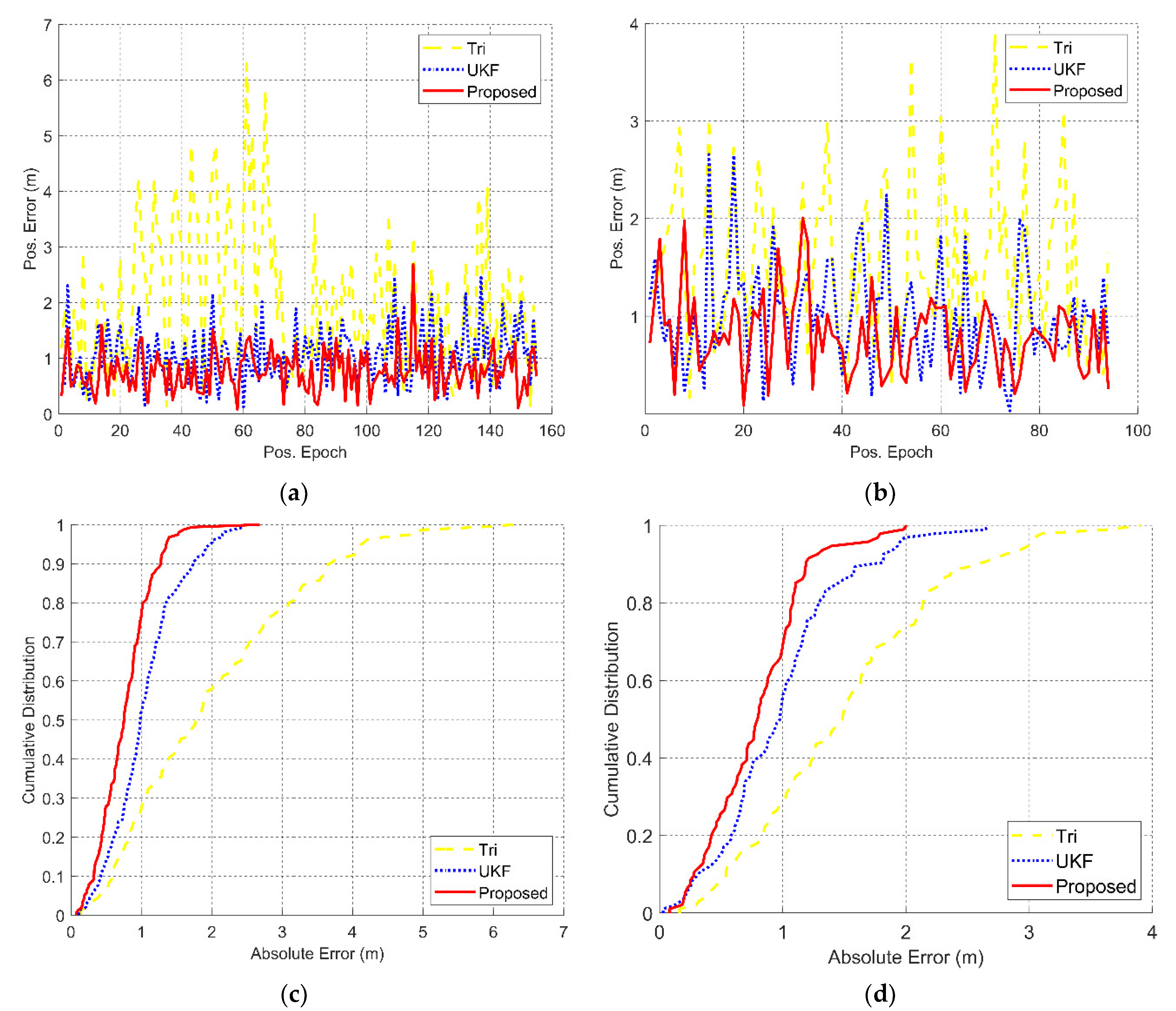
| Test | Stat. | Triangulation | UKF | Proposed |
|---|---|---|---|---|
| 1 | Mean (m) | 1.99 | 1.02 | 0.77 |
| Std (m) | 1.25 | 0.63 | 0.37 | |
| Var (m2) | 1.58 | 0.41 | 0.14 | |
| Max (m) | 6.28 | 4.29 | 2.68 | |
| 95th (m) | 1.93 | 0.96 | 0.81 | |
| Median (m) | 1.78 | 0.89 | 0.75 | |
| Min (m) | 0.13 | 0.12 | 0.07 | |
| 2 | Mean (m) | 1.52 | 0.95 | 0.80 |
| Std (m) | 0.78 | 0.52 | 0.39 | |
| Var (m2) | 0.62 | 0.27 | 0.15 | |
| Max (m) | 3.91 | 2.77 | 2.01 | |
| 95th (m) | 2.99 | 2.16 | 1.39 | |
| Median (m) | 1.48 | 0.88 | 0.79 | |
| Min (m) | 0.16 | 0.06 | 0.08 |
Publisher’s Note: MDPI stays neutral with regard to jurisdictional claims in published maps and institutional affiliations. |
© 2022 by the authors. Licensee MDPI, Basel, Switzerland. This article is an open access article distributed under the terms and conditions of the Creative Commons Attribution (CC BY) license (https://creativecommons.org/licenses/by/4.0/).
Share and Cite
Yan, K.; Chen, R.; Guo, G.; Chen, L. Locating Smartphone Indoors by Using Tightly Coupling Bluetooth Ranging and Accelerometer Measurements. Remote Sens. 2022, 14, 3468. https://doi.org/10.3390/rs14143468
Yan K, Chen R, Guo G, Chen L. Locating Smartphone Indoors by Using Tightly Coupling Bluetooth Ranging and Accelerometer Measurements. Remote Sensing. 2022; 14(14):3468. https://doi.org/10.3390/rs14143468
Chicago/Turabian StyleYan, Ke, Ruizhi Chen, Guangyi Guo, and Liang Chen. 2022. "Locating Smartphone Indoors by Using Tightly Coupling Bluetooth Ranging and Accelerometer Measurements" Remote Sensing 14, no. 14: 3468. https://doi.org/10.3390/rs14143468
APA StyleYan, K., Chen, R., Guo, G., & Chen, L. (2022). Locating Smartphone Indoors by Using Tightly Coupling Bluetooth Ranging and Accelerometer Measurements. Remote Sensing, 14(14), 3468. https://doi.org/10.3390/rs14143468